EP3795024A1 - Measurement plate and foot outline creation system - Google Patents
Measurement plate and foot outline creation system Download PDFInfo
- Publication number
- EP3795024A1 EP3795024A1 EP19894394.6A EP19894394A EP3795024A1 EP 3795024 A1 EP3795024 A1 EP 3795024A1 EP 19894394 A EP19894394 A EP 19894394A EP 3795024 A1 EP3795024 A1 EP 3795024A1
- Authority
- EP
- European Patent Office
- Prior art keywords
- foot
- measuring board
- placement
- measurement
- wall part
- Prior art date
- Legal status (The legal status is an assumption and is not a legal conclusion. Google has not performed a legal analysis and makes no representation as to the accuracy of the status listed.)
- Pending
Links
Images




Classifications
-
- A—HUMAN NECESSITIES
- A43—FOOTWEAR
- A43D—MACHINES, TOOLS, EQUIPMENT OR METHODS FOR MANUFACTURING OR REPAIRING FOOTWEAR
- A43D1/00—Foot or last measuring devices; Measuring devices for shoe parts
- A43D1/02—Foot-measuring devices
- A43D1/025—Foot-measuring devices comprising optical means, e.g. mirrors, photo-electric cells, for measuring or inspecting feet
-
- A—HUMAN NECESSITIES
- A43—FOOTWEAR
- A43D—MACHINES, TOOLS, EQUIPMENT OR METHODS FOR MANUFACTURING OR REPAIRING FOOTWEAR
- A43D1/00—Foot or last measuring devices; Measuring devices for shoe parts
- A43D1/06—Measuring devices for the inside measure of shoes, for the height of heels, or for the arrangement of heels
-
- A—HUMAN NECESSITIES
- A61—MEDICAL OR VETERINARY SCIENCE; HYGIENE
- A61B—DIAGNOSIS; SURGERY; IDENTIFICATION
- A61B5/00—Measuring for diagnostic purposes; Identification of persons
- A61B5/103—Measuring devices for testing the shape, pattern, colour, size or movement of the body or parts thereof, for diagnostic purposes
- A61B5/107—Measuring physical dimensions, e.g. size of the entire body or parts thereof
- A61B5/1074—Foot measuring devices
-
- G—PHYSICS
- G01—MEASURING; TESTING
- G01B—MEASURING LENGTH, THICKNESS OR SIMILAR LINEAR DIMENSIONS; MEASURING ANGLES; MEASURING AREAS; MEASURING IRREGULARITIES OF SURFACES OR CONTOURS
- G01B11/00—Measuring arrangements characterised by the use of optical techniques
- G01B11/02—Measuring arrangements characterised by the use of optical techniques for measuring length, width or thickness
- G01B11/022—Measuring arrangements characterised by the use of optical techniques for measuring length, width or thickness by means of tv-camera scanning
-
- G—PHYSICS
- G01—MEASURING; TESTING
- G01B—MEASURING LENGTH, THICKNESS OR SIMILAR LINEAR DIMENSIONS; MEASURING ANGLES; MEASURING AREAS; MEASURING IRREGULARITIES OF SURFACES OR CONTOURS
- G01B11/00—Measuring arrangements characterised by the use of optical techniques
- G01B11/24—Measuring arrangements characterised by the use of optical techniques for measuring contours or curvatures
-
- G—PHYSICS
- G01—MEASURING; TESTING
- G01B—MEASURING LENGTH, THICKNESS OR SIMILAR LINEAR DIMENSIONS; MEASURING ANGLES; MEASURING AREAS; MEASURING IRREGULARITIES OF SURFACES OR CONTOURS
- G01B21/00—Measuring arrangements or details thereof, where the measuring technique is not covered by the other groups of this subclass, unspecified or not relevant
- G01B21/02—Measuring arrangements or details thereof, where the measuring technique is not covered by the other groups of this subclass, unspecified or not relevant for measuring length, width, or thickness
- G01B21/04—Measuring arrangements or details thereof, where the measuring technique is not covered by the other groups of this subclass, unspecified or not relevant for measuring length, width, or thickness by measuring coordinates of points
- G01B21/042—Calibration or calibration artifacts
-
- G—PHYSICS
- G01—MEASURING; TESTING
- G01B—MEASURING LENGTH, THICKNESS OR SIMILAR LINEAR DIMENSIONS; MEASURING ANGLES; MEASURING AREAS; MEASURING IRREGULARITIES OF SURFACES OR CONTOURS
- G01B3/00—Measuring instruments characterised by the use of mechanical techniques
- G01B3/002—Details
- G01B3/004—Scales; Graduations
-
- G—PHYSICS
- G01—MEASURING; TESTING
- G01B—MEASURING LENGTH, THICKNESS OR SIMILAR LINEAR DIMENSIONS; MEASURING ANGLES; MEASURING AREAS; MEASURING IRREGULARITIES OF SURFACES OR CONTOURS
- G01B3/00—Measuring instruments characterised by the use of mechanical techniques
- G01B3/02—Rulers with scales or marks for direct reading
- G01B3/04—Rulers with scales or marks for direct reading rigid
- G01B3/06—Rulers with scales or marks for direct reading rigid folding
-
- G—PHYSICS
- G01—MEASURING; TESTING
- G01B—MEASURING LENGTH, THICKNESS OR SIMILAR LINEAR DIMENSIONS; MEASURING ANGLES; MEASURING AREAS; MEASURING IRREGULARITIES OF SURFACES OR CONTOURS
- G01B5/00—Measuring arrangements characterised by the use of mechanical techniques
- G01B5/0002—Arrangements for supporting, fixing or guiding the measuring instrument or the object to be measured
- G01B5/0004—Supports
-
- G—PHYSICS
- G06—COMPUTING OR CALCULATING; COUNTING
- G06T—IMAGE DATA PROCESSING OR GENERATION, IN GENERAL
- G06T7/00—Image analysis
- G06T7/60—Analysis of geometric attributes
-
- G—PHYSICS
- G06—COMPUTING OR CALCULATING; COUNTING
- G06T—IMAGE DATA PROCESSING OR GENERATION, IN GENERAL
- G06T2207/00—Indexing scheme for image analysis or image enhancement
- G06T2207/30—Subject of image; Context of image processing
- G06T2207/30204—Marker
Definitions
- Patent Literature 1 Japanese Unexamined Patent Application Publication No. 2001-327304
- the side surface portion 44, the upper surface portion 50, the side surface portion 46, the lower surface portion 52, and the side surface portion 48 are arranged in this order, with the longer sides thereof are in contact with each other, such as to form a large rectangular shape.
- the end surface portion 54 of a substantially rectangular shape is formed.
- the lid 32 of a substantially rectangular shape is formed.
- a reinforcement portion 56 is formed to reinforce the end surface portions 54 when the shoebox is formed.
- Each end surface portion 54 is also a portion that forms a wall part 4, and has two tongues 10 formed in the end part thereof. Also, two slits 12 are formed near each of the boundary between one end surface portion 54 and the upper surface portion 50 and the boundary between the other end surface portion 54 and the lower surface portion 52.
- Each tongue 10 has a size such as to be fitted into a slit 12, and, by folding each end surface portion 54 at the center in a Y-axis direction around the X-axis, the tongues 10 can be fitted into the corresponding slits 12.
- the wall parts 4 are formed.
- any terminal provided with a communication function and an image capturing function such as a camera-equipped cellular phone, may be used.
- a measurer places the feet on the placement part of the measuring board, captures an image of the feet by means of an image capturing unit 108, and transmits the image to the foot shape creating unit 106.
- the foot shape creating unit 106 is constituted by an external server or the like.
- the foot shape creating unit 106 includes a data storage unit 110 that stores image data transmitted from the measurer or other users in the past, and foot shape data obtained by analyzing the image data, for example.
- the data storage unit 110 may also store foot shape data held by manufacturers. By referring to a data set stored in the data storage unit 110, the foot shape creating unit 106 generates foot shape data.
- the measuring board can be distributed during sale of shoes.
- foot shape data can be generated using a measuring board having a simple structure.
Landscapes
- Physics & Mathematics (AREA)
- General Physics & Mathematics (AREA)
- Life Sciences & Earth Sciences (AREA)
- Health & Medical Sciences (AREA)
- Biophysics (AREA)
- Engineering & Computer Science (AREA)
- Medical Informatics (AREA)
- Animal Behavior & Ethology (AREA)
- Biomedical Technology (AREA)
- Heart & Thoracic Surgery (AREA)
- Oral & Maxillofacial Surgery (AREA)
- Molecular Biology (AREA)
- Surgery (AREA)
- Pathology (AREA)
- General Health & Medical Sciences (AREA)
- Public Health (AREA)
- Veterinary Medicine (AREA)
- Dentistry (AREA)
- Geometry (AREA)
- Computer Vision & Pattern Recognition (AREA)
- Theoretical Computer Science (AREA)
- Footwear And Its Accessory, Manufacturing Method And Apparatuses (AREA)
Abstract
Description
- The present invention relates to a measuring board and a foot shape creating system.
- Measuring boards for measuring foot shapes have been conventionally known and are used when customers purchase shoes in stores, for example. A measuring board is used to measure a longitudinal length of a foot, a foot width, an instep size, or the like (
Patent Literature 1, for example). - [Patent Literature 1] Japanese Unexamined Patent Application Publication No.
2001-327304 - With widespread use of the Internet in recent years, when people purchase shoes, the chances to purchase shoes on the Internet, without actually visiting stores, are increasing. Since shoe sizes vary depending on each shoe type or each shoe manufacturer, when shoes are purchased on the Internet, the sizes may sometimes not fit. Therefore, there is a need for enabling purchasers to measure their foot sizes by themselves at home, for example.
- The present invention has been made to solve the problem above, and a purpose thereof is to provide a measuring board having a simple structure.
- The present invention includes a main body having a foldable structure, and the main body includes a placement part on which a foot is placed and that includes a measurement marker, a wall part provided adjacent to the placement part and configured to position a heel during measurement, and a supporting structure that supports the wall part.
- The present invention provides a measuring board having a simple structure.
- Embodiments will now be described, by way of example only, with reference to the accompanying drawings which are meant to be exemplary, not limiting, and wherein like elements are numbered alike in several Figures, in which:
-
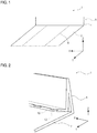
FIG. 1 is a perspective view of a measuring board; -
FIG. 2 is a magnified perspective view of the measuring board; -
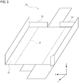
FIG. 3 is a perspective view of a measuring board according to a modification; -
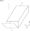
FIG. 4 is a perspective view of a shoebox; -
FIG. 5 is an exploded plan view of a measuring board; -
FIG. 6 is a diagram that shows a process step for assembling the measuring board; -
FIG. 7 is a diagram that shows another process step for assembling the measuring board; -
FIG. 8 is a diagram that shows yet another process step for assembling the measuring board; -
FIG. 9 is a diagram that shows still yet another process step for assembling the measuring board; -
FIG. 10 is an exploded perspective view of a shoebox according to a modification; -
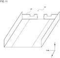
FIG. 11 is a perspective view of a measuring board assembled after the shoebox is opened and flattened; -
FIG. 12 is a block diagram of a foot shape creating system; -
FIG. 13 is a plan view that shows an example of the placement part; and -
FIG. 14 is a plan view that shows another example of the placement part. - In the following, an embodiment of the present invention will be described. In the embodiment below, the terms "width direction", "height direction", and "longitudinal direction" may be used to describe directions. A width direction means a width direction of a foot placed on a measuring board. A longitudinal direction means a longitudinal direction of a foot placed on a measuring board. A height direction means a height direction viewed from a measurer placing a foot on a measuring board. Also, using a three-dimensional Cartesian coordinate system, a width direction of a measuring board may be referred to as an X-axis direction, a longitudinal direction thereof may be referred to as a Y-axis direction, and a height direction thereof may be referred to as a Z-axis direction, for the sake of convenience.
-
FIG. 1 is a perspective view of a measuring board. In the illustrated example, ameasuring board 1 includes amain body 6, which includes aplacement part 2 on which a foot is placed, and awall part 4 used to position the foot. Themain body 6 may be suitably formed by folding a sheet of board into a predetermined shape. - The
main body 6 may be suitably made of paper that is sufficiently thick and foldable, such as corrugated cardboard. Parts of themain body 6, including theplacement part 2 and thewall part 4, are formed by assembling a sheet of paper cut out into a predetermined shape. - The
placement part 2 is an area on which a foot is placed during measurement. Theplacement part 2 includes a plane along an X-Y plane. More specifically, theplacement part 2 has a rectangular shape of which a shorter side is longer than a longitudinal length of a foot (40 centimeters, for example) and of which a longer side is equal to or longer than a person's shoulder width (100 centimeters, for example). On the upper surface (the surface on the positive Z direction side) of theplacement part 2,measurement markers 8 are provided. - In the illustrated example, the
measurement markers 8 are reference lines that each extend parallel with the Y-axis and indicate a reference position for positioning of a foot during measurement. A measurer stands such that a line connecting the center of a heel and the tip of the second toe overlaps a reference line (measurement marker 8). As ameasurement marker 8, a scale for measurement or a foot shape may also be used, or both such a scale or foot shape and a reference line may be provided. Themeasurement markers 8 may be suitably printed on themain body 6. Alternatively, sticker-type markers may be stuck as the measurement markers. - The
wall part 4 extends almost upright in the height direction (positive Z direction) from one longer side of theplacement part 2. The height of thewall part 4 may be 2 centimeters or greater for adults and 1.5 centimeters or greater for children, and may suitably be a height such that the upper end of thewall part 4 is not in contact with a calf. Thewall part 4 is a positioning structure with which a heel is brought into contact during measurement. Accordingly, the heel part of a foot shape as ameasurement marker 8 is positioned at thewall part 4, and the foot shape is drawn such as to extend in the positive Y direction from thewall part 4. When a scale is used as ameasurement marker 8, the position of thewall part 4 is set to zero, and the scale marks are provided at equal intervals, in millimeters for example, from thewall part 4 in the positive Y direction. -
FIG. 2 is a magnified perspective view of the measuring board. As shown inFIG. 2 , themeasuring board 1 includes a supporting structure for supporting thewall part 4. The supporting structure includestongues 10 that each are provided at an end of paper constituting thewall part 4, andslits 12 that each are formed nearly at a base position of thewall part 4. When thewall part 4 is formed, the paper is folded twice around the X-axis such that thetongues 10 are fitted into theslits 12, so that thewall part 4 can be vertically supported. The supporting structure also makes the wall to be a double-layered structure of paper. Accordingly, themeasuring board 1 made of thin paper may also appropriately support the wall part. - When a measurer uses the measuring board, the measurer stands on the
placement part 2 such that the heels come into contact with the surface of thewall part 4, while referring to themeasurement markers 8. By referring to a scale, the measurer can measure the length of a foot. - With the measuring
board 1 described above, a foot shape can be measured by means of a simple structure. The measuringboard 1 of this kind may be prepared by printing themeasurement markers 8 on a surface of corrugated cardboard or thin paper. The measuringboard 1 is not limited to paper, and may be a thin resin sheet or the like as long as it is foldable. The measuringboard 1 made of such a thin material can be distributed as a supplement to a magazine or the like, or can be distributed by postal mail or through the Internet, for example. When the measuringboard 1 is distributed as a supplement, a geometric net of the measuringboard 1 may be prepared by printing, on a sheet of paper, theplacement part 2, thewall part 4, and cutting lines indicating the contour of the measuringboard 1. A measurer will cut out the measuringboard 1 along the cutting lines to assemble the measuringboard 1. When print data of the measuringboard 1 is distributed through the Internet, image data including the outer form of themain body 6, the position of eachtongue 10, the position of each slit 12, and themeasurement markers 8 may be prepared to be printed out by a user. The user will process the printed material to assemble the measuringboard 1. The printed material may also be pasted over cardboard, such as corrugated cardboard. Since the measuringboard 1 is foldable, the storage space therefor can be reduced by folding the measuringboard 1 when it is not in use. -
FIG. 3 is a perspective view of a measuring board according to a modification. The measuring board shown inFIG. 3 serves dually as a shoebox. More specifically, a measuringboard 21 is formed with a shoebox on the inner surface of which aplacement part 22, themeasurement markers 8, and the like are printed. The measuringboard 21 includes theplacement part 22 andwall parts 24. The measuringboard 21 is formed by opening and flattening the shoebox and then deforming and assembling it. Also in this case, the shoebox may suitably be made by assembling a sheet of corrugated cardboard so that the measuringboard 21 can be made by assembling the sheet of corrugated cardboard. -
FIG. 4 is a perspective view of a shoebox. Ashoebox 31 has a rectangular parallelepiped shape including alid 32 and a boxmain body 34 that are integrally formed. The boxmain body 34 is a box of which an end surface can be opened and closed. The end surface can be opened and closed around the X-axis, and the portion to be opened and closed is thelid 32. -
FIG. 5 is an exploded plan view of a measuring board. In the illustrated example, a measuringboard 41 is a sheet of corrugated cardboard including thelid 32, threeside surface portions upper surface portion 50 and alower surface portion 52 disposed respectively between the threeside surface portions surface portions 54 that form an end part on which thelid 32 is not formed. The threeside surface portions upper surface portion 50 and thelower surface portion 52 provided therebetween, and each of the threeside surface portions side surface portion 44, theupper surface portion 50, theside surface portion 46, thelower surface portion 52, and theside surface portion 48 are arranged in this order, with the longer sides thereof are in contact with each other, such as to form a large rectangular shape. Along the shorter side of each of theupper surface portion 50 and thelower surface portion 52 on the negative Y side, theend surface portion 54 of a substantially rectangular shape is formed. Also, along the shorter side of thelower surface portion 52 on the positive Y side, thelid 32 of a substantially rectangular shape is formed. Further, along the shorter side of theside surface portion 46, located between theupper surface portion 50 and thelower surface portion 52, on the negative Y side, areinforcement portion 56 is formed to reinforce theend surface portions 54 when the shoebox is formed. - Each
end surface portion 54 is also a portion that forms awall part 4, and has twotongues 10 formed in the end part thereof. Also, twoslits 12 are formed near each of the boundary between oneend surface portion 54 and theupper surface portion 50 and the boundary between the otherend surface portion 54 and thelower surface portion 52. Eachtongue 10 has a size such as to be fitted into aslit 12, and, by folding eachend surface portion 54 at the center in a Y-axis direction around the X-axis, thetongues 10 can be fitted into the corresponding slits 12. Thus, thewall parts 4 are formed. - The
upper surface portion 50, thelower surface portion 52, and theside surface portion 46 located therebetween form theplacement part 2. For example, when reference lines are provided as themeasurement markers 8, a reference line for one foot may be printed on theupper surface portion 50, and a reference line for the other foot may be printed on thelower surface portion 52. Since thereference lines 8 are formed along a Y direction, which is a long side direction of theupper surface portion 50 and thelower surface portion 52 of theshoebox 31, the left and right feet can be completely placed on the respective surfaces. There is theside surface portion 46 between theupper surface portion 50 and thelower surface portion 52. Since theside surface portion 46 of the shoebox has a width of about 8 to 15 centimeters, a sufficient distance can be ensured between the left and right reference lines. Also, when image capturing of feet is performed using an information processing terminal or the like, as will be described later, image capturing of both the left and right feet can be performed at the same time in one shot, without interference therebetween. Instead of performing image capturing of the left and right feet at the same time, image capturing may be performed multiple times, and image capturing of each foot may be performed separately. - Each of the
side surface portions wall reinforcement portion 58 formed to reinforce awall part 4. Eachwall reinforcement portion 58 has a rectangular shape, of which the longer sides are longer than the shorter sides of theupper surface portion 50 and thelower surface portion 52. When thewall reinforcement portions 58 are assembled, reinforcement structures for reinforcing thewall parts 4 are formed. -
FIGS. 6-9 are diagrams that show process steps for assembling the measuring board.FIGS. 6-9 illustrate only part of the measuringboard 41 in the interest of clarity. To assemble awall reinforcement portion 58, before awall part 4 is formed by anend surface portion 54, theside surface portion 44 located at the both ends is stood up vertically such that thewall reinforcement portion 58 is disposed to extend along the boundary between theend surface portion 54 and theupper surface portion 50 and the boundary between the otherend surface portion 54 and the lower surface portion 52 (seeFIG. 6 ). In this state, theend surface portion 54 is folded around the X-axis to form the wall part 4 (seeFIG. 7 ). Subsequently, thetongues 10 in theend surface portion 54 are fitted into the slits 12 (seeFIG. 8 ). In this state, an end of thewall reinforcement portion 58 is protruding from the side surface of thewall part 4. Thereafter, the end of thewall reinforcement portion 58 is folded into a predetermined shape. More specifically, inFIG. 8 , thewall reinforcement portion 58 is folded along the dashed dotted line, which is a proportional straight line in an X-Z plane, to form an inverted V shape pointing in the negative Y direction, and then folded along the dashed double-dotted line, which is parallel with the Z-axis, to form a V shape. Accordingly, the end of thewall reinforcement portion 58 is disposed to extend along an X-Y plane, so as to be inserted below thereinforcement portion 56 of the box (seeFIG. 9 ). InFIG. 9 , thereinforcement portion 56 of the box is omitted to clarify the illustration. - Since the measuring
board 41 can be assembled from theshoebox 31, theshoebox 31 can be reused, and the measuringboard 41 can be easily distributed. Also, the wall parts can be reinforced using part of theshoebox 31. By providing perforation or cutting lines along the boundaries between the portions used for the measuringboard 21 and the remaining portions, theshoebox 31 can be configured such that the measuringboard 21 can be cut out after a purchase of shoes. In this case, the storage space for the measuring board when it is not in use can be further reduced. In consideration of the shape of the measuring board when it is stored, the boundaries may be appropriately determined. -
FIG. 10 is an exploded perspective view of a shoebox according to a modification. In the example shown inFIG. 10 , three side surface portions, an upper surface portion, and a lower surface portion are formed as a single sheet of a boxmain body 62, and each of firstend surface portions 64 and a secondend surface portion 66 is formed separately from the boxmain body 62. The firstend surface portions 64 are constituted by an upper portion and a lower portion. The boxmain body 62 including the three side surface portions, the upper surface portion, and the lower surface portion of the shoebox is folded along the boundaries between the portions around the Y-axis, so as to form a cylindrical shape having a rectangular cross section. The firstend surface portions 64 and the secondend surface portion 66 are then fitted into the open end surfaces of the cylindrical shape, so that the shoebox is formed. The secondend surface portion 66 serves as the lid of the shoebox. In the boxmain body 62 having the cylindrical shape,multiple slits 68 are formed, whereastongues 70 to be fitted into theslits 68 are formed in the circumferential parts of the lid portion and the end surface portions. By fitting thetongues 70 into theslits 68, the shoebox is integrated. -
FIG. 11 is a perspective view of a measuring board assembled after the shoebox is opened and flattened. A measuringboard 81 is formed by opening and flattening the boxmain body 62 including the three side surface portions, the upper surface portion, and the lower surface portion, and by fitting thetongues 70 formed in the upper portion and the lower portion of theend surface portions 64 into theslits 68 formed in the flattened corrugated cardboard. Accordingly, the upper portion and the lower portion form thewall parts 4. -
FIG. 12 is a block diagram of a foot shape creating system. A footshape creating system 101 captures an image of a foot placed on a measuringboard 102 and generates foot shape data based on the captured image. As shown inFIG. 12 , the footshape creating system 101 includes the measuringboard 102, aninformation processing terminal 104 having an image capturing function, and a footshape creating unit 106. - For the
information processing terminal 104, any terminal provided with a communication function and an image capturing function, such as a camera-equipped cellular phone, may be used. A measurer places the feet on the placement part of the measuring board, captures an image of the feet by means of animage capturing unit 108, and transmits the image to the footshape creating unit 106. - The foot
shape creating unit 106 is constituted by an external server or the like. The footshape creating unit 106 includes adata storage unit 110 that stores image data transmitted from the measurer or other users in the past, and foot shape data obtained by analyzing the image data, for example. In addition to such foot shape data, thedata storage unit 110 may also store foot shape data held by manufacturers. By referring to a data set stored in thedata storage unit 110, the footshape creating unit 106 generates foot shape data. - When the foot
shape creating unit 106 is implemented by artificial intelligence, the footshape creating unit 106 holds a learned model obtained by performing supervised learning on a data set stored in thedata storage unit 110. When image data from a measurer is input to the footshape creating unit 106, the foot shape creating unit makes a learned model to work and generates foot shape data for a foot of which an image has been newly captured. The footshape creating unit 106 may also perform weighting when generating foot shape data, using information related to foot shapes, such as the gender, age, and nationality of the measurer. When the footshape creating unit 106 is implemented by artificial intelligence, foot shape data can be transmitted to the measurer nearly in real time. Therefore, the measurer can obtain accurate foot shape data nearly in real time while staying at home. - The foot shape data includes at least information regarding a foot size (length) and may also include information regarding a foot width and a foot height (three-dimensional data). Generated foot shape data is transmitted to the
information processing terminal 104. Thedata storage unit 110 may also store data other than the foot shape data, such as sales data of shoes held by manufacturers, survey data regarding preference of the measurer or other users for shoes, and data regarding characteristics or use environments of shoes, so that shoes can be selected using such various data. Accordingly, information regarding the type and size of shoes recommended based on such data and the foot shape data may be additionally transmitted. The footshape creating unit 106 need not necessarily be a server and may be provided in theinformation processing terminal 104. -
FIG. 13 is a plan view that shows an example of the placement part. When an image of aplacement part 112 is captured using an information processing terminal, the distance from theplacement part 112 at the time of image capturing and the image capturing angle are different depending on each person. Accordingly, areference marker 114 is provided as a measurement marker on theplacement part 112 to improve the image analysis accuracy. In this case, theplacement part 112 includes aplacement area 112A on which feet are placed, and acalibration area 112B formed around theplacement area 112A. Theplacement area 112A and thecalibration area 112B are colored in single colors different from each other. In order to improve image identification accuracy, theplacement area 112A may suitably be colored in a cool color including a neutral color, particularly in a vivid or bright color, and thecalibration area 112B may suitably be colored more deeply than theplacement area 112A. Thereference marker 114 is provided at an arbitrary position in thecalibration area 112B and colored in a single color or multiple colors different from the colors of theplacement area 112A and thecalibration area 112B. In the case ofFIG. 13 , thecalibration area 112B is provided along the three sides of theplacement area 112A on the outer peripheral side thereof, along which thewall part 4 is not provided. Thecalibration area 112B is not limited to the illustrated example, and the contour of thecalibration area 112B may be freely set as long as it does not interfere with the range where feet are placed. Similarly, thereference marker 114 may be provided in theplacement area 112A if thereference marker 114 is distinguishably colored. Thereference marker 114 is a two-dimensional pattern extending over an X-Y plane, and may suitably be a figure, a character, or a combination thereof. Thereference marker 114 is used to calculate the image capturing distance when a captured image of theplacement part 112 is analyzed. In this case, when image capturing of theplacement part 112 is performed, an image of thereference marker 114 is also captured together with the feet as the image capture target, using an information processing terminal, for example. Since the size of thereference marker 114 is determined in advance, the footshape creating unit 106 receives an image and calculates the image capturing distance based on the size of thereference marker 114 in the image. Based on the calculation of the image capturing distance, the size of a foot in the image can be measured. Thus, with thereference marker 114, highly-accurate foot shapes can be created by simple measuring operation. Also, the state of recognition of thereference marker 114 may be set as a condition for permitting image capturing. -
FIG. 14 is a plan view that shows another example of the placement part. On aplacement part 116 in the example shown inFIG. 14 ,distortion correction markers 118 are printed as measurement markers. Theplacement part 116 includes aplacement area 116A on which feet are placed, and a calibration area 116B formed around the placement area 116B. Theplacement area 116A and the calibration area 116B are colored in single colors different from each other. Thedistortion correction markers 118 are provided at arbitrary positions in the calibration area 116B and colored in a single color or multiple colors different from the colors of theplacement area 116A and the calibration area 116B. In the case ofFIG. 14 , the calibration area 116B is provided along the three sides of theplacement area 116A on the outer peripheral side thereof, along which thewall part 4 is not provided. The calibration area 116B is not limited to the illustrated example, and the contour of the calibration area 116B may be freely set as long as it does not interfere with the range where feet are placed. Similarly, thedistortion correction markers 118 may be provided in theplacement area 116A if they are distinguishably colored. Thedistortion correction markers 118 are at least three marks arranged at distant positions on an X-Y plane. The multipledistortion correction markers 118 may have any shapes as long as an image of them can be clearly captured by means of the image capturing function of an information processing terminal. All thedistortion correction markers 118 may have the same shape, or may have different shapes. Although thedistortion correction markers 118 in the illustrated example are provided at positions corresponding respectively to the three sides of the placement area 116B, the positions of thedistortion correction markers 118 are not limited thereto. As illustrated inFIG. 14 , the threedistortion correction markers 118 are not arranged linearly on an X-Y plane. Image capturing may be performed such that all thedistortion correction markers 118 are included in the image. - By analyzing a captured image of the
placement part 116 provided with suchdistortion correction markers 118, the distance between the information processing terminal and theplacement part 116 and the angle of the information processing terminal at the time of image capturing can be calculated based on the positions of thedistortion correction markers 118. Accordingly, the footshape creating unit 106 calculates the distance between the information processing terminal and theplacement part 116 and the angle of the information processing terminal at the time of image capturing based on the positions of thedistortion correction markers 118, and corrects the size of a foot of which an image has been captured, based on the calculation results. Thereafter, the footshape creating unit 106 creates a foot shape based on the corrected foot size. - The present invention is not limited to the aforementioned embodiment, and modifications may be appropriately made to each configuration in the embodiment without departing from the scope of ideas of the present invention.
- When the embodiment set forth above is generalized, the following aspects are derived.
- A measuring board, comprising a main body having a foldable structure, the main body comprising:
- a placement part on which a measurer places a foot and that includes a measurement marker;
- a wall part provided adjacent to the placement part and configured to position a foot during measurement; and
- a supporting structure that supports the wall part.
- With this configuration, a measuring board having a simple structure can be provided.
- The measuring board according to
Aspect 1, wherein the measurement marker is a scale used to measure a length of a foot. - With this configuration, a foot length can be measured without using any device other than the measuring board.
- The measuring board according to
Aspect
the measuring board is used to measure a foot shape by means of an image capturing device, and
the measurement marker is a reference line extending in a longitudinal direction of the measuring board and indicating a reference position of a foot during measurement. - With this configuration, when a terminal having an image capturing function is used in addition to the measuring board and when the terminal uses a reference marker, a foot size can be accurately calculated.
- The measuring board according to Aspect 3, wherein
the placement part includes a placement area on which a measurer places a foot and also includes a calibration area provided on the outer peripheral side of the placement area,
the placement area excluding the reference line is single colored, and
the color of the calibration area is different from the color of the placement area. - With this configuration, image analysis accuracy can be improved.
- The measuring board according to
Aspect 4, wherein the measurement marker includes a reference marker that provides a reference size for foot shape measurement, and the reference marker is provided in the calibration area. - With this configuration, foot shape analysis accuracy can be improved.
- The measuring board according to
Aspect 4, wherein the measurement marker includes a distortion correction marker for foot shape measurement, used to correct distortion in an image captured by the image capturing device, and the distortion correction marker is provided in the calibration area. - With this configuration, foot shape analysis accuracy can be improved.
- The measuring board according to any one of
Aspects 1 through 6, wherein the main body is made of paper. - With this configuration, the entire measuring board can be made thinner and easily stored. Also, the measuring board can be used as a supplement to a magazine or the like, or can be sent by postal mail. Further, by distributing image data of the measuring board via a network, the measuring board can be easily output using a home printer or the like.
- The measuring board according to any one of
Aspects 1 through 7, further comprising a reinforcement structure that reinforces the wall part. - With this configuration, even when the strength of the main body itself is insufficient, the wall part can be reinforced.
- The measuring board according to any one of
Aspects 1 through 8, wherein the main body is printed on an inner surface of a shoebox. - With this configuration, the measuring board can be distributed during sale of shoes.
- A foot shape creating system, comprising:
- a measuring board comprising a main body having a foldable structure, the main body comprising
- a placement part on which a measurer places a foot and that includes a measurement marker,
- a wall part provided adjacent to the placement part and configured to position a foot during measurement, and
- a supporting structure that supports the wall part; and
- a foot shape creating unit that generates, based on image data of an image captured by an information processing terminal after a foot is positioned on the placement part by means of the wall part and also based on a learned model stored in a data storage unit, foot shape data for the foot of which an image has been captured.
- With this configuration, foot shape data can be generated using a measuring board having a simple structure.
- The foot shape creating system according to
claim 10, wherein the foot shape creating unit is provided in a server provided separately from the information processing terminal, and the server receives the image data of an image captured by the information processing terminal, generates the foot shape data, and transmits the foot shape data to the information processing terminal. - With this configuration, foot shape data can be transmitted using a measuring board having a simple structure.
- The present invention is industrially applicable to foot shape measuring boards.
-
- 1
- measuring board
- 2
- placement part
- 4
- wall part
- 6
- main body
- 8
- measurement marker
- 10
- tongue
- 12
- slit
- 21
- measuring board
- 22
- placement part
- 24
- wall part
- 31
- shoebox
- 41
- measuring board
- 58
- wall reinforcement portion
- 101
- foot shape creating system
- 102
- measuring board
- 104
- information processing terminal
- 106
- foot shape creating unit
- 110
- data storage unit
Claims (11)
- A measuring board, comprising a main body having a foldable structure,
the main body comprising:a placement part on which a measurer places a foot and that includes a measurement marker;a wall part provided adjacent to the placement part and configured to position a foot during measurement; anda supporting structure that supports the wall part. - The measuring board according to claim 1, wherein the measurement marker is a scale used to measure a length of a foot.
- The measuring board according to claim 1 or 2, wherein
the measuring board is used to measure a foot shape by means of an image capturing device, and
the measurement marker is a reference line extending in a longitudinal direction of the measuring board and indicating a reference position of a foot during measurement. - The measuring board according to claim 3, wherein
the placement part includes a placement area on which a measurer places a foot and also includes a calibration area provided on the outer peripheral side of the placement area,
the placement area excluding the reference line is single colored, and
the color of the calibration area is different from the color of the placement area. - The measuring board according to claim 4, wherein the measurement marker includes a reference marker that provides a reference size for foot shape measurement, and the reference marker is provided in the calibration area.
- The measuring board according to claim 4, wherein the measurement marker includes a distortion correction marker for foot shape measurement, used to correct distortion in an image captured by the image capturing device, and the distortion correction marker is provided in the calibration area.
- The measuring board according to any one of claims 1 through 6, wherein the main body is made of paper.
- The measuring board according to any one of claims 1 through 7, further comprising a reinforcement structure that reinforces the wall part.
- The measuring board according to any one of claims 1 through 8, wherein the placement part is printed on an inner surface of a shoebox.
- A foot shape creating system, comprising:a measuring board comprising a main body having a foldable structure, the main body comprising
a placement part on which a measurer places a foot and that includes a measurement marker,
a wall part provided adjacent to the placement part and configured to position a foot during measurement, and
a supporting structure that supports the wall part; anda foot shape creating unit that generates, based on image data of an image captured by an information processing terminal after a foot is positioned on the placement part by means of the wall part and also based on a learned model stored in a data storage unit, foot shape data for the foot of which an image has been captured. - The foot shape creating system according to claim 10, wherein the foot shape creating unit is provided in a server provided separately from the information processing terminal, and the server receives the image data of an image captured by the information processing terminal, generates the foot shape data, and transmits the foot shape data to the information processing terminal.
Applications Claiming Priority (1)
| Application Number | Priority Date | Filing Date | Title |
|---|---|---|---|
| PCT/JP2019/028147 WO2021009879A1 (en) | 2019-07-17 | 2019-07-17 | Measurement plate and foot outline creation system |
Publications (2)
| Publication Number | Publication Date |
|---|---|
| EP3795024A1 true EP3795024A1 (en) | 2021-03-24 |
| EP3795024A4 EP3795024A4 (en) | 2021-07-28 |
Family
ID=74210267
Family Applications (1)
| Application Number | Title | Priority Date | Filing Date |
|---|---|---|---|
| EP19894394.6A Pending EP3795024A4 (en) | 2019-07-17 | 2019-07-17 | MEASURING PLATE AND FOOT CONTOUR CREATION SYSTEM |
Country Status (5)
| Country | Link |
|---|---|
| US (1) | US11583037B2 (en) |
| EP (1) | EP3795024A4 (en) |
| JP (1) | JP7025550B2 (en) |
| CN (1) | CN112533507B (en) |
| WO (1) | WO2021009879A1 (en) |
Family Cites Families (41)
| Publication number | Priority date | Publication date | Assignee | Title |
|---|---|---|---|---|
| US1221557A (en) * | 1916-09-15 | 1917-04-03 | Thomas J Madden | Foot-gage. |
| US1430794A (en) * | 1920-01-06 | 1922-10-03 | Fit Rite Company | Foot-measuring device for fitting shoes |
| US2163661A (en) * | 1937-05-01 | 1939-06-27 | Charles B Brown | Record chart for shoe measurements |
| JPS60154007U (en) * | 1984-03-26 | 1985-10-14 | 小川製靴株式会社 | shoe box |
| US5164793A (en) * | 1991-09-13 | 1992-11-17 | Brown Group, Inc. | Shoe size selection system and apparatus therefor |
| JP4452845B2 (en) * | 2000-04-07 | 2010-04-21 | 独立行政法人産業技術総合研究所 | Product compliance information provision system |
| US6549639B1 (en) * | 2000-05-01 | 2003-04-15 | Genovation Inc. | Body part imaging system |
| JP2001327304A (en) | 2000-05-22 | 2001-11-27 | Ozaki:Kk | Foot measuring device |
| US6834437B1 (en) * | 2002-05-29 | 2004-12-28 | Nike, Inc. | Foot measurement system |
| US7051452B2 (en) * | 2002-10-16 | 2006-05-30 | Jeffrey S. Brooks, Inc. | Foot scanning and measurement system and method |
| US6983548B1 (en) * | 2002-12-11 | 2006-01-10 | Nike, Inc. | Foot measurement apparatus |
| CN2803046Y (en) * | 2004-12-04 | 2006-08-09 | 曾明生 | Foot-shape measurer |
| FR2886108B1 (en) * | 2005-05-27 | 2007-08-24 | Promiles Sa | DEVICE FOR AIDING THE CHOICE OF A SHOE |
| JP2007267996A (en) * | 2006-03-31 | 2007-10-18 | Plat'home Co Ltd | Shoe ordering system |
| EP1844709B1 (en) * | 2006-04-10 | 2015-03-11 | currex GmbH | A method and an arrangement for determining an inner sole structure adapted to a user's foot |
| ES2372349B1 (en) | 2010-06-25 | 2012-11-23 | Alu Group S.L. | METHOD AND DEVICE OF MEASUREMENT OF THE FOOT. |
| US9778027B1 (en) * | 2010-09-30 | 2017-10-03 | Northwest Podiatric Laboratory, Inc. | Apparatus and method for imaging feet |
| DE102011007678A1 (en) * | 2011-04-19 | 2012-10-25 | Fachhochschule Stralsund | Measurement system for determining biometric data of human foot of children during shoe purchase, aligns human foot on boundary surface with respect to measurement coordinate system |
| ITMI20111550A1 (en) * | 2011-08-25 | 2013-02-26 | Magari S R L | METHOD AND SYSTEM FOR THE OPTIMIZED SELECTION OF FOOTWEAR OR CLOTHING ITEMS |
| DE102011121086A1 (en) * | 2011-12-15 | 2013-06-20 | Deichmann Se | Measuring system for measuring limb of children foot for shoe size determination in house, evaluates captured images of limb by automated algorithm without requiring user interaction |
| US9955900B2 (en) * | 2012-10-31 | 2018-05-01 | Quaerimus, Inc. | System and method for continuous monitoring of a human foot |
| FR3001886A1 (en) * | 2013-02-14 | 2014-08-15 | Fr D Orthopedie Soc | Method for dimensioning of upper surface of orthopedic sole adapted to morphology of foot, involves defining three-dimensional form of upper surface by adaption of three-dimensional function to anatomy of foot according to positioning data |
| US20160073931A1 (en) * | 2013-04-29 | 2016-03-17 | Uti Limited Partnership | Foot morphometric measuring device |
| WO2015068165A1 (en) * | 2013-11-09 | 2015-05-14 | Edgimago 2012 Ltd | Method & system for measuring 3-dimensional objects |
| GB2522908A (en) * | 2014-02-10 | 2015-08-12 | Clark C & J Int Ltd | A footgauge |
| US20170053335A1 (en) * | 2014-02-14 | 2017-02-23 | Andrew Hanscom | Systems and methods for sizing shoes |
| WO2017009756A1 (en) * | 2015-07-10 | 2017-01-19 | Stellenbosch University | Age determination device |
| CN204908199U (en) * | 2015-07-28 | 2015-12-30 | 福建泉州利讯儿童用品有限公司 | Foot -measuring ware |
| JP6062599B1 (en) * | 2015-08-03 | 2017-01-18 | 株式会社sizebook | Portable information device, dimension measuring method, and dimension measuring program |
| US20170169571A1 (en) * | 2015-12-11 | 2017-06-15 | Nesi Trading Co., Ltd. | Foot scanning system |
| EP3432753A4 (en) * | 2016-03-25 | 2019-11-20 | Future Shoe Inc. | SYSTEMS AND METHODS FOR UNIFORMLY DISTANCE MEASUREMENT AND SALE OF ARTICLES SUCH AS SHOES AND OTHER CLOTHES |
| WO2018007384A1 (en) * | 2016-07-04 | 2018-01-11 | 3D About.Me B.V. | Fitting device for a 3d shoe model and a 3d foot |
| US10008040B2 (en) * | 2016-07-29 | 2018-06-26 | OnePersonalization Limited | Method and system for virtual shoes fitting |
| US10420397B2 (en) * | 2016-12-14 | 2019-09-24 | Black Brass, Inc. | Foot measuring and sizing application |
| FR3060735B1 (en) * | 2016-12-15 | 2019-12-27 | IFP Energies Nouvelles | METHOD FOR MEASURING A PART OF THE BODY FROM DIGITAL PHOTOGRAPHS, AND IMPLEMENTING SUCH A METHOD FOR THE MANUFACTURE OF CUSTOM SHOES |
| JP7073101B2 (en) * | 2016-12-29 | 2022-05-23 | 株式会社Elements | Information processing equipment, information processing methods, and programs |
| TWI657761B (en) * | 2017-09-21 | 2019-05-01 | 劉懿賢 | Plantar measurement device |
| CN207927915U (en) * | 2018-02-28 | 2018-10-02 | 王春林 | A kind of Portable foot type measuring apparatus |
| CN108805138B (en) * | 2018-04-19 | 2022-04-22 | 北京金尺云数科技有限公司 | Method for calculating foot data by photographing through mobile phone |
| KR102201767B1 (en) * | 2018-09-17 | 2021-01-12 | 디파인드 주식회사 | Foot size measurement device and controlling method thereof |
| FI128512B (en) * | 2019-04-12 | 2020-06-30 | Right Size Company Oy | An apparatus, a system and a method of foot measurement for selecting ready-made footwear |
-
2019
- 2019-07-17 EP EP19894394.6A patent/EP3795024A4/en active Pending
- 2019-07-17 CN CN201980006026.8A patent/CN112533507B/en active Active
- 2019-07-17 WO PCT/JP2019/028147 patent/WO2021009879A1/en not_active Ceased
- 2019-07-17 JP JP2020533316A patent/JP7025550B2/en active Active
-
2020
- 2020-06-18 US US16/904,680 patent/US11583037B2/en active Active
Also Published As
| Publication number | Publication date |
|---|---|
| JPWO2021009879A1 (en) | 2021-09-13 |
| CN112533507B (en) | 2022-07-01 |
| EP3795024A4 (en) | 2021-07-28 |
| JP7025550B2 (en) | 2022-02-24 |
| US20210015212A1 (en) | 2021-01-21 |
| US11583037B2 (en) | 2023-02-21 |
| WO2021009879A1 (en) | 2021-01-21 |
| CN112533507A (en) | 2021-03-19 |
Similar Documents
| Publication | Publication Date | Title |
|---|---|---|
| US10008040B2 (en) | Method and system for virtual shoes fitting | |
| CN108697921B (en) | Systems, methods, devices, and markers for assessing performance of an action | |
| US8571698B2 (en) | Simple techniques for three-dimensional modeling | |
| KR101809440B1 (en) | Size Measuring Method using Augmented Reality of Smart Device | |
| US9076023B2 (en) | Method for remotely determining clothes dimensions | |
| ES2372349B1 (en) | METHOD AND DEVICE OF MEASUREMENT OF THE FOOT. | |
| EP3104241B1 (en) | An augmented reality method and system for measuring and/or manufacturing | |
| KR102148714B1 (en) | Last creation method for providing customized shoes | |
| JP6379433B2 (en) | Exercise posture analysis apparatus and exercise posture analysis information generation method | |
| JP2017097563A (en) | Virtual try-on method of shoes and virtual try-on system of shoes | |
| US7086168B2 (en) | Apparatus and method for fitting shoes | |
| US11583037B2 (en) | Measuring board and foot shape data creating system | |
| JP4132199B2 (en) | Clothes pattern making method and clothes pattern making system using this method | |
| US20150206217A1 (en) | Garment and accessories fitting | |
| JP2020031720A (en) | Foot dimension measurement program, foot dimension measurement method and foot dimension measurement device | |
| TW201534275A (en) | A foot measurement device and method | |
| US12089700B2 (en) | Foot feature measurement and simulation | |
| US20180146747A1 (en) | Foot measuring machine with user interface and corresponding method | |
| JP7352408B2 (en) | Methods, systems and programs for measuring distances on objects | |
| JP4087747B2 (en) | Foot size measuring tool | |
| KR102453418B1 (en) | Measuring device of foot and on-line shoes selling method with the device | |
| Peeters et al. | Custom made cycling jerseys prediction based on kinect analysis for improved performance | |
| CA2358340A1 (en) | Method and apparatus for sizing feet | |
| JP2010051360A (en) | Alignment apparatus | |
| JP2001204510A (en) | Foot size measurement tool |
Legal Events
| Date | Code | Title | Description |
|---|---|---|---|
| STAA | Information on the status of an ep patent application or granted ep patent |
Free format text: STATUS: UNKNOWN |
|
| STAA | Information on the status of an ep patent application or granted ep patent |
Free format text: STATUS: THE INTERNATIONAL PUBLICATION HAS BEEN MADE |
|
| PUAI | Public reference made under article 153(3) epc to a published international application that has entered the european phase |
Free format text: ORIGINAL CODE: 0009012 |
|
| STAA | Information on the status of an ep patent application or granted ep patent |
Free format text: STATUS: REQUEST FOR EXAMINATION WAS MADE |
|
| 17P | Request for examination filed |
Effective date: 20200618 |
|
| AK | Designated contracting states |
Kind code of ref document: A1 Designated state(s): AL AT BE BG CH CY CZ DE DK EE ES FI FR GB GR HR HU IE IS IT LI LT LU LV MC MK MT NL NO PL PT RO RS SE SI SK SM TR |
|
| AX | Request for extension of the european patent |
Extension state: BA ME |
|
| A4 | Supplementary search report drawn up and despatched |
Effective date: 20210628 |
|
| RIC1 | Information provided on ipc code assigned before grant |
Ipc: A43D 1/02 20060101AFI20210622BHEP |
|
| DAV | Request for validation of the european patent (deleted) | ||
| DAX | Request for extension of the european patent (deleted) | ||
| STAA | Information on the status of an ep patent application or granted ep patent |
Free format text: STATUS: EXAMINATION IS IN PROGRESS |
|
| 17Q | First examination report despatched |
Effective date: 20221208 |