EP3794814B1 - Electronic device for capturing media using a bendable display and method thereof - Google Patents
Electronic device for capturing media using a bendable display and method thereof Download PDFInfo
- Publication number
- EP3794814B1 EP3794814B1 EP19830787.8A EP19830787A EP3794814B1 EP 3794814 B1 EP3794814 B1 EP 3794814B1 EP 19830787 A EP19830787 A EP 19830787A EP 3794814 B1 EP3794814 B1 EP 3794814B1
- Authority
- EP
- European Patent Office
- Prior art keywords
- bend angle
- capture mode
- baseline distance
- error metric
- cameras
- Prior art date
- Legal status (The legal status is an assumption and is not a legal conclusion. Google has not performed a legal analysis and makes no representation as to the accuracy of the status listed.)
- Active
Links
Images






Classifications
-
- H—ELECTRICITY
- H04—ELECTRIC COMMUNICATION TECHNIQUE
- H04N—PICTORIAL COMMUNICATION, e.g. TELEVISION
- H04N23/00—Cameras or camera modules comprising electronic image sensors; Control thereof
- H04N23/60—Control of cameras or camera modules
- H04N23/63—Control of cameras or camera modules by using electronic viewfinders
- H04N23/631—Graphical user interfaces [GUI] specially adapted for controlling image capture or setting capture parameters
- H04N23/632—Graphical user interfaces [GUI] specially adapted for controlling image capture or setting capture parameters for displaying or modifying preview images prior to image capturing, e.g. variety of image resolutions or capturing parameters
-
- G—PHYSICS
- G06—COMPUTING OR CALCULATING; COUNTING
- G06T—IMAGE DATA PROCESSING OR GENERATION, IN GENERAL
- G06T7/00—Image analysis
- G06T7/20—Analysis of motion
-
- H—ELECTRICITY
- H04—ELECTRIC COMMUNICATION TECHNIQUE
- H04M—TELEPHONIC COMMUNICATION
- H04M1/00—Substation equipment, e.g. for use by subscribers
- H04M1/02—Constructional features of telephone sets
- H04M1/0202—Portable telephone sets, e.g. cordless phones, mobile phones or bar type handsets
- H04M1/0206—Portable telephones comprising a plurality of mechanically joined movable body parts, e.g. hinged housings
- H04M1/0208—Portable telephones comprising a plurality of mechanically joined movable body parts, e.g. hinged housings characterized by the relative motions of the body parts
- H04M1/0214—Foldable telephones, i.e. with body parts pivoting to an open position around an axis parallel to the plane they define in closed position
- H04M1/0216—Foldable in one direction, i.e. using a one degree of freedom hinge
-
- H—ELECTRICITY
- H04—ELECTRIC COMMUNICATION TECHNIQUE
- H04M—TELEPHONIC COMMUNICATION
- H04M1/00—Substation equipment, e.g. for use by subscribers
- H04M1/02—Constructional features of telephone sets
- H04M1/0202—Portable telephone sets, e.g. cordless phones, mobile phones or bar type handsets
- H04M1/026—Details of the structure or mounting of specific components
- H04M1/0266—Details of the structure or mounting of specific components for a display module assembly
- H04M1/0268—Details of the structure or mounting of specific components for a display module assembly including a flexible display panel
-
- H—ELECTRICITY
- H04—ELECTRIC COMMUNICATION TECHNIQUE
- H04N—PICTORIAL COMMUNICATION, e.g. TELEVISION
- H04N23/00—Cameras or camera modules comprising electronic image sensors; Control thereof
- H04N23/45—Cameras or camera modules comprising electronic image sensors; Control thereof for generating image signals from two or more image sensors being of different type or operating in different modes, e.g. with a CMOS sensor for moving images in combination with a charge-coupled device [CCD] for still images
-
- H—ELECTRICITY
- H04—ELECTRIC COMMUNICATION TECHNIQUE
- H04N—PICTORIAL COMMUNICATION, e.g. TELEVISION
- H04N23/00—Cameras or camera modules comprising electronic image sensors; Control thereof
- H04N23/50—Constructional details
- H04N23/51—Housings
-
- H—ELECTRICITY
- H04—ELECTRIC COMMUNICATION TECHNIQUE
- H04N—PICTORIAL COMMUNICATION, e.g. TELEVISION
- H04N23/00—Cameras or camera modules comprising electronic image sensors; Control thereof
- H04N23/60—Control of cameras or camera modules
- H04N23/64—Computer-aided capture of images, e.g. transfer from script file into camera, check of taken image quality, advice or proposal for image composition or decision on when to take image
-
- H—ELECTRICITY
- H04—ELECTRIC COMMUNICATION TECHNIQUE
- H04N—PICTORIAL COMMUNICATION, e.g. TELEVISION
- H04N23/00—Cameras or camera modules comprising electronic image sensors; Control thereof
- H04N23/60—Control of cameras or camera modules
- H04N23/667—Camera operation mode switching, e.g. between still and video, sport and normal or high- and low-resolution modes
-
- H—ELECTRICITY
- H04—ELECTRIC COMMUNICATION TECHNIQUE
- H04N—PICTORIAL COMMUNICATION, e.g. TELEVISION
- H04N23/00—Cameras or camera modules comprising electronic image sensors; Control thereof
- H04N23/60—Control of cameras or camera modules
- H04N23/698—Control of cameras or camera modules for achieving an enlarged field of view, e.g. panoramic image capture
-
- H—ELECTRICITY
- H04—ELECTRIC COMMUNICATION TECHNIQUE
- H04N—PICTORIAL COMMUNICATION, e.g. TELEVISION
- H04N23/00—Cameras or camera modules comprising electronic image sensors; Control thereof
- H04N23/80—Camera processing pipelines; Components thereof
-
- H—ELECTRICITY
- H04—ELECTRIC COMMUNICATION TECHNIQUE
- H04N—PICTORIAL COMMUNICATION, e.g. TELEVISION
- H04N5/00—Details of television systems
- H04N5/222—Studio circuitry; Studio devices; Studio equipment
- H04N5/262—Studio circuits, e.g. for mixing, switching-over, change of character of image, other special effects ; Cameras specially adapted for the electronic generation of special effects
- H04N5/2624—Studio circuits, e.g. for mixing, switching-over, change of character of image, other special effects ; Cameras specially adapted for the electronic generation of special effects for obtaining an image which is composed of whole input images, e.g. splitscreen
-
- H—ELECTRICITY
- H04—ELECTRIC COMMUNICATION TECHNIQUE
- H04M—TELEPHONIC COMMUNICATION
- H04M2250/00—Details of telephonic subscriber devices
- H04M2250/52—Details of telephonic subscriber devices including functional features of a camera
Definitions
- the disclosure relates to capturing media. More particularly, the disclosure relates to a method and a system for capturing media by using a device including a bendable display.
- Devices including a bendable display may include a plurality of flaps, in which cameras can be present.
- the distance between cameras in different two or more flaps among the plurality of flaps can be referred to as a baseline distance.
- the baseline distance is fixed.
- the cameras may not be able to capture media (which can be at least one of image, video, and so on) with the desired effects or may not be able to reproduce a scene, as visualized by the user.
- the ability of the device to focus on objects at different depths can be limited. This is because the depth at which the device can focus is inversely proportional to the baseline distance, which is fixed.
- the disparity map or depth map can be used.
- the efficiency of three dimensional (3D) reconstruction is likely to be minimized.
- the capturing can be limited to planar stereo, single view point stereo, and so on.
- US 2016/0248985 A1 discloses a method comprising obtaining a desired field of view (FOV) for an image arranged to be captured, determining a required field of view (r_fov) of the FOV for each active camera sensor of a camera array having a field of view (fov), comparing the r_fov and the fov, and determining a bend angle between adjacent camera sensors to achieve the FOV by camera sensors of the camera sensor array, if the r_fov is less than or equal to the fov.
- FOV desired field of view
- r_fov required field of view
- fov field of view
- US 2017/0094168 A1 discloses a device for photographing a panoramic image in a foldable electronic device, wherein the electronic device may set a photographing mode and determine the folding of a housing in the photographing mode.
- the electronic device may acquire images from an image sensor, the photographing position of which varies according to the folding and generate a panoramic image by composing the acquired images.
- US 2017/0052566 A1 discloses a mobile terminal including a display unit disposed on a front surface and including a first portion and a second portion formed to be rotatable with respect to a boundary portion formed on one side of the first portion so as to be in a state in which the second portion covers the first portion or a state in which the second portion does not cover the first portion, a first sensing unit disposed on a left end of the terminal body and generating a first signal on the basis of a movement of the left end, a second sensing unit disposed on the right end of the terminal body and generating a second signal on the basis of a movement of the right end, and a controller controlling at least one of functions executable on the terminal on the basis of the first signal and the second signal.
- US 8,738,101 B1 discloses a multi-state detachable smartphone-tablet hybrid mobile device comprising a number of display parts connected to each other. Therein, by opening one or some of the displays, more screen space becomes available, and the smartphone is therefore converted and expanded to the tablet device. With folding the displays back, the device becomes a smartphone again.
- CN 107 820 014 A discloses a photographing method comprising the steps of setting a first camera and a second camera at different positions of a flexible screen, wherein the different positions indicate that a vertical plane of the first camera and a vertical plane of the second camera are not overlapped; obtaining a photographing angle in a photographing instruction; calculating a corresponding relationship between the photographing angle and a bending angle of the flexible screen according to a position relationship between the first camera and the second camera; and controlling the flexible screen to bend to the corresponding bending angle for photographing according to the photographing angle.
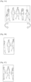
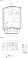
- FIGS. 1A, 1B, 1C , 1D and 1E depict an example scenario, wherein a user may not be able to capture a desired wide-angle selfie shot using a device with a fixed baseline distance according to the related art.
- the user may have to manually perform a swivel motion. If the user is unable to swivel or if there is an error in the trajectory of rotation, then the wide-angle selfie may not be captured properly.
- the field of view (FoV) of the camera(s) is limited as the baseline distance is fixed.
- the FoV or positions of the camera(s) should be adjusted by the user to capture all the subjects.
- FIGS. 1B, 1C and 1D a left view, a center view, and a right view are illustrated, respectively, which can be obtained by adjusting the position of the camera(s) by swiveling manually.
- the overlapping region, rotation, and translation between the views, can be estimated for fusing the views.
- FIG. 1E depicts the fused image, which is the final wide-angle selfie shot.
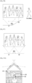
- FIGS. 2A and 2B are perspective views of an example scenario, wherein selective focus can be limited to objects at a certain depth according to various embodiments of the related art.
- FIG. 2A a preview of the cameras is depicted.
- there are multiple objects in the preview located at various depths.
- the ability to focus on an object can depend on the depth at which the object is located.
- the distance between the object and the cameras can be in a range of 0.5-1m.
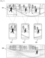
- FIG. 3 is a perspective view of an example scenario, wherein tracking of an object in motion can result in background blurring according to the related art.
- the background is likely to become blurred. This may be due to manual adjustment of the position(s) of the camera(s) to track the object in motion. The manual adjustment may be necessary as the baseline distance is fixed.
- the object is moving across a view 301, as visualized by the user.
- the user can capture a plurality of media to track the object.
- the media captured by the user's manual adjustment of the camera are illustrated in captured media 302, 303, and 304.
- the captured media (302-304) are fused, media 305 can be obtained.
- the background of the media 305 is completely blurred.
- the invention provides a method for capturing media by using a device including two bendable flaps, wherein each of the flaps includes a camera, and wherein a baseline distance can be varied by adjusting a bend angle between the flaps of the device.
- Embodiments of the disclosure disclose a method for capturing media in multiple modes using a device including at least one flap, wherein the at least one flap may include at least one camera.
- Embodiments of the disclosure may determine a field of view (FoV) of each of the cameras included in the at least one flap, and an overlap between the FoVs of the camera(s) included in the at least one flap.
- Embodiments of the disclosure may include estimating a bend angle.
- the bend angle specifies the angle between at least one flap of a device and one or more portions of the device, which can be another flap or a fixed portion of the device.
- Embodiments of the disclosure may estimate a baseline distance based on the determined bend angle. The baseline distance specifies the distance between the cameras in the different flap(s).
- a device may receive a selection of a mode for capturing media. Based on the mode selected by the user, the embodiments of the disclosure may perform an analysis of previews of the cameras in the at least one flap. Based on the analysis, an error metric may be determined, and the error metric may indicate whether the bend angle requires an adjustment for capturing the media properly. Embodiments of the disclosure may adjust the bend angle in order to nullify the error metric. The adjustment of the bend angle may determine a suitable baseline distance at which the media can be captured using the mode selected by the user.
- modes in which the media is captured may be identified based on the analysis of the previews of the cameras in the flaps.
- a corresponding error metric exists for each of the media capture modes.
- the bend angle is adjusted to nullify the error metrics, and is adjusted so as to arrive at the suitable baseline distances at which the media capturing is performed in each of the identified modes.
- FIGS. 4 through 12 where similar reference characters denote corresponding features consistently throughout the figures, there are shown preferred embodiments.
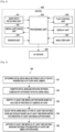
- FIG. 4 depicts various units of a device for capturing media in multiple modes according to various embodiments of the disclosure.
- a device 400 can be a flexible electronic device, including two flaps, which are bendable.
- the device 400 may include one or more portions, wherein at least one portion of the device 400 can be flipped to an open position and another portion can be static.
- Embodiments of the disclosure refer to each portion of the device 400 as a flap.
- Each flap includes a camera.
- the device 400 can be a device with a bendable display.
- the device 400 can be, but is not limited to, mobile phones, smart phones, tablets, computers, laptops, wearable computing devices, or internet of things (IoT) devices.
- the device 400 may capture media such as one or more image or one or more video.
- the device 400 may include a user input receiving unit 401, a media capturing unit 402, a sensor unit 403, a processing unit 404, an analyzer unit 405, a flap control unit 406, and a display unit 407.
- the device 400 may be connected to at least one IoT device.
- the user input receiving unit 401 may provide inputs, which have been received from a user, to the device 400.
- the user input receiving unit 401 may include, but is not limited to, at least one of the display unit 407, a touchscreen display, at least one switch, or at least one sensor.
- the user input receiving unit 401 may receive inputs from a user intending to capture media.
- the input received from the user may include a selection of a media capture mode.
- the media capture mode can be wide-angle selfie, near/far field focus, three dimensional (3D) reconstruction, object tracking, cinematic shot, panorama, and so on.
- the media capturing unit 402 can capture the media based on the received user inputs.
- the media capturing unit 402 may include at least one camera.
- the sensor unit 403 can determine an angle between the flaps of the device 400 (hereinafter referred to as initial bend angle).
- the sensor unit 403 can estimate an initial noise.
- the processing unit 404 can receive the user inputs from the user input receiving unit 401, and the initial bend angle from the sensor unit 403.
- the processing unit 404 can compute an initial baseline distance (i.e., a distance between the cameras in the flaps) based on the initial bend angle.
- the processing unit 404 can store the initial bend angle and the initial baseline distance.
- a user can select a particular media capture mode to capture the media.
- the user can indicate the selection to the device 400 through the user input receiving unit 401.
- the processing unit 404 can receive the user input. Based on the selected media capture mode, the processing unit 404 can direct the analyzer unit 405 to analyze previews of the cameras in the media capturing unit 402.
- the processing unit 404 can retrieve the previews of the cameras from the media capturing unit 402.
- the processing unit 404 can control and manage the settings of the media capturing unit 402, according to the selected media capture mode.
- the analyzer unit 405 can obtain the previews from the processing unit 404.
- the analyzer unit 405 can analyze the content of the previews of the cameras.
- the previews can include objects and/or subjects, which can be detected by the analyzer unit 405.
- the analysis of the preview can include at least one of saliency detection (if a salient object is detected), face detection (if a person is detected), eye/pupil detection, facial expression detection, object tracking (if a moving object is detected), blur detection (if occurrence of blurring is detected while capturing the moving object), determining depth and disparity of objects detected in the previews, determining registration errors (such as errors that occur when attempting to capture a cinematic shot or panorama), or pose estimation.
- the analyzer unit 405 can provide a feedback of the analysis of the previews to the processing unit 404. Based on the feedback received from the analyzer unit 405, the processing unit 404 can compute an error metric, if any.
- the error metric can depend on the media capture mode selected by the user.
- the error metric can be, for example, peak signal to noise ratio (PSNR), structural similarity (SSIM) on an overlap/stitch area, and so on.
- PSNR peak signal to noise ratio
- SSIM structural similarity
- the processing unit 404 should nullify the error metric.
- the processing unit 404 can nullify the error metric by adjusting the bend angle between the flaps. When the bend angle is adjusted, the baseline distance between cameras included in the flaps is also adjusted.
- the processing unit 404 can nullify the error metric for the selected media capture mode by detecting a suitable baseline distance corresponding to the selected media capture mode through the adjustment of the bend angle.
- the processing unit 404 can direct the flap control unit 406 to adjust the bend angle of the cameras in the flaps of the device 400, and when the baseline distance between the cameras changes according to the adjustment of the bend angle, the error metric can be nullified.
- the bend angle can be adjusted automatically by the device 400 or manually by the user.
- the device 400 can adjust the bend angle using an electronically controlled hinge mechanism or gyro angle based estimation.
- the processing unit 404 can detect a suitable baseline distance corresponding to the selected capture mode by determining whether the error metric is nullified by the adjustment of the bend angle. For instance, when the bend angle is adjusted to find the suitable baseline distance, the analyzer unit 405 can retrieve the previews from the media capturing unit 402 through the processing unit 404. The analyzer unit 405 can perform an analysis of the previews and send the feedback to the processing unit 404. The processing unit 404 can compute the error metric and confirm whether the error metric is nullified.
- the processing unit 404 can allow or direct the media capturing unit 402 to capture the media.
- the processing unit 404 can retrieve the captured media from the media capturing unit 402 and deliver the captured media to the display unit 407.
- the display unit 407 can display the captured media to the user.
- a user may not select a particular media capture mode to capture media.
- media capturing can be performed in a predefined or default media capture mode(s).
- the processing unit 404 identifies possible media capture mode(s) in which media can be captured.
- the processing unit 404 directs the analyzer unit 405 to analyze previews of the cameras.
- the processing unit 404 retrieves the previews of the cameras and sends the retrieved previews to the analyzer unit 405.
- the analyzer unit 405 can analyze the content of the previews of the cameras in the flaps of the device 400 at the initial bend angle and the initial baseline distance.
- the analyzer unit 405 can provide a feedback of the analysis of the previews to the processing unit 404.
- the processing unit 404 can identify the possible media capture mode(s), among all the predefined media capture modes, for capturing the media.
- the media can be captured. If a plurality of media capture modes is identified, then media can be captured for each of the identified media capture modes.
- the processing unit 404 can compute the error metric(s) of the media captured for each of the identified media capture mode(s). If the error metric of a particular media capture mode is nullified or less, then media can be captured in that particular media capture mode. However, if the error metric(s) is higher than a tolerable limit for the identified media capture mode(s), as computed by the processing unit 404, the error metrics should be nullified.
- the error metric(s) of the media capture mode(s) can be nullified by adjusting the bend angle between the flaps of the device 400. When the error metric of a particular media capture mode is nullified, then media can be captured in the particular media capture mode.
- a bend angle of the device 400 is adjusted such that the error metric(s) of all the identified media capture mode(s) are nullified.
- the processing unit 404 can direct the flap control unit 406 to adjust the position of the cameras (bend angle) so as to adjust the baseline distance(s), and thus the error metric(s) of all the identified media capture mode(s) are nullified.
- the processing unit 404 allows or directs the media capturing unit 402 to capture the media using the identified media capture mode(s).
- the processing unit 404 can retrieve the captured media from the media capturing unit 402 and deliver the captured media to the display unit 407.
- the display unit 407 can display the captured media to the user.
- the captured media can be of high quality.
- the device 400 is capable of reproducing scenes as viewed by the human eye, thereby providing an enhanced user experience.
- the device 400 can control the IoT device 408 through the processing unit 404.
- the sensor unit 403 can determine that the lighting is low.
- the analyzer unit 405 can obtain previews from the media capturing unit 402 and determine that the user is engaged in reading content.
- the processing unit 404 based on a feedback from the analyzer unit 405, can direct the IoT device 480 to increase the lighting in the user environment. It is assumed that the IoT device 408 can control the lighting in the user environment.
- FIG. 4 shows various units of the device 400, but it should be understood that the present disclosure is not limited thereto. According to various embodiments of the disclosure, the device 400 may include fewer or a greater number of units. Further, the labels or names of the units can be used only for illustrative purpose and do not limit the scope of the disclosure. One or more units can be combined together to perform same or substantially similar function in the device 400.
- FIG. 5 is a flowchart depicting a method for capturing media using at least one media capture mode of the device 400 according to the invention.
- the device 400 determines an initial bend angle between the flaps.
- the device 400 may compute an initial baseline distance based on the initial bend angle.
- the device 400 identifies at least one media capture mode based on an analysis of previews of the cameras included in the flaps.
- the media capture modes might be wide-angle selfie, near/far field focus, 3D reconstruction, object tracking, cinematic shot, or panorama.
- the device 400 retrieves the previews from the cameras.
- the device 400 identifies at least one media capture mode which is available in the device 400 through the analysis of the previews.
- a predefined number of media capture modes for the device 400 may exist, and based on the analysis of previews, the at least one media capture mode among the predefined number of media capture modes is identified.
- the device 400 adjusts the initial bend angle based on at least one error metric for the identified at least one media capture mode, and find at least one suitable baseline distance corresponding to the at least one media capture mode. For example, when two media capture modes are identified with respect to the device 400, the device 400 may determine the error metrics for the two media capture modes. The error metrics are determined based on the analysis of the previews. The device 400 adjusts the initial bend angle based on the determined error metrics to nullify the error metrics. According to various embodiments of the disclosure, the initial bend angle is adjusted so as to arrive at a first bend angle. The device 400 may determine whether the computed baseline distance at the first bend angle is suitable for the first media capture mode.
- the error metric corresponding to the first media capture mode can be nullified.
- the device 400 can continuously adjust the bend angle to arrive at the second bend angle.
- the device 400 can determine whether the computed baseline distance at the second bend angle is suitable for the second media capture mode.
- the error metric corresponding to the second media capture mode can be nullified.
- the device 400 can adjust the bend angle until a suitable baseline distance, at which the error metric is nullified, is to be found.
- a first media capture mode can be wide-angle selfie.
- a device 400 may perform face detection for the plurality of subjects.
- the error metric might be a subject missing or a portion of a subject missing.
- the error metric may be nullified by adjusting the bend angle in order to increase the FoV of the cameras.
- a second media capture mode can be near/far field focus.
- the device 400 may detect a plurality of objects.
- the error metric can be a lack of focus on a particular object with a certain depth. The device 400 adjusts the bend angle in order to obtain a focus on the particular object so that the error metric can be nullified.
- the device 400 captures at least one media at the at least one suitable baseline distance determined for the at least one media capture_mode. For example, the device 400 may capture a first media when the error metric corresponding to the first media capture mode is nullified. When the error metric is nullified, the first media can be captured to include all the subjects within the FoV of the cameras.
- the device 400 may capture a second media when the error metric corresponding to the second media capture mode is nullified.
- the second media can be captured to focus on the particular object.
- two suitable baseline distances are sequentially determined by continuously adjusting the bend angle.
- Each media capture mode was considered to have a single suitable baseline distance.
- multiple media capture modes may be identified, wherein each of the identified media capture modes may have multiple suitable baseline distances.
- the suitable baseline distances corresponding to different media capture modes may be determined simultaneously (i.e., a same baseline distance may be suitable for multiple media capture modes) or sequentially determined.
- the identified media capture mode has multiple suitable baseline distances (for example: cinematic shot, panorama, object tracking, etc.), media can be captured at the suitable baseline distances.
- the various actions in the method 500 may be performed in the order presented in FIG. 5 , in a different order, or simultaneously. Further, in some embodiments, some actions listed in FIG. 5 may be omitted.
- FIG. 6 is a flowchart depicting a not claimed method for capturing media, using the device 400, in a media capture mode selected by a user.
- the device 400 determines an initial bend angle between the flaps.
- the device 400 may compute an initial baseline distance based on the determined initial bend angle.
- the device 400 may perform an analysis of previews of the cameras, included in the flaps, based on the media capture mode selected by a user input. The analysis of the previews can be performed at the initial bend angle which is computed corresponding to the initial bend angle. For example, when the selected media capture mode is object tracking, the device 400 may analyze the previews at the initial baseline distance to detect objects in motion.
- the device 400 may determine an error metric based on the analysis of the previews.
- the initial baseline distance is suitable for capturing the media in the selected media capture mode, there will be no error metric.
- the device 400 may obtain at least one media by performing image capturing in the selected media capture mode at the initial baseline distance.
- the existence of the error metric may indicate that the initial baseline distance is not suitable for capturing the media in the selected media capture mode.
- the device 200 may determine whether the background is likely to be blurred when a shot is captured. The determination on whether or not blur occurs may be made based on the error metric, which corresponds to a type of the selected media capture mode.
- the device 400 may adjust the bend angle between the flaps based on the determined error metric.
- the error metric should be nullified.
- the error metric can be nullified by adjusting the bend angle.
- the baseline distance between cameras included in the flaps may be determined.
- the device 400 may determine whether the determined baseline distance is suitable for nullifying the error metric for the selected media capture mode. As the bend angle between the flaps has been adjusted, there is a possibility for finding the suitable baseline distance corresponding to the selected media capture mode. When image capturing is performed at the suitable baseline distance, the device 400 may acquire media having a good quality in the selected media capture mode. According to various embodiments of the disclosure, the device 400 may verify whether the determined baseline distance is suitable. When it is determined that the error metric for the selected media capture mode is nullified, the device 400 may determine that the determined baseline distance is suitable for the selected media capture mode.
- the device 400 may determine that the determined baseline distance is not suitable for the selected media capture mode, and perform the operation 605 again. The device 400 may continuously adjust the bend angle until a suitable baseline distance is obtained.
- the device 400 may capture the media at the determined baseline distance in the selected media capture mode. For example, when the media capture mode is object tracking, the device 400 may discover multiple suitable baseline distances at which the detected object can be captured. In relation to the respective baseline distances, the device 400 may verify the nullification of the error metric (e.g., blurring of the background) and then perform image capturing in the object tracking mode.
- the error metric e.g., blurring of the background
- Operations in the flowchart 600 may be performed in the order presented, in a different order, or simultaneously. Further, in some embodiments, some operations listed in FIG. 6 may be omitted.
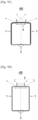
- FIGS. 7A, 7B , 7C, and 7D depicts baseline distances and FoV of cameras, which varies corresponding to adjustment of the bend angle, according to various embodiments of the disclosure.
- the device 400 may include two flaps (labeled as '1') and two cameras (labeled as '2'). Each of the two flaps may include a single camera. The angle between the flaps (labeled as '3') is the bend angle. The distance between the cameras (labeled as '4') is a baseline distance. Each camera has FoV (labeled as '5') and there is a region of overlap between the FoVs of the cameras (labeled as '6'). When the bend angle between the flaps varies, baseline distance between the cameras may vary, and the region of FoV of the cameras may overlap.
- the bend angle and the baseline distance depicted can be considered to be the initial bend angle and the initial baseline distance.
- the bend angle between the flaps is progressively varied according to various embodiments of the disclosure.
- the device 400 can be configured to capture media in a single media capture mode or multiple media capture modes. At least one suitable baseline distance corresponding to each mode can be obtained by varying the bend angle so as to arrive at a suitable bend angle. The device 400 may capture at least one media at the at least one suitable baseline distance corresponding to the media capture mode(s).
- FIG. 8 depicts a user interface (UI) for controlling a bend angle between flaps when media capturing is performed using the device 400 according to various embodiments of the disclosure.
- UI user interface
- the UI may include a plurality of buttons.
- the plurality of buttons may correspond to different multiple bend angles, respectively.
- the device 400 may adjust the bend angle to an angle corresponding to the selected button, and thus the cameras may be aligned at a particular angle at which the cameras can capture the media.
- one of the plurality of buttons can be configured to indicate the current bend angle or the range in which the current bend angle lies.
- FIGS. 9A , 9B, and 9C depict an example scenario where a wide-angle selfie is captured by varying the bend angle between the flaps of the device 400, according to various embodiments of the disclosure.
- the device 400 may include two flaps, and each flap may include a single camera.
- cameras can be labeled as C1 and C2.
- the device 400 may detect five subjects based on the analysis of the preview of C1 and C2, and determine the bend angle between the two flaps and the baseline distance at the bend angle so as to acquire media including all of the detected subjects.
- the bend angle BA1, depicted in FIG. 9A can be considered as the initial bend angle.
- the FoV of C2 is not sufficient to capture all the subjects.
- the portion of the preview which is not within the FoV of C1 and C2, can be determined as the error metric.
- the error metric should be nullified.
- the bend angle may be adjusted to arrive at a current bend angle BA2.
- the FoV of C2 may cover a greater portion of the preview, as compared to the FoV of C2 depicted in FIG. 9A .
- the device may verify whether the baseline distance according to the bend angle BA2 is suitable. In FIG. 9B , since all the detected subjects are not covered, the device may determine that the baseline distance at the bend angle BA2 is not suitable.
- the device 400 may adjust the bend angle between the flaps so that the bend angle arrives at the bend angle BA3.
- the device 400 may verify whether the baseline distance at BA3 is suitable. For example, when it is determined that the FoV of C2 at BA3 covers the entire preview, the device 400 determines that the error metric at the bend angle BA3 is nullified, and determine that the baseline distance at the bend angle BA3 is suitable for capturing the wide-angle selfie of the preview.
- FIGS. 10A , 10B, and 10C depict an example where selective focus of objects at various depths is achieved by varying the bend angle between the flaps of the device 400, according to various embodiments of the disclosure.
- the device 400 includes two flaps, and each flap includes a single camera.
- the device 400 may detect three objects at different depths based on the analysis of the previews of the cameras.
- the detected objects can be labeled as O1, O2, and O3.
- the depths of the objects may increase in the order of 01, 02, and O3.
- the device 400 may determine the bend angle and the baseline distance at the bend angle.
- the device 400 may selectively focus on O1. For attaining a Bokeh effect, the remaining objects can be blurred.
- the device 400 may adjust the bend angle between the flaps so that the bend angle arrives at the bend angle depicted in FIG. 10B .
- the device 400 can selectively focus on O2. Similarly, the device 400 may adjust the bend angle between the flaps so that the bend angle arrives at the bend angle depicted in FIG. 10C .
- the embodiments can selectively focus on O3. Once the intended objects are focused selectively, the other objects can be blurred for attaining the Bokeh effect.
- FIG. 11 depicts an example wherein the experience of augmented reality (AR) objects is visually enhanced by adjustment of bend angle between the flaps of the device, according to various embodiments of the disclosure.
- AR augmented reality
- the AR object can be an emoticon (emoji).
- the device 400 allow seamless transfer of the emoticon (labeled as 'E') from display of F1 to display of F2.
- the device 400 may display the emoticon simultaneously in F1 and F2.
- the device 400 can visualize same or different AR effects on the emoticon displayed on the displays of F1 and F2, and perform better surface scanning in AR space and a detailed rendering of the emoticon.
- FIG. 12 depicts an example where a cinematic shot is captured and an object is tracked without registration error and blurring of the background, according to the related art.
- the device 400 can automatically identify that the media capture modes having been configured in camera are a cinematic shot and object tracking.
- the media capture modes can be identified based on a user input indicating selection of either cinematic shot or object tracking.
- a plurality of suitable baseline distances may be determined by adjusting the bend angle of the flaps of the device 400.
- a plurality of shots 1201, 1202, and 1203 can be captured at the plurality of suitable baseline distances, respectively.
- the device 400 can obtain a cinematic shot 1204 by merging the captured shots 1201, 1202, and 1203.
- the cinematic shot 1204 is generated from the plurality of shots 1201, 1202, and 1203 captured at the plurality of suitable baseline distances, respectively, background blurring and registration error does not occur in the cinematic shot 1204.
- the bend angle between flaps can be adjusted automatically using electronically controlled hinge mechanism, gyro angle based estimation, and so on.
- the adjustment of the bend angle can aid in determining the suitable baseline distances.
- the embodiments disclosed in the disclosure can be implemented through at least one software program running on at least one hardware device and performing network management functions to control the network elements.
- the network elements shown in FIG. 4 include blocks which can be at least one of a hardware device, or a combination of hardware device and software module.
- the embodiments disclosed in the disclosure include a method and a device. Therefore, it is understood that the scope of the protection could be extended to such a program and in addition to a computer readable means having a message therein (which are both not claimed), such computer readable storage means contain program code means for implementation of one or more steps of the method, when the program runs on a server or mobile device or any suitable programmable device.
- a method according to various embodiments of the disclosure is implemented in a software program written in e.g. very high speed integrated circuit hardware description language (VHDL) another programming language, or implemented by one or more VHDL or several software modules being executed on at least one hardware device.
- the hardware device can be any kind of portable device that can be programmed.
- a device may also include means which could be e.g. hardware means like an application-specific integrated circuit (ASIC), or a combination of hardware and software means, e.g. an ASIC and a field programmable gate array (FPGA), or at least one microprocessor and at least one memory with software modules located therein.
- ASIC application-specific integrated circuit
- FPGA field programmable gate array
- Embodiments described herein could be implemented partly in hardware and partly in software.
- the disclosure may be implemented on different hardware devices, e.g., using a plurality of central processing units (CPUs).
- CPUs central processing units
Landscapes
- Engineering & Computer Science (AREA)
- Signal Processing (AREA)
- Multimedia (AREA)
- Human Computer Interaction (AREA)
- Physics & Mathematics (AREA)
- General Physics & Mathematics (AREA)
- Computer Vision & Pattern Recognition (AREA)
- Theoretical Computer Science (AREA)
- Studio Devices (AREA)
Description
- The disclosure relates to capturing media. More particularly, the disclosure relates to a method and a system for capturing media by using a device including a bendable display.
- Devices including a bendable display may include a plurality of flaps, in which cameras can be present. The distance between cameras in different two or more flaps among the plurality of flaps can be referred to as a baseline distance. In current devices, the baseline distance is fixed. As a result, the cameras may not be able to capture media (which can be at least one of image, video, and so on) with the desired effects or may not be able to reproduce a scene, as visualized by the user. For example, with a fixed baseline distance, the ability of the device to focus on objects at different depths can be limited. This is because the depth at which the device can focus is inversely proportional to the baseline distance, which is fixed. With a fixed baseline distance, the disparity map or depth map can be used. In another example, the efficiency of three dimensional (3D) reconstruction is likely to be minimized. With a fixed baseline distance, the capturing can be limited to planar stereo, single view point stereo, and so on.
-
US 2016/0248985 A1 discloses a method comprising obtaining a desired field of view (FOV) for an image arranged to be captured, determining a required field of view (r_fov) of the FOV for each active camera sensor of a camera array having a field of view (fov), comparing the r_fov and the fov, and determining a bend angle between adjacent camera sensors to achieve the FOV by camera sensors of the camera sensor array, if the r_fov is less than or equal to the fov. -
US 2017/0094168 A1 discloses a device for photographing a panoramic image in a foldable electronic device, wherein the electronic device may set a photographing mode and determine the folding of a housing in the photographing mode. The electronic device may acquire images from an image sensor, the photographing position of which varies according to the folding and generate a panoramic image by composing the acquired images. -
US 2017/0052566 A1 discloses a mobile terminal including a display unit disposed on a front surface and including a first portion and a second portion formed to be rotatable with respect to a boundary portion formed on one side of the first portion so as to be in a state in which the second portion covers the first portion or a state in which the second portion does not cover the first portion, a first sensing unit disposed on a left end of the terminal body and generating a first signal on the basis of a movement of the left end, a second sensing unit disposed on the right end of the terminal body and generating a second signal on the basis of a movement of the right end, and a controller controlling at least one of functions executable on the terminal on the basis of the first signal and the second signal. -
US 8,738,101 B1 discloses a multi-state detachable smartphone-tablet hybrid mobile device comprising a number of display parts connected to each other. Therein, by opening one or some of the displays, more screen space becomes available, and the smartphone is therefore converted and expanded to the tablet device. With folding the displays back, the device becomes a smartphone again. -
CN 107 820 014 A discloses a photographing method comprising the steps of setting a first camera and a second camera at different positions of a flexible screen, wherein the different positions indicate that a vertical plane of the first camera and a vertical plane of the second camera are not overlapped; obtaining a photographing angle in a photographing instruction; calculating a corresponding relationship between the photographing angle and a bending angle of the flexible screen according to a position relationship between the first camera and the second camera; and controlling the flexible screen to bend to the corresponding bending angle for photographing according to the photographing angle. -
FIGS. 1A, 1B, 1C ,1D and 1E depict an example scenario, wherein a user may not be able to capture a desired wide-angle selfie shot using a device with a fixed baseline distance according to the related art. In order to capture all the subjects in a wide-angle selfie shot, the user may have to manually perform a swivel motion. If the user is unable to swivel or if there is an error in the trajectory of rotation, then the wide-angle selfie may not be captured properly. - Referring to
FIG. 1A , the field of view (FoV) of the camera(s) is limited as the baseline distance is fixed. The FoV or positions of the camera(s) should be adjusted by the user to capture all the subjects. - Referring to
FIGS. 1B, 1C and1D , a left view, a center view, and a right view are illustrated, respectively, which can be obtained by adjusting the position of the camera(s) by swiveling manually. The overlapping region, rotation, and translation between the views, can be estimated for fusing the views. -
FIG. 1E , depicts the fused image, which is the final wide-angle selfie shot. - Referring to
FIG. 1E , a portion of some subjects is omitted due to the limited FoV of the camera(s). There can also be a possibility of artifacts, if the registration/fusion is not performed properly. -
FIGS. 2A and2B are perspective views of an example scenario, wherein selective focus can be limited to objects at a certain depth according to various embodiments of the related art. - Referring to
FIG. 2A , a preview of the cameras is depicted. As depicted inFIG. 2A , there are multiple objects in the preview, located at various depths. As the baseline distance is fixed, the ability to focus on an object can depend on the depth at which the object is located. In an example, for selective focus, the distance between the object and the cameras can be in a range of 0.5-1m. - Referring to
FIG. 2B , only the object which is nearest to the camera is selectively focused. -
FIG. 3 is a perspective view of an example scenario, wherein tracking of an object in motion can result in background blurring according to the related art. When the user attempts to track an object in motion, in the preview, while capturing media, the background is likely to become blurred. This may be due to manual adjustment of the position(s) of the camera(s) to track the object in motion. The manual adjustment may be necessary as the baseline distance is fixed. - Referring to
FIG. 3 , the object is moving across aview 301, as visualized by the user. As the object moves through theview 301, the user can capture a plurality of media to track the object. The media captured by the user's manual adjustment of the camera are illustrated in capturedmedia media 305 can be obtained. As depicted inFIG. 3 , the background of themedia 305 is completely blurred. - The above information is presented as background information only to assist with an understanding of the disclosure. No determination has been made, and no assertion is made, as to whether any of the above might be applicable as prior art with regard to the disclosure.
- The invention provides a method for capturing media by using a device including two bendable flaps, wherein each of the flaps includes a camera, and wherein a baseline distance can be varied by adjusting a bend angle between the flaps of the device.
- Aspects of the disclosure are to address at least the above-mentioned problems and/or disadvantages and to provide at least the advantages described below.
- Additional aspects will be set forth in part in the description which follows and, in part, will be apparent from the description, or may be learned by practice of the presented embodiments.
- In accordance with the invention, a method is provided as defined in the appended claims.
- In accordance with the invention, a device is provided as defined in the appended claims.
- The scope of the claimed solution is solely defined in the appended claims.
- The above and other aspects, features, and advantages of certain embodiments of the disclosure will be more apparent from the following description taken in conjunction with the accompanying drawings, in which:
-
FIGS. 1A, 1B, 1C ,1D, and 1E depict an example scenario, wherein a user may not be able to capture a desired wide-angle selfie shot using a device with a fixed baseline distance according to various embodiments of the related art; -
FIGS. 2A and2B are a perspective view of an example scenario, wherein selective focus can be limited to objects at a certain depth according to various embodiments of the related art; -
FIG. 3 is a perspective view of an example scenario, wherein tracking of an object in motion can result in background blurring according to the related art; -
FIG. 4 depicts various units of a device for capturing media in multiple media capture modes according to various embodiments of the disclosure; -
FIG. 5 is a flowchart depicting a method for capturing media using at least one media capture mode of a device according to various embodiments of the disclosure; -
FIG. 6 is a flowchart depicting a not claimed method for capturing media by using the device, in a media capture mode selected by a user input; -
FIGS. 7A, 7B ,7C, and 7D depict baseline distance and field of view (FoV) of cameras, which are changed in response to adjustment of a bend angle, according to various embodiments of the disclosure; -
FIG. 8 depicts a user interface (UI) for controlling a bend angle between flaps when media is captured by using a device according to various embodiments of the disclosure; -
FIGS. 9A ,9B, and 9C depict an example scenario where a wide-angle selfie is captured by changing a bend angle between flaps of a device according to various embodiments of the disclosure; -
FIGS. 10A ,10B, and 10C depict an example where selective focus of objects at various depths is achieved by changing a bend angle between flaps of a device, according to various embodiments of the disclosure; -
FIG. 11 depicts an example wherein the experience of Augmented Reality (AR) objects is visually enhanced by adjustment of bend angle between flaps of the device according to various embodiments of the disclosure; and -
FIG. 12 depicts an example where a cinematic shot is captured and an object is tracked without registration error and blurring of the background, according to various embodiments of the disclosure. - Throughout the drawings, like reference numerals will be understood to refer to like parts, components, and structures.
- The following description with reference to the accompanying drawings is provided to assist in a comprehensive understanding of various embodiments of the disclosure as defined by the claims and their equivalents. It includes various specific details to assist in that understanding but these are to be regarded as merely exemplary. Accordingly, those of ordinary skill in the art will recognize that various changes and modifications of the of the various embodiments described herein can be made without departing from the scope of the disclosure. In addition, descriptions of well-known functions and constructions may be omitted for clarity and conciseness.
- The terms and words used in the following description and claims are not limited to the bibliographical meanings, but, are merely used by the inventor to enable a clear and consistent understanding of the disclosure. Accordingly, it should be apparent to those skilled in the art that the following description of various embodiments of the disclosure is provided for illustration purpose only and not for the purpose of limiting the disclosure as defined by the appended claims and their equivalents.
- It is to be understood that the singular forms "a," "an," and "the" include plural referents unless the context clearly dictates otherwise. Thus, for example, reference to "a component surface" includes reference to one or more of such surfaces.
- Embodiments of the disclosure disclose a method for capturing media in multiple modes using a device including at least one flap, wherein the at least one flap may include at least one camera. Embodiments of the disclosure may determine a field of view (FoV) of each of the cameras included in the at least one flap, and an overlap between the FoVs of the camera(s) included in the at least one flap. Embodiments of the disclosure may include estimating a bend angle. Here, the bend angle specifies the angle between at least one flap of a device and one or more portions of the device, which can be another flap or a fixed portion of the device. Embodiments of the disclosure may estimate a baseline distance based on the determined bend angle. The baseline distance specifies the distance between the cameras in the different flap(s).
- According to various embodiments of the disclosure, a device may receive a selection of a mode for capturing media. Based on the mode selected by the user, the embodiments of the disclosure may perform an analysis of previews of the cameras in the at least one flap. Based on the analysis, an error metric may be determined, and the error metric may indicate whether the bend angle requires an adjustment for capturing the media properly. Embodiments of the disclosure may adjust the bend angle in order to nullify the error metric. The adjustment of the bend angle may determine a suitable baseline distance at which the media can be captured using the mode selected by the user.
- According to the invention, modes in which the media is captured may be identified based on the analysis of the previews of the cameras in the flaps. For each of the media capture modes, a corresponding error metric exists The bend angle is adjusted to nullify the error metrics, and is adjusted so as to arrive at the suitable baseline distances at which the media capturing is performed in each of the identified modes.
- Referring now to the drawings, and more particularly to
FIGS. 4 through 12 , where similar reference characters denote corresponding features consistently throughout the figures, there are shown preferred embodiments. -
FIG. 4 depicts various units of a device for capturing media in multiple modes according to various embodiments of the disclosure. Adevice 400 can be a flexible electronic device, including two flaps, which are bendable. According to an embodiment of the disclosure, thedevice 400 may include one or more portions, wherein at least one portion of thedevice 400 can be flipped to an open position and another portion can be static. Embodiments of the disclosure refer to each portion of thedevice 400 as a flap. Each flap includes a camera. In various embodiments of the disclosure, thedevice 400 can be a device with a bendable display. Thedevice 400 can be, but is not limited to, mobile phones, smart phones, tablets, computers, laptops, wearable computing devices, or internet of things (IoT) devices. Thedevice 400 may capture media such as one or more image or one or more video. - Referring to
FIG. 4 , thedevice 400 may include a userinput receiving unit 401, amedia capturing unit 402, asensor unit 403, aprocessing unit 404, ananalyzer unit 405, aflap control unit 406, and adisplay unit 407. According to an embodiment of the disclosure, thedevice 400 may be connected to at least one IoT device. - According to various embodiments of the disclosure, the user
input receiving unit 401 may provide inputs, which have been received from a user, to thedevice 400. The userinput receiving unit 401 may include, but is not limited to, at least one of thedisplay unit 407, a touchscreen display, at least one switch, or at least one sensor. The userinput receiving unit 401 may receive inputs from a user intending to capture media. In an embodiment of the disclosure, the input received from the user may include a selection of a media capture mode. In an example, the media capture mode can be wide-angle selfie, near/far field focus, three dimensional (3D) reconstruction, object tracking, cinematic shot, panorama, and so on. - The
media capturing unit 402 can capture the media based on the received user inputs. According to various embodiments of the disclosure, themedia capturing unit 402 may include at least one camera. Thesensor unit 403 can determine an angle between the flaps of the device 400 (hereinafter referred to as initial bend angle). Thesensor unit 403 can estimate an initial noise. Theprocessing unit 404 can receive the user inputs from the userinput receiving unit 401, and the initial bend angle from thesensor unit 403. Theprocessing unit 404 can compute an initial baseline distance (i.e., a distance between the cameras in the flaps) based on the initial bend angle. Theprocessing unit 404 can store the initial bend angle and the initial baseline distance. - A user can select a particular media capture mode to capture the media. The user can indicate the selection to the
device 400 through the userinput receiving unit 401. Theprocessing unit 404 can receive the user input. Based on the selected media capture mode, theprocessing unit 404 can direct theanalyzer unit 405 to analyze previews of the cameras in themedia capturing unit 402. Theprocessing unit 404 can retrieve the previews of the cameras from themedia capturing unit 402. Theprocessing unit 404 can control and manage the settings of themedia capturing unit 402, according to the selected media capture mode. - The
analyzer unit 405 can obtain the previews from theprocessing unit 404. Theanalyzer unit 405 can analyze the content of the previews of the cameras. The previews can include objects and/or subjects, which can be detected by theanalyzer unit 405. The analysis of the preview can include at least one of saliency detection (if a salient object is detected), face detection (if a person is detected), eye/pupil detection, facial expression detection, object tracking (if a moving object is detected), blur detection (if occurrence of blurring is detected while capturing the moving object), determining depth and disparity of objects detected in the previews, determining registration errors (such as errors that occur when attempting to capture a cinematic shot or panorama), or pose estimation. - The
analyzer unit 405 can provide a feedback of the analysis of the previews to theprocessing unit 404. Based on the feedback received from theanalyzer unit 405, theprocessing unit 404 can compute an error metric, if any. The error metric can depend on the media capture mode selected by the user. The error metric can be, for example, peak signal to noise ratio (PSNR), structural similarity (SSIM) on an overlap/stitch area, and so on. In order to perfectly capture the media (with a high quality), theprocessing unit 404 should nullify the error metric. Theprocessing unit 404 can nullify the error metric by adjusting the bend angle between the flaps. When the bend angle is adjusted, the baseline distance between cameras included in the flaps is also adjusted. Theprocessing unit 404 can nullify the error metric for the selected media capture mode by detecting a suitable baseline distance corresponding to the selected media capture mode through the adjustment of the bend angle. - The
processing unit 404 can direct theflap control unit 406 to adjust the bend angle of the cameras in the flaps of thedevice 400, and when the baseline distance between the cameras changes according to the adjustment of the bend angle, the error metric can be nullified. The bend angle can be adjusted automatically by thedevice 400 or manually by the user. Thedevice 400 can adjust the bend angle using an electronically controlled hinge mechanism or gyro angle based estimation. - The
processing unit 404 can detect a suitable baseline distance corresponding to the selected capture mode by determining whether the error metric is nullified by the adjustment of the bend angle. For instance, when the bend angle is adjusted to find the suitable baseline distance, theanalyzer unit 405 can retrieve the previews from themedia capturing unit 402 through theprocessing unit 404. Theanalyzer unit 405 can perform an analysis of the previews and send the feedback to theprocessing unit 404. Theprocessing unit 404 can compute the error metric and confirm whether the error metric is nullified. - When the error metric has been nullified, the
processing unit 404 can allow or direct themedia capturing unit 402 to capture the media. Theprocessing unit 404 can retrieve the captured media from themedia capturing unit 402 and deliver the captured media to thedisplay unit 407. Thedisplay unit 407 can display the captured media to the user. - In accordance with the invention, a user may not select a particular media capture mode to capture media. For example, when the user directs the
media capturing unit 402 to capture the media, media capturing can be performed in a predefined or default media capture mode(s). For another example, when the user does not select a particular media capture mode, theprocessing unit 404 identifies possible media capture mode(s) in which media can be captured. Theprocessing unit 404 directs theanalyzer unit 405 to analyze previews of the cameras. Theprocessing unit 404 retrieves the previews of the cameras and sends the retrieved previews to theanalyzer unit 405. - The
analyzer unit 405 can analyze the content of the previews of the cameras in the flaps of thedevice 400 at the initial bend angle and the initial baseline distance. Theanalyzer unit 405 can provide a feedback of the analysis of the previews to theprocessing unit 404. Based on the feedback received from theanalyzer unit 405, theprocessing unit 404 can identify the possible media capture mode(s), among all the predefined media capture modes, for capturing the media. - When the media capture mode(s) are identified, the media can be captured. If a plurality of media capture modes is identified, then media can be captured for each of the identified media capture modes. The
processing unit 404 can compute the error metric(s) of the media captured for each of the identified media capture mode(s). If the error metric of a particular media capture mode is nullified or less, then media can be captured in that particular media capture mode. However, if the error metric(s) is higher than a tolerable limit for the identified media capture mode(s), as computed by theprocessing unit 404, the error metrics should be nullified. The error metric(s) of the media capture mode(s) can be nullified by adjusting the bend angle between the flaps of thedevice 400. When the error metric of a particular media capture mode is nullified, then media can be captured in the particular media capture mode. - A bend angle of the
device 400 is adjusted such that the error metric(s) of all the identified media capture mode(s) are nullified. Theprocessing unit 404 can direct theflap control unit 406 to adjust the position of the cameras (bend angle) so as to adjust the baseline distance(s), and thus the error metric(s) of all the identified media capture mode(s) are nullified. - When the error metric(s) is nullified, the
processing unit 404 allows or directs themedia capturing unit 402 to capture the media using the identified media capture mode(s). Theprocessing unit 404 can retrieve the captured media from themedia capturing unit 402 and deliver the captured media to thedisplay unit 407. Thedisplay unit 407 can display the captured media to the user. - The captured media can be of high quality. According to various embodiments of the disclosure, the
device 400 is capable of reproducing scenes as viewed by the human eye, thereby providing an enhanced user experience. - The
device 400 can control theIoT device 408 through theprocessing unit 404. For example, consider that thedevice 400 is in an environment wherein the lighting is dim. Thesensor unit 403 can determine that the lighting is low. Theanalyzer unit 405 can obtain previews from themedia capturing unit 402 and determine that the user is engaged in reading content. In such circumstances, theprocessing unit 404, based on a feedback from theanalyzer unit 405, can direct the IoT device 480 to increase the lighting in the user environment. It is assumed that theIoT device 408 can control the lighting in the user environment. -
FIG. 4 shows various units of thedevice 400, but it should be understood that the present disclosure is not limited thereto. According to various embodiments of the disclosure, thedevice 400 may include fewer or a greater number of units. Further, the labels or names of the units can be used only for illustrative purpose and do not limit the scope of the disclosure. One or more units can be combined together to perform same or substantially similar function in thedevice 400. -
FIG. 5 is a flowchart depicting a method for capturing media using at least one media capture mode of thedevice 400 according to the invention. Atoperation 501 of themethod 500, thedevice 400 determines an initial bend angle between the flaps. Atoperation 502, thedevice 400 may compute an initial baseline distance based on the initial bend angle. - At
operation 503, thedevice 400 identifies at least one media capture mode based on an analysis of previews of the cameras included in the flaps. For example, the media capture modes might be wide-angle selfie, near/far field focus, 3D reconstruction, object tracking, cinematic shot, or panorama. Thedevice 400 retrieves the previews from the cameras. When the previews have been retrieved from the cameras, thedevice 400 identifies at least one media capture mode which is available in thedevice 400 through the analysis of the previews. A predefined number of media capture modes for thedevice 400 may exist, and based on the analysis of previews, the at least one media capture mode among the predefined number of media capture modes is identified. - At
operation 504, thedevice 400 adjusts the initial bend angle based on at least one error metric for the identified at least one media capture mode, and find at least one suitable baseline distance corresponding to the at least one media capture mode. For example, when two media capture modes are identified with respect to thedevice 400, thedevice 400 may determine the error metrics for the two media capture modes. The error metrics are determined based on the analysis of the previews. Thedevice 400 adjusts the initial bend angle based on the determined error metrics to nullify the error metrics. According to various embodiments of the disclosure, the initial bend angle is adjusted so as to arrive at a first bend angle. Thedevice 400 may determine whether the computed baseline distance at the first bend angle is suitable for the first media capture mode. When it is determined that the computed baseline distance for the first media capture mode is suitable, the error metric corresponding to the first media capture mode can be nullified. When it is determined that the computed baseline distance for the first media capture mode is not suitable, thedevice 400 can continuously adjust the bend angle to arrive at the second bend angle. Thedevice 400 can determine whether the computed baseline distance at the second bend angle is suitable for the second media capture mode. When it is determined that the computed baseline distance for the second media capture mode is suitable, the error metric corresponding to the second media capture mode can be nullified. When it is determined that the computed baseline distance for the second media capture mode is not suitable, thedevice 400 can adjust the bend angle until a suitable baseline distance, at which the error metric is nullified, is to be found. - According to various embodiments of the disclosure, a first media capture mode can be wide-angle selfie. When a plurality of subjects are detected in the previews, a
device 400 may perform face detection for the plurality of subjects. The error metric might be a subject missing or a portion of a subject missing. The error metric may be nullified by adjusting the bend angle in order to increase the FoV of the cameras. According to various embodiments of the disclosure, a second media capture mode can be near/far field focus. When the previews include multiple objects, thedevice 400 may detect a plurality of objects. The error metric can be a lack of focus on a particular object with a certain depth. Thedevice 400 adjusts the bend angle in order to obtain a focus on the particular object so that the error metric can be nullified. - At
operation 505, thedevice 400 captures at least one media at the at least one suitable baseline distance determined for the at least one media capture_mode. For example, thedevice 400 may capture a first media when the error metric corresponding to the first media capture mode is nullified. When the error metric is nullified, the first media can be captured to include all the subjects within the FoV of the cameras. - For another example, the
device 400 may capture a second media when the error metric corresponding to the second media capture mode is nullified. When the error metric is nullified, the second media can be captured to focus on the particular object. - In an embodiment of the disclosure, when two media capture modes are identified, two suitable baseline distances are sequentially determined by continuously adjusting the bend angle. Each media capture mode was considered to have a single suitable baseline distance. However, according to various embodiments of the disclosure, multiple media capture modes may be identified, wherein each of the identified media capture modes may have multiple suitable baseline distances. The suitable baseline distances corresponding to different media capture modes may be determined simultaneously (i.e., a same baseline distance may be suitable for multiple media capture modes) or sequentially determined. When the identified media capture mode has multiple suitable baseline distances (for example: cinematic shot, panorama, object tracking, etc.), media can be captured at the suitable baseline distances.
- The various actions in the
method 500 may be performed in the order presented inFIG. 5 , in a different order, or simultaneously. Further, in some embodiments, some actions listed inFIG. 5 may be omitted. -
FIG. 6 is a flowchart depicting a not claimed method for capturing media, using thedevice 400, in a media capture mode selected by a user. Atoperation 601 of themethod 600, thedevice 400 determines an initial bend angle between the flaps. Atoperation 602, thedevice 400 may compute an initial baseline distance based on the determined initial bend angle. Atoperation 603, thedevice 400 may perform an analysis of previews of the cameras, included in the flaps, based on the media capture mode selected by a user input. The analysis of the previews can be performed at the initial bend angle which is computed corresponding to the initial bend angle. For example, when the selected media capture mode is object tracking, thedevice 400 may analyze the previews at the initial baseline distance to detect objects in motion. - At
operation 604, thedevice 400 may determine an error metric based on the analysis of the previews. When the initial baseline distance is suitable for capturing the media in the selected media capture mode, there will be no error metric. When there is no error metric, thedevice 400 may obtain at least one media by performing image capturing in the selected media capture mode at the initial baseline distance. According to various embodiments of the disclosure, the existence of the error metric, however, may indicate that the initial baseline distance is not suitable for capturing the media in the selected media capture mode. For example, the device 200 may determine whether the background is likely to be blurred when a shot is captured. The determination on whether or not blur occurs may be made based on the error metric, which corresponds to a type of the selected media capture mode. - At
operation 605, thedevice 400 may adjust the bend angle between the flaps based on the determined error metric. In order to capture the media, the error metric should be nullified. The error metric can be nullified by adjusting the bend angle. When the bend angle has been adjusted, the baseline distance between cameras included in the flaps may be determined. - At
operation 606, thedevice 400 may determine whether the determined baseline distance is suitable for nullifying the error metric for the selected media capture mode. As the bend angle between the flaps has been adjusted, there is a possibility for finding the suitable baseline distance corresponding to the selected media capture mode. When image capturing is performed at the suitable baseline distance, thedevice 400 may acquire media having a good quality in the selected media capture mode. According to various embodiments of the disclosure, thedevice 400 may verify whether the determined baseline distance is suitable. When it is determined that the error metric for the selected media capture mode is nullified, thedevice 400 may determine that the determined baseline distance is suitable for the selected media capture mode. When it is determined that the error metric for the selected media capture mode is not nullified, thedevice 400 may determine that the determined baseline distance is not suitable for the selected media capture mode, and perform theoperation 605 again. Thedevice 400 may continuously adjust the bend angle until a suitable baseline distance is obtained. - When it is determined that the determined baseline distance is suitable for the selected media capture mode, at
operation 607, thedevice 400 may capture the media at the determined baseline distance in the selected media capture mode. For example, when the media capture mode is object tracking, thedevice 400 may discover multiple suitable baseline distances at which the detected object can be captured. In relation to the respective baseline distances, thedevice 400 may verify the nullification of the error metric (e.g., blurring of the background) and then perform image capturing in the object tracking mode. - Operations in the
flowchart 600 may be performed in the order presented, in a different order, or simultaneously. Further, in some embodiments, some operations listed inFIG. 6 may be omitted. -
FIGS. 7A, 7B ,7C, and 7D depicts baseline distances and FoV of cameras, which varies corresponding to adjustment of the bend angle, according to various embodiments of the disclosure. According to various embodiments of the disclosure, thedevice 400 may include two flaps (labeled as '1') and two cameras (labeled as '2'). Each of the two flaps may include a single camera. The angle between the flaps (labeled as '3') is the bend angle. The distance between the cameras (labeled as '4') is a baseline distance. Each camera has FoV (labeled as '5') and there is a region of overlap between the FoVs of the cameras (labeled as '6'). When the bend angle between the flaps varies, baseline distance between the cameras may vary, and the region of FoV of the cameras may overlap. - Referring to
FIG. 7A , the bend angle and the baseline distance depicted can be considered to be the initial bend angle and the initial baseline distance. - Referring to
FIGS. 7B to 7D , the bend angle between the flaps is progressively varied according to various embodiments of the disclosure. For example, thedevice 400 can be configured to capture media in a single media capture mode or multiple media capture modes. At least one suitable baseline distance corresponding to each mode can be obtained by varying the bend angle so as to arrive at a suitable bend angle. Thedevice 400 may capture at least one media at the at least one suitable baseline distance corresponding to the media capture mode(s). -
FIG. 8 depicts a user interface (UI) for controlling a bend angle between flaps when media capturing is performed using thedevice 400 according to various embodiments of the disclosure. - Referring to
FIG. 8 , the UI may include a plurality of buttons. The plurality of buttons may correspond to different multiple bend angles, respectively. When the user selects one of the buttons displayed on the UI, thedevice 400 may adjust the bend angle to an angle corresponding to the selected button, and thus the cameras may be aligned at a particular angle at which the cameras can capture the media. In another embodiment, one of the plurality of buttons can be configured to indicate the current bend angle or the range in which the current bend angle lies. -
FIGS. 9A ,9B, and 9C depict an example scenario where a wide-angle selfie is captured by varying the bend angle between the flaps of thedevice 400, according to various embodiments of the disclosure. Thedevice 400 may include two flaps, and each flap may include a single camera. InFIGS. 9A to 9C , cameras can be labeled as C1 and C2. Thedevice 400 may detect five subjects based on the analysis of the preview of C1 and C2, and determine the bend angle between the two flaps and the baseline distance at the bend angle so as to acquire media including all of the detected subjects. The bend angle BA1, depicted inFIG. 9A , can be considered as the initial bend angle. - Referring to
FIG. 9A , the FoV of C2 is not sufficient to capture all the subjects. InFIG. 9A , the portion of the preview, which is not within the FoV of C1 and C2, can be determined as the error metric. - In order to capture the wide-angle selfie, the error metric should be nullified. As depicted in
FIG. 9B , the bend angle may be adjusted to arrive at a current bend angle BA2. - Referring to
FIG. 9B , the FoV of C2 may cover a greater portion of the preview, as compared to the FoV of C2 depicted inFIG. 9A . The device may verify whether the baseline distance according to the bend angle BA2 is suitable. InFIG. 9B , since all the detected subjects are not covered, the device may determine that the baseline distance at the bend angle BA2 is not suitable. - Referring to
FIG. 9C , thedevice 400 may adjust the bend angle between the flaps so that the bend angle arrives at the bend angle BA3. Thedevice 400 may verify whether the baseline distance at BA3 is suitable. For example, when it is determined that the FoV of C2 at BA3 covers the entire preview, thedevice 400 determines that the error metric at the bend angle BA3 is nullified, and determine that the baseline distance at the bend angle BA3 is suitable for capturing the wide-angle selfie of the preview. -
FIGS. 10A ,10B, and 10C depict an example where selective focus of objects at various depths is achieved by varying the bend angle between the flaps of thedevice 400, according to various embodiments of the disclosure. Thedevice 400 includes two flaps, and each flap includes a single camera. Thedevice 400 may detect three objects at different depths based on the analysis of the previews of the cameras. The detected objects can be labeled as O1, O2, and O3. The depths of the objects may increase in the order of 01, 02, and O3. Thedevice 400 may determine the bend angle and the baseline distance at the bend angle. - Referring to
FIG. 10A , at the bend angle, thedevice 400 may selectively focus on O1. For attaining a Bokeh effect, the remaining objects can be blurred. Thedevice 400 may adjust the bend angle between the flaps so that the bend angle arrives at the bend angle depicted inFIG. 10B . - Referring to
FIG 10B , at the bend angle, thedevice 400 can selectively focus on O2. Similarly, thedevice 400 may adjust the bend angle between the flaps so that the bend angle arrives at the bend angle depicted inFIG. 10C . - Referring to
FIG. 10C , at the bend angle, the embodiments can selectively focus on O3. Once the intended objects are focused selectively, the other objects can be blurred for attaining the Bokeh effect. -
FIG. 11 depicts an example wherein the experience of augmented reality (AR) objects is visually enhanced by adjustment of bend angle between the flaps of the device, according to various embodiments of the disclosure. - Referring to
FIG. 11 , by adjusting the bend angle between the flaps (labeled as F1 and F2), the FoVs of the cameras in the flaps can be increased. According to various embodiments of the disclosure, the AR object can be an emoticon (emoji). Thedevice 400 allow seamless transfer of the emoticon (labeled as 'E') from display of F1 to display of F2. According to various embodiments of the disclosure, thedevice 400 may display the emoticon simultaneously in F1 and F2. Thedevice 400 can visualize same or different AR effects on the emoticon displayed on the displays of F1 and F2, and perform better surface scanning in AR space and a detailed rendering of the emoticon. -
FIG. 12 depicts an example where a cinematic shot is captured and an object is tracked without registration error and blurring of the background, according to the related art. According to various embodiments of the disclosure, thedevice 400 can automatically identify that the media capture modes having been configured in camera are a cinematic shot and object tracking. The media capture modes can be identified based on a user input indicating selection of either cinematic shot or object tracking. A plurality of suitable baseline distances may be determined by adjusting the bend angle of the flaps of thedevice 400. A plurality of shots 1201, 1202, and 1203 can be captured at the plurality of suitable baseline distances, respectively. Thedevice 400 can obtain a cinematic shot 1204 by merging the captured shots 1201, 1202, and 1203. - Referring to
FIG. 12 , since the cinematic shot 1204 is generated from the plurality of shots 1201, 1202, and 1203 captured at the plurality of suitable baseline distances, respectively, background blurring and registration error does not occur in the cinematic shot 1204. - According to various embodiments of the disclosure, when an object (labeled as O) to be tracked is detected, the bend angle between flaps can be adjusted automatically using electronically controlled hinge mechanism, gyro angle based estimation, and so on. The adjustment of the bend angle can aid in determining the suitable baseline distances.
- The embodiments disclosed in the disclosure can be implemented through at least one software program running on at least one hardware device and performing network management functions to control the network elements. The network elements shown in
FIG. 4 include blocks which can be at least one of a hardware device, or a combination of hardware device and software module. - The embodiments disclosed in the disclosure include a method and a device. Therefore, it is understood that the scope of the protection could be extended to such a program and in addition to a computer readable means having a message therein (which are both not claimed), such computer readable storage means contain program code means for implementation of one or more steps of the method, when the program runs on a server or mobile device or any suitable programmable device. A method according to various embodiments of the disclosure is implemented in a software program written in e.g. very high speed integrated circuit hardware description language (VHDL) another programming language, or implemented by one or more VHDL or several software modules being executed on at least one hardware device. The hardware device can be any kind of portable device that can be programmed. A device according to various embodiments of the disclosure may also include means which could be e.g. hardware means like an application-specific integrated circuit (ASIC), or a combination of hardware and software means, e.g. an ASIC and a field programmable gate array (FPGA), or at least one microprocessor and at least one memory with software modules located therein. Embodiments described herein could be implemented partly in hardware and partly in software. Alternatively, the disclosure may be implemented on different hardware devices, e.g., using a plurality of central processing units (CPUs).
- The scope of the claimed solution is solely defined in the appended claims.
Claims (11)
- A method for capturing a video or an image by using a device (400), the method comprising:analyzing preview images captured by each of two cameras (2), wherein each of the two cameras (2) is included in a respective one of two flaps (1) of the device (400);identifying at least one capture mode from a plurality of capture modes based on an analysis of the preview images, the plurality of capture modes including wide-angle selfie, near/far field focus, 3D reconstruction, object tracking, cinematic shot, and panorama;adjusting a bend angle (3) between the two flaps (1) based on an error metric for the identified capture mode, wherein the error metric is a criterion indicating whether the bend angle is appropriate for the identified capture mode and wherein a corresponding error metric exists for each of the capture modes;determining a baseline distance (4) indicating a distance between the two cameras (2) based on the adjusted bend angle; andobtaining the video or the image in the identified capture mode at the determined baseline distance (4), andwherein the adjusting of the bend angle (3) comprises adjusting the bend angle (3) between the two flaps until the error metric is nullified.
- The method of claim 1, wherein the preview images are captured at an initial bend angle between the cameras (2).
- The method of claim 1, further comprising automatically adjusting the bend angle (3).
- The method of claim 1, wherein the determining of the baseline distance (4) comprises:computing the error metric for the identified capture mode based on the analyzing of the preview images captured by each of the cameras (2);adjusting the bend angle (3) to a first angle (3) by changing a position of a first flap (1) among the two flaps (1);analyzing the preview images captured by each of the cameras (2) at a first baseline distance (4) according to the first angle (3); anddetermining whether the error metric for the identified capture mode is nullified, based on the analyzed preview images at the first baseline distance (4).
- The method of claim 4, further comprising, in response to determining that the error metric for the identified capture mode is nullified, determining the first baseline distance (4) as a baseline distance (4) corresponding to the identified capture mode.
- The method of claim 4, further comprising:adjusting the bend angle (3) to a second bend angle (3) in response to determining that the error metric for the identified capture mode is not nullified;analyzing the preview images captured by each of the cameras (2) at a second baseline distance (4) according to the second bend angle (3);determining whether the error metric for the identified capture mode is nullified, based on the analyzed preview images at the second baseline distance (4); anddetermining, as a baseline distance (4) corresponding to the identified capture mode, the second baseline distance (4) at which the error metric for the identified capture mode is nullified.
- A device (400) for capturing a video or an image, the device (400) comprising:two flaps (1), wherein each of the flaps (1) includes a camera (2); anda processor (404) configured to:analyze preview images captured by each of the cameras (2),identify at least one capture mode from a plurality of capture modes based on an analysis of the preview images, the plurality of capture modes including wide-angle selfie, near/far field focus, 3D reconstruction, object tracking, cinematic shot, and panorama,adjust a bend angle (3) between the two flaps (1) based on an error metric for the identified capture mode, wherein the error metric is a criterion indicating whether the bend angle is appropriate for the identified capture mode and wherein a corresponding error metric exists for each of the capture modes,determine a baseline distance (4) indicating a distance between the two cameras (2) based on the adjusted bend angle, andobtain the video or the image in the identified capture mode at the determined baseline distance (4), andwherein the adjusting of the bend angle (3) comprises adjusting the bend angle (3) between the two flaps until the error metric is nullified.
- The device (400) as of claim 7, further comprising a flap controller (406) for adjusting the bend angle (3),
wherein the preview images are captured at an initial bend angle (3) between the cameras (2). - The device (400) of claim 7, wherein the processor (404) is further configured to:compute the error metric for the identified capture mode based on the analyzing of the preview images captured by each of the cameras (2),adjust the bend angle (3) to a first angle (3) by changing a position of a first flap (1) among the two flaps (1),analyze the preview images captured by each of the cameras (2) based on the first baseline distance (4) according to the first angle (3), anddetermine whether the error metric for the identified capture mode is nullified, based on the analyzed preview images at the first baseline distance (4).
- The device (400) of claim 9, wherein, in response to determining that the error metric for the identified capture mode is nullified, the processor (404) is further configured to determine the first baseline distance (4) as a baseline distance (4) corresponding to the identified capture mode.
- The device (400) of claim 9, wherein the processor (404) is further configured to:adjust the bend angle (3) to a second bend angle (3) in response to determining that the error metric for the identified capture mode is not nullified;analyze the preview images captured by each of the cameras (2) at a second baseline distance (4) according to the second bend angle (3);determine whether the error metric for the identified capture mode is nullified, based on the analyzed preview images at the second baseline distance (4); anddetermine, as a baseline distance (4) corresponding to the identified capture mode, the second baseline distance (4) at which the error metric for the identified capture mode is nullified.
Applications Claiming Priority (3)
| Application Number | Priority Date | Filing Date | Title |
|---|---|---|---|
| IN201841025398 | 2018-07-06 | ||
| KR1020190072492A KR102835887B1 (en) | 2018-07-06 | 2019-06-18 | Electronic device for capturing media using a bendable display and method thereof |
| PCT/KR2019/008323 WO2020009543A1 (en) | 2018-07-06 | 2019-07-05 | Electronic device for capturing media using a bendable display and method thereof |
Publications (3)
| Publication Number | Publication Date |
|---|---|
| EP3794814A1 EP3794814A1 (en) | 2021-03-24 |
| EP3794814A4 EP3794814A4 (en) | 2021-06-23 |
| EP3794814B1 true EP3794814B1 (en) | 2024-03-20 |
Family
ID=69156551
Family Applications (1)
| Application Number | Title | Priority Date | Filing Date |
|---|---|---|---|
| EP19830787.8A Active EP3794814B1 (en) | 2018-07-06 | 2019-07-05 | Electronic device for capturing media using a bendable display and method thereof |
Country Status (3)
| Country | Link |
|---|---|
| EP (1) | EP3794814B1 (en) |
| KR (1) | KR102835887B1 (en) |
| CN (1) | CN112400312A (en) |
Citations (1)
| Publication number | Priority date | Publication date | Assignee | Title |
|---|---|---|---|---|
| CN107820014A (en) * | 2017-11-27 | 2018-03-20 | 努比亚技术有限公司 | A kind of image pickup method, mobile terminal and computer-readable storage medium |
Family Cites Families (10)
| Publication number | Priority date | Publication date | Assignee | Title |
|---|---|---|---|---|
| US8738101B1 (en) * | 2013-02-06 | 2014-05-27 | Makor Issues And Rights Ltd. | Smartphone-tablet hybrid device |
| KR101632008B1 (en) * | 2014-04-30 | 2016-07-01 | 엘지전자 주식회사 | Mobile terminal and method for controlling the same |
| KR102223281B1 (en) | 2014-07-23 | 2021-03-05 | 엘지전자 주식회사 | Mobile terminal and method for controlling the same |
| JP6525537B2 (en) * | 2014-09-30 | 2019-06-05 | キヤノン株式会社 | IMAGE PROCESSING APPARATUS, CONTROL METHOD THEREOF, PROGRAM, AND STORAGE MEDIUM |
| CN106471803A (en) * | 2014-12-04 | 2017-03-01 | 深圳市大疆创新科技有限公司 | Imaging system and method |
| GB2535706A (en) * | 2015-02-24 | 2016-08-31 | Nokia Technologies Oy | Device with an adaptive camera array |
| KR102391497B1 (en) * | 2015-09-30 | 2022-04-28 | 삼성전자주식회사 | Apparatus and method for proecessing an image in electronic device |
| EP3206163B1 (en) * | 2016-02-11 | 2018-12-26 | AR4 GmbH | Image processing method, mobile device and method for generating a video image database |
| US10593065B2 (en) * | 2016-07-27 | 2020-03-17 | Htc Corporation | Method and device for camera pose estimation |
| CN107682634A (en) * | 2017-10-18 | 2018-02-09 | 维沃移动通信有限公司 | A kind of facial image acquisition methods and mobile terminal |
-
2019
- 2019-06-18 KR KR1020190072492A patent/KR102835887B1/en active Active
- 2019-07-05 CN CN201980045246.1A patent/CN112400312A/en active Pending
- 2019-07-05 EP EP19830787.8A patent/EP3794814B1/en active Active
Patent Citations (1)
| Publication number | Priority date | Publication date | Assignee | Title |
|---|---|---|---|---|
| CN107820014A (en) * | 2017-11-27 | 2018-03-20 | 努比亚技术有限公司 | A kind of image pickup method, mobile terminal and computer-readable storage medium |
Also Published As
| Publication number | Publication date |
|---|---|
| KR102835887B1 (en) | 2025-07-21 |
| EP3794814A4 (en) | 2021-06-23 |
| KR20200005440A (en) | 2020-01-15 |
| CN112400312A (en) | 2021-02-23 |
| EP3794814A1 (en) | 2021-03-24 |
Similar Documents
| Publication | Publication Date | Title |
|---|---|---|
| US11057553B2 (en) | Electronic device for capturing media using a bendable display and method thereof | |
| CN109313799B (en) | Image processing method and device | |
| KR102187146B1 (en) | Dual-aperture zoom digital camera with automatic adjustable tele field of view | |
| US9282242B2 (en) | Method and electric device for taking panoramic photograph | |
| CN106464803B (en) | Enhanced image capture | |
| CN106165391B (en) | Enhanced Image Capture | |
| CN104902170B (en) | A camera method and terminal | |
| EP2993894B1 (en) | Image capturing method and electronic apparatus | |
| US20170316582A1 (en) | Robust Head Pose Estimation with a Depth Camera | |
| CN115086547A (en) | Image pickup apparatus, portable device, calibrator, control method thereof, and storage medium | |
| KR20150050172A (en) | Apparatus and Method for Selecting Multi-Camera Dynamically to Track Interested Object | |
| GB2407635A (en) | Control of camera field of view with user hand gestures recognition | |
| KR20140009489A (en) | Positional sensor-assisted image registration for panoramic photography | |
| KR102155895B1 (en) | Device and method to receive image by tracking object | |
| EP3808063B1 (en) | Electronic device and method for capturing a view | |
| US10764493B2 (en) | Display method and electronic device | |
| US10958825B2 (en) | Electronic apparatus and method for controlling the same | |
| CN109451240B (en) | Focusing method, focusing device, computer equipment and readable storage medium | |
| CN110785995A (en) | Shooting control method, device, device and storage medium | |
| CN114641983A (en) | System and method for obtaining intelligent panoramic image | |
| CN110290299B (en) | Imaging method, apparatus, storage medium and electronic device | |
| CN105049719A (en) | Panoramic shooting method and mobile terminal | |
| WO2025151726A1 (en) | Systems, methods, and apparatuses for a stable superzoom | |
| TW202011349A (en) | Method and system for rendering a panoramic image | |
| KR102835887B1 (en) | Electronic device for capturing media using a bendable display and method thereof |
Legal Events
| Date | Code | Title | Description |
|---|---|---|---|
| STAA | Information on the status of an ep patent application or granted ep patent |
Free format text: STATUS: THE INTERNATIONAL PUBLICATION HAS BEEN MADE |
|
| PUAI | Public reference made under article 153(3) epc to a published international application that has entered the european phase |
Free format text: ORIGINAL CODE: 0009012 |
|
| STAA | Information on the status of an ep patent application or granted ep patent |
Free format text: STATUS: REQUEST FOR EXAMINATION WAS MADE |
|
| 17P | Request for examination filed |
Effective date: 20201214 |
|
| AK | Designated contracting states |
Kind code of ref document: A1 Designated state(s): AL AT BE BG CH CY CZ DE DK EE ES FI FR GB GR HR HU IE IS IT LI LT LU LV MC MK MT NL NO PL PT RO RS SE SI SK SM TR |
|
| AX | Request for extension of the european patent |
Extension state: BA ME |
|
| A4 | Supplementary search report drawn up and despatched |
Effective date: 20210521 |
|
| RIC1 | Information provided on ipc code assigned before grant |
Ipc: H04N 5/232 20060101AFI20210517BHEP Ipc: H04N 5/225 20060101ALI20210517BHEP Ipc: G03B 17/04 20210101ALI20210517BHEP Ipc: H04M 1/02 20060101ALI20210517BHEP Ipc: H04N 5/262 20060101ALI20210517BHEP |
|
| DAV | Request for validation of the european patent (deleted) | ||
| DAX | Request for extension of the european patent (deleted) | ||
| STAA | Information on the status of an ep patent application or granted ep patent |
Free format text: STATUS: EXAMINATION IS IN PROGRESS |
|
| 17Q | First examination report despatched |
Effective date: 20220923 |
|
| REG | Reference to a national code |
Ref country code: DE Ref legal event code: R079 Free format text: PREVIOUS MAIN CLASS: H04N0005232000 Ipc: H04M0001020000 Ref country code: DE Ref legal event code: R079 Ref document number: 602019048726 Country of ref document: DE Free format text: PREVIOUS MAIN CLASS: H04N0005232000 Ipc: H04M0001020000 |
|
| RIC1 | Information provided on ipc code assigned before grant |
Ipc: H04N 23/80 20230101ALI20231026BHEP Ipc: H04N 23/667 20230101ALI20231026BHEP Ipc: H04N 23/60 20230101ALI20231026BHEP Ipc: H04N 23/51 20230101ALI20231026BHEP Ipc: H04N 23/45 20230101ALI20231026BHEP Ipc: H04N 5/262 20060101ALI20231026BHEP Ipc: H04M 1/02 20060101AFI20231026BHEP |
|
| GRAP | Despatch of communication of intention to grant a patent |
Free format text: ORIGINAL CODE: EPIDOSNIGR1 |
|
| STAA | Information on the status of an ep patent application or granted ep patent |
Free format text: STATUS: GRANT OF PATENT IS INTENDED |
|
| INTG | Intention to grant announced |
Effective date: 20231201 |
|
| GRAS | Grant fee paid |
Free format text: ORIGINAL CODE: EPIDOSNIGR3 |
|
| GRAA | (expected) grant |
Free format text: ORIGINAL CODE: 0009210 |
|
| STAA | Information on the status of an ep patent application or granted ep patent |
Free format text: STATUS: THE PATENT HAS BEEN GRANTED |
|
| AK | Designated contracting states |
Kind code of ref document: B1 Designated state(s): AL AT BE BG CH CY CZ DE DK EE ES FI FR GB GR HR HU IE IS IT LI LT LU LV MC MK MT NL NO PL PT RO RS SE SI SK SM TR |
|
| REG | Reference to a national code |
Ref country code: GB Ref legal event code: FG4D |
|
| REG | Reference to a national code |
Ref country code: CH Ref legal event code: EP |
|
| REG | Reference to a national code |
Ref country code: IE Ref legal event code: FG4D |
|
| REG | Reference to a national code |
Ref country code: DE Ref legal event code: R096 Ref document number: 602019048726 Country of ref document: DE |
|
| PG25 | Lapsed in a contracting state [announced via postgrant information from national office to epo] |
Ref country code: LT Free format text: LAPSE BECAUSE OF FAILURE TO SUBMIT A TRANSLATION OF THE DESCRIPTION OR TO PAY THE FEE WITHIN THE PRESCRIBED TIME-LIMIT Effective date: 20240320 |
|
| REG | Reference to a national code |
Ref country code: LT Ref legal event code: MG9D |
|
| PG25 | Lapsed in a contracting state [announced via postgrant information from national office to epo] |
Ref country code: GR Free format text: LAPSE BECAUSE OF FAILURE TO SUBMIT A TRANSLATION OF THE DESCRIPTION OR TO PAY THE FEE WITHIN THE PRESCRIBED TIME-LIMIT Effective date: 20240621 |
|
| PG25 | Lapsed in a contracting state [announced via postgrant information from national office to epo] |
Ref country code: HR Free format text: LAPSE BECAUSE OF FAILURE TO SUBMIT A TRANSLATION OF THE DESCRIPTION OR TO PAY THE FEE WITHIN THE PRESCRIBED TIME-LIMIT Effective date: 20240320 Ref country code: RS Free format text: LAPSE BECAUSE OF FAILURE TO SUBMIT A TRANSLATION OF THE DESCRIPTION OR TO PAY THE FEE WITHIN THE PRESCRIBED TIME-LIMIT Effective date: 20240620 |
|
| REG | Reference to a national code |
Ref country code: NL Ref legal event code: MP Effective date: 20240320 |
|
| PG25 | Lapsed in a contracting state [announced via postgrant information from national office to epo] |
Ref country code: RS Free format text: LAPSE BECAUSE OF FAILURE TO SUBMIT A TRANSLATION OF THE DESCRIPTION OR TO PAY THE FEE WITHIN THE PRESCRIBED TIME-LIMIT Effective date: 20240620 Ref country code: NO Free format text: LAPSE BECAUSE OF FAILURE TO SUBMIT A TRANSLATION OF THE DESCRIPTION OR TO PAY THE FEE WITHIN THE PRESCRIBED TIME-LIMIT Effective date: 20240620 Ref country code: LT Free format text: LAPSE BECAUSE OF FAILURE TO SUBMIT A TRANSLATION OF THE DESCRIPTION OR TO PAY THE FEE WITHIN THE PRESCRIBED TIME-LIMIT Effective date: 20240320 Ref country code: HR Free format text: LAPSE BECAUSE OF FAILURE TO SUBMIT A TRANSLATION OF THE DESCRIPTION OR TO PAY THE FEE WITHIN THE PRESCRIBED TIME-LIMIT Effective date: 20240320 Ref country code: GR Free format text: LAPSE BECAUSE OF FAILURE TO SUBMIT A TRANSLATION OF THE DESCRIPTION OR TO PAY THE FEE WITHIN THE PRESCRIBED TIME-LIMIT Effective date: 20240621 Ref country code: FI Free format text: LAPSE BECAUSE OF FAILURE TO SUBMIT A TRANSLATION OF THE DESCRIPTION OR TO PAY THE FEE WITHIN THE PRESCRIBED TIME-LIMIT Effective date: 20240320 Ref country code: BG Free format text: LAPSE BECAUSE OF FAILURE TO SUBMIT A TRANSLATION OF THE DESCRIPTION OR TO PAY THE FEE WITHIN THE PRESCRIBED TIME-LIMIT Effective date: 20240320 |
|
| REG | Reference to a national code |
Ref country code: AT Ref legal event code: MK05 Ref document number: 1668830 Country of ref document: AT Kind code of ref document: T Effective date: 20240320 |
|
| PG25 | Lapsed in a contracting state [announced via postgrant information from national office to epo] |
Ref country code: SE Free format text: LAPSE BECAUSE OF FAILURE TO SUBMIT A TRANSLATION OF THE DESCRIPTION OR TO PAY THE FEE WITHIN THE PRESCRIBED TIME-LIMIT Effective date: 20240320 Ref country code: LV Free format text: LAPSE BECAUSE OF FAILURE TO SUBMIT A TRANSLATION OF THE DESCRIPTION OR TO PAY THE FEE WITHIN THE PRESCRIBED TIME-LIMIT Effective date: 20240320 |
|
| PG25 | Lapsed in a contracting state [announced via postgrant information from national office to epo] |
Ref country code: NL Free format text: LAPSE BECAUSE OF FAILURE TO SUBMIT A TRANSLATION OF THE DESCRIPTION OR TO PAY THE FEE WITHIN THE PRESCRIBED TIME-LIMIT Effective date: 20240320 |
|
| PG25 | Lapsed in a contracting state [announced via postgrant information from national office to epo] |
Ref country code: NL Free format text: LAPSE BECAUSE OF FAILURE TO SUBMIT A TRANSLATION OF THE DESCRIPTION OR TO PAY THE FEE WITHIN THE PRESCRIBED TIME-LIMIT Effective date: 20240320 |
|
| PG25 | Lapsed in a contracting state [announced via postgrant information from national office to epo] |
Ref country code: IS Free format text: LAPSE BECAUSE OF FAILURE TO SUBMIT A TRANSLATION OF THE DESCRIPTION OR TO PAY THE FEE WITHIN THE PRESCRIBED TIME-LIMIT Effective date: 20240720 |
|
| PG25 | Lapsed in a contracting state [announced via postgrant information from national office to epo] |
Ref country code: PT Free format text: LAPSE BECAUSE OF FAILURE TO SUBMIT A TRANSLATION OF THE DESCRIPTION OR TO PAY THE FEE WITHIN THE PRESCRIBED TIME-LIMIT Effective date: 20240722 Ref country code: SM Free format text: LAPSE BECAUSE OF FAILURE TO SUBMIT A TRANSLATION OF THE DESCRIPTION OR TO PAY THE FEE WITHIN THE PRESCRIBED TIME-LIMIT Effective date: 20240320 |
|
| PG25 | Lapsed in a contracting state [announced via postgrant information from national office to epo] |
Ref country code: ES Free format text: LAPSE BECAUSE OF FAILURE TO SUBMIT A TRANSLATION OF THE DESCRIPTION OR TO PAY THE FEE WITHIN THE PRESCRIBED TIME-LIMIT Effective date: 20240320 |
|
| PG25 | Lapsed in a contracting state [announced via postgrant information from national office to epo] |
Ref country code: EE Free format text: LAPSE BECAUSE OF FAILURE TO SUBMIT A TRANSLATION OF THE DESCRIPTION OR TO PAY THE FEE WITHIN THE PRESCRIBED TIME-LIMIT Effective date: 20240320 Ref country code: CZ Free format text: LAPSE BECAUSE OF FAILURE TO SUBMIT A TRANSLATION OF THE DESCRIPTION OR TO PAY THE FEE WITHIN THE PRESCRIBED TIME-LIMIT Effective date: 20240320 |
|
| PG25 | Lapsed in a contracting state [announced via postgrant information from national office to epo] |
Ref country code: AT Free format text: LAPSE BECAUSE OF FAILURE TO SUBMIT A TRANSLATION OF THE DESCRIPTION OR TO PAY THE FEE WITHIN THE PRESCRIBED TIME-LIMIT Effective date: 20240320 |
|
| PG25 | Lapsed in a contracting state [announced via postgrant information from national office to epo] |
Ref country code: PL Free format text: LAPSE BECAUSE OF FAILURE TO SUBMIT A TRANSLATION OF THE DESCRIPTION OR TO PAY THE FEE WITHIN THE PRESCRIBED TIME-LIMIT Effective date: 20240320 |
|
| PG25 | Lapsed in a contracting state [announced via postgrant information from national office to epo] |
Ref country code: SK Free format text: LAPSE BECAUSE OF FAILURE TO SUBMIT A TRANSLATION OF THE DESCRIPTION OR TO PAY THE FEE WITHIN THE PRESCRIBED TIME-LIMIT Effective date: 20240320 |
|
| PG25 | Lapsed in a contracting state [announced via postgrant information from national office to epo] |
Ref country code: SM Free format text: LAPSE BECAUSE OF FAILURE TO SUBMIT A TRANSLATION OF THE DESCRIPTION OR TO PAY THE FEE WITHIN THE PRESCRIBED TIME-LIMIT Effective date: 20240320 Ref country code: SK Free format text: LAPSE BECAUSE OF FAILURE TO SUBMIT A TRANSLATION OF THE DESCRIPTION OR TO PAY THE FEE WITHIN THE PRESCRIBED TIME-LIMIT Effective date: 20240320 Ref country code: RO Free format text: LAPSE BECAUSE OF FAILURE TO SUBMIT A TRANSLATION OF THE DESCRIPTION OR TO PAY THE FEE WITHIN THE PRESCRIBED TIME-LIMIT Effective date: 20240320 Ref country code: PT Free format text: LAPSE BECAUSE OF FAILURE TO SUBMIT A TRANSLATION OF THE DESCRIPTION OR TO PAY THE FEE WITHIN THE PRESCRIBED TIME-LIMIT Effective date: 20240722 Ref country code: PL Free format text: LAPSE BECAUSE OF FAILURE TO SUBMIT A TRANSLATION OF THE DESCRIPTION OR TO PAY THE FEE WITHIN THE PRESCRIBED TIME-LIMIT Effective date: 20240320 Ref country code: IS Free format text: LAPSE BECAUSE OF FAILURE TO SUBMIT A TRANSLATION OF THE DESCRIPTION OR TO PAY THE FEE WITHIN THE PRESCRIBED TIME-LIMIT Effective date: 20240720 Ref country code: ES Free format text: LAPSE BECAUSE OF FAILURE TO SUBMIT A TRANSLATION OF THE DESCRIPTION OR TO PAY THE FEE WITHIN THE PRESCRIBED TIME-LIMIT Effective date: 20240320 Ref country code: EE Free format text: LAPSE BECAUSE OF FAILURE TO SUBMIT A TRANSLATION OF THE DESCRIPTION OR TO PAY THE FEE WITHIN THE PRESCRIBED TIME-LIMIT Effective date: 20240320 Ref country code: CZ Free format text: LAPSE BECAUSE OF FAILURE TO SUBMIT A TRANSLATION OF THE DESCRIPTION OR TO PAY THE FEE WITHIN THE PRESCRIBED TIME-LIMIT Effective date: 20240320 Ref country code: AT Free format text: LAPSE BECAUSE OF FAILURE TO SUBMIT A TRANSLATION OF THE DESCRIPTION OR TO PAY THE FEE WITHIN THE PRESCRIBED TIME-LIMIT Effective date: 20240320 |
|
| PG25 | Lapsed in a contracting state [announced via postgrant information from national office to epo] |
Ref country code: IT Free format text: LAPSE BECAUSE OF FAILURE TO SUBMIT A TRANSLATION OF THE DESCRIPTION OR TO PAY THE FEE WITHIN THE PRESCRIBED TIME-LIMIT Effective date: 20240320 |
|
| REG | Reference to a national code |
Ref country code: DE Ref legal event code: R097 Ref document number: 602019048726 Country of ref document: DE |
|
| PG25 | Lapsed in a contracting state [announced via postgrant information from national office to epo] |
Ref country code: IT Free format text: LAPSE BECAUSE OF FAILURE TO SUBMIT A TRANSLATION OF THE DESCRIPTION OR TO PAY THE FEE WITHIN THE PRESCRIBED TIME-LIMIT Effective date: 20240320 |
|
| PG25 | Lapsed in a contracting state [announced via postgrant information from national office to epo] |
Ref country code: DK Free format text: LAPSE BECAUSE OF FAILURE TO SUBMIT A TRANSLATION OF THE DESCRIPTION OR TO PAY THE FEE WITHIN THE PRESCRIBED TIME-LIMIT Effective date: 20240320 |
|
| PLBE | No opposition filed within time limit |
Free format text: ORIGINAL CODE: 0009261 |
|
| STAA | Information on the status of an ep patent application or granted ep patent |
Free format text: STATUS: NO OPPOSITION FILED WITHIN TIME LIMIT |
|
| PG25 | Lapsed in a contracting state [announced via postgrant information from national office to epo] |
Ref country code: DK Free format text: LAPSE BECAUSE OF FAILURE TO SUBMIT A TRANSLATION OF THE DESCRIPTION OR TO PAY THE FEE WITHIN THE PRESCRIBED TIME-LIMIT Effective date: 20240320 |
|
| PG25 | Lapsed in a contracting state [announced via postgrant information from national office to epo] |
Ref country code: MC Free format text: LAPSE BECAUSE OF FAILURE TO SUBMIT A TRANSLATION OF THE DESCRIPTION OR TO PAY THE FEE WITHIN THE PRESCRIBED TIME-LIMIT Effective date: 20240320 |
|
| 26N | No opposition filed |
Effective date: 20241223 |
|
| REG | Reference to a national code |
Ref country code: CH Ref legal event code: PL |
|
| PG25 | Lapsed in a contracting state [announced via postgrant information from national office to epo] |
Ref country code: LU Free format text: LAPSE BECAUSE OF NON-PAYMENT OF DUE FEES Effective date: 20240705 |
|
| PG25 | Lapsed in a contracting state [announced via postgrant information from national office to epo] |
Ref country code: LU Free format text: LAPSE BECAUSE OF NON-PAYMENT OF DUE FEES Effective date: 20240705 |
|
| PG25 | Lapsed in a contracting state [announced via postgrant information from national office to epo] |
Ref country code: CH Free format text: LAPSE BECAUSE OF NON-PAYMENT OF DUE FEES Effective date: 20240731 Ref country code: BE Free format text: LAPSE BECAUSE OF NON-PAYMENT OF DUE FEES Effective date: 20240731 Ref country code: SI Free format text: LAPSE BECAUSE OF FAILURE TO SUBMIT A TRANSLATION OF THE DESCRIPTION OR TO PAY THE FEE WITHIN THE PRESCRIBED TIME-LIMIT Effective date: 20240320 |
|
| PG25 | Lapsed in a contracting state [announced via postgrant information from national office to epo] |
Ref country code: FR Free format text: LAPSE BECAUSE OF NON-PAYMENT OF DUE FEES Effective date: 20240731 |
|
| REG | Reference to a national code |
Ref country code: BE Ref legal event code: MM Effective date: 20240731 |
|
| PGFP | Annual fee paid to national office [announced via postgrant information from national office to epo] |
Ref country code: GB Payment date: 20250624 Year of fee payment: 7 |
|
| PG25 | Lapsed in a contracting state [announced via postgrant information from national office to epo] |
Ref country code: IE Free format text: LAPSE BECAUSE OF NON-PAYMENT OF DUE FEES Effective date: 20240705 |
|
| PGFP | Annual fee paid to national office [announced via postgrant information from national office to epo] |
Ref country code: DE Payment date: 20250624 Year of fee payment: 7 |
|
| PG25 | Lapsed in a contracting state [announced via postgrant information from national office to epo] |
Ref country code: CY Free format text: LAPSE BECAUSE OF FAILURE TO SUBMIT A TRANSLATION OF THE DESCRIPTION OR TO PAY THE FEE WITHIN THE PRESCRIBED TIME-LIMIT; INVALID AB INITIO Effective date: 20190705 |
|
| PG25 | Lapsed in a contracting state [announced via postgrant information from national office to epo] |
Ref country code: HU Free format text: LAPSE BECAUSE OF FAILURE TO SUBMIT A TRANSLATION OF THE DESCRIPTION OR TO PAY THE FEE WITHIN THE PRESCRIBED TIME-LIMIT; INVALID AB INITIO Effective date: 20190705 |