EP3794585B1 - Real-time detection of feedforward instability - Google Patents
Real-time detection of feedforward instability Download PDFInfo
- Publication number
- EP3794585B1 EP3794585B1 EP19727263.6A EP19727263A EP3794585B1 EP 3794585 B1 EP3794585 B1 EP 3794585B1 EP 19727263 A EP19727263 A EP 19727263A EP 3794585 B1 EP3794585 B1 EP 3794585B1
- Authority
- EP
- European Patent Office
- Prior art keywords
- signal
- instability
- feedforward
- response
- phase
- Prior art date
- Legal status (The legal status is an assumption and is not a legal conclusion. Google has not performed a legal analysis and makes no representation as to the accuracy of the status listed.)
- Active
Links
Images


Classifications
-
- G—PHYSICS
- G10—MUSICAL INSTRUMENTS; ACOUSTICS
- G10K—SOUND-PRODUCING DEVICES; METHODS OR DEVICES FOR PROTECTING AGAINST, OR FOR DAMPING, NOISE OR OTHER ACOUSTIC WAVES IN GENERAL; ACOUSTICS NOT OTHERWISE PROVIDED FOR
- G10K11/00—Methods or devices for transmitting, conducting or directing sound in general; Methods or devices for protecting against, or for damping, noise or other acoustic waves in general
- G10K11/16—Methods or devices for protecting against, or for damping, noise or other acoustic waves in general
- G10K11/175—Methods or devices for protecting against, or for damping, noise or other acoustic waves in general using interference effects; Masking sound
- G10K11/178—Methods or devices for protecting against, or for damping, noise or other acoustic waves in general using interference effects; Masking sound by electro-acoustically regenerating the original acoustic waves in anti-phase
- G10K11/1787—General system configurations
- G10K11/17873—General system configurations using a reference signal without an error signal, e.g. pure feedforward
-
- G—PHYSICS
- G10—MUSICAL INSTRUMENTS; ACOUSTICS
- G10K—SOUND-PRODUCING DEVICES; METHODS OR DEVICES FOR PROTECTING AGAINST, OR FOR DAMPING, NOISE OR OTHER ACOUSTIC WAVES IN GENERAL; ACOUSTICS NOT OTHERWISE PROVIDED FOR
- G10K11/00—Methods or devices for transmitting, conducting or directing sound in general; Methods or devices for protecting against, or for damping, noise or other acoustic waves in general
- G10K11/16—Methods or devices for protecting against, or for damping, noise or other acoustic waves in general
- G10K11/175—Methods or devices for protecting against, or for damping, noise or other acoustic waves in general using interference effects; Masking sound
- G10K11/178—Methods or devices for protecting against, or for damping, noise or other acoustic waves in general using interference effects; Masking sound by electro-acoustically regenerating the original acoustic waves in anti-phase
- G10K11/1783—Methods or devices for protecting against, or for damping, noise or other acoustic waves in general using interference effects; Masking sound by electro-acoustically regenerating the original acoustic waves in anti-phase handling or detecting of non-standard events or conditions, e.g. changing operating modes under specific operating conditions
- G10K11/17833—Methods or devices for protecting against, or for damping, noise or other acoustic waves in general using interference effects; Masking sound by electro-acoustically regenerating the original acoustic waves in anti-phase handling or detecting of non-standard events or conditions, e.g. changing operating modes under specific operating conditions by using a self-diagnostic function or a malfunction prevention function, e.g. detecting abnormal output levels
-
- G—PHYSICS
- G10—MUSICAL INSTRUMENTS; ACOUSTICS
- G10K—SOUND-PRODUCING DEVICES; METHODS OR DEVICES FOR PROTECTING AGAINST, OR FOR DAMPING, NOISE OR OTHER ACOUSTIC WAVES IN GENERAL; ACOUSTICS NOT OTHERWISE PROVIDED FOR
- G10K11/00—Methods or devices for transmitting, conducting or directing sound in general; Methods or devices for protecting against, or for damping, noise or other acoustic waves in general
- G10K11/16—Methods or devices for protecting against, or for damping, noise or other acoustic waves in general
- G10K11/175—Methods or devices for protecting against, or for damping, noise or other acoustic waves in general using interference effects; Masking sound
- G10K11/178—Methods or devices for protecting against, or for damping, noise or other acoustic waves in general using interference effects; Masking sound by electro-acoustically regenerating the original acoustic waves in anti-phase
- G10K11/1781—Methods or devices for protecting against, or for damping, noise or other acoustic waves in general using interference effects; Masking sound by electro-acoustically regenerating the original acoustic waves in anti-phase characterised by the analysis of input or output signals, e.g. frequency range, modes, transfer functions
- G10K11/17821—Methods or devices for protecting against, or for damping, noise or other acoustic waves in general using interference effects; Masking sound by electro-acoustically regenerating the original acoustic waves in anti-phase characterised by the analysis of input or output signals, e.g. frequency range, modes, transfer functions characterised by the analysis of the input signals only
- G10K11/17823—Reference signals, e.g. ambient acoustic environment
-
- G—PHYSICS
- G10—MUSICAL INSTRUMENTS; ACOUSTICS
- G10K—SOUND-PRODUCING DEVICES; METHODS OR DEVICES FOR PROTECTING AGAINST, OR FOR DAMPING, NOISE OR OTHER ACOUSTIC WAVES IN GENERAL; ACOUSTICS NOT OTHERWISE PROVIDED FOR
- G10K11/00—Methods or devices for transmitting, conducting or directing sound in general; Methods or devices for protecting against, or for damping, noise or other acoustic waves in general
- G10K11/16—Methods or devices for protecting against, or for damping, noise or other acoustic waves in general
- G10K11/175—Methods or devices for protecting against, or for damping, noise or other acoustic waves in general using interference effects; Masking sound
- G10K11/178—Methods or devices for protecting against, or for damping, noise or other acoustic waves in general using interference effects; Masking sound by electro-acoustically regenerating the original acoustic waves in anti-phase
- G10K11/1785—Methods, e.g. algorithms; Devices
- G10K11/17853—Methods, e.g. algorithms; Devices of the filter
-
- G—PHYSICS
- G10—MUSICAL INSTRUMENTS; ACOUSTICS
- G10K—SOUND-PRODUCING DEVICES; METHODS OR DEVICES FOR PROTECTING AGAINST, OR FOR DAMPING, NOISE OR OTHER ACOUSTIC WAVES IN GENERAL; ACOUSTICS NOT OTHERWISE PROVIDED FOR
- G10K11/00—Methods or devices for transmitting, conducting or directing sound in general; Methods or devices for protecting against, or for damping, noise or other acoustic waves in general
- G10K11/16—Methods or devices for protecting against, or for damping, noise or other acoustic waves in general
- G10K11/175—Methods or devices for protecting against, or for damping, noise or other acoustic waves in general using interference effects; Masking sound
- G10K11/178—Methods or devices for protecting against, or for damping, noise or other acoustic waves in general using interference effects; Masking sound by electro-acoustically regenerating the original acoustic waves in anti-phase
- G10K11/1787—General system configurations
- G10K11/17879—General system configurations using both a reference signal and an error signal
-
- H—ELECTRICITY
- H04—ELECTRIC COMMUNICATION TECHNIQUE
- H04R—LOUDSPEAKERS, MICROPHONES, GRAMOPHONE PICK-UPS OR LIKE ACOUSTIC ELECTROMECHANICAL TRANSDUCERS; ELECTRIC HEARING AIDS; PUBLIC ADDRESS SYSTEMS
- H04R1/00—Details of transducers, loudspeakers or microphones
- H04R1/10—Earpieces; Attachments therefor ; Earphones; Monophonic headphones
- H04R1/1083—Reduction of ambient noise
-
- H—ELECTRICITY
- H04—ELECTRIC COMMUNICATION TECHNIQUE
- H04R—LOUDSPEAKERS, MICROPHONES, GRAMOPHONE PICK-UPS OR LIKE ACOUSTIC ELECTROMECHANICAL TRANSDUCERS; ELECTRIC HEARING AIDS; PUBLIC ADDRESS SYSTEMS
- H04R25/00—Electric hearing aids
- H04R25/45—Prevention of acoustic reaction, i.e. acoustic oscillatory feedback
- H04R25/453—Prevention of acoustic reaction, i.e. acoustic oscillatory feedback electronically
-
- G—PHYSICS
- G10—MUSICAL INSTRUMENTS; ACOUSTICS
- G10K—SOUND-PRODUCING DEVICES; METHODS OR DEVICES FOR PROTECTING AGAINST, OR FOR DAMPING, NOISE OR OTHER ACOUSTIC WAVES IN GENERAL; ACOUSTICS NOT OTHERWISE PROVIDED FOR
- G10K2210/00—Details of active noise control [ANC] covered by G10K11/178 but not provided for in any of its subgroups
- G10K2210/10—Applications
- G10K2210/108—Communication systems, e.g. where useful sound is kept and noise is cancelled
- G10K2210/1081—Earphones, e.g. for telephones, ear protectors or headsets
-
- G—PHYSICS
- G10—MUSICAL INSTRUMENTS; ACOUSTICS
- G10K—SOUND-PRODUCING DEVICES; METHODS OR DEVICES FOR PROTECTING AGAINST, OR FOR DAMPING, NOISE OR OTHER ACOUSTIC WAVES IN GENERAL; ACOUSTICS NOT OTHERWISE PROVIDED FOR
- G10K2210/00—Details of active noise control [ANC] covered by G10K11/178 but not provided for in any of its subgroups
- G10K2210/30—Means
- G10K2210/301—Computational
- G10K2210/3011—Single acoustic input
-
- G—PHYSICS
- G10—MUSICAL INSTRUMENTS; ACOUSTICS
- G10K—SOUND-PRODUCING DEVICES; METHODS OR DEVICES FOR PROTECTING AGAINST, OR FOR DAMPING, NOISE OR OTHER ACOUSTIC WAVES IN GENERAL; ACOUSTICS NOT OTHERWISE PROVIDED FOR
- G10K2210/00—Details of active noise control [ANC] covered by G10K11/178 but not provided for in any of its subgroups
- G10K2210/30—Means
- G10K2210/301—Computational
- G10K2210/3027—Feedforward
-
- G—PHYSICS
- G10—MUSICAL INSTRUMENTS; ACOUSTICS
- G10K—SOUND-PRODUCING DEVICES; METHODS OR DEVICES FOR PROTECTING AGAINST, OR FOR DAMPING, NOISE OR OTHER ACOUSTIC WAVES IN GENERAL; ACOUSTICS NOT OTHERWISE PROVIDED FOR
- G10K2210/00—Details of active noise control [ANC] covered by G10K11/178 but not provided for in any of its subgroups
- G10K2210/30—Means
- G10K2210/301—Computational
- G10K2210/3028—Filtering, e.g. Kalman filters or special analogue or digital filters
-
- G—PHYSICS
- G10—MUSICAL INSTRUMENTS; ACOUSTICS
- G10K—SOUND-PRODUCING DEVICES; METHODS OR DEVICES FOR PROTECTING AGAINST, OR FOR DAMPING, NOISE OR OTHER ACOUSTIC WAVES IN GENERAL; ACOUSTICS NOT OTHERWISE PROVIDED FOR
- G10K2210/00—Details of active noise control [ANC] covered by G10K11/178 but not provided for in any of its subgroups
- G10K2210/30—Means
- G10K2210/301—Computational
- G10K2210/3044—Phase shift, e.g. complex envelope processing
-
- G—PHYSICS
- G10—MUSICAL INSTRUMENTS; ACOUSTICS
- G10K—SOUND-PRODUCING DEVICES; METHODS OR DEVICES FOR PROTECTING AGAINST, OR FOR DAMPING, NOISE OR OTHER ACOUSTIC WAVES IN GENERAL; ACOUSTICS NOT OTHERWISE PROVIDED FOR
- G10K2210/00—Details of active noise control [ANC] covered by G10K11/178 but not provided for in any of its subgroups
- G10K2210/50—Miscellaneous
- G10K2210/503—Diagnostics; Stability; Alarms; Failsafe
-
- H—ELECTRICITY
- H04—ELECTRIC COMMUNICATION TECHNIQUE
- H04R—LOUDSPEAKERS, MICROPHONES, GRAMOPHONE PICK-UPS OR LIKE ACOUSTIC ELECTROMECHANICAL TRANSDUCERS; ELECTRIC HEARING AIDS; PUBLIC ADDRESS SYSTEMS
- H04R2460/00—Details of hearing devices, i.e. of ear- or headphones covered by H04R1/10 or H04R5/033 but not provided for in any of their subgroups, or of hearing aids covered by H04R25/00 but not provided for in any of its subgroups
- H04R2460/01—Hearing devices using active noise cancellation
Definitions
- Audio headphone, earphone, headset systems, and other personal audio devices are used in various environments for purposes such as entertainment, communications, and professional applications.
- Many systems incorporate active noise reduction (ANR) features, also known as active noise cancellation (ANC), in which one or more microphones detect sound, such as exterior acoustics captured by a feedforward microphone or interior acoustics captured by a feedback microphone.
- ANR active noise reduction
- ANC active noise cancellation
- signals from a feedforward microphone may he processed to provide anti-noise signals to be fed to an acoustic transducer (e.g., a speaker, driver) to counteract noise, and may also be processed to enhance sounds, e.g., to improve a user's awareness of his/her surroundings, to improve hearing generally, or to improve sounds that may otherwise be difficult to hear by a user.
- the feedforward microphone may at times pick up acoustic signals produced by the driver, thereby forming a closed loop system that may become unstable at times.
- various audio systems that provide an amplified signal to a speaker, from a microphone may exhibit instability when the microphone picks up acoustic signals produced by the speaker. While such may generally be referred to as “feedback,” and in particular a signature “squeal” from such a condition is often termed “feedback,” such is an issue of feedforward instability, caused by an unintended or undesired feedback loop (e.g., signa fed back from the speaker or driver to the microphone).
- aspects and examples are directed to audio systems and methods that detect instability in a feedforward signal path.
- the systems and methods operate to detect a possible instability (for example, by detecting a tonal signature) and, when detected, to adjust a phase response of a feedforward signal path (e.g , from a feedforward microphone to a driver signal), e.g., to alter the instability if the instability detection, e.g., the tonal signature, responds to the adjusted phase response, such may indicate or confirm that a feedforward instability exists.
- an audio device includes a microphone to provide a first signal, a processor comprising a filter, the processor configured to receive the first signal and provide a second signal, the second signal based at least in part upon processing the first signal using the filter, and an acoustic transducer to convert a third signal, based at least in part upon the second signal, into an acoustic signal, wherein the processor is also configured to detect an indication of instability in any of the first signal, the second signal, or the third signal and to adjust a phase response of the filter in response to detecting the indication of instability.
- the processor is further configured to confirm an instability by monitoring for a change in the indication of instability resulting from adjusting the phase response of the filter.
- the processor also adjusts one or more parameters involved in providing the second signal in response to confirming the instability, to mitigate an impact of the instability.
- the processor is configured to detect the indication of instability by detecting a tonal signature in any of the first signal, the second signal, or the third signal.
- the processor may be further configured to determine whether the tonal signature changes in response to adjusting the phase response of the filter and to confirm an instability upon a determination that the tonal signature changed in response to adjusting the phase response of the filter.
- the change in tonal signature is a change in at least one of an amplitude of the tonal signature or a rate of rise or fall of the amplitude of the tonal signature.
- the tonal signature comprises components within a predetermined frequency range.
- the predetermined frequency range is substantially between 1 KHz and 6 KHz.
- the predetermined frequency range may be substantially between 3 KHz and 6 KHz.
- a method of detecting feedforward instability in an audio device includes monitoring for a potential instability in a feedforward signal path, adjusting a phase response of the feedforward signal path in response to detecting a potential instability in the feedforward signal path, monitoring for a change in the potential instability, the change resulting from the adjusted phase response, and confirming that a feedforward instability exists based upon a detected change in the potential instability.
- Adjusting the phase response comprises shifting an inflection point in the phase response.
- monitoring for a potential instability comprises monitoring for a tonal signature.
- monitoring for a change in the potential instability comprises monitoring for a change in at least one of an amplitude of the tonal signature or a rate of rise or fall of the amplitude of the tonal signature.
- the tonal signature may comprise components within a predetermined frequency range, and in some examples the predetermined frequency range is substantially between 1 KHz and 6 KHz. In further examples, the predetermined frequency range may be substantially between 3 KHz and 6 KHz.
- Certain examples include adjusting one or more parameters of the feedforward signal path in response to confirming that the feedforward instability exists.
- a headphone system includes an earpiece having a feedforward microphone configured to detect external acoustic signals and to provide a feedforward signal, a feedforward processor to process the feedforward signal to provide a feedforward driver component signal, an acoustic transducer to produce acoustic signals based upon a driver signal, the driver signal based at least in part upon the feedforward driver component signal, an instability detector configured to monitor for a signal indicative of an unstable closed loop between the acoustic transducer and the feedforward microphone, and a phase adjuster configured to adjust a phase of a transfer function associated with the feedforward processor in response to detecting the signal indicative of an unstable closed loop between the acoustic transducer and the feedforward microphone.
- the feedforward processor is configured to apply the transfer function to the feedforward signal.
- the instability detector is configured to monitor for a tonal signature indicative of an unstable closed loop between the acoustic transducer and the feedforward microphone.
- the instability detector may be further configured to monitor for a change in the tonal signature in response to the adjusted phase of the transfer function and to confirm the unstable closed loop based upon a determination that the tonal signature changed in response to the adjusted phase.
- the change in the tonal signature is a change in at least one of an amplitude of the tonal signature or a rate of rise or fall of the amplitude of the tonal signature.
- the feedforward processor is further configured to adjust a parameter of the feedforward processing to mitigate the unstable closed loop in response to a confirmation of the unstable closed loop.
- Noise cancelling systems operate to reduce acoustic noise components heard by a user, e.g., wearer, of the headset.
- Noise cancelling systems may include feedforward and/or feedback characteristics.
- a feedforward component detects noise external to the headset (e.g., via an external microphone) and acts to provide an anti-noise signal to counter the external noise expected to be transferred through to the user's ear.
- a feedback component detects acoustic signals reaching the user's ear (e.g., via an internal microphone) and processes the detected signals to counteract any signal components not intended to be part of the user's acoustic experience. Examples disclosed herein may be coupled to, or placed in connection with, other systems, through wired or wireless means, or may be independent of any other systems or equipment.
- the systems and methods disclosed herein may include or operate in, in some examples, an aviation headset, a telephone headset, media headphones, network gaming headphones, hearing assistance headphones, hearing aids, or any combination of these or others.
- headset “headphone,” “earphone,” and “headphone set” are used interchangeably, and no distinction is meant to be made by the use of one term over another unless the context clearly indicates otherwise.
- aspects and examples in accord with those disclosed herein are applicable to various form factors, such as in-ear transducers or earbuds and on-ear or over-ear headphones, and others. Any suitable form factor is therefore contemplated by the terms “headset,” “headphone,” and “headphone set” as used herein.
- references to "or” may be construed as inclusive so that any terms described using “or” may indicate any of a single, more than one, and all of the described terms. Any references to front and back, left and right, top and bottom, upper and lower, and vertical and horizontal are intended for convenience of description, not to limit the present systems and methods or their components to any one positional or spatial orientation.
- a designation of "a” or “b” in the reference numeral may be used to indicate “right” or “left” versions of one or more components. When no such designation is included, the description is without regard to the right or left and is equally applicable to either of the right or left, which is generally the case for the various examples described herein. Additionally, aspects and examples described herein are equally applicable to monaural or single-sided personal acoustic devices and do not necessarily require both of a right and left side.
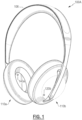
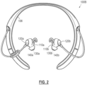
- FIGS. 1 and 2 illustrate two example headsets 100A, 100B.
- Each headset 100 includes a right earpiece 110a and a left earpiece 110b, intercoupled by a supporting structure 106 (e.g., a headband, neckband, etc.) to be worn by a user.
- a supporting structure 106 e.g., a headband, neckband, etc.
- two earpieces 110 may be independent of each other, not intercoupled by a supporting structure.
- Each earpiece 110 may include one or more microphones, such as a feedforward microphone 120 and/or a feedback microphone 140.
- the feedforward microphone 120 may be configured to sense acoustic signals external to the earpiece 110 when properly worn, e.g., to detect acoustic signals in the surrounding environment before they reach the user's ear.
- the feedback microphone 140 may be configured to sense acoustic signals internal to an acoustic volume formed with the user's ear when the earpiece 110 is properly worn, e.g., to detect the acoustic signals reaching the user's ear.
- Each earpiece also includes a driver 130, which is an acoustic transducer for conversion of, e.g., an electrical signal, into an acoustic signal that the user may hear.
- one or more drivers may be included in an earpiece, and an earpiece may in some cases include only a feedforward microphone or only a feedback microphone.
- the visual elements illustrated in the figures may, in some examples, represent an acoustic port wherein acoustic signals enter to ultimately reach such microphones, which may be internal and not physically visible from the exterior.
- one or more of the microphones 120, 140 may be immediately adjacent to the interior of an acoustic port, or may be removed from an acoustic port by a distance, and may include an acoustic waveguide between an acoustic port and an associated microphone.
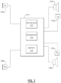
- the processing unit 310 may be physically housed somewhere on or within the headset 100.
- the processing unit 310 may include a processor 312, an audio interface 314, and a battery 316.
- the processing unit 310 may be coupled to one or more feedforward microphone(s) 120, driver(s) 130, and/or feedback microphone(s) 140, in various examples.
- the interface 314 may be a wired or a wireless interface for receiving audio signals, such as a playback audio signal or program content signal, and may include further interface functionality, such as a user interface for receiving user inputs and/or configuration options.
- the battery 316 may be replaceable and/or rechargeable.
- the processing unit 310 may be powered via means other than or in addition to the battery 316, such as by a wired power supply or the like.
- a system may not include an interface 314 to receive a playback signal.
- FIG. 4 illustrates a system and method of processing microphone signals to provide sound to the user's ear, whether for noise reduction or for sound enhancement.
- FIG. 4 presents a simplified schematic diagram to highlight features of such an audio system.
- Various examples of a complete system may include amplifiers, analog-to-digital conversion (ADC), digital-to-analog conversion (DAC), equalization, sub-band separation and synthesis, and other signal processing or the like.
- ADC analog-to-digital conversion
- DAC digital-to-analog conversion
- equalization equalization
- sub-band separation and synthesis and other signal processing or the like.
- a playback signal 410, p(t) may be received to be rendered as an acoustic signal by the driver 130.
- the feedforward microphone 120 provides a feedforward signal 122 that is processed by a feedforward processor 124, having a feedforward transfer function 126, K ff , to produce a feedforward driver component signal 128, which is an anti-noise signal or a combination of the anti-noise signal and an enhanced sound signal.
- the feedback microphone 140 may provide a feedback signal 142 that is processed by a feedback processor 144, having a feedback transfer function 146, K fb , to produce a feedback anti-noise signal 148.
- any of the playback signal 410, the feedforward driver component signal 128, and/or the feedback anti-noise signal 148 may be combined, e.g., by a combiner 420, to generate a driver signal 132, d(t), to be provided to the driver 130.
- any of the playback signal 410, or the feedback anti-noise signal 148 may be omitted and/ or the components necessary to support any of these signals may not be included in a particular implementation of a system.
- a feedforward audio system e.g., a feedforward microphone 120 and a feedforward processor 124, e.g., to provide a feedforward driver component signal 128 for inclusion in a driver signal 132.
- the feedforward microphone 120 may be configured to detect external sound before it reaches an acoustic volume that includes the user's ear. Nonetheless, the feedforward microphone 120 may detect an acoustic signal 136 produced by the driver 130, such that a closed loop exists.
- the feedforward microphone 120 may pick up the acoustic signal 136 when the headset 100 is played at a high volume, when the headset 100 is not being worn (e.g., off-head, reduces physical isolation between the driver 130 and the feedforward microphone 120), or when the feedforward signal 122 is purposefully processed to enhance or improve external sounds rather than reduce them (e.g., amplified to hear through the earpiece), or various other conditions.
- a feedforward signal path may include a feedback loop (e.g., a closed feedforward loop) going, e.g., from the driver signal 132 through the driver 130 producing the acoustic signal 136, which may reach and be picked up by the feedforward microphone 120, and processed through the feedforward transfer function 126, K ff , to be included back into the driver signal 132.
- a feedback loop e.g., a closed feedforward loop
- the feedforward signal 122 may be caused by the acoustic signal 136.
- the feedforward signal 122 may include components related to the driver signal 132. If the closed loop exhibits an instability, such may cause at least one frequency component of the driver signal 132 to progressively increase in amplitude.
- the feedforward system may be described as unstable.
- the electrical and physical system shown in FIG. 4 exhibits a transfer function 134, G, characterizing the transfer of the driver signal 132 through to the feedforward signal 122.
- G the transfer function 134
- the system of the feedforward noise reduction loop is therefore characterized by the combined transfer function GK ff .
- the transfer function 134, G is typically small (e.g., G ⁇ 1), but (as discussed above) various situations may cause the transfer function 134, G, to be larger than typical, and in various situations or user configurations the feedforward transfer function 126, K ff , may be larger than typical (e.g., K ff >> 1) (such as when the headset is used to amplify some external sounds), either of which may yield an instability at one or more frequencies.
- a feedforward instability may be detected by various means.
- a processing system may monitor any of the feedforward signal 122, the feedforward driver component signal 128, the driver signal 132, and/or other signals for a tonal signature.
- an instability may cause one or more tones to rise (in amplitude, in signal energy) above an expected, average, or base level of various components of any of the above-mentioned signals, and the rising tone may be detected by various means.
- a tonal signature may fall in a range of 1 kHz to 8 kHz, or in a range of 3 kHz to 6 kHz, or other ranges, and may depend upon the size and scale of the system (e.g., over-ear headphones versus in-ear earphones). Further details of detecting a tonal signature of instability, such as a rising tone, are included in U.S. Patent No. 9,922,636 titled MITIGATION OF UNSTABLE CONDITIONS IN AN ACTIVE NOISE CONTROL SYSTEM.
- instability detection may use such instability detection, or others, and may further use systems and methods in accord with aspects and examples described herein to confirm that the instability detection is correct and not a false positive (e.g., detecting an instability when an instability does not actually exist).
- aspects and examples described herein adjust the feedforward signal path, e.g., by phase variation, which may confirm the instability detection. For example, if a tonal signature of an instability remains unchanged in spite of an adjusted feedforward signal path, the tonal signature may be due to an external sound and not an instability. If a tonal signature responds to an adjusted feedforward signal path, the tonal signature may be due to an instability, and such may be a basis to confirm the instability detection.
- a system or method of detecting an instability may use one or more of various adjusted phase responses in the signal path (in accord with those described herein), and may require that the detection system or method react to the adjusted phase response (e.g., move closer to or further from stability as a result of the adjusted phase response) to confirm detection, thereby reducing false positives.
- FIG. 5 illustrates an example system 500 that includes a detector 510 to detect signs of feed-forward instability, which may be any of various types of detection, such as detection of a tonal signature as discussed above. If the detector 510 detects an instability, a phase adjuster 520 may adjust a phase response of the feedforward signal path, thus altering the driver component signal 128 in certain examples.
- the phase adjuster 520 may be an all-pass filter (e.g., unity gain at all frequencies of interest) with a phase response that causes various frequencies to emerge from the filter with altered phase.
- the phase adjuster 520 may be a delay block that adds a delay, effectively phase shifting all the frequencies.
- a delay block may provide a delay of tens or hundreds of microseconds, such as 125 ⁇ sec, or 250 psec, for example.
- a 125 psec delay may cause a phase shift of 45° at 1 kHz, a shift of 90° at 2 kHz, and a shift of 180° at 4 kHz, etc.
- the phase adjuster 520 may be incorporated in the feedforward processor 124, e.g., by adding the phase adjuster 520 before or after the feedforward transfer function 126 and/or by altering the feedforward transfer function 126 in response to the detector 510 indicating a detected instability.
- the phase adjuster 520 is applied to confirm an instability detection.
- the detector 510 may monitor for various symptoms (indicators) of instability (e.g., a tonal signature), and when detected, the phase adjuster 520 may be activated to adjust phase response of the feedforward signal path.
- the symptom of instability responds to the adjusted phase response, such as by a tonal signature increasing or decreasing (e.g., in amplitude or frequency), or a rate of change of the tonal signature increases or decreases, such may confirm that an instability exists and is not a false positive.
- a false positive an external sound may trigger the detector 510 to indicate a potential instability, and such may be a false positive, but adjusting the phase response of the feedforward signal path (e.g., by a phase adjuster 520) does not alter the external sound source. Accordingly, the symptom (external sound) detected by the detector 510 remains unchanged in response to the phase adjustment, thus the detector 510 (or other processing) may determine that the detected symptom is a false positive indicator of instability, and that no actual instability exists.
- FIG. 5 and the above description are directed to making phase adjustment in a feedforward signal path to confirm detection of a feedforward instability
- a phase adjustment may equally be placed in a feedback signal path to detect (or confirm) instability of a feedback noise reduction system, in similar fashion.
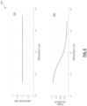
- the phase adjuster 520 may be configured so the phase response 620 shifts the phase of only a range of frequencies, such as a range of frequencies where a tonal signature of an instability may be expected.
- the phase response 620 is only one example of a suitable phase response of a phase adjuster 520.
- the phase adjuster 520 may shift the phase of a range of frequencies by a fixed amount (e.g., the phase response 620 may be a straight horizontal line at a non-zero phase value), or may shift timing of all frequencies by a fixed delay (e.g., the phase response 620 may be a straight inclined line without curvature), or may shift the phase response in various other ways, in some examples, the phase adjuster 520 may be implemented as a modification of the feedforward transfer function 126, which itself has a baseline phase response. Accordingly, the phase adjuster 520 may be implemented as a shift in the baseline phase response of the feedforward transfer function 126. For example, the feedforward transfer function 126 may have a phase response similar to that shown in FIG.
- phase adjustment is applied by shifting phase response of the feedforward transfer function 126, namely by shifting an inflection point in the phase response of the feedforward transfer function 126.
- an indication from the detector 510 may be applied as a command to the feedforward processor 124 to make such a shift or alteration to a phase response of the feedforward transfer function 126.
- various systems and methods in accord with aspects and examples herein may take varying actions in response to the instability, e.g., to mitigate or remove the instability and/or the undesirable consequences of the instability.
- an audio system in accord with those described may alter or replace the feed forward transfer function 126, alter a feedforward controller or feedforward processor 124, change to a less aggressive form of feedforward gain or other processing, alter various parameters of the feedforward system to be less aggressive, alter a driver signal (e.g., mute, reduce, or limit the driver signal 132), provide an indicator to a user (e.g., an audible or visual message, an indicator light, etc.), and/or other actions.
- a driver signal e.g., mute, reduce, or limit the driver signal 132
- an indicator to a user e.g., an audible or visual message, an indicator light, etc.
- Stability criteria for feedforward control may be defined by an engineer at the controller design stage, and various considerations assume a limited range of variation (of system characteristics) over the lifetime of the system. For example, driver output and microphone sensitivity may vary over time and contribute to the electroacoustic transfer function between the driver and the feedforward microphone. Further variability may impact design criteria, such as production variation, headto-head variation, variation in user handling, and environmental factors. Any such variations may cause stability constraints to be violated, and designers must conventionally take a conservative approach to feedforward system design to ensure that instability is avoided. Such an instability may cause the noise reduction system to add undesired signal components rather than reduce them, thus conventional design practices may take highly conservative approaches to avoid an instability occurring, potentially at severe costs to system performance.
- aspects and examples of detecting feedforward instability allow corrective action to be taken to remove the instability when such condition occurs, allowing system designers to design systems that operate under conditions nearer to a boundary of instability, and thus achieve improved performance over a wider feedforward bandwidth.
- aspects and examples herein allow reliable detection if or when the instability boundary is crossed.
- Conventional systems need to be designed to avoid instability, but instability detection in accord with aspects and examples described herein allow the feedforward controller or processor to be designed with relaxed constraints, and resulting improved performance. Accordingly, systems and methods herein may more than double the range of bandwidth in which noise reduction by a feedforward processor may be effective.
- any of the functions of the systems and methods described herein may be implemented or carried out in a digital signal processor (DSP), a microprocessor, a logic controller, logic circuits, and the like, or any combination of these, and may include analog circuit components and/or other components with respect to any particular implementation.
- DSP digital signal processor
- functions and components disclosed herein may operate in the digital domain and certain examples include analog-to-digital (ADC) conversion of analog signals generated by microphones, despite the lack of illustration of ADC's in the various figures.
- ADC functionality may be incorporated in or otherwise internal to a signal processor.
- Any suitable hardware and/or software, including firmware and the like may be configured to carry out or implement components of the aspects and examples disclosed herein, and various implementations of aspects and examples may include components and/or functionality in addition to those disclosed.
Landscapes
- Physics & Mathematics (AREA)
- Engineering & Computer Science (AREA)
- Acoustics & Sound (AREA)
- Multimedia (AREA)
- Signal Processing (AREA)
- Health & Medical Sciences (AREA)
- General Health & Medical Sciences (AREA)
- Neurosurgery (AREA)
- Otolaryngology (AREA)
- Soundproofing, Sound Blocking, And Sound Damping (AREA)
- Headphones And Earphones (AREA)
Description
- Audio headphone, earphone, headset systems, and other personal audio devices are used in various environments for purposes such as entertainment, communications, and professional applications. Many systems incorporate active noise reduction (ANR) features, also known as active noise cancellation (ANC), in which one or more microphones detect sound, such as exterior acoustics captured by a feedforward microphone or interior acoustics captured by a feedback microphone. In some examples, signals from a feedforward microphone may he processed to provide anti-noise signals to be fed to an acoustic transducer (e.g., a speaker, driver) to counteract noise, and may also be processed to enhance sounds, e.g., to improve a user's awareness of his/her surroundings, to improve hearing generally, or to improve sounds that may otherwise be difficult to hear by a user. The feedforward microphone may at times pick up acoustic signals produced by the driver, thereby forming a closed loop system that may become unstable at times.
- Similarly, various audio systems that provide an amplified signal to a speaker, from a microphone, such as public address systems and studio recording or performance venue audio systems, may exhibit instability when the microphone picks up acoustic signals produced by the speaker. While such may generally be referred to as "feedback," and in particular a signature "squeal" from such a condition is often termed "feedback," such is an issue of feedforward instability, caused by an unintended or undesired feedback loop (e.g., signa fed back from the speaker or driver to the microphone).
- In various situations it is therefore desirable to detect when a condition of feedforward instability exists.
-
EP 2106163 A2 (D1) discloses a method for processing signals including an input, an output and a signal processor, comprising detecting a first periodic signal received at an input, adjusting frequency or phase of the first periodic signal in response to detecting the first periodic signal, comparing an amplitude of the first periodic signal before adjusting the frequency or phase to the amplitude after adjusting the frequency or phase to produce a first amplitude change and determining whether the first periodic signal is an acoustic feedback signal based on the first amplitude change. Apparatus including signal processing electronics to receive an input signal from a microphone and programmed to provide phase or frequency changes to signals in a processing channel and to detect periodic feedback signals based on the changes of signals in the processing channel, and a speaker. Variations include feedback reduction or cancellation systems and phase or frequency adjustment systems. -
US 2005/047620 A1 (D2) discloses a hearing aid circuit including a correlation detector that detects correlation at a feedforward path input and that provides a correlation output to a phase shifter. The phase shifter introduces a phase shift along a feedforward path. A phase measurement circuit measures a phase shift at a feedforward path input, and provides a phase measurement output to an internal feedback processor. The internal feedback processor adjusts internal feedback as a function of the phase measurement to suppress coupling of external audio feedback along the feedforward path. -
US 2010/002891 A1 (D5) discloses an acoustic-feedback detection apparatus including: a first level detecting section configured to detect a signal level of sound signals obtained from a position in a sound-signal system in which a microphone and speaker are connected; a first extracting section configured to extract, from the sound signals of which the signal level is detected, signals in a band having a bandwidth predetermined for each of at least one predetermined center frequency; a second level detecting section configured to detect a signal level of the signals in each band, the signals being extracted by the first extracting section; and a determining section configured to determine whether or not acoustic feedback is occurring, on the basis of a threshold determined according to the signal level detected by the first level detecting section and a waveform of each signal level detected by the second level detecting section. - The invention is set out in the claims. Aspects and examples are directed to audio systems and methods that detect instability in a feedforward signal path. The systems and methods operate to detect a possible instability (for example, by detecting a tonal signature) and, when detected, to adjust a phase response of a feedforward signal path (e.g , from a feedforward microphone to a driver signal), e.g., to alter the instability if the instability detection, e.g., the tonal signature, responds to the adjusted phase response, such may indicate or confirm that a feedforward instability exists.
- According to one aspect, an audio device is provided that includes a microphone to provide a first signal, a processor comprising a filter, the processor configured to receive the first signal and provide a second signal, the second signal based at least in part upon processing the first signal using the filter, and an acoustic transducer to convert a third signal, based at least in part upon the second signal, into an acoustic signal, wherein the processor is also configured to detect an indication of instability in any of the first signal, the second signal, or the third signal and to adjust a phase response of the filter in response to detecting the indication of instability.
- The processor is further configured to confirm an instability by monitoring for a change in the indication of instability resulting from adjusting the phase response of the filter. In certain examples, the processor also adjusts one or more parameters involved in providing the second signal in response to confirming the instability, to mitigate an impact of the instability.
- According to various examples, the processor is configured to detect the indication of instability by detecting a tonal signature in any of the first signal, the second signal, or the third signal. The processor may be further configured to determine whether the tonal signature changes in response to adjusting the phase response of the filter and to confirm an instability upon a determination that the tonal signature changed in response to adjusting the phase response of the filter. In certain examples the change in tonal signature is a change in at least one of an amplitude of the tonal signature or a rate of rise or fall of the amplitude of the tonal signature. In various examples, the tonal signature comprises components within a predetermined frequency range. In some examples, the predetermined frequency range is substantially between 1 KHz and 6 KHz. In further examples, the predetermined frequency range may be substantially between 3 KHz and 6 KHz.
- According to another aspect, a method of detecting feedforward instability in an audio device is provided. The method includes monitoring for a potential instability in a feedforward signal path, adjusting a phase response of the feedforward signal path in response to detecting a potential instability in the feedforward signal path, monitoring for a change in the potential instability, the change resulting from the adjusted phase response, and confirming that a feedforward instability exists based upon a detected change in the potential instability.
- Adjusting the phase response comprises shifting an inflection point in the phase response.
- In various examples, monitoring for a potential instability comprises monitoring for a tonal signature. In some examples, monitoring for a change in the potential instability comprises monitoring for a change in at least one of an amplitude of the tonal signature or a rate of rise or fall of the amplitude of the tonal signature. The tonal signature may comprise components within a predetermined frequency range, and in some examples the predetermined frequency range is substantially between 1 KHz and 6 KHz. In further examples, the predetermined frequency range may be substantially between 3 KHz and 6 KHz.
- Certain examples include adjusting one or more parameters of the feedforward signal path in response to confirming that the feedforward instability exists.
- According to another aspect, a headphone system is provided that includes an earpiece having a feedforward microphone configured to detect external acoustic signals and to provide a feedforward signal, a feedforward processor to process the feedforward signal to provide a feedforward driver component signal, an acoustic transducer to produce acoustic signals based upon a driver signal, the driver signal based at least in part upon the feedforward driver component signal, an instability detector configured to monitor for a signal indicative of an unstable closed loop between the acoustic transducer and the feedforward microphone, and a phase adjuster configured to adjust a phase of a transfer function associated with the feedforward processor in response to detecting the signal indicative of an unstable closed loop between the acoustic transducer and the feedforward microphone.
- In some examples the feedforward processor is configured to apply the transfer function to the feedforward signal.
- According to various examples, the instability detector is configured to monitor for a tonal signature indicative of an unstable closed loop between the acoustic transducer and the feedforward microphone. In certain examples, the instability detector may be further configured to monitor for a change in the tonal signature in response to the adjusted phase of the transfer function and to confirm the unstable closed loop based upon a determination that the tonal signature changed in response to the adjusted phase. In some examples, the change in the tonal signature is a change in at least one of an amplitude of the tonal signature or a rate of rise or fall of the amplitude of the tonal signature.
- In certain examples, the feedforward processor is further configured to adjust a parameter of the feedforward processing to mitigate the unstable closed loop in response to a confirmation of the unstable closed loop.
- Still other aspects, examples, and advantages of these exemplary aspects and examples are discussed in detail below. Examples disclosed herein may be combined with other examples in any manner consistent with at least one of the principles disclosed herein, and references to "an example," "some examples," "an alternate example," "various examples," "one example" or the like are not necessarily mutually exclusive and are intended to indicate that a particular feature, structure, or characteristic described may be included in at least one example. The appearances of such terms herein are not necessarily all referring to the same example.
- Various aspects of at least one example are discussed below with reference to the accompanying figures, which are not intended to be drawn to scale. The figures are included to provide illustration and a further understanding of the various aspects and examples, and are incorporated in and constitute a part of this specification, but are not intended as a definition of the limits of the invention. In the figures, identical or nearly identical components illustrated in various figures may be represented by identical or similar numerals. For purposes of clarity, not every component may be labeled in every figure. In the figures:
-
FIG. 1 is a perspective view of one example headset form factor; -
FIG. 2 is a perspective view of another example headset form factor; -
FIG. 3 is a schematic block diagram of example audio processing that may be incorporated into various audio systems; -
FIG. 4 is a schematic diagram of an example audio system incorporating feedforward and feedback components; -
FIG. 5 is a schematic diagram of an example system for instability detection and confirmation; and -
FIG. 6 is a schematic diagram of an example filter response for phase adjustment. - Aspects of the present disclosure are directed to audio systems that include feedforward signal processing, such as sound enhancing and/or noise cancelling headphones or headsets, and methods that detect instability in the feedforward system. Noise cancelling systems operate to reduce acoustic noise components heard by a user, e.g., wearer, of the headset. Noise cancelling systems may include feedforward and/or feedback characteristics. A feedforward component detects noise external to the headset (e.g., via an external microphone) and acts to provide an anti-noise signal to counter the external noise expected to be transferred through to the user's ear. A feedback component detects acoustic signals reaching the user's ear (e.g., via an internal microphone) and processes the detected signals to counteract any signal components not intended to be part of the user's acoustic experience. Examples disclosed herein may be coupled to, or placed in connection with, other systems, through wired or wireless means, or may be independent of any other systems or equipment.
- The systems and methods disclosed herein may include or operate in, in some examples, an aviation headset, a telephone headset, media headphones, network gaming headphones, hearing assistance headphones, hearing aids, or any combination of these or others. Throughout this disclosure the terms "headset," "headphone," "earphone," and "headphone set" are used interchangeably, and no distinction is meant to be made by the use of one term over another unless the context clearly indicates otherwise. Additionally, aspects and examples in accord with those disclosed herein are applicable to various form factors, such as in-ear transducers or earbuds and on-ear or over-ear headphones, and others. Any suitable form factor is therefore contemplated by the terms "headset," "headphone," and "headphone set" as used herein.
- Examples disclosed may be combined with other examples in any manner consistent with at least one of the principles disclosed herein, and references to "an example," "some examples," "an alternate example," "various examples," "one example" or the like are not necessarily mutually exclusive and are intended to indicate that a particular feature, structure, or characteristic described may be included in at least one example. The appearances of such terms herein are not necessarily all referring to the same example.
- It is to be appreciated that examples of the methods and apparatuses discussed herein are not limited in application to the details of construction and the arrangement of components set forth in the following description or illustrated in the accompanying drawings. The methods and apparatuses are capable of implementation in other examples and of being practiced or of being carried out in various ways. Examples of specific implementations are provided herein for illustrative purposes only and are not intended to be limiting. Also, the phraseology and terminology used herein is for the purpose of description and should not be regarded as limiting. The use herein of "including," "comprising," "having," "containing," "involving," and variations thereof is meant to encompass the items listed thereafter and equivalents thereof as well as additional items. References to "or" may be construed as inclusive so that any terms described using "or" may indicate any of a single, more than one, and all of the described terms. Any references to front and back, left and right, top and bottom, upper and lower, and vertical and horizontal are intended for convenience of description, not to limit the present systems and methods or their components to any one positional or spatial orientation.
- For various components described herein, a designation of "a" or "b" in the reference numeral may be used to indicate "right" or "left" versions of one or more components. When no such designation is included, the description is without regard to the right or left and is equally applicable to either of the right or left, which is generally the case for the various examples described herein. Additionally, aspects and examples described herein are equally applicable to monaural or single-sided personal acoustic devices and do not necessarily require both of a right and left side.
-
FIGS. 1 and2 illustrate twoexample headsets right earpiece 110a and aleft earpiece 110b, intercoupled by a supporting structure 106 (e.g., a headband, neckband, etc.) to be worn by a user. In some examples, two earpieces 110 may be independent of each other, not intercoupled by a supporting structure. Each earpiece 110 may include one or more microphones, such as afeedforward microphone 120 and/or afeedback microphone 140. Thefeedforward microphone 120 may be configured to sense acoustic signals external to the earpiece 110 when properly worn, e.g., to detect acoustic signals in the surrounding environment before they reach the user's ear. Thefeedback microphone 140 may be configured to sense acoustic signals internal to an acoustic volume formed with the user's ear when the earpiece 110 is properly worn, e.g., to detect the acoustic signals reaching the user's ear. Each earpiece also includes adriver 130, which is an acoustic transducer for conversion of, e.g., an electrical signal, into an acoustic signal that the user may hear. In various examples, one or more drivers may be included in an earpiece, and an earpiece may in some cases include only a feedforward microphone or only a feedback microphone. - While the
reference numerals microphones - Shown in
FIG. 3 is an example of aprocessing unit 310 that may be physically housed somewhere on or within the headset 100. Theprocessing unit 310 may include aprocessor 312, anaudio interface 314, and abattery 316. Theprocessing unit 310 may be coupled to one or more feedforward microphone(s) 120, driver(s) 130, and/or feedback microphone(s) 140, in various examples. In various examples, theinterface 314 may be a wired or a wireless interface for receiving audio signals, such as a playback audio signal or program content signal, and may include further interface functionality, such as a user interface for receiving user inputs and/or configuration options. In various examples, thebattery 316 may be replaceable and/or rechargeable. In various examples, theprocessing unit 310 may be powered via means other than or in addition to thebattery 316, such as by a wired power supply or the like. In some examples, a system may not include aninterface 314 to receive a playback signal. -
FIG. 4 illustrates a system and method of processing microphone signals to provide sound to the user's ear, whether for noise reduction or for sound enhancement.FIG. 4 presents a simplified schematic diagram to highlight features of such an audio system. Various examples of a complete system may include amplifiers, analog-to-digital conversion (ADC), digital-to-analog conversion (DAC), equalization, sub-band separation and synthesis, and other signal processing or the like. In some examples, aplayback signal 410, p(t), may be received to be rendered as an acoustic signal by thedriver 130. Thefeedforward microphone 120 provides afeedforward signal 122 that is processed by afeedforward processor 124, having afeedforward transfer function 126, Kff, to produce a feedforwarddriver component signal 128, which is an anti-noise signal or a combination of the anti-noise signal and an enhanced sound signal. . Thefeedback microphone 140 may provide afeedback signal 142 that is processed by afeedback processor 144, having afeedback transfer function 146, Kfb, to produce a feedbackanti-noise signal 148. In various examples, any of theplayback signal 410, the feedforwarddriver component signal 128, and/or the feedbackanti-noise signal 148 may be combined, e.g., by acombiner 420, to generate adriver signal 132, d(t), to be provided to thedriver 130. In various examples, any of theplayback signal 410, or the feedbackanti-noise signal 148 may be omitted and/ or the components necessary to support any of these signals may not be included in a particular implementation of a system. - Various examples described herein include a feedforward audio system, e.g., a
feedforward microphone 120 and afeedforward processor 124, e.g., to provide a feedforwarddriver component signal 128 for inclusion in adriver signal 132. Thefeedforward microphone 120 may be configured to detect external sound before it reaches an acoustic volume that includes the user's ear. Nonetheless, thefeedforward microphone 120 may detect anacoustic signal 136 produced by thedriver 130, such that a closed loop exists. For example, thefeedforward microphone 120 may pick up theacoustic signal 136 when the headset 100 is played at a high volume, when the headset 100 is not being worn (e.g., off-head, reduces physical isolation between thedriver 130 and the feedforward microphone 120), or when thefeedforward signal 122 is purposefully processed to enhance or improve external sounds rather than reduce them (e.g., amplified to hear through the earpiece), or various other conditions. - Accordingly, in various examples and/or at various times, a feedforward signal path may include a feedback loop (e.g., a closed feedforward loop) going, e.g., from the
driver signal 132 through thedriver 130 producing theacoustic signal 136, which may reach and be picked up by thefeedforward microphone 120, and processed through thefeedforward transfer function 126, Kff, to be included back into thedriver signal 132. Accordingly, at least some components of thefeedforward signal 122 may be caused by theacoustic signal 136. Alternately stated, thefeedforward signal 122 may include components related to thedriver signal 132. If the closed loop exhibits an instability, such may cause at least one frequency component of thedriver signal 132 to progressively increase in amplitude. This may be perceived by the user as an audible artifact, such as a tone or squealing, and may reach a limit at a maximum amplitude thedriver 130 is capable of producing, which may be extremely loud. Accordingly, when such a condition exists, the feedforward system may be described as unstable. - The electrical and physical system shown in
FIG. 4 exhibits atransfer function 134, G, characterizing the transfer of thedriver signal 132 through to thefeedforward signal 122. In other words, the response of thefeedforward signal 122 to thedriver signal 132 is characterized by thetransfer function 134, G. The system of the feedforward noise reduction loop is therefore characterized by the combined transfer function GKff. The feedforward noise reduction system may be unstable if GKff = 1 for one or more frequencies. In various examples, thetransfer function 134, G, is typically small (e.g., G << 1), but (as discussed above) various situations may cause thetransfer function 134, G, to be larger than typical, and in various situations or user configurations thefeedforward transfer function 126, Kff, may be larger than typical (e.g., Kff >> 1) (such as when the headset is used to amplify some external sounds), either of which may yield an instability at one or more frequencies. - In various examples, a feedforward instability may be detected by various means. In at least one example, a processing system may monitor any of the
feedforward signal 122, the feedforwarddriver component signal 128, thedriver signal 132, and/or other signals for a tonal signature. For example, an instability may cause one or more tones to rise (in amplitude, in signal energy) above an expected, average, or base level of various components of any of the above-mentioned signals, and the rising tone may be detected by various means. In various examples, a tonal signature may fall in a range of 1 kHz to 8 kHz, or in a range of 3 kHz to 6 kHz, or other ranges, and may depend upon the size and scale of the system (e.g., over-ear headphones versus in-ear earphones). Further details of detecting a tonal signature of instability, such as a rising tone, are included inU.S. Patent No. 9,922,636 - Various examples may use such instability detection, or others, and may further use systems and methods in accord with aspects and examples described herein to confirm that the instability detection is correct and not a false positive (e.g., detecting an instability when an instability does not actually exist).
- Aspects and examples described herein adjust the feedforward signal path, e.g., by phase variation, which may confirm the instability detection. For example, if a tonal signature of an instability remains unchanged in spite of an adjusted feedforward signal path, the tonal signature may be due to an external sound and not an instability. If a tonal signature responds to an adjusted feedforward signal path, the tonal signature may be due to an instability, and such may be a basis to confirm the instability detection. Accordingly, in various examples, a system or method of detecting an instability may use one or more of various adjusted phase responses in the signal path (in accord with those described herein), and may require that the detection system or method react to the adjusted phase response (e.g., move closer to or further from stability as a result of the adjusted phase response) to confirm detection, thereby reducing false positives.
-
FIG. 5 illustrates anexample system 500 that includes adetector 510 to detect signs of feed-forward instability, which may be any of various types of detection, such as detection of a tonal signature as discussed above. If thedetector 510 detects an instability, aphase adjuster 520 may adjust a phase response of the feedforward signal path, thus altering thedriver component signal 128 in certain examples. In various examples, thephase adjuster 520 may be an all-pass filter (e.g., unity gain at all frequencies of interest) with a phase response that causes various frequencies to emerge from the filter with altered phase. In other examples, thephase adjuster 520 may be a delay block that adds a delay, effectively phase shifting all the frequencies. For example, a delay block may provide a delay of tens or hundreds of microseconds, such as 125 µsec, or 250 psec, for example. For example, a 125 psec delay may cause a phase shift of 45° at 1 kHz, a shift of 90° at 2 kHz, and a shift of 180° at 4 kHz, etc. In yet other examples, thephase adjuster 520 may be incorporated in thefeedforward processor 124, e.g., by adding thephase adjuster 520 before or after thefeedforward transfer function 126 and/or by altering thefeedforward transfer function 126 in response to thedetector 510 indicating a detected instability. In various examples, a phase shift (e.g., by a phase adjuster 520)=may be provided at any of various positions of the feedforward signal path, such as after= thecombiner 420, e.g., acting on thedriver signal 132, for instance. - Adjusting a phase response of the feedforward signal path (e.g., by a phase adjuster 520)=may alter or change an instability in the feedforward signal path, and thereby alter a= detected indication of instability. Accordingly, the
phase adjuster 520 is applied to confirm an instability detection. For example, thedetector 510 may monitor for various symptoms (indicators) of instability (e.g., a tonal signature), and when detected, thephase adjuster 520 may be activated to adjust phase response of the feedforward signal path. If the symptom of instability responds to the adjusted phase response, such as by a tonal signature increasing or decreasing (e.g., in amplitude or frequency), or a rate of change of the tonal signature increases or decreases, such may confirm that an instability exists and is not a false positive. In an example case of a false positive, an external sound may trigger thedetector 510 to indicate a potential instability, and such may be a false positive, but adjusting the phase response of the feedforward signal path (e.g., by a phase adjuster 520) does not alter the external sound source. Accordingly, the symptom (external sound) detected by thedetector 510 remains unchanged in response to the phase adjustment, thus the detector 510 (or other processing) may determine that the detected symptom is a false positive indicator of instability, and that no actual instability exists. - While
FIG. 5 and the above description are directed to making phase adjustment in a feedforward signal path to confirm detection of a feedforward instability, a phase adjustment may equally be placed in a feedback signal path to detect (or confirm) instability of a feedback noise reduction system, in similar fashion. -
FIG. 6 illustrates an example response 600 (e.g., transfer function) of a phase adjuster 520.=Themagnitude response 610 is unity (Gain = l.Ox, 0 dB) and thephase response 620= adjusts a range of frequencies through various phase shifts. In some examples, thephase adjuster 520 may be configured so thephase response 620 shifts the phase of only a range of frequencies, such as a range of frequencies where a tonal signature of an instability may be expected. Thephase response 620 is only one example of a suitable phase response of aphase adjuster 520. In various examples, thephase adjuster 520 may shift the phase of a range of frequencies by a fixed amount (e.g., thephase response 620 may be a straight horizontal line at a non-zero phase value), or may shift timing of all frequencies by a fixed delay (e.g., thephase response 620 may be a straight inclined line without curvature), or may shift the phase response in various other ways, in some examples, thephase adjuster 520 may be implemented as a modification of thefeedforward transfer function 126, which itself has a baseline phase response. Accordingly, thephase adjuster 520 may be implemented as a shift in the baseline phase response of thefeedforward transfer function 126. For example, thefeedforward transfer function 126 may have a phase response similar to that shown inFIG. 6 (for illustrative purposes) and a phase adjustment is applied by shifting phase response of thefeedforward transfer function 126, namely by shifting an inflection point in the phase response of thefeedforward transfer function 126. In some examples, an indication from thedetector 510 may be applied as a command to thefeedforward processor 124 to make such a shift or alteration to a phase response of thefeedforward transfer function 126. - When the
detector 510 indicates that a potential feedforward instability is detected, and is confirmed by response to thephase adjuster 520, various systems and methods in accord with aspects and examples herein may take varying actions in response to the instability, e.g., to mitigate or remove the instability and/or the undesirable consequences of the instability. For example, an audio system in accord with those described may alter or replace the feedforward transfer function 126, alter a feedforward controller orfeedforward processor 124, change to a less aggressive form of feedforward gain or other processing, alter various parameters of the feedforward system to be less aggressive, alter a driver signal (e.g., mute, reduce, or limit the driver signal 132), provide an indicator to a user (e.g., an audible or visual message, an indicator light, etc.), and/or other actions. - The above described aspects and examples provide numerous potential benefits to a personal audio device that includes feedforward noise reduction. Stability criteria for feedforward control may be defined by an engineer at the controller design stage, and various considerations assume a limited range of variation (of system characteristics) over the lifetime of the system. For example, driver output and microphone sensitivity may vary over time and contribute to the electroacoustic transfer function between the driver and the feedforward microphone. Further variability may impact design criteria, such as production variation, headto-head variation, variation in user handling, and environmental factors. Any such variations may cause stability constraints to be violated, and designers must conventionally take a conservative approach to feedforward system design to ensure that instability is avoided. Such an instability may cause the noise reduction system to add undesired signal components rather than reduce them, thus conventional design practices may take highly conservative approaches to avoid an instability occurring, potentially at severe costs to system performance.
- However, aspects and examples of detecting feedforward instability, as described herein, allow corrective action to be taken to remove the instability when such condition occurs, allowing system designers to design systems that operate under conditions nearer to a boundary of instability, and thus achieve improved performance over a wider feedforward bandwidth. Aspects and examples herein allow reliable detection if or when the instability boundary is crossed. Conventional systems need to be designed to avoid instability, but instability detection in accord with aspects and examples described herein allow the feedforward controller or processor to be designed with relaxed constraints, and resulting improved performance. Accordingly, systems and methods herein may more than double the range of bandwidth in which noise reduction by a feedforward processor may be effective.
- In various examples, any of the functions of the systems and methods described herein may be implemented or carried out in a digital signal processor (DSP), a microprocessor, a logic controller, logic circuits, and the like, or any combination of these, and may include analog circuit components and/or other components with respect to any particular implementation. Functions and components disclosed herein may operate in the digital domain and certain examples include analog-to-digital (ADC) conversion of analog signals generated by microphones, despite the lack of illustration of ADC's in the various figures. Such ADC functionality may be incorporated in or otherwise internal to a signal processor. Any suitable hardware and/or software, including firmware and the like, may be configured to carry out or implement components of the aspects and examples disclosed herein, and various implementations of aspects and examples may include components and/or functionality in addition to those disclosed.
Claims (10)
- An audio device (100A, 100B) comprising:a microphone (120) to provide a first signal (122);a processor comprising a filter, the processor configured to receive the first signal (122) and provide a second signal (128), the second signal being an anti-noise signal, the second signal (128) based at least in part upon processing the first signal (122) using the filter; andan acoustic transducer (130) to convert a third signal (132), based at least in part upon the second signal (128), into an acoustic signal (136);wherein the processor is also configured to detect an indication of instability in any of the first signal (122), the second signal (128), or the third signal (132) and to adjust a phase response (620) of the filter in response to detecting the indication of instability;characterized in that the processor is further configured to confirm an instability by monitoring for a change in the indication of instability resulting from adjusting the phase response of the filter;wherein adjusting the phase response (620) comprises shifting an inflection point in the phase response (620) of the filter.
- The audio device (100A, 100B) of claim 1 wherein the processor is further configured to adjust one or more parameters involved in providing the second signal (128) in response to confirming the instability, to mitigate an impact of the instability.
- The audio device (100A, 100B) of claim 1 wherein the processor is configured to detect the indication of instability by detecting a tonal signature in any of the first signal (122), the second signal (128), or the third signal (132).
- The audio device (100A, 100B) of claim 3 wherein the processor is further configured to determine whether the tonal signature changes in response to adjusting the phase response of the filter and to confirm an instability upon a determination that the tonal signature changed in response to adjusting the phase response of the filter.
- The audio device of claim 4 wherein the change in tonal signature is a change in at least one of an amplitude of the tonal signature or a rate of rise or fall of the amplitude of the tonal signature.
- The audio device (100A, 100B) of claim 3 wherein the tonal signature comprises components within a predetermined frequency range.
- A method of detecting feedforward instability in an audio device (100A, 100B), the method
comprising:monitoring for a potential instability in a feedforward signal path comprising an anti-noise signal (128);adjusting a phase response of the feedforward signal path in response to detecting a potential instability in the feedforward signal path;characterized in that the method comprises:monitoring for a change in the potential instability, the change resulting from the adjusted phase response; andconfirming that a feedforward instability exists based upon a detected change in the potential instability;wherein adjusting the phase response comprises shifting an inflection point in the phase response. - The method of claim 7 wherein monitoring for a potential instability comprises monitoring for a tonal signature.
- The method of claim 7 further comprising adjusting one or more parameters of the feedforward signal path in response to confirming that the feedforward instability exists.
- A headphone system (100A, 100B) comprising;the audio device (100A, 100B) of one of the claims 1 to 6; andan earpiece, wherein the microphone (120, 120a, 120b) and the acoustic transducer (130) are included in the earpiece, and wherein the microphone (120, 120a, 120b) is configured to detect external acoustic signals.
Applications Claiming Priority (2)
| Application Number | Priority Date | Filing Date | Title |
|---|---|---|---|
| US15/983,313 US10885896B2 (en) | 2018-05-18 | 2018-05-18 | Real-time detection of feedforward instability |
| PCT/US2019/032425 WO2019222355A1 (en) | 2018-05-18 | 2019-05-15 | Real-time detection of feedforward instability |
Publications (2)
| Publication Number | Publication Date |
|---|---|
| EP3794585A1 EP3794585A1 (en) | 2021-03-24 |
| EP3794585B1 true EP3794585B1 (en) | 2025-07-02 |
Family
ID=66669145
Family Applications (1)
| Application Number | Title | Priority Date | Filing Date |
|---|---|---|---|
| EP19727263.6A Active EP3794585B1 (en) | 2018-05-18 | 2019-05-15 | Real-time detection of feedforward instability |
Country Status (4)
| Country | Link |
|---|---|
| US (1) | US10885896B2 (en) |
| EP (1) | EP3794585B1 (en) |
| CN (1) | CN112236814B (en) |
| WO (1) | WO2019222355A1 (en) |
Families Citing this family (1)
| Publication number | Priority date | Publication date | Assignee | Title |
|---|---|---|---|---|
| CN111988690B (en) * | 2019-05-23 | 2023-06-27 | 小鸟创新(北京)科技有限公司 | Earphone wearing state detection method and device and earphone |
Citations (22)
| Publication number | Priority date | Publication date | Assignee | Title |
|---|---|---|---|---|
| DE19748079A1 (en) | 1997-10-30 | 1999-05-06 | Siemens Audiologische Technik | Hearing aid with feedback suppression |
| WO2004105430A1 (en) | 2003-05-26 | 2004-12-02 | Dynamic Hearing Pty Ltd | Oscillation suppression |
| US20050047620A1 (en) | 2003-09-03 | 2005-03-03 | Resistance Technology, Inc. | Hearing aid circuit reducing feedback |
| US20060093173A1 (en) | 2004-10-14 | 2006-05-04 | Volkmar Hamacher | Method and signal processor for reducing feedback in an audio system |
| EP2106163A2 (en) | 2008-03-25 | 2009-09-30 | Starkey Laboratories, Inc. | Apparatus and method for dynamic detection and attenuation of periodic acoustic feedback |
| US20100002891A1 (en) * | 2008-07-01 | 2010-01-07 | Sony Corporation | Apparatus and method for detecting acoustic feedback |
| US20110243343A1 (en) | 2010-03-30 | 2011-10-06 | Gauger Jr Daniel M | Frequency-dependent anr reference sound compression |
| US8355517B1 (en) | 2009-09-30 | 2013-01-15 | Intricon Corporation | Hearing aid circuit with feedback transition adjustment |
| WO2013052327A2 (en) | 2011-10-03 | 2013-04-11 | Bose Corporation | Instability detection and avoidance in a feedback system |
| US8477952B2 (en) | 2005-04-27 | 2013-07-02 | Oticon A/S | Audio system with feedback detection means |
| WO2013151918A1 (en) | 2012-04-02 | 2013-10-10 | Bose Corporation | Instability detection and avoidance in a feedback system |
| US20140126733A1 (en) | 2012-11-02 | 2014-05-08 | Daniel M. Gauger, Jr. | User Interface for ANR Headphones with Active Hear-Through |
| WO2014070992A1 (en) | 2012-11-02 | 2014-05-08 | Bose Corporation | Reducing occlusion effect in anr headphones |
| WO2014070995A1 (en) | 2012-11-02 | 2014-05-08 | Bose Corporation | Providing audio and ambient sound simultaneously in anr headphones |
| WO2014071013A1 (en) | 2012-11-02 | 2014-05-08 | Bose Corporation | Binaural telepresence |
| US8942298B2 (en) | 2005-12-09 | 2015-01-27 | Sonitor Technologies As | Data communications |
| US20160078855A1 (en) | 2012-10-12 | 2016-03-17 | Cirrus Logic International Semiconductor Ltd. | Noise cancellation |
| US9392379B2 (en) | 2006-03-13 | 2016-07-12 | Starkey Laboratories, Inc. | Output phase modulation entrainment containment for digital filters |
| JP5982728B2 (en) | 2015-10-28 | 2016-08-31 | パイオニア株式会社 | Active noise control device and active noise control method |
| US20170053638A1 (en) | 2015-08-21 | 2017-02-23 | Cirrus Logic International Semiconductor Ltd. | Hybrid adaptive noise cancellation system with filtered error microphone signal |
| US20170365245A1 (en) | 2016-06-20 | 2017-12-21 | Bose Corporation | Mitigation of unstable conditions in an active noise control system |
| EP3288285A1 (en) | 2016-08-26 | 2018-02-28 | Starkey Laboratories, Inc. | Method and apparatus for robust acoustic feedback cancellation |
Family Cites Families (16)
| Publication number | Priority date | Publication date | Assignee | Title |
|---|---|---|---|---|
| CA2003755C (en) * | 1989-11-23 | 2000-02-15 | Gary Rogalski | Audio signal expander apparatus |
| AU7355594A (en) | 1993-06-23 | 1995-01-17 | Noise Cancellation Technologies, Inc. | Variable gain active noise cancellation system with improved residual noise sensing |
| EP0814456A3 (en) | 1996-06-17 | 1998-10-07 | Lord Corporation | Active noise or vibration control (ANVC) system and method including enhanced reference signals |
| JP2002285958A (en) * | 2001-03-28 | 2002-10-03 | Matsushita Refrig Co Ltd | Control device for linear compressor |
| US8498407B2 (en) | 2008-12-02 | 2013-07-30 | Qualcomm Incorporated | Systems and methods for double-talk detection in acoustically harsh environments |
| US8155334B2 (en) | 2009-04-28 | 2012-04-10 | Bose Corporation | Feedforward-based ANR talk-through |
| US8611553B2 (en) * | 2010-03-30 | 2013-12-17 | Bose Corporation | ANR instability detection |
| CN102422346B (en) | 2009-05-11 | 2014-09-10 | 皇家飞利浦电子股份有限公司 | Audio Noise Cancellation |
| US8385559B2 (en) * | 2009-12-30 | 2013-02-26 | Robert Bosch Gmbh | Adaptive digital noise canceller |
| US8630437B2 (en) * | 2010-02-23 | 2014-01-14 | University Of Utah Research Foundation | Offending frequency suppression in hearing aids |
| CN102300140B (en) * | 2011-08-10 | 2013-12-18 | 歌尔声学股份有限公司 | Speech enhancing method and device of communication earphone and noise reduction communication earphone |
| US8798283B2 (en) | 2012-11-02 | 2014-08-05 | Bose Corporation | Providing ambient naturalness in ANR headphones |
| US9654874B2 (en) * | 2013-12-16 | 2017-05-16 | Qualcomm Incorporated | Systems and methods for feedback detection |
| US9466282B2 (en) | 2014-10-31 | 2016-10-11 | Qualcomm Incorporated | Variable rate adaptive active noise cancellation |
| US9728179B2 (en) | 2015-10-16 | 2017-08-08 | Avnera Corporation | Calibration and stabilization of an active noise cancelation system |
| US9894452B1 (en) * | 2017-02-24 | 2018-02-13 | Bose Corporation | Off-head detection of in-ear headset |
-
2018
- 2018-05-18 US US15/983,313 patent/US10885896B2/en active Active
-
2019
- 2019-05-15 WO PCT/US2019/032425 patent/WO2019222355A1/en not_active Ceased
- 2019-05-15 EP EP19727263.6A patent/EP3794585B1/en active Active
- 2019-05-15 CN CN201980037351.0A patent/CN112236814B/en active Active
Patent Citations (22)
| Publication number | Priority date | Publication date | Assignee | Title |
|---|---|---|---|---|
| DE19748079A1 (en) | 1997-10-30 | 1999-05-06 | Siemens Audiologische Technik | Hearing aid with feedback suppression |
| WO2004105430A1 (en) | 2003-05-26 | 2004-12-02 | Dynamic Hearing Pty Ltd | Oscillation suppression |
| US20050047620A1 (en) | 2003-09-03 | 2005-03-03 | Resistance Technology, Inc. | Hearing aid circuit reducing feedback |
| US20060093173A1 (en) | 2004-10-14 | 2006-05-04 | Volkmar Hamacher | Method and signal processor for reducing feedback in an audio system |
| US8477952B2 (en) | 2005-04-27 | 2013-07-02 | Oticon A/S | Audio system with feedback detection means |
| US8942298B2 (en) | 2005-12-09 | 2015-01-27 | Sonitor Technologies As | Data communications |
| US9392379B2 (en) | 2006-03-13 | 2016-07-12 | Starkey Laboratories, Inc. | Output phase modulation entrainment containment for digital filters |
| EP2106163A2 (en) | 2008-03-25 | 2009-09-30 | Starkey Laboratories, Inc. | Apparatus and method for dynamic detection and attenuation of periodic acoustic feedback |
| US20100002891A1 (en) * | 2008-07-01 | 2010-01-07 | Sony Corporation | Apparatus and method for detecting acoustic feedback |
| US8355517B1 (en) | 2009-09-30 | 2013-01-15 | Intricon Corporation | Hearing aid circuit with feedback transition adjustment |
| US20110243343A1 (en) | 2010-03-30 | 2011-10-06 | Gauger Jr Daniel M | Frequency-dependent anr reference sound compression |
| WO2013052327A2 (en) | 2011-10-03 | 2013-04-11 | Bose Corporation | Instability detection and avoidance in a feedback system |
| WO2013151918A1 (en) | 2012-04-02 | 2013-10-10 | Bose Corporation | Instability detection and avoidance in a feedback system |
| US20160078855A1 (en) | 2012-10-12 | 2016-03-17 | Cirrus Logic International Semiconductor Ltd. | Noise cancellation |
| WO2014070992A1 (en) | 2012-11-02 | 2014-05-08 | Bose Corporation | Reducing occlusion effect in anr headphones |
| WO2014071013A1 (en) | 2012-11-02 | 2014-05-08 | Bose Corporation | Binaural telepresence |
| WO2014070995A1 (en) | 2012-11-02 | 2014-05-08 | Bose Corporation | Providing audio and ambient sound simultaneously in anr headphones |
| US20140126733A1 (en) | 2012-11-02 | 2014-05-08 | Daniel M. Gauger, Jr. | User Interface for ANR Headphones with Active Hear-Through |
| US20170053638A1 (en) | 2015-08-21 | 2017-02-23 | Cirrus Logic International Semiconductor Ltd. | Hybrid adaptive noise cancellation system with filtered error microphone signal |
| JP5982728B2 (en) | 2015-10-28 | 2016-08-31 | パイオニア株式会社 | Active noise control device and active noise control method |
| US20170365245A1 (en) | 2016-06-20 | 2017-12-21 | Bose Corporation | Mitigation of unstable conditions in an active noise control system |
| EP3288285A1 (en) | 2016-08-26 | 2018-02-28 | Starkey Laboratories, Inc. | Method and apparatus for robust acoustic feedback cancellation |
Also Published As
| Publication number | Publication date |
|---|---|
| US10885896B2 (en) | 2021-01-05 |
| US20190355342A1 (en) | 2019-11-21 |
| EP3794585A1 (en) | 2021-03-24 |
| CN112236814A (en) | 2021-01-15 |
| WO2019222355A1 (en) | 2019-11-21 |
| CN112236814B (en) | 2024-12-17 |
Similar Documents
| Publication | Publication Date | Title |
|---|---|---|
| EP3803851B1 (en) | Real-time detection of feedback instability | |
| JP7098771B2 (en) | Audio signal processing for noise reduction | |
| JP6965216B2 (en) | Providing the naturalness of the surroundings with ANR headphones | |
| CN110089129B (en) | On-head/off-head detection of personal sound devices using handset microphones | |
| CN106937196B (en) | Hearing headset | |
| JP5610945B2 (en) | Noise canceling headphones and noise canceling earmuffs | |
| JP6055108B2 (en) | Binaural telepresence | |
| US12249312B2 (en) | Synchronization of instability mitigation in audio devices | |
| CN113728378A (en) | Wind noise suppression and method for active noise cancellation systems | |
| JP2015204627A (en) | Anc active noise control audio headset reducing electrical hiss | |
| EP3977443B1 (en) | Multipurpose microphone in acoustic devices | |
| CN113994711A (en) | Dynamic control of multiple feedforward microphones in an active noise reduction device | |
| CN102780957B (en) | Acoustic equipment and the method for detection abnormal sound | |
| CN117295000A (en) | Hearing aids that include active obstruction cancellation systems | |
| EP3544313B1 (en) | Sound output device and control method for sound output device | |
| US10885896B2 (en) | Real-time detection of feedforward instability | |
| US20260038476A1 (en) | Real-time detection of feedback instability | |
| US11849284B2 (en) | Feedback control using a correlation measure | |
| CN116584107A (en) | Headphones with noise cancellation enabled | |
| CN117278900A (en) | A method of howling suppression for headphone monitoring |
Legal Events
| Date | Code | Title | Description |
|---|---|---|---|
| STAA | Information on the status of an ep patent application or granted ep patent |
Free format text: STATUS: UNKNOWN |
|
| STAA | Information on the status of an ep patent application or granted ep patent |
Free format text: STATUS: THE INTERNATIONAL PUBLICATION HAS BEEN MADE |
|
| PUAI | Public reference made under article 153(3) epc to a published international application that has entered the european phase |
Free format text: ORIGINAL CODE: 0009012 |
|
| STAA | Information on the status of an ep patent application or granted ep patent |
Free format text: STATUS: REQUEST FOR EXAMINATION WAS MADE |
|
| 17P | Request for examination filed |
Effective date: 20201209 |
|
| AK | Designated contracting states |
Kind code of ref document: A1 Designated state(s): AL AT BE BG CH CY CZ DE DK EE ES FI FR GB GR HR HU IE IS IT LI LT LU LV MC MK MT NL NO PL PT RO RS SE SI SK SM TR |
|
| AX | Request for extension of the european patent |
Extension state: BA ME |
|
| DAV | Request for validation of the european patent (deleted) | ||
| DAX | Request for extension of the european patent (deleted) | ||
| STAA | Information on the status of an ep patent application or granted ep patent |
Free format text: STATUS: EXAMINATION IS IN PROGRESS |
|
| 17Q | First examination report despatched |
Effective date: 20230123 |
|
| GRAP | Despatch of communication of intention to grant a patent |
Free format text: ORIGINAL CODE: EPIDOSNIGR1 |
|
| STAA | Information on the status of an ep patent application or granted ep patent |
Free format text: STATUS: GRANT OF PATENT IS INTENDED |
|
| INTG | Intention to grant announced |
Effective date: 20250403 |
|
| GRAS | Grant fee paid |
Free format text: ORIGINAL CODE: EPIDOSNIGR3 |
|
| GRAA | (expected) grant |
Free format text: ORIGINAL CODE: 0009210 |
|
| STAA | Information on the status of an ep patent application or granted ep patent |
Free format text: STATUS: THE PATENT HAS BEEN GRANTED |
|
| AK | Designated contracting states |
Kind code of ref document: B1 Designated state(s): AL AT BE BG CH CY CZ DE DK EE ES FI FR GB GR HR HU IE IS IT LI LT LU LV MC MK MT NL NO PL PT RO RS SE SI SK SM TR |
|
| REG | Reference to a national code |
Ref country code: GB Ref legal event code: FG4D |
|
| REG | Reference to a national code |
Ref country code: CH Ref legal event code: EP |
|
| REG | Reference to a national code |
Ref country code: DE Ref legal event code: R096 Ref document number: 602019071918 Country of ref document: DE |
|
| REG | Reference to a national code |
Ref country code: IE Ref legal event code: FG4D |
|
| REG | Reference to a national code |
Ref country code: NL Ref legal event code: MP Effective date: 20250702 |
|
| PG25 | Lapsed in a contracting state [announced via postgrant information from national office to epo] |
Ref country code: PT Free format text: LAPSE BECAUSE OF FAILURE TO SUBMIT A TRANSLATION OF THE DESCRIPTION OR TO PAY THE FEE WITHIN THE PRESCRIBED TIME-LIMIT Effective date: 20251103 |
|
| PG25 | Lapsed in a contracting state [announced via postgrant information from national office to epo] |
Ref country code: NL Free format text: LAPSE BECAUSE OF FAILURE TO SUBMIT A TRANSLATION OF THE DESCRIPTION OR TO PAY THE FEE WITHIN THE PRESCRIBED TIME-LIMIT Effective date: 20250702 |
|
| REG | Reference to a national code |
Ref country code: AT Ref legal event code: MK05 Ref document number: 1810198 Country of ref document: AT Kind code of ref document: T Effective date: 20250702 |
|
| PG25 | Lapsed in a contracting state [announced via postgrant information from national office to epo] |
Ref country code: IS Free format text: LAPSE BECAUSE OF FAILURE TO SUBMIT A TRANSLATION OF THE DESCRIPTION OR TO PAY THE FEE WITHIN THE PRESCRIBED TIME-LIMIT Effective date: 20251102 |
|
| PG25 | Lapsed in a contracting state [announced via postgrant information from national office to epo] |
Ref country code: NO Free format text: LAPSE BECAUSE OF FAILURE TO SUBMIT A TRANSLATION OF THE DESCRIPTION OR TO PAY THE FEE WITHIN THE PRESCRIBED TIME-LIMIT Effective date: 20251002 |
|
| REG | Reference to a national code |
Ref country code: LT Ref legal event code: MG9D |
|
| PG25 | Lapsed in a contracting state [announced via postgrant information from national office to epo] |
Ref country code: AT Free format text: LAPSE BECAUSE OF FAILURE TO SUBMIT A TRANSLATION OF THE DESCRIPTION OR TO PAY THE FEE WITHIN THE PRESCRIBED TIME-LIMIT Effective date: 20250702 |
|
| PG25 | Lapsed in a contracting state [announced via postgrant information from national office to epo] |
Ref country code: FI Free format text: LAPSE BECAUSE OF FAILURE TO SUBMIT A TRANSLATION OF THE DESCRIPTION OR TO PAY THE FEE WITHIN THE PRESCRIBED TIME-LIMIT Effective date: 20250702 |
|
| PG25 | Lapsed in a contracting state [announced via postgrant information from national office to epo] |
Ref country code: HR Free format text: LAPSE BECAUSE OF FAILURE TO SUBMIT A TRANSLATION OF THE DESCRIPTION OR TO PAY THE FEE WITHIN THE PRESCRIBED TIME-LIMIT Effective date: 20250702 |
|
| PG25 | Lapsed in a contracting state [announced via postgrant information from national office to epo] |
Ref country code: GR Free format text: LAPSE BECAUSE OF FAILURE TO SUBMIT A TRANSLATION OF THE DESCRIPTION OR TO PAY THE FEE WITHIN THE PRESCRIBED TIME-LIMIT Effective date: 20251003 |
|
| PG25 | Lapsed in a contracting state [announced via postgrant information from national office to epo] |
Ref country code: SE Free format text: LAPSE BECAUSE OF FAILURE TO SUBMIT A TRANSLATION OF THE DESCRIPTION OR TO PAY THE FEE WITHIN THE PRESCRIBED TIME-LIMIT Effective date: 20250702 Ref country code: CZ Free format text: LAPSE BECAUSE OF FAILURE TO SUBMIT A TRANSLATION OF THE DESCRIPTION OR TO PAY THE FEE WITHIN THE PRESCRIBED TIME-LIMIT Effective date: 20250702 |
|
| PG25 | Lapsed in a contracting state [announced via postgrant information from national office to epo] |
Ref country code: LV Free format text: LAPSE BECAUSE OF FAILURE TO SUBMIT A TRANSLATION OF THE DESCRIPTION OR TO PAY THE FEE WITHIN THE PRESCRIBED TIME-LIMIT Effective date: 20250702 |
|
| PG25 | Lapsed in a contracting state [announced via postgrant information from national office to epo] |
Ref country code: BG Free format text: LAPSE BECAUSE OF FAILURE TO SUBMIT A TRANSLATION OF THE DESCRIPTION OR TO PAY THE FEE WITHIN THE PRESCRIBED TIME-LIMIT Effective date: 20250702 Ref country code: PL Free format text: LAPSE BECAUSE OF FAILURE TO SUBMIT A TRANSLATION OF THE DESCRIPTION OR TO PAY THE FEE WITHIN THE PRESCRIBED TIME-LIMIT Effective date: 20250702 |
|
| PG25 | Lapsed in a contracting state [announced via postgrant information from national office to epo] |
Ref country code: RS Free format text: LAPSE BECAUSE OF FAILURE TO SUBMIT A TRANSLATION OF THE DESCRIPTION OR TO PAY THE FEE WITHIN THE PRESCRIBED TIME-LIMIT Effective date: 20251002 |
|
| PG25 | Lapsed in a contracting state [announced via postgrant information from national office to epo] |
Ref country code: ES Free format text: LAPSE BECAUSE OF FAILURE TO SUBMIT A TRANSLATION OF THE DESCRIPTION OR TO PAY THE FEE WITHIN THE PRESCRIBED TIME-LIMIT Effective date: 20250702 |
|
| REG | Reference to a national code |
Ref country code: DE Ref legal event code: R026 Ref document number: 602019071918 Country of ref document: DE |
|
| PLBI | Opposition filed |
Free format text: ORIGINAL CODE: 0009260 |
|
| PG25 | Lapsed in a contracting state [announced via postgrant information from national office to epo] |
Ref country code: SM Free format text: LAPSE BECAUSE OF FAILURE TO SUBMIT A TRANSLATION OF THE DESCRIPTION OR TO PAY THE FEE WITHIN THE PRESCRIBED TIME-LIMIT Effective date: 20250702 |
|
| REG | Reference to a national code |
Ref country code: CH Ref legal event code: L11 Free format text: ST27 STATUS EVENT CODE: U-0-0-L10-L11 (AS PROVIDED BY THE NATIONAL OFFICE) Effective date: 20260409 |
|
| PLAB | Opposition data, opponent's data or that of the opponent's representative modified |
Free format text: ORIGINAL CODE: 0009299OPPO |
|
| PG25 | Lapsed in a contracting state [announced via postgrant information from national office to epo] |
Ref country code: DK Free format text: LAPSE BECAUSE OF FAILURE TO SUBMIT A TRANSLATION OF THE DESCRIPTION OR TO PAY THE FEE WITHIN THE PRESCRIBED TIME-LIMIT Effective date: 20250702 |
|
| PG25 | Lapsed in a contracting state [announced via postgrant information from national office to epo] |
Ref country code: IT Free format text: LAPSE BECAUSE OF FAILURE TO SUBMIT A TRANSLATION OF THE DESCRIPTION OR TO PAY THE FEE WITHIN THE PRESCRIBED TIME-LIMIT Effective date: 20250702 |
|
| REG | Reference to a national code |
Ref country code: CH Ref legal event code: L10 Free format text: ST27 STATUS EVENT CODE: U-0-0-L10-L00 (AS PROVIDED BY THE NATIONAL OFFICE) Effective date: 20260416 |
|
| PLAX | Notice of opposition and request to file observation + time limit sent |
Free format text: ORIGINAL CODE: EPIDOSNOBS2 |
|
| PG25 | Lapsed in a contracting state [announced via postgrant information from national office to epo] |
Ref country code: EE Free format text: LAPSE BECAUSE OF FAILURE TO SUBMIT A TRANSLATION OF THE DESCRIPTION OR TO PAY THE FEE WITHIN THE PRESCRIBED TIME-LIMIT Effective date: 20250702 Ref country code: SK Free format text: LAPSE BECAUSE OF FAILURE TO SUBMIT A TRANSLATION OF THE DESCRIPTION OR TO PAY THE FEE WITHIN THE PRESCRIBED TIME-LIMIT Effective date: 20250702 |
|
| 26 | Opposition filed |
Opponent name: K/S HIMPP Effective date: 20260402 |
|
| R26 | Opposition filed (corrected) |
Opponent name: K/S HIMPP Effective date: 20260402 |
|
| PG25 | Lapsed in a contracting state [announced via postgrant information from national office to epo] |
Ref country code: LT Free format text: LAPSE BECAUSE OF FAILURE TO SUBMIT A TRANSLATION OF THE DESCRIPTION OR TO PAY THE FEE WITHIN THE PRESCRIBED TIME-LIMIT Effective date: 20250702 |
|
| PGFP | Annual fee paid to national office [announced via postgrant information from national office to epo] |
Ref country code: GB Payment date: 20260421 Year of fee payment: 8 |
|
| PGFP | Annual fee paid to national office [announced via postgrant information from national office to epo] |
Ref country code: DE Payment date: 20260421 Year of fee payment: 8 |
|
| PGFP | Annual fee paid to national office [announced via postgrant information from national office to epo] |
Ref country code: FR Payment date: 20260422 Year of fee payment: 8 |