EP3794392B1 - Two-lens optical system, beam combining module, projector, and method for assembling two-lens optical system - Google Patents
Two-lens optical system, beam combining module, projector, and method for assembling two-lens optical system Download PDFInfo
- Publication number
- EP3794392B1 EP3794392B1 EP18918429.4A EP18918429A EP3794392B1 EP 3794392 B1 EP3794392 B1 EP 3794392B1 EP 18918429 A EP18918429 A EP 18918429A EP 3794392 B1 EP3794392 B1 EP 3794392B1
- Authority
- EP
- European Patent Office
- Prior art keywords
- lens
- support base
- optical system
- light source
- collimation
- Prior art date
- Legal status (The legal status is an assumption and is not a legal conclusion. Google has not performed a legal analysis and makes no representation as to the accuracy of the status listed.)
- Active
Links
Images





Classifications
-
- G—PHYSICS
- G02—OPTICS
- G02B—OPTICAL ELEMENTS, SYSTEMS OR APPARATUS
- G02B26/00—Optical devices or arrangements for the control of light using movable or deformable optical elements
- G02B26/08—Optical devices or arrangements for the control of light using movable or deformable optical elements for controlling the direction of light
- G02B26/10—Scanning systems
- G02B26/101—Scanning systems with both horizontal and vertical deflecting means, e.g. raster or XY scanners
-
- G—PHYSICS
- G02—OPTICS
- G02B—OPTICAL ELEMENTS, SYSTEMS OR APPARATUS
- G02B26/00—Optical devices or arrangements for the control of light using movable or deformable optical elements
- G02B26/08—Optical devices or arrangements for the control of light using movable or deformable optical elements for controlling the direction of light
- G02B26/0875—Optical devices or arrangements for the control of light using movable or deformable optical elements for controlling the direction of light by means of one or more refracting elements
-
- G—PHYSICS
- G02—OPTICS
- G02B—OPTICAL ELEMENTS, SYSTEMS OR APPARATUS
- G02B27/00—Optical systems or apparatus not provided for by any of the groups G02B1/00 - G02B26/00, G02B30/00
- G02B27/10—Beam splitting or combining systems
- G02B27/14—Beam splitting or combining systems operating by reflection only
- G02B27/141—Beam splitting or combining systems operating by reflection only using dichroic mirrors
-
- G—PHYSICS
- G02—OPTICS
- G02B—OPTICAL ELEMENTS, SYSTEMS OR APPARATUS
- G02B7/00—Mountings, adjusting means, or light-tight connections, for optical elements
- G02B7/02—Mountings, adjusting means, or light-tight connections, for optical elements for lenses
- G02B7/04—Mountings, adjusting means, or light-tight connections, for optical elements for lenses with mechanism for focusing or varying magnification
-
- G—PHYSICS
- G02—OPTICS
- G02B—OPTICAL ELEMENTS, SYSTEMS OR APPARATUS
- G02B27/00—Optical systems or apparatus not provided for by any of the groups G02B1/00 - G02B26/00, G02B30/00
- G02B27/10—Beam splitting or combining systems
Definitions
- the present invention relates to a two-lens optical system, a beam combining module, a projector, and a method for assembling a two-lens optical system.
- an optical device including a lens has a light combining efficiency that changes by a large amount with respect to the amount of movement of the lens, it is not easy to adjust the light combining efficiency so that the light combining efficiency is within a suitable range.
- the optical device thus desirably has a light combining efficiency that changes by only a small amount with respect to the amount of movement of the lens.
- the optical device in other words, desirably has a small lens positioning sensitivity.
- single-lens device to refer to an optical device including a single lens to collimate or focus light emitted from a light source
- two-lens device to refer to an optical device including two lenses to collimate or focus light emitted from a light source.
- Patent Literatures 1 to 3 and Non-patent Literature 1 each disclose a two-lens device.
- a three-lens optical system which includes a collimating lens, a condenser lens and a diffusion lens.
- US 2005/28097 A1 relates to an optical pickup lens device that includes, in the order from the light source side, collimating means for converting a bundle of rays into parallel rays or predetermined convergent or divergent rays, the collimating means being movably held along a direction of an optical axis of a bundle of rays emitted from a light source; an aberration correcting element for allowing a bundle of rays emitted from the collimating means to be transmitted therethrough; and an objective lens element having a numerical aperture of 0.8 or more, and converging a bundle of rays coming from the aberration correcting element onto the information recording medium to form a spot.
- the aberration correcting element and the objective lens element are integrally held together in a direction orthogonal to the optical axis so as to perform tracking on the information recording medium, and satisfy predetermined conditions.
- US 9 116 421 B1 teaches an optical system that has projector optics aligned on a projection axis that is orthogonal to an offset axis.
- a first laser is positioned in a first plane orthogonal to the projection axis.
- First folding optics are positioned in the first plane to fold a first beam from the first laser to a first portion of the projector optics.
- a second laser is in a second plane parallel to, and offset along the offset axis from, the first plane.
- Second folding optics is positioned in the second plane to fold a second beam from the second laser to a second portion of the projector optics to synthesize the first and second beam.
- Patent Literatures 1 to 3 and Non-patent Literature 1 are configured to carry out collimation adjustment and beam steering in view of the balance between collimation sensitivity and beam steering sensitivity.
- the optical devices disclosed in Patent Literatures 1 to 3 and Non-patent Literature 1 leave room for improvement in terms of lens positioning sensitivity.
- the present invention has been accomplished in view of the above issue. It is an object of the present invention to provide (i) a two-lens optical system, (ii) a beam combining module, (iii) a projector, and (iv) a method for assembling a two-lens optical system each of which allows for an improved lens positioning sensitivity.
- a two-lens optical system in accordance with an embodiment of the present invention is a two-lens optical system, including: a first lens for use in collimation adjustment, the first lens being configured to move along only an optical axis of light emitted from a light source; and a second lens for use in beam steering, the second lens being configured to move along only two axes perpendicular to the optical axis.
- the two-lens optical system is configured such that the first lens is used for collimation adjustment, whereas the second lens is used for beam steering.
- each of the first lens and the second lens thus allows each of the first lens and the second lens to have a small positioning sensitivity.
- the two-lens optical system is configured such that the respective positions of the first lens and the second lens can be adjusted with increased accuracy and that the first lens and the second lens can be aligned with improved tolerances as compared to a single-lens device.
- a method in accordance with an embodiment of the present invention for assembling a two-lens optical system is a method for assembling a two-lens optical system, the two-lens optical system including: a first lens; a first support base configured to constrain movement of the first lens in such a manner that the first lens is movable along only an optical axis of light emitted from a light source; a second lens; and a second support base configured to constrain movement of the second lens in such a manner that the second lens is movable along only two axes perpendicular to the optical axis, the method comprising the steps of: (a) moving the first lens along the optical axis for collimation adjustment of the two-lens optical system; (b) after the step (a), moving the second lens along at least one of the two axes for beam steering of the two-lens optical system; (c) after the step (a) or (b), fixing the first lens to the first support base; and (
- a method in accordance with an embodiment of the present invention for assembling a two-lens optical system is a method for assembling a two-lens optical system, the two-lens optical system including: a first support base configured to move along only an optical axis of light emitted from a light source, a first lens configured to move together with the first support base; a second support base configured to move along only two axes perpendicular to the optical axis; and a second lens configured to move together with the second support base, the method including the steps of: (a) moving the first support base for collimation adjustment of the two-lens optical system; (b) after the step (a), moving the second support base for beam steering of the two-lens optical system; (c) after the step (a) or (b), fixing the first lens to the first support base; and (d) after the step (b), fixing the second lens to the second support base.
- the above arrangement makes it possible to easily assemble a two-lens optical system capable of producing the above effects.
- An embodiment of the present invention makes it possible to provide (i) a two-lens optical system, (ii) a beam combining module, (iii) a projector, and (iv) a method for assembling a two-lens optical system each of which allows for an improved lens positioning sensitivity.
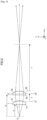
- Fig. 1 is a diagram schematically illustrating a collimation system (two-lens optical system) 100 of the present embodiment.
- the description below first deals with the x axis, y axis, and z axis shown in Fig. 1 .
- the z axis extends in the direction in which light emitted from a light source 5 travels (that is, the optical axis direction).
- the z axis thus extends in the left-right direction of Fig. 1 .
- the y axis extends in a direction orthogonal to the z axis, and extends in the up-down direction of Fig. 1 .
- the x axis extends in the direction orthogonal to the y axis and z axis.
- the collimation system 100 is configured to collimate light emitted from a light source 5, and includes a first lens 1, a second lens 2, a first support base 11, a second support base 12, and a light source 5.
- the light source 5 may be understood as either being included in the collimation system 100 or not being included in the collimation system 100.
- the light source 5 may be a laser element or a light-emitting diode (LED), for example.
- the light emitted from the light source 5 is not limited to any particular wavelength. The description below assumes that the light source 5 is a laser element.
- the first lens 1 is a planoconvex lens.
- the first lens 1 has a flat surface 1a and a convex surface 1b.
- the light emitted from the light source 5 is incident on the flat surface 1a and exits from the convex surface 1b.
- the first lens 1 guides light from the light source 5 toward the second lens 2.
- the first lens 1 has a focal length f 1 .
- the first lens 1 may be a lens other than a planoconvex lens, and may be a biconvex lens, for example.
- the second lens 2 is a planoconvex lens.
- the second lens 2 has a flat surface 2a and a convex surface 2b.
- the light traveling from the first lens 1 is incident on the flat surface 2a and exits from the convex surface 2b.
- the second lens 2 has a focal length f 2 .
- the second lens 2 may be a lens other than a planoconvex lens, and may be a biconvex lens, for example.
- the description below uses (i) the term “front” about a lens to refer to the side on which light is incident and (ii) the term “back” about a lens to refer to the side from which light exits.
- the first lens 1 has a back principal plane 21
- the second lens 2 has a front principal plane 22.
- the back principal plane 21 and the front principal plane 22 are separated from each other by a separation s.
- the first lens 1 is placed on a first support base 11.
- the first support base 11 is connected to a first moving section (not shown) configured to move the first support base 11 along the z axis.
- the first moving section may alternatively be contained in the first support base 11.
- the first moving section is, for example, an actuator.
- the first support base 11 is constrained along the x axis and/or y axis.
- the first support base 11 includes a first support base component 11a and a first support base component 11b.
- the first support base component 11a and the first support base component 11b sandwich the first lens 1 by being in contact with two respective side surfaces of the first lens 1 that are different from the flat surface 1a and the convex surface 1b.
- the first support base component 11a and the first support base component 11b are configured to move together.
- the first support base component 11a and the first support base component 11b may be separate from each other or integrated with each other.
- the second lens 2 is placed on a second support base 12.
- the second support base 12 is connected to a second moving section (not shown) configured to move the second support base 12 along the x axis and/or y axis.
- the second moving section may alternatively be contained in the second support base 12.
- the second moving section is, for example, an actuator.
- the second support base 12 is constrained along the z axis.
- the flat surface 2a of the second lens 2 is in contact with the second support base 12.
- the second support base 12 is in the shape of, for example, a rectangular parallelepiped, and has an aperture 50 at its center. The light traveling from the first lens 1 is incident on the second lens 2 through the aperture 50.
- the combination of the first support base 11 and the first lens 1 and the combination of the second support base 12 and the second lens 2 may be configured as follows:
- the first support base 11 is fixed to a housing (not shown), and is thus immovable relative to the housing.
- the first lens 1 is attached to the first support base 11.
- the first lens 1 is movable within and/or on the first support base 11.
- the second support base 12 is fixed to the housing (not shown), is thus immovable relative to the housing.
- the second lens 2 is attached to the second support base 12.
- the second lens 2 is movable within and/or on the second support base 12.
- the first lens 1 and the second lens 2 are fixed respectively to the first support base 11 and the second support base 12 with use of, for example, an adhesive.
- the adhesive may, depending on the kind thereof, form a thin layer. This allows the adhesive to keep its adhesive force strong even in a case where the external environment (for example, air temperature) has changed.
- the first support base 11 may include a lens holder (not shown) configured to receive the first lens 1.
- the second support base 12 may include a lens holder (not shown) configured to receive the second lens 2.
- the first lens 1 and the second lens 2 may be fixed respectively to the first support base 11 and the second support base 12 with use of a member other than an adhesive (for example, a fastener).
- the first support base 11 constrains the movement of the first lens 1 (or the combination of the first lens 1 and the corresponding lens holder), whereas (ii) in a case where the second lens 2 has been fixed to the second support base 12, the second support base 12 constrains the movement of the second lens 2 (or the combination of the second lens 2 and the corresponding lens holder).
- the collimation system 100 may be configured such that the first support base 11 and the second support base 12 are fixed to the housing and that the first lens 1 is moved within and/or on the first support base 11, whereas the second lens 2 is moved within and/or on the second support base 12.
- This configuration is also applicable to Embodiments 2 to 6 described later.
- Embodiments 1 to 6 may each alternatively be configured as described above.
- the following description will discuss how the collimation system 100 operates.
- Light emitted from the light source 5 is incident on the first lens 1.
- the first lens 1 is movable along the z axis by means of the operation of the first support base 11.
- the first support base 11 adjusts the position of the first lens 1 along the z axis. This allows collimation adjustment to be carried out for the collimation system 100.
- the light from the light source 5 travels through the first lens 1 and is then incident on the second lens 2.
- the second lens 2 is movable along the x axis and/or y axis by means of the operation of the second support base 12.
- the second support base 12 adjusts the position of the second lens 2 along the x axis and/or y axis. This allows beam steering to be carried out for the collimation system 100.
- the collimation adjustment and beam steering for the collimation system 100 are followed by fixing the first lens 1 and the second lens 2 to the first support base 11 and the second support base 12, respectively, with use of an adhesive, for example.
- the first lens 1 may be fixed to the first support base 11 after the collimation adjustment and before the beam steering. In this case, fixing after the beam steering is for the second lens 2 to the second support base 12.
- the collimation system 100 is, as described above, configured such that the first support base 11 is used for collimation adjustment, whereas the second support base 12 is used for beam steering.
- Fig. 2 is a diagram illustrating beam-steer sensitivity.
- Fig. 3 is a graph illustrating how the focal length f 2 of the second lens 2 is related to the respective beam-steer sensitivities of the first lens 1 and second lens 2.
- Fig. 4 is a graph illustrating how the focal length f 1 of the first lens 1 is related to the respective beam-steer sensitivities of the first lens 1 and second lens 2, the graph illustrating a case where the separation (s) between the back principal plane 21 of the first lens 1 and the front principal plane 22 of the second lens 2 is changed between 0.6 mm to 2.0 mm.
- Figs. 3 and 4 assume that the two-lens device illustrated in Fig. 2 has an effective focal length f of 5 mm.
- first lens 1 As illustrated in Fig. 2 , light emitted from the light source 5 is incident on the first lens 1, and is then incident on the second lens 2.
- the following description will discuss the respective beam-steer sensitivities of the first lens 1 and second lens 2 for a case where the first lens 1 and second lens 2 are each moved in a lateral direction (that is, along the x axis or y axis).
- the two-lens device illustrated in Fig. 2 is configured such that shifting one of the lenses laterally results in a beam-steer angle expressed in Formula 1 or 2 below.
- f 2 f ⁇ f 1 ⁇ s / f 1 ⁇ f
- Figs. 3 and 4 show A) to C) below.
- the collimation system 100 has a beam-steer sensitivity significantly lower than the beam-steer sensitivity of a single-lens device.
- the collimation can be quantified on the basis of the position of the focus of a light source (for example, a laser diode).
- the collimation (c), expressed in diopters, is the inverse of the displacement v measured in meters.
- Fig. 5 is a diagram schematically illustrating a two-lens device.
- Fig. 5 shows a plane 23, which extends through the apex of the convex surface 2b of the second lens 2 and which is parallel to the flat surface 2a.
- the displacement v is the distance between the focus of the two-lens device and the plane 23.
- the collimation c is calculated on the basis of Formula 4 below.
- Z 1 is the distance between the light source 5 and the flat surface 1a
- Z 2 is the distance between the light source 5 and the flat surface 2a
- ⁇ Z 1 is a small shift of the first lens 1 from Z 1c
- ⁇ Z 2 is a small shift of the second lens 2 from Z 2c
- Z 1c is the position of the first lens 1 for perfect collimation (lcl -> 0) at the effective focal length f
- Z 2c is the position of the second lens 2 for perfect collimation (lcl -> 0) at the effective focal length f.
- Fig. 6 is a diagram schematically illustrating a two-lens device with a virtual focus.
- Fig. 6 shows light diverging from the second lens 2.
- the two-lens device illustrated in Fig. 6 has a virtual focus on a side of the first lens 1 on which side the light source is present.
- the displacement v is the distance between the virtual focus of the two-lens device and the plane 23.
- the collimation c of the virtual two-lens device illustrated in Fig. 6 can also be calculated on the basis of Formula 4.
- the collimation c of a single-lens device is calculated on the basis of Formula 5 below.
- c ⁇ z / f 2
- ⁇ z is a small shift of the lens from the position for perfect collimation.
- the collimation sensitivity of the first lens 1 in the longitudinal direction (Z direction) is calculated on the basis of Formula 6 below with reference to Formula 4.
- Fig. 7 is a graph illustrating how the focal length f 2 of the second lens 2 is related to the respective collimation sensitivities of the first lens 1 and second lens 2.
- Fig. 8 is a graph illustrating how the focal length f 1 of the first lens 1 is related to the respective collimation sensitivities of the first lens 1 and second lens 2, the graph illustrating a case where the separation (s) between the back principal plane 21 of the first lens 1 and the front principal plane 22 of the second lens 2 is changed between 0.6 mm to 2.0 mm.
- f 5 mm.
- f 2 f ⁇ f 1 ⁇ s / f 1 ⁇ f
- Figs. 7 and 8 show the following:
- the effective focal length of a collimation optical system influences the achievable spot size.
- the effective focal length sets the angular separation of collimated light from each emission area. Designing a projector including such a light source involves knowledge of the angular separation.
- a light source having a plurality of separated, individually drivable emission areas is useful for speckle reduction and/or for increasing the resolution of the display whilst keeping a high frame rate.
- the effective focal length (f) of a two-lens device is more resilient to lens fabrication tolerances than the focal length of a single-lens device.
- the effective focal length variation depends on the respective focal lengths of the first lens 1 and the second lens 2 as shown in Formula 11 below.
- ⁇ f f 1 2 f 1 ⁇ f ⁇ s f ⁇ s 2 ⁇ f 1 f 1 2 + f 1 ⁇ f 2 ff 1 + s 2 f 1 ⁇ s 2 f 1 2 f ⁇ s 2 ⁇ f 2 f 2 1 / 2
- Fig. 9 is a graph illustrating how the focal length f 1 of the first lens 1 is related to ⁇ f/ f, the graph illustrating a case where the separation (s) between the back principal plane 21 of the first lens 1 and the front principal plane 22 of the second lens 2 is changed between 0.6 mm to 2.0 mm.
- the effective focal length f is 5 mm
- ⁇ f/f indicates the fractional effective focal length change (rms).
- the focal length variation ⁇ f 1 /f 1 of the first lens 1 is 1%
- the focal length variation ⁇ f 2 /f 2 of the second lens 2 is 1%.
- the respective focal length variations of the first lens 1 and the second lens 2 are statistically independent of each other.
- the fractional effective focal length change becomes less sensitive as f 1 increases, and the fractional effective focal length becomes less sensitive as the separation (s) increases.
- the collimation system 100 is configured as described above.
- the collimation system 100 is, as described above, configured such that collimation adjustment and beam steering can be carried out independently of each other. Specifically, one of the two lenses is used for collimation adjustment, while the other lens is used for beam steering.
- the collimation system 100 is configured such that the position of the first lens 1 is adjusted with use of the first support base 11, whereas the position of the second lens 2 is adjusted with use of the second support base 12.
- the collimation system 100 is configured such that the respective positions of the first lens 1 and the second lens 2 can be adjusted with increased accuracy and that the first lens 1 and the second lens 2 can be aligned with improved tolerances as compared to a single-lens device.
- the first lens 1 is placed on the first support base 11, whereas the second lens 2 is placed on the second support base 12.
- This configuration reduces the amount of an adhesive and/or the like for fixing the first lens 1 to the first support base 11 and the second lens 2 to the second support base 12, and thereby reduces the thickness of the layer of the adhesive and/or the like. This in turn allows the collimation system 100 to be more stable against environmental changes such as the temperature.
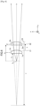
- Fig. 10 is a diagram schematically illustrating a collimation system 110 of the present embodiment.
- any member of the present invention that is identical in function to a member described for Embodiment 1 is assigned the same reference sign, and is not described again here. This applies also to Embodiments 3 and later.
- the collimation system 110 differs from the collimation system 100 in that in the collimation system 110, light emitted from the light source 5 is first incident on the second lens 2 and is then incident on the first lens 1. In terms of other configuration and operation (for example, the operation of the first support base 11 or second support base 12), the collimation system 110 is identical to the collimation system 100.
- the collimation adjustment and beam steering for the collimation system 110 are followed by fixing the first lens 1 and the second lens 2 to the first support base 11 and the second support base 12, respectively, with use of an adhesive, for example.
- the first lens 1 may be fixed to the first support base 11 after the collimation adjustment and before the beam steering. In this case, fixing after the beam steering is only for the second lens 2 to the second support base 12.
- the collimation system 110 will achieve the advantages (a) and (b) over a single-lens device on the assumption that (i) the collimation system 110 (two-lens device) satisfies Formula 12 below and (ii) the effective focal length of the collimation system 110 is equal to the focal length of the single-lens device.
- the effective focal length variation depends on the respective focal lengths of the first lens 1 and the second lens 2 as shown in Formula 13 below.
- ⁇ f f f 1 ⁇ f 2 f 2 ⁇ f 2 f 2 2 + ⁇ f 1 f 1 2 1 / 2
- Fig. 11 is a graph illustrating how the focal length f 1 of the first lens 1 is related to ⁇ f/f. ⁇ f/f indicates the fractional effective focal length change (rms).
- the effective focal length f of the two-lens device is 5 mm.
- the focal length variation ⁇ f 1 /f 1 of the first lens 1 is 1%, and the focal length variation ⁇ f 2 /f 2 of the second lens 2 is 1%.
- the respective focal length variations of the first lens 1 and the second lens 2 are statistically independent of each other.
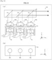
- Fig. 12 is a diagram schematically illustrating a beam combining module 120 of the present embodiment.
- the beam combining module 120 includes a collimation system 100a, a collimation system 100b, a collimation system 100c, a housing 30, a mirror 31a, a dichroic mirror 31b, and a dichroic mirror 31c.
- the collimation system 100a, the collimation system 100b, and the collimation system 100c each correspond to the collimation system 100 of Embodiment 1.
- the beam combining module 120 includes only one second support base 12a. This point will be described later.
- the mirror 31a, the dichroic mirror 31b, and the dichroic mirror 31c are contained in the housing 30.
- the housing 30 may be made of glass so the combination 30, 31a, 31b, 31c form a dichroic prism.
- the collimation system 100a, the collimation system 100b, and the collimation system 100c are provided respectively with a light source 5a, a light source 5b, and a light source 5c.
- the light source 5a, the light source 5b, and the light source 5c are configured to emit light having respective colors different from each other.
- the light source 5a is configured to emit red light
- the light source 5b is configured to emit green light
- the light source 5c is configured to emit blue light.
- the light source 5a, the light source 5b, and the light source 5c do not need to be placed on the same plane.
- the beam combining module 120 includes only one second support base 12a.
- the three second lenses 2 share a single second support base 12a. The three second lenses 2 are thus moved together by means of the operation of the second support base 12a.
- the second support base 12a has an aperture 50a, an aperture 50b, and an aperture 50c.
- the aperture 50a corresponds to the collimation system 100a.
- the aperture 50b corresponds to the collimation system 100b.
- the aperture 50c corresponds to the collimation system 100c.
- Light emitted from the light source 5a travels through the collimation system 100a to be reflected on the mirror 31a.
- the light reflected on the mirror 31a travels through the dichroic mirror 31b and the dichroic mirror 31c to exit from the beam combining module 120.
- Light emitted from the light source 5b travels through the collimation system 100b to be reflected on the dichroic mirror 31b.
- the light reflected on the dichroic mirror 31b travels through the dichroic mirror 31c to exit from the beam combining module 120.
- Light emitted from the light source 5c travels through the collimation system 100c to be reflected on the dichroic mirror 31c.
- the light reflected on the dichroic mirror 31c exits from the beam combining module 120.
- Light with mixed colors of red, green, and blue is emitted to the outside of the beam combining module 120 as described above.
- the respective colors of light emitted by the light source 5a, the light source 5b, and the light source 5c are not limited to any particular ones.
- the light source 5a, the light source 5b, and the light source 5c may each be a laser configured to emit, for example, an ultraviolet ray, an X ray, or an infrared ray.
- the lens material (glass or plastic) has a refractive index that varies according to the wavelength of light incident on the lens. It follows that the properties of an image formed also vary according to the wavelength.
- chromatic aberration refers to how an image varies according to the wavelength of light incident on the lens.
- the beam combining module 120 is configured to, in view of chromatic aberration, adjust the separation between the first lens 1 and the second lens 2 of each collimation system in correspondence with the wavelength of light emitted from the corresponding light source 5. This configuration allows each collimation system to have an intended effective focal length.
- the beam combining module 120 is configured to adjust (1) the respective positions of the light sources 5a to 5c in correspondence with the respective wavelengths of light emitted from the light sources 5a to 5c, (2) the respective positions of the three first lenses 1 individually, and/or (3) the respective positions of the three second lenses 2 together by means of the operation of the second support base 12a.
- This configuration allows the beam combining module 120 to (i) correct chromatic aberration of each of the collimation system 100a, the collimation system 100b, and the collimation system 100c and (ii) emit light with mixed colors of red, green, and blue to the outside of the beam combining module 120.
- the beam combining module 120 includes three collimation systems 100.
- the beam combining module 120 may include any plurality (that is, any number that is two or more) of collimation systems 100.
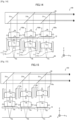
- Fig. 13 is a diagram schematically illustrating a beam combining module 130 of the present embodiment.
- the beam combining module 130 includes a collimation system 110a, a collimation system 110b, a collimation system 110c, a housing 30, a mirror 31a, a dichroic mirror 31b, and a dichroic mirror 31c.
- the collimation system 110a, the collimation system 110b, and the collimation system 110c each correspond to the collimation system 110 of Embodiment 2.
- the beam combining module 130 includes only one second support base 12. This point will be described later.
- the collimation system 110a, the collimation system 110b, and the collimation system 110c are provided respectively with a light source 5a, a light source 5b, and a light source 5c.
- the light source 5a, the light source 5b, and the light source 5c are configured to emit light having respective colors different from each other.
- the light source 5a is configured to emit red light
- the light source 5b is configured to emit green light
- the light source 5c is configured to emit blue light.
- the beam combining module 130 includes only one second support base 12.
- the three second lenses 2 share a single second support base 12a. The three second lenses 2 are thus moved together by means of the operation of the second support base 12a.
- the second support base 12a has an aperture 50a, an aperture 50b, and an aperture 50c.
- the aperture 50a corresponds to the collimation system 110a.
- the aperture 50b corresponds to the collimation system 110b.
- the aperture 50c corresponds to the collimation system 110c.
- Light emitted from the light source 5a travels through the collimation system 110a to be reflected on the mirror 31a.
- the light reflected on the mirror 31a travels through the dichroic mirror 31b and the dichroic mirror 31c to exit from the beam combining module 130.
- Light emitted from the light source 5b travels through the collimation system 110b to be reflected on the dichroic mirror 31b.
- the light reflected on the dichroic mirror 31b travels through the dichroic mirror 31c to exit from the beam combining module 130.
- Light emitted from the light source 5c travels through the collimation system 110c to be reflected on the dichroic mirror 31c.
- Light with mixed colors of red, green, and blue is emitted to the outside of the beam combining module 130 as described above.
- the beam combining module 130 is configured to adjust (1) the respective positions of the light sources 5a to 5c in correspondence with the respective wavelengths of light emitted from the light sources 5a to 5c, (2) the respective positions of the three first lenses 1 individually, and/or (3) the respective positions of the three second lenses 2 together by means of the operation of the second support base 12a.
- This configuration allows the beam combining module 130 to (i) correct chromatic aberration of each of the collimation system 110a, the collimation system 110b, and the collimation system 110c and (ii) emit light with mixed colors of red, green, and blue to the outside of the beam combining module 130.
- the beam combining module 130 includes three collimation systems 110.
- the beam combining module 130 may include any plurality (that is, any number that is two or more) of collimation systems 110.
- Fig. 14 is a diagram schematically illustrating a beam combining module 140 of the present embodiment.
- the beam combining module 140 differs from the beam combining module 120 of Embodiment 3 on points (1) and (2) below.
- the beam combining module 140 which is configured as described in (1) and (2) above, can be compact. This in turn allows a device (for example, a projector) including the beam combining module 140 to be compact as well. Further, since the light source 5a, the light source 5b, and the light source 5c are placed on the same plane 60, the beam combining module 140 can be handled easily. As a result, a device designed to include the beam combining module 140 can be assembled easily and rapidly.
- the beam combining module 140 includes three collimation systems 100.
- the beam combining module 140 may include any plurality (that is, any number that is two or more) of collimation systems 100.
- Fig. 15 is a diagram schematically illustrating a beam combining module 150 of the present embodiment.
- the beam combining module 150 differs from the beam combining module 130 of Embodiment 4 on points (1) and (2) below.
- the beam combining module 150 which is configured as described in (1) and (2) above, can be compact. This in turn allows a device (for example, a projector) including the beam combining module 150 to be compact as well. Further, since the light source 5a, the light source 5b, and the light source 5c are placed on the same plane 60, the beam combining module 150 can be handled easily. As a result, a device designed to include the beam combining module 150 can be assembled easily and rapidly.
- the beam combining module 150 includes three collimation systems 110.
- the beam combining module 150 may include any plurality (that is, any number that is two or more) of collimation systems 110.
- the collimation system 100, 110 is, as described above, configured such that collimation adjustment and beam steering can be carried out independently of each other. Specifically, one of the two lenses is used for collimation adjustment, while the other lens is used for beam steering.
- the collimation system 100, 110 is configured such that the respective positions of the first lens 1 and the second lens 2 can be adjusted with increased accuracy and that the first lens 1 and the second lens 2 can be aligned with improved tolerances as compared to a single-lens device.
- the collimation system 100, 110 enjoys various benefits that are unachievable by conventional single-lens devices.
- Such a beam combining module is any of the beam combining modules 120 to 150 of Embodiments 3 to 6 as proposed.
- the beam combining modules 120 to 150 are each advantageously configured to (1) enjoy the benefits of the collimation system 100, 110, (2) efficiently generate light having a plurality of colors that are not limited to any particular ones and emit such generated light to the outside of the beam combining module, and (3) be compact.
- the beam combining modules 120 to 150 are each suitably usable in, for example, a laser projection system.
- the laser projection system is, in particular, suitably a small laser projection system including a MEMS scanning mirror to create an image.
Landscapes
- Physics & Mathematics (AREA)
- General Physics & Mathematics (AREA)
- Optics & Photonics (AREA)
- Lens Barrels (AREA)
- Lenses (AREA)
- Projection Apparatus (AREA)
- Mounting And Adjusting Of Optical Elements (AREA)
Description
- The present invention relates to a two-lens optical system, a beam combining module, a projector, and a method for assembling a two-lens optical system.
- In a case where an optical device including a lens has a light combining efficiency that changes by a large amount with respect to the amount of movement of the lens, it is not easy to adjust the light combining efficiency so that the light combining efficiency is within a suitable range. The optical device thus desirably has a light combining efficiency that changes by only a small amount with respect to the amount of movement of the lens. The optical device, in other words, desirably has a small lens positioning sensitivity.
- The description below uses (1) the term "single-lens device" to refer to an optical device including a single lens to collimate or focus light emitted from a light source and (2) the term "two-lens device" to refer to an optical device including two lenses to collimate or focus light emitted from a light source. On the assumption that the focal length of a single-lens device and the effective focal length of a two-lens device are equal to each other, the two-lens device normally has a lower lens positioning sensitivity.
-
Patent Literatures 1 to 3 and Non-patentLiterature 1 each disclose a two-lens device. -
- PTL 1:
U.S. Patent No. 4,823,334 - PTL 2:
U.S. Patent No. 6,055,113 - PTL 3:
U.S. Patent No. 6,974,939 - From
JP H02 119002 A - The paper by Baranski Maciej et al.: "Micro-optical design of a three-dimensional microlens scanner for vertically integrated micro-opto-electro-mechanical systems". Applied Optics, vol. 54, no. 22, 30 July 2015, page 6924, US, ISSN 0003-6935, DOI: 10.1364/AO.54.006924, presents the optical design of a miniature 3D scanning system, which is fully compatible with the vertical integration technology of micro-optical-electro-mechanical systems (MOEMS).
-
US 2005/28097 A1 relates to an optical pickup lens device that includes, in the order from the light source side, collimating means for converting a bundle of rays into parallel rays or predetermined convergent or divergent rays, the collimating means being movably held along a direction of an optical axis of a bundle of rays emitted from a light source; an aberration correcting element for allowing a bundle of rays emitted from the collimating means to be transmitted therethrough; and an objective lens element having a numerical aperture of 0.8 or more, and converging a bundle of rays coming from the aberration correcting element onto the information recording medium to form a spot. The aberration correcting element and the objective lens element are integrally held together in a direction orthogonal to the optical axis so as to perform tracking on the information recording medium, and satisfy predetermined conditions. -
US 9 116 421 B1 - Unfortunately, none of the two-lens devices disclosed in
Patent Literatures 1 to 3 and Non-patentLiterature 1 is configured to carry out collimation adjustment and beam steering in view of the balance between collimation sensitivity and beam steering sensitivity. In that regard, the optical devices disclosed inPatent Literatures 1 to 3 and Non-patentLiterature 1 leave room for improvement in terms of lens positioning sensitivity. - The present invention has been accomplished in view of the above issue. It is an object of the present invention to provide (i) a two-lens optical system, (ii) a beam combining module, (iii) a projector, and (iv) a method for assembling a two-lens optical system each of which allows for an improved lens positioning sensitivity.
- The above problems are solved by the subject-matter of the independent claims.
- In order to attain the above object, a two-lens optical system in accordance with an embodiment of the present invention is a two-lens optical system, including: a first lens for use in collimation adjustment, the first lens being configured to move along only an optical axis of light emitted from a light source; and a second lens for use in beam steering, the second lens being configured to move along only two axes perpendicular to the optical axis.
- With the above configuration, the two-lens optical system is configured such that the first lens is used for collimation adjustment, whereas the second lens is used for beam steering.
- The above configuration thus allows each of the first lens and the second lens to have a small positioning sensitivity. The two-lens optical system is configured such that the respective positions of the first lens and the second lens can be adjusted with increased accuracy and that the first lens and the second lens can be aligned with improved tolerances as compared to a single-lens device.
- In order to attain the above object, a method in accordance with an embodiment of the present invention for assembling a two-lens optical system is a method for assembling a two-lens optical system, the two-lens optical system including: a first lens; a first support base configured to constrain movement of the first lens in such a manner that the first lens is movable along only an optical axis of light emitted from a light source; a second lens; and a second support base configured to constrain movement of the second lens in such a manner that the second lens is movable along only two axes perpendicular to the optical axis, the method comprising the steps of: (a) moving the first lens along the optical axis for collimation adjustment of the two-lens optical system; (b) after the step (a), moving the second lens along at least one of the two axes for beam steering of the two-lens optical system; (c) after the step (a) or (b), fixing the first lens to the first support base; and (d) after the step (b), fixing the second lens to the second support base.
- In order to attain the above object, a method in accordance with an embodiment of the present invention for assembling a two-lens optical system is a method for assembling a two-lens optical system, the two-lens optical system including: a first support base configured to move along only an optical axis of light emitted from a light source, a first lens configured to move together with the first support base; a second support base configured to move along only two axes perpendicular to the optical axis; and a second lens configured to move together with the second support base, the method including the steps of: (a) moving the first support base for collimation adjustment of the two-lens optical system; (b) after the step (a), moving the second support base for beam steering of the two-lens optical system; (c) after the step (a) or (b), fixing the first lens to the first support base; and (d) after the step (b), fixing the second lens to the second support base.
- The above arrangement makes it possible to easily assemble a two-lens optical system capable of producing the above effects.
- An embodiment of the present invention makes it possible to provide (i) a two-lens optical system, (ii) a beam combining module, (iii) a projector, and (iv) a method for assembling a two-lens optical system each of which allows for an improved lens positioning sensitivity.
-
- [
fig.1]Fig. 1 is a diagram schematically illustrating a collimation system of an embodiment of the present invention. - [
fig.2]Fig. 2 is a diagram illustrating beam-steer sensitivity. - [
fig.3]Fig. 3 is a graph illustrating how the focal length f2 of a second lens is related to the respective beam-steer sensitivities of a first lens and the second lens. - [
fig.4]Fig. 4 is a graph illustrating how the focal length f1 of a first lens is related to the respective beam-steer sensitivities of the first lens and a second lens, the graph illustrating a case where the separation (s) between a back principal plane of the first lens and a front principal plane of the second lens is changed between 0.6 mm to 2.0 mm. - [
fig.5]Fig. 5 is a diagram schematically illustrating a two-lens device. - [
fig.6]Fig. 6 is a diagram schematically illustrating a two-lens device with a virtual focus. - [
fig.7]Fig. 7 is a graph illustrating how the focal length f2 of a second lens is related to the respective collimation sensitivities of a first lens and the second lens. - [
fig.8]Fig. 8 is a graph illustrating how the focal length f1 of a first lens is related to the respective collimation sensitivities of the first lens and a second lens, the graph illustrating a case where the separation (s) between a back principal plane of the first lens and a front principal plane of the second lens is changed between 0.6 mm to 2.0 mm. - [
fig.9]Fig. 9 is a graph illustrating how the focal length f1 of a first lens is related to Δf/ f, the graph illustrating a case where the separation (s) between a back principal plane of the first lens and a front principal plane of the second lens is changed between 0.6 mm to 2.0 mm. - [
fig.10]Fig. 10 is a diagram schematically illustrating a collimation system of an embodiment. - [
fig.11] Fig. 11 is a graph illustrating how the focal length f1 of a first lens is related to Δf/f. - [
fig.12]Fig. 12 is a diagram schematically illustrating a collimation system of an embodiment. - [
fig.13]Fig. 13 is a diagram schematically illustrating a collimation system of an embodiment. - [
fig.14]Fig. 14 is a diagram schematically illustrating a collimation system of an embodiment. - [
fig.15]Fig. 15 is a diagram schematically illustrating a collimation system of an embodiment. - The following description will discuss an embodiment of the present invention with reference to, for example,
Fig. 1. Fig. 1 is a diagram schematically illustrating a collimation system (two-lens optical system) 100 of the present embodiment. - The description below first deals with the x axis, y axis, and z axis shown in
Fig. 1 . The z axis extends in the direction in which light emitted from alight source 5 travels (that is, the optical axis direction). The z axis thus extends in the left-right direction ofFig. 1 . The y axis extends in a direction orthogonal to the z axis, and extends in the up-down direction ofFig. 1 . The x axis extends in the direction orthogonal to the y axis and z axis. - The
collimation system 100 is configured to collimate light emitted from alight source 5, and includes afirst lens 1, asecond lens 2, afirst support base 11, asecond support base 12, and alight source 5. Thelight source 5 may be understood as either being included in thecollimation system 100 or not being included in thecollimation system 100. - The
light source 5 may be a laser element or a light-emitting diode (LED), for example. The light emitted from thelight source 5 is not limited to any particular wavelength. The description below assumes that thelight source 5 is a laser element. - The
first lens 1 is a planoconvex lens. Thefirst lens 1 has aflat surface 1a and aconvex surface 1b. The light emitted from thelight source 5 is incident on theflat surface 1a and exits from theconvex surface 1b. Thefirst lens 1 guides light from thelight source 5 toward thesecond lens 2. Thefirst lens 1 has a focal length f1. Thefirst lens 1 may be a lens other than a planoconvex lens, and may be a biconvex lens, for example. - The
second lens 2 is a planoconvex lens. Thesecond lens 2 has aflat surface 2a and aconvex surface 2b. The light traveling from thefirst lens 1 is incident on theflat surface 2a and exits from theconvex surface 2b. Thesecond lens 2 has a focal length f2 . Thesecond lens 2 may be a lens other than a planoconvex lens, and may be a biconvex lens, for example. - The description below uses (i) the term "front" about a lens to refer to the side on which light is incident and (ii) the term "back" about a lens to refer to the side from which light exits. In the description below, the
first lens 1 has a backprincipal plane 21, and thesecond lens 2 has a frontprincipal plane 22. The backprincipal plane 21 and the frontprincipal plane 22 are separated from each other by a separation s. - The
first lens 1 is placed on afirst support base 11. Thefirst support base 11 is connected to a first moving section (not shown) configured to move thefirst support base 11 along the z axis. The first moving section may alternatively be contained in thefirst support base 11. The first moving section is, for example, an actuator. Thefirst support base 11 is constrained along the x axis and/or y axis. - The
first support base 11 includes a firstsupport base component 11a and a firstsupport base component 11b. The firstsupport base component 11a and the firstsupport base component 11b sandwich thefirst lens 1 by being in contact with two respective side surfaces of thefirst lens 1 that are different from theflat surface 1a and theconvex surface 1b. The firstsupport base component 11a and the firstsupport base component 11b are configured to move together. The firstsupport base component 11a and the firstsupport base component 11b may be separate from each other or integrated with each other. - The
second lens 2 is placed on asecond support base 12. Thesecond support base 12 is connected to a second moving section (not shown) configured to move thesecond support base 12 along the x axis and/or y axis. The second moving section may alternatively be contained in thesecond support base 12. The second moving section is, for example, an actuator. Thesecond support base 12 is constrained along the z axis. - The
flat surface 2a of thesecond lens 2 is in contact with thesecond support base 12. Thesecond support base 12 is in the shape of, for example, a rectangular parallelepiped, and has anaperture 50 at its center. The light traveling from thefirst lens 1 is incident on thesecond lens 2 through theaperture 50. - The combination of the
first support base 11 and thefirst lens 1 and the combination of thesecond support base 12 and thesecond lens 2 may be configured as follows: Thefirst support base 11 is fixed to a housing (not shown), and is thus immovable relative to the housing. Thefirst lens 1 is attached to thefirst support base 11. Thefirst lens 1 is movable within and/or on thefirst support base 11. Similarly, thesecond support base 12 is fixed to the housing (not shown), is thus immovable relative to the housing. Thesecond lens 2 is attached to thesecond support base 12. Thesecond lens 2 is movable within and/or on thesecond support base 12. After collimation adjustment and beam steering (described later), thefirst lens 1 and thesecond lens 2 are fixed respectively to thefirst support base 11 and thesecond support base 12 with use of, for example, an adhesive. The adhesive may, depending on the kind thereof, form a thin layer. This allows the adhesive to keep its adhesive force strong even in a case where the external environment (for example, air temperature) has changed. Thefirst support base 11 may include a lens holder (not shown) configured to receive thefirst lens 1. Thesecond support base 12 may include a lens holder (not shown) configured to receive thesecond lens 2. Thefirst lens 1 and thesecond lens 2 may be fixed respectively to thefirst support base 11 and thesecond support base 12 with use of a member other than an adhesive (for example, a fastener). - With the above configuration, (i) in a case where the
first lens 1 has been fixed to thefirst support base 11, thefirst support base 11 constrains the movement of the first lens 1 (or the combination of thefirst lens 1 and the corresponding lens holder), whereas (ii) in a case where thesecond lens 2 has been fixed to thesecond support base 12, thesecond support base 12 constrains the movement of the second lens 2 (or the combination of thesecond lens 2 and the corresponding lens holder). - As described above, the
collimation system 100 may be configured such that thefirst support base 11 and thesecond support base 12 are fixed to the housing and that thefirst lens 1 is moved within and/or on thefirst support base 11, whereas thesecond lens 2 is moved within and/or on thesecond support base 12. This configuration is also applicable toEmbodiments 2 to 6 described later. - Although the description below assumes that the
first support base 11 and thesecond support base 12 are movable relative to the housing,Embodiments 1 to 6 may each alternatively be configured as described above. - The following description will discuss how the
collimation system 100 operates. Light emitted from thelight source 5 is incident on thefirst lens 1. Thefirst lens 1 is movable along the z axis by means of the operation of thefirst support base 11. In other words, thefirst support base 11 adjusts the position of thefirst lens 1 along the z axis. This allows collimation adjustment to be carried out for thecollimation system 100. - The light from the
light source 5 travels through thefirst lens 1 and is then incident on thesecond lens 2. Thesecond lens 2 is movable along the x axis and/or y axis by means of the operation of thesecond support base 12. In other words, thesecond support base 12 adjusts the position of thesecond lens 2 along the x axis and/or y axis. This allows beam steering to be carried out for thecollimation system 100. - The collimation adjustment and beam steering for the
collimation system 100 are followed by fixing thefirst lens 1 and thesecond lens 2 to thefirst support base 11 and thesecond support base 12, respectively, with use of an adhesive, for example. Alternatively, thefirst lens 1 may be fixed to thefirst support base 11 after the collimation adjustment and before the beam steering. In this case, fixing after the beam steering is for thesecond lens 2 to thesecond support base 12. - The
collimation system 100 is, as described above, configured such that thefirst support base 11 is used for collimation adjustment, whereas thesecond support base 12 is used for beam steering. - The following description will discuss beam-steer sensitivity with reference to
Figs. 2 to 4 .Fig. 2 is a diagram illustrating beam-steer sensitivity.Fig. 3 is a graph illustrating how the focal length f2 of thesecond lens 2 is related to the respective beam-steer sensitivities of thefirst lens 1 andsecond lens 2.Fig. 4 is a graph illustrating how the focal length f1 of thefirst lens 1 is related to the respective beam-steer sensitivities of thefirst lens 1 andsecond lens 2, the graph illustrating a case where the separation (s) between the backprincipal plane 21 of thefirst lens 1 and the frontprincipal plane 22 of thesecond lens 2 is changed between 0.6 mm to 2.0 mm.Figs. 3 and4 assume that the two-lens device illustrated inFig. 2 has an effective focal length f of 5 mm. - As illustrated in
Fig. 2 , light emitted from thelight source 5 is incident on thefirst lens 1, and is then incident on thesecond lens 2. The following description will discuss the respective beam-steer sensitivities of thefirst lens 1 andsecond lens 2 for a case where thefirst lens 1 andsecond lens 2 are each moved in a lateral direction (that is, along the x axis or y axis). - The two-lens device illustrated in
Fig. 2 is configured such that shifting one of the lenses laterally results in a beam-steer angle expressed inFormula - 1) The beam-steer sensitivity of the
first lens 1 for a case where thefirst lens 1 has been shifted laterally
- 2) The beam-steer sensitivity of the
second lens 2 for a case where thesecond lens 2 has been shifted laterally
- Once f1 and s have been determined, f2 can be calculated on the basis of
Formula 3 below.
-
Figs. 3 and4 show A) to C) below. - A) As f1 increases, the beam-steer sensitivity of the
first lens 1 decreases. - B) As f1 increases, f2 decreases. As f2 decreases, the beam-steer sensitivity of the
second lens 2 increases. - C) In a case where f1 = f = 5 mm in a single-lens device, the beam-steer sensitivity of the lens is indicated by ST1. In a case where f1 is approximately 9 mm in a two-lens device, the respective beam-steer sensitivities of a
first lens 1 andsecond lens 2 are both approximately 50% the beam-steer sensitivity of a single-lens device. - As described above, the
collimation system 100 has a beam-steer sensitivity significantly lower than the beam-steer sensitivity of a single-lens device. - The following description will discuss collimation sensitivity of the
collimation system 100. The collimation can be quantified on the basis of the position of the focus of a light source (for example, a laser diode). The collimation (c), expressed in diopters, is the inverse of the displacement v measured in meters. -
Fig. 5 is a diagram schematically illustrating a two-lens device.Fig. 5 shows aplane 23, which extends through the apex of theconvex surface 2b of thesecond lens 2 and which is parallel to theflat surface 2a. The displacement v is the distance between the focus of the two-lens device and theplane 23. In this case, the collimation c is calculated on the basis of Formula 4 below.
light source 5 and theflat surface 1a, Z2 is the distance between thelight source 5 and theflat surface 2a, ΔZ1 is a small shift of thefirst lens 1 from Z1c, ΔZ2 is a small shift of thesecond lens 2 from Z2c, Z1c is the position of thefirst lens 1 for perfect collimation (lcl -> 0) at the effective focal length f, and Z2c is the position of thesecond lens 2 for perfect collimation (lcl -> 0) at the effective focal length f. - The collimation c of a two-lens device with a virtual focus can also be calculated on the basis of Formula 4.
Fig. 6 is a diagram schematically illustrating a two-lens device with a virtual focus.Fig. 6 shows light diverging from thesecond lens 2. The two-lens device illustrated inFig. 6 has a virtual focus on a side of thefirst lens 1 on which side the light source is present. The displacement v is the distance between the virtual focus of the two-lens device and theplane 23. The collimation c of the virtual two-lens device illustrated inFig. 6 can also be calculated on the basis of Formula 4. - The collimation c of a single-lens device is calculated on the basis of
Formula 5 below.
- The collimation sensitivity of the
first lens 1 in the longitudinal direction (Z direction) is calculated on the basis ofFormula 6 below with reference to Formula 4.
- Similarly, the collimation sensitivity of the
second lens 2 in the longitudinal direction (Z direction) is calculated on the basis of Formula 7 below.
- The above calculations result in
Figs. 7 and 8. Fig. 7 is a graph illustrating how the focal length f2 of thesecond lens 2 is related to the respective collimation sensitivities of thefirst lens 1 andsecond lens 2.Fig. 8 is a graph illustrating how the focal length f1 of thefirst lens 1 is related to the respective collimation sensitivities of thefirst lens 1 andsecond lens 2, the graph illustrating a case where the separation (s) between the backprincipal plane 21 of thefirst lens 1 and the frontprincipal plane 22 of thesecond lens 2 is changed between 0.6 mm to 2.0 mm. InFigs. 7 and 8 , f = 5 mm. - Once f1 and s have been determined, f2 can be calculated on the basis of
Formula 3 below.
-
Figs. 7 and 8 show the following: - A) As f1 increases, the collimation sensitivity of the
first lens 1 decreases. - B) As f1 increases, f2 decreases. As f2 decreases, the collimation sensitivity of the
second lens 2 increases. - The above results show A) to C) below.
- A) In a case where one lens of a two-lens device has been adjusted for collimation, and the other lens has been adjusted for beam steering, the collimation sensitivity and the beam-steer sensitivity need to be balanced. In the present embodiment, increasing the focal length f1 of the
first lens 1 decreases the collimation sensitivity of thefirst lens 1 and increases the beam-steer sensitivity of thesecond lens 2. - B) A two-lens device is desirably low in both collimation sensitivity and beam-steer sensitivity. The choice of the focal length f1 of the
first lens 1 can lower the collimation sensitivity or beam-steer sensitivity. Similarly, the choice of the separation s between the backprincipal plane 21 of thefirst lens 1 and the frontprincipal plane 22 of thesecond lens 2 can, to an extent lesser than the focal length f1 of thefirst lens 1, lower the collimation sensitivity or beam-steer sensitivity as well. - C) The
collimation system 100 will achieve the advantages (a) and (b) over a single-lens device on the assumption that (i) the collimation system 100 (two-lens device) satisfies Formula 9 below and (ii) the effective focal length of thecollimation system 100 is equal to the focal length of the single-lens device. - (a) The collimation sensitivity is lower than that of the single-lens device by more than 25%.
- (b) The beam-steer sensitivity is lower than that of the single-lens device by more than 33%.

- With reference to
Formula 3, the effective focal length is expressed as inFormula 10 below.
- The effective focal length of a collimation optical system influences the achievable spot size. In a case where a light source has a plurality of separated emission areas for emitting light, the effective focal length sets the angular separation of collimated light from each emission area. Designing a projector including such a light source involves knowledge of the angular separation. A light source having a plurality of separated, individually drivable emission areas is useful for speckle reduction and/or for increasing the resolution of the display whilst keeping a high frame rate.
- The effective focal length (f) of a two-lens device is more resilient to lens fabrication tolerances than the focal length of a single-lens device. After collimation adjustment of the
first lens 1, the effective focal length variation depends on the respective focal lengths of thefirst lens 1 and thesecond lens 2 as shown inFormula 11 below.
-
Fig. 9 is a graph illustrating how the focal length f1 of thefirst lens 1 is related to Δf/ f, the graph illustrating a case where the separation (s) between the backprincipal plane 21 of thefirst lens 1 and the frontprincipal plane 22 of thesecond lens 2 is changed between 0.6 mm to 2.0 mm. - In
Fig. 9 , the effective focal length f is 5 mm, and Δf/f indicates the fractional effective focal length change (rms). The focal length variation Δf1/f1 of thefirst lens 1 is 1%, and the focal length variation Δf2/f2 of thesecond lens 2 is 1%. The respective focal length variations of thefirst lens 1 and thesecond lens 2 are statistically independent of each other. - As shown in
Fig. 9 , the fractional effective focal length change becomes less sensitive as f1 increases, and the fractional effective focal length becomes less sensitive as the separation (s) increases. - The
collimation system 100 is configured as described above. Thecollimation system 100 is, as described above, configured such that collimation adjustment and beam steering can be carried out independently of each other. Specifically, one of the two lenses is used for collimation adjustment, while the other lens is used for beam steering. - The
collimation system 100 is configured such that the position of thefirst lens 1 is adjusted with use of thefirst support base 11, whereas the position of thesecond lens 2 is adjusted with use of thesecond support base 12. - This configuration allows each of the
first lens 1 and thesecond lens 2 to have a small positioning sensitivity. Thecollimation system 100 is configured such that the respective positions of thefirst lens 1 and thesecond lens 2 can be adjusted with increased accuracy and that thefirst lens 1 and thesecond lens 2 can be aligned with improved tolerances as compared to a single-lens device. - The
first lens 1 is placed on thefirst support base 11, whereas thesecond lens 2 is placed on thesecond support base 12. This configuration reduces the amount of an adhesive and/or the like for fixing thefirst lens 1 to thefirst support base 11 and thesecond lens 2 to thesecond support base 12, and thereby reduces the thickness of the layer of the adhesive and/or the like. This in turn allows thecollimation system 100 to be more stable against environmental changes such as the temperature. - The following description will discuss a
collimation system 110 ofEmbodiment 2 with reference toFig. 10. Fig. 10 is a diagram schematically illustrating acollimation system 110 of the present embodiment. For convenience of description, any member of the present invention that is identical in function to a member described forEmbodiment 1 is assigned the same reference sign, and is not described again here. This applies also toEmbodiments 3 and later. - The
collimation system 110 differs from thecollimation system 100 in that in thecollimation system 110, light emitted from thelight source 5 is first incident on thesecond lens 2 and is then incident on thefirst lens 1. In terms of other configuration and operation (for example, the operation of thefirst support base 11 or second support base 12), thecollimation system 110 is identical to thecollimation system 100. - The collimation adjustment and beam steering for the
collimation system 110 are followed by fixing thefirst lens 1 and thesecond lens 2 to thefirst support base 11 and thesecond support base 12, respectively, with use of an adhesive, for example. Alternatively, thefirst lens 1 may be fixed to thefirst support base 11 after the collimation adjustment and before the beam steering. In this case, fixing after the beam steering is only for thesecond lens 2 to thesecond support base 12. - The
collimation system 110 will achieve the advantages (a) and (b) over a single-lens device on the assumption that (i) the collimation system 110 (two-lens device) satisfiesFormula 12 below and (ii) the effective focal length of thecollimation system 110 is equal to the focal length of the single-lens device. - (a) The collimation sensitivity is lower than that of the single-lens device by not less than 25%.
- (b) The beam-steer sensitivity is lower than that of the single-lens device by not less than 33%.

- After collimation adjustment of the
first lens 1, the effective focal length variation depends on the respective focal lengths of thefirst lens 1 and thesecond lens 2 as shown in Formula 13 below.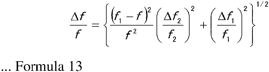
-
Fig. 11 is a graph illustrating how the focal length f1 of thefirst lens 1 is related to Δf/f. Δf/f indicates the fractional effective focal length change (rms). The effective focal length f of the two-lens device is 5 mm. The focal length variation Δf1/f1 of thefirst lens 1 is 1%, and the focal length variation Δf2/f2 of thesecond lens 2 is 1%. The respective focal length variations of thefirst lens 1 and thesecond lens 2 are statistically independent of each other. - As shown in
Fig. 11 , the fractional effective focal length becomes more sensitive as f 1 increases. A comparison between the collimation system 100 (Embodiment 1) and the collimation system 110 (Embodiment 2) thus shows that thecollimation system 100 is more suitable for a projector. - The following description will discuss a beam combining module 120 of
Embodiment 3 with reference toFig. 12. Fig. 12 is a diagram schematically illustrating a beam combining module 120 of the present embodiment. - The beam combining module 120 includes a
collimation system 100a, acollimation system 100b, acollimation system 100c, ahousing 30, amirror 31a, adichroic mirror 31b, and adichroic mirror 31c. - The
collimation system 100a, thecollimation system 100b, and thecollimation system 100c each correspond to thecollimation system 100 ofEmbodiment 1. However, the beam combining module 120 includes only onesecond support base 12a. This point will be described later. Themirror 31a, thedichroic mirror 31b, and thedichroic mirror 31c are contained in thehousing 30. Thehousing 30 may be made of glass so thecombination - The
collimation system 100a, thecollimation system 100b, and thecollimation system 100c are provided respectively with alight source 5a, alight source 5b, and alight source 5c. Thelight source 5a, thelight source 5b, and thelight source 5c are configured to emit light having respective colors different from each other. For instance, thelight source 5a is configured to emit red light, thelight source 5b is configured to emit green light, and thelight source 5c is configured to emit blue light. InEmbodiment 3, thelight source 5a, thelight source 5b, and thelight source 5c do not need to be placed on the same plane. - As mentioned above, the beam combining module 120 includes only one
second support base 12a. In other words, the threesecond lenses 2 share a singlesecond support base 12a. The threesecond lenses 2 are thus moved together by means of the operation of thesecond support base 12a. - The
second support base 12a has anaperture 50a, anaperture 50b, and anaperture 50c. Theaperture 50a corresponds to thecollimation system 100a. Theaperture 50b corresponds to thecollimation system 100b. Theaperture 50c corresponds to thecollimation system 100c. - Light emitted from the
light source 5a travels through thecollimation system 100a to be reflected on themirror 31a. The light reflected on themirror 31a travels through thedichroic mirror 31b and thedichroic mirror 31c to exit from the beam combining module 120. - Light emitted from the
light source 5b travels through thecollimation system 100b to be reflected on thedichroic mirror 31b. The light reflected on thedichroic mirror 31b travels through thedichroic mirror 31c to exit from the beam combining module 120. - Light emitted from the
light source 5c travels through thecollimation system 100c to be reflected on thedichroic mirror 31c. The light reflected on thedichroic mirror 31c exits from the beam combining module 120. - Light with mixed colors of red, green, and blue is emitted to the outside of the beam combining module 120 as described above. The respective colors of light emitted by the
light source 5a, thelight source 5b, and thelight source 5c are not limited to any particular ones. Thelight source 5a, thelight source 5b, and thelight source 5c may each be a laser configured to emit, for example, an ultraviolet ray, an X ray, or an infrared ray. - For an optical system including a lens, the lens material (glass or plastic) has a refractive index that varies according to the wavelength of light incident on the lens. It follows that the properties of an image formed also vary according to the wavelength. The term "chromatic aberration" refers to how an image varies according to the wavelength of light incident on the lens. The beam combining module 120 is configured to, in view of chromatic aberration, adjust the separation between the
first lens 1 and thesecond lens 2 of each collimation system in correspondence with the wavelength of light emitted from the correspondinglight source 5. This configuration allows each collimation system to have an intended effective focal length. - More specifically, the beam combining module 120 is configured to adjust (1) the respective positions of the
light sources 5a to 5c in correspondence with the respective wavelengths of light emitted from thelight sources 5a to 5c, (2) the respective positions of the threefirst lenses 1 individually, and/or (3) the respective positions of the threesecond lenses 2 together by means of the operation of thesecond support base 12a. This configuration allows the beam combining module 120 to (i) correct chromatic aberration of each of thecollimation system 100a, thecollimation system 100b, and thecollimation system 100c and (ii) emit light with mixed colors of red, green, and blue to the outside of the beam combining module 120. - The above description assumes that the beam combining module 120 includes three
collimation systems 100. However, the beam combining module 120 may include any plurality (that is, any number that is two or more) ofcollimation systems 100. - The following description will discuss a
beam combining module 130 of Embodiment 4 with reference toFig. 13. Fig. 13 is a diagram schematically illustrating abeam combining module 130 of the present embodiment. - The
beam combining module 130 includes acollimation system 110a, acollimation system 110b, acollimation system 110c, ahousing 30, amirror 31a, adichroic mirror 31b, and adichroic mirror 31c. - The
collimation system 110a, thecollimation system 110b, and thecollimation system 110c each correspond to thecollimation system 110 ofEmbodiment 2. However, thebeam combining module 130 includes only onesecond support base 12. This point will be described later. - The
collimation system 110a, thecollimation system 110b, and thecollimation system 110c are provided respectively with alight source 5a, alight source 5b, and alight source 5c. Thelight source 5a, thelight source 5b, and thelight source 5c are configured to emit light having respective colors different from each other. For instance, thelight source 5a is configured to emit red light, thelight source 5b is configured to emit green light, and thelight source 5c is configured to emit blue light. - As mentioned above, the
beam combining module 130 includes only onesecond support base 12. In other words, the threesecond lenses 2 share a singlesecond support base 12a. The threesecond lenses 2 are thus moved together by means of the operation of thesecond support base 12a. - The
second support base 12a has anaperture 50a, anaperture 50b, and anaperture 50c. Theaperture 50a corresponds to thecollimation system 110a. Theaperture 50b corresponds to thecollimation system 110b. Theaperture 50c corresponds to thecollimation system 110c. - Light emitted from the
light source 5a travels through thecollimation system 110a to be reflected on themirror 31a. The light reflected on themirror 31a travels through thedichroic mirror 31b and thedichroic mirror 31c to exit from thebeam combining module 130. - Light emitted from the
light source 5b travels through thecollimation system 110b to be reflected on thedichroic mirror 31b. The light reflected on thedichroic mirror 31b travels through thedichroic mirror 31c to exit from thebeam combining module 130. - Light emitted from the
light source 5c travels through thecollimation system 110c to be reflected on thedichroic mirror 31c. The light reflected on thedichroic mirror 31c to exit from thebeam combining module 130. - Light with mixed colors of red, green, and blue is emitted to the outside of the
beam combining module 130 as described above. - The
beam combining module 130 is configured to adjust (1) the respective positions of thelight sources 5a to 5c in correspondence with the respective wavelengths of light emitted from thelight sources 5a to 5c, (2) the respective positions of the threefirst lenses 1 individually, and/or (3) the respective positions of the threesecond lenses 2 together by means of the operation of thesecond support base 12a. This configuration allows thebeam combining module 130 to (i) correct chromatic aberration of each of thecollimation system 110a, thecollimation system 110b, and thecollimation system 110c and (ii) emit light with mixed colors of red, green, and blue to the outside of thebeam combining module 130. - The above description assumes that the
beam combining module 130 includes threecollimation systems 110. However, thebeam combining module 130 may include any plurality (that is, any number that is two or more) ofcollimation systems 110. - The following description will discuss a
beam combining module 140 ofEmbodiment 5 with reference toFig. 14. Fig. 14 is a diagram schematically illustrating abeam combining module 140 of the present embodiment. - The
beam combining module 140 differs from the beam combining module 120 ofEmbodiment 3 on points (1) and (2) below. - (1) The
beam combining module 140 is configured such that thelight source 5a, thelight source 5b, and thelight source 5c are placed on thesame plane 60. Thelight source 5a, thelight source 5b, and thelight source 5c are each, for example, contained in a can-type package. This configuration allows thelight sources 5a to 5c to be mounted in thebeam combining module 140 easily. - (2) The
beam combining module 140 is configured such that thecollimation system 100a, thecollimation system 100b, and thecollimation system 100c include respective second support bases 12 so that the threesecond lenses 2 are operable independently of one another. With this configuration, thebeam combining module 140 allows all the lenses to be moved independently of one another and thereby allows the respective positions of those lenses to be adjusted with high accuracy. - The
beam combining module 140, which is configured as described in (1) and (2) above, can be compact. This in turn allows a device (for example, a projector) including thebeam combining module 140 to be compact as well. Further, since thelight source 5a, thelight source 5b, and thelight source 5c are placed on thesame plane 60, thebeam combining module 140 can be handled easily. As a result, a device designed to include thebeam combining module 140 can be assembled easily and rapidly. - The above description assumes that the
beam combining module 140 includes threecollimation systems 100. However, thebeam combining module 140 may include any plurality (that is, any number that is two or more) ofcollimation systems 100. - The following description will discuss a
beam combining module 150 ofEmbodiment 6 with reference toFig. 15. Fig. 15 is a diagram schematically illustrating abeam combining module 150 of the present embodiment. - The
beam combining module 150 differs from thebeam combining module 130 of Embodiment 4 on points (1) and (2) below. - (1) The
beam combining module 150 is configured such that thelight source 5a, thelight source 5b, and thelight source 5c are placed on thesame plane 60. Thelight source 5a, thelight source 5b, and thelight source 5c are each, for example, contained in a can-type package. This configuration allows thelight sources 5a to 5c to be mounted in thebeam combining module 150 easily. - (2) The
beam combining module 150 is configured such that thecollimation system 110a, thecollimation system 110b, and thecollimation system 110c include respective second support bases 12 so that the threesecond lenses 2 are operable independently of one another. With this configuration, thebeam combining module 150 allows all the lenses to be moved independently of one another and thereby allows the respective positions of those lenses to be adjusted with high accuracy. - The
beam combining module 150, which is configured as described in (1) and (2) above, can be compact. This in turn allows a device (for example, a projector) including thebeam combining module 150 to be compact as well. Further, since thelight source 5a, thelight source 5b, and thelight source 5c are placed on thesame plane 60, thebeam combining module 150 can be handled easily. As a result, a device designed to include thebeam combining module 150 can be assembled easily and rapidly. - The above description assumes that the
beam combining module 150 includes threecollimation systems 110. However, thebeam combining module 150 may include any plurality (that is, any number that is two or more) ofcollimation systems 110. - The
collimation system - This configuration allows each of the
first lens 1 and thesecond lens 2 to have a small positioning sensitivity. Thecollimation system first lens 1 and thesecond lens 2 can be adjusted with increased accuracy and that thefirst lens 1 and thesecond lens 2 can be aligned with improved tolerances as compared to a single-lens device. - As described above, the
collimation system - Combining a plurality of
collimation systems Embodiments 3 to 6 as proposed. - As described above, the beam combining modules 120 to 150 are each advantageously configured to (1) enjoy the benefits of the
collimation system - The beam combining modules 120 to 150 are each suitably usable in, for example, a laser projection system. The laser projection system is, in particular, suitably a small laser projection system including a MEMS scanning mirror to create an image.
-
- 1 First lens
- 1a, 2a, 23, 60 Plane
- 1b, 2b Convex surface
- 2 Second lens
- 5, 5a, 5b, 5c Light source
- 11 First support base
- 11a, 11b First support base component
- 12, 12a Second support base
- 21 Back principal plane
- 22 Front principal plane
- 30 Housing
- 31a Mirror
- 31b, 31c Dichroic mirror
- 50, 50a, 50b, 50c Aperture
- 100, 100a, 100b, 100c, 110, 110a, 110b, 110c Collimation system (two-lens optical system)
- 120, 130, 140, 150 Beam combining module
- c Collimation
- f Effective focal length
- f1 Focal length of first lens
- f2 Focal length of second lens
- s Separation
- v Displacement
Claims (10)
- A two-lens optical system (100, 100a, 100b, 100c), comprising:a first lens (1) for use in collimation adjustment, the first lens (1) being configured to move along only an optical axis of light emitted from a light source (5, 5a, 5b, 5c); anda second lens (2) for use in beam steering, the second lens (2) being configured to move along only two axes perpendicular to the optical axis, whereinthe light source (5, 5a, 5b, 5c), the first lens (1), and the second lens (2) are arranged in this order along the optical axis, and characterized in that
 where f = (f1f2)/(f1+f2-s), where f is an effective focal length of the two-lens optical system (100, 100a, 100b, 100c);f1 is a focal length of the first lens (1);f2 is a focal length of the second lens (2); ands is a separation between a back principal plane (21) of the first lens (1) and a front principal plane (22) of the second lens (2).
- A two-lens optical system (110, 110a, 110b, 110c), comprising:a first lens (1) for use in collimation adjustment, the first lens (1) being configured to move along only an optical axis of light emitted from a light source (5, 5a, 5b. 5c); anda second lens (2) for use in beam steering, the second lens (2) being configured to move along only two axes perpendicular to the optical axis, whereinthe light source (5, 5a, 5b. 5c), the second lens (2), and the first lens (1) are arranged in this order along the optical axis, and characterized in that
 where f = (f1f2)/(f1+f2-s), where f is an effective focal length of the two-lens optical system (110, 110a, 110b, 110c);f1 is a focal length of the first lens (1);f2 is a focal length of the second lens (2); ands is a separation between a back principal plane (21) of the first lens (1) and a front principal plane (22) of the second lens (2).
- The two-lens optical system (100, 100a, 100b, 100c, 110, 110a, 110b, 110c) according to claim 1 or claim 2, further comprising:a first support base (11a, 11b) on which the first lens (1) is placed, the first support base (11a, 11b) being configured to constrain movement of the first lens (1); anda second support base (12, 12a) on which the second lens (2) is placed, the second support base (12, 12a) being configured to constrain movement of the second lens (2).
- The two-lens optical system (100, 100a, 100b, 100c, 110, 110a, 110b, 110c) according to any one of claims 1 to 3, further comprising:a first support base (11a, 11b) on which the first lens is placed, the first support base (11a, 11b) being configured to move the first lens (1); anda second support base (12, 12a) on which the second lens is placed, the second support base (12, 12a) being configured to move the second lens (2).
- A beam combining module (120. 130, 140, 150), comprising:m optical devices each including (i) a light source (5a, 5b, 5c), (ii) a two-lens optical system (100, 100a, 100b, 100c, 110, 110a, 110b, 110c) according to any one of claim 1 or claim 2, and (iii) a mirror (31a, 31b, 31c) configured to reflect light emitted from the two-lens optical system (100, 100a, 100b, 100c, 110, 110a, 110b, 110c), where m is an integer of 2 or more,a first one of the optical devices including a reflective mirror (31a) as the mirror,second through m-th ones of the optical devices each including a dichroic mirror (31b, 31c) as the mirror,the beam combining module (120. 130, 140, 150) being configured such that light reflected on the mirror (31a, 31b, 31c) included in an n-th one of the optical devices passes through the mirror included in each of (n+1)th through m-th ones of the optical devices, where n is an integer of 1 or more, and 1 ≤ n ≤ m-1.
- The beam combining module (120. 130, 140, 150) according to claim 5, whereinthe m optical devices further include m respective second lenses (2); andthe beam combining module further comprises a single second support base (12, 12a) .
- The beam combining module (120. 130, 140, 150) according to claim 5, wherein
the respective light sources (5a, 5b, 5c) included in the m optical devices are placed on an identical plane. - A projector, comprising:
a beam combining module (120. 130, 140, 150) according to any one of claims 5 to 7. - A method for assembling a two-lens optical system (100, 100a, 100b, 100c),the two-lens optical system (100, 100a, 100b, 100c) including:a first support base (11a, 11b) configured to move along only an optical axis of light emitted from a light source (5, 5a, 5b, 5c),a first lens (1) configured to move together with the first support base (11a, 11b);a second support base (12, 12a) configured to move along only two axes perpendicular to the optical axis; anda second lens (2) configured to move together with the second support base (12, 12a), whereinthe light source (5, 5a, 5b, 5c), the first lens (1), and the second lens (2) are arranged in this order along the optical axis, and characterized in that
 where f = (f1f2)/(f1+f2-s), where f is an effective focal length of the two-lens optical system (100, 100a, 100b, 100c);f1 is a focal length of the first lens (1);f2 is a focal length of the second lens (2); ands is a separation between a back principal plane (21) of the first lens (1) and a front principal plane (22) of the second lens (2),the method comprising the steps of:(a) moving the first support base (11a, 11b) for collimation adjustment of the two-lens optical system (100, 100a, 100b, 100c);(b) after the step (a), moving the second support base (12, 12a) for beam steering of the two-lens optical system (100, 100a, 100b, 100c).
- A method for assembling a two-lens optical system (110, 110a, 110b, 110c),the two-lens optical system (110, 110a, 110b, 110c) including:a first support base (11a, 11b) configured to move along only an optical axis of light emitted from a light source (5, 5a, 5b, 5c),a first lens (2) configured to move together with the first support base (11a, 11b);a second support base (12, 12a) configured to move along only two axes perpendicular to the optical axis; anda second lens (2) configured to move together with the second support base (12, 12a), whereinthe light source (5, 5a, 5b, 5c), the second lens (2), and the first lens (1) are arranged in this order along the optical axis, and characterized in that
 where f = (f1f2)/(f1+f2-s), where f is an effective focal length of the two-lens optical system (110, 110a, 110b, 110c);f1 is a focal length of the first lens (1);f2 is a focal length of the second lens (2); ands is a separation between a back principal plane (21) of the first lens and a front principal plane (22) of the second lens (2),the method comprising the steps of:(a) moving the first support base (11a, 11b) for collimation adjustment of the two-lens optical system (110, 110a, 110b, 110c);(b) after the step (a), moving the second support base (12, 12a) for beam steering of the two-lens optical system (110, 110a, 110b, 110c).
Applications Claiming Priority (1)
| Application Number | Priority Date | Filing Date | Title |
|---|---|---|---|
| PCT/JP2018/018582 WO2019220509A1 (en) | 2018-05-14 | 2018-05-14 | Two-lens optical system, beam combining module, projector, and method for assembling two-lens optical system |
Publications (3)
| Publication Number | Publication Date |
|---|---|
| EP3794392A1 EP3794392A1 (en) | 2021-03-24 |
| EP3794392A4 EP3794392A4 (en) | 2021-05-19 |
| EP3794392B1 true EP3794392B1 (en) | 2024-10-02 |
Family
ID=68539731
Family Applications (1)
| Application Number | Title | Priority Date | Filing Date |
|---|---|---|---|
| EP18918429.4A Active EP3794392B1 (en) | 2018-05-14 | 2018-05-14 | Two-lens optical system, beam combining module, projector, and method for assembling two-lens optical system |
Country Status (5)
| Country | Link |
|---|---|
| US (1) | US11681142B2 (en) |
| EP (1) | EP3794392B1 (en) |
| JP (1) | JP6982217B2 (en) |
| CN (1) | CN112119336B (en) |
| WO (1) | WO2019220509A1 (en) |
Families Citing this family (2)
| Publication number | Priority date | Publication date | Assignee | Title |
|---|---|---|---|---|
| JP7665292B2 (en) * | 2020-04-13 | 2025-04-21 | 株式会社島津製作所 | Light source device, projector and machining device |
| CN113504631B (en) * | 2021-07-22 | 2023-06-23 | 广东旭业光电科技股份有限公司 | Lens assembly and light and thin type camera lens |
Family Cites Families (17)
| Publication number | Priority date | Publication date | Assignee | Title |
|---|---|---|---|---|
| KR900003686B1 (en) * | 1985-11-27 | 1990-05-30 | 마쯔시다덴기산교 가부시기가이샤 | Optical recording/reproducing apparatus |
| JP2519992B2 (en) | 1988-10-28 | 1996-07-31 | 株式会社小糸製作所 | Vehicle headlights |
| JPH04205824A (en) * | 1990-11-29 | 1992-07-28 | Mitsubishi Electric Corp | Optical pick-up device |
| JP3608333B2 (en) | 1997-03-06 | 2005-01-12 | ソニー株式会社 | Optical pickup and method of assembling objective lens for optical pickup |
| JPH11153745A (en) * | 1997-11-20 | 1999-06-08 | Ricoh Co Ltd | Light source device |
| JP2000322757A (en) | 1999-05-12 | 2000-11-24 | Sharp Corp | Optical recording / reproducing device |
| JP2002196208A (en) * | 2000-10-17 | 2002-07-12 | Matsushita Electric Ind Co Ltd | Optical lens and optical recording / reproducing device |
| JP2003066300A (en) * | 2001-08-29 | 2003-03-05 | Sony Corp | Objective lens manufacturing apparatus and objective lens manufacturing method |
| WO2005006321A1 (en) * | 2003-07-11 | 2005-01-20 | Matsushita Electric Industrial Co., Ltd. | Optical pickup lens device and information recording and reproducing device using the same |
| US7035438B2 (en) | 2003-07-30 | 2006-04-25 | Xerox Corporation | System and method for measuring and quantizing document quality |
| JP2005148439A (en) * | 2003-11-17 | 2005-06-09 | Fujinon Corp | Method for adjusting eccentricity of lens, and lens device |
| KR101278239B1 (en) * | 2006-10-17 | 2013-06-24 | 삼성전자주식회사 | Dual lens optical system and Dual lens camera comprising the same |
| JPWO2008149522A1 (en) * | 2007-06-05 | 2010-08-19 | パナソニック株式会社 | Optical head device and recording and / or reproducing device |
| JP2010103323A (en) * | 2008-10-24 | 2010-05-06 | Hitachi Ltd | Semiconductor laser module and method for manufacturing the same |
| JP2012247529A (en) * | 2011-05-26 | 2012-12-13 | Hitachi Media Electoronics Co Ltd | Light source device and optical axis adjustment method |
| JP2013097244A (en) * | 2011-11-02 | 2013-05-20 | Amada Co Ltd | Fiber coupling device |
| US9116421B1 (en) | 2012-01-07 | 2015-08-25 | Greenlight Optics, LLC | Projector with laser illumination elements offset along an offset axis |
-
2018
- 2018-05-14 US US17/054,007 patent/US11681142B2/en active Active
- 2018-05-14 WO PCT/JP2018/018582 patent/WO2019220509A1/en not_active Ceased
- 2018-05-14 CN CN201880093234.1A patent/CN112119336B/en active Active
- 2018-05-14 EP EP18918429.4A patent/EP3794392B1/en active Active
- 2018-05-14 JP JP2021501150A patent/JP6982217B2/en active Active
Also Published As
| Publication number | Publication date |
|---|---|
| US11681142B2 (en) | 2023-06-20 |
| WO2019220509A1 (en) | 2019-11-21 |
| EP3794392A1 (en) | 2021-03-24 |
| JP6982217B2 (en) | 2021-12-17 |
| EP3794392A4 (en) | 2021-05-19 |
| JP2021517280A (en) | 2021-07-15 |
| CN112119336A (en) | 2020-12-22 |
| CN112119336B (en) | 2022-06-07 |
| US20210239968A1 (en) | 2021-08-05 |
Similar Documents
| Publication | Publication Date | Title |
|---|---|---|
| JP7387797B2 (en) | Method and system for fiber scanning projector | |
| US9777990B2 (en) | Reticle unit and optical apparatus | |
| KR102107159B1 (en) | Manual aligned single element telescope for improved package brightness | |
| US8267532B2 (en) | Passive alignment method and its application in micro projection devices | |
| US9846353B2 (en) | Projection device combining and modifing light beam cross sectional dimensions | |
| US7113349B2 (en) | Decentering optical system and optical system using the same | |
| JP6964093B2 (en) | Projection optics, image projection equipment, and image projection system | |
| US11681142B2 (en) | Two-lens optical system, beam combining module, projector, and method for assembling two-lens optical system | |
| WO2024074254A1 (en) | Optoelectronic light source and data glasses | |
| US20240210626A1 (en) | Image display apparatus and image display method | |
| JP2003279871A (en) | Optical connection module and optical system for infrared light | |
| JP2023121413A (en) | OPTICAL SYSTEM FOR VIRTUAL IMAGE DISPLAY, VIRTUAL IMAGE DISPLAY AND HEAD MOUNT DISPLAY | |
| US20050237642A1 (en) | Decentering optical system, optical transmitting device, optical receiving device, and optical system | |
| JP7857164B2 (en) | Laser device and method for manufacturing a laser device | |
| KR20130048524A (en) | Projector with prism | |
| CN121276796A (en) | Lighting module, AR ray apparatus and AR equipment | |
| KR20080098255A (en) | Beam converter |
Legal Events
| Date | Code | Title | Description |
|---|---|---|---|
| STAA | Information on the status of an ep patent application or granted ep patent |
Free format text: STATUS: THE INTERNATIONAL PUBLICATION HAS BEEN MADE |
|
| PUAI | Public reference made under article 153(3) epc to a published international application that has entered the european phase |
Free format text: ORIGINAL CODE: 0009012 |
|
| STAA | Information on the status of an ep patent application or granted ep patent |
Free format text: STATUS: REQUEST FOR EXAMINATION WAS MADE |
|
| 17P | Request for examination filed |
Effective date: 20201208 |
|
| AK | Designated contracting states |
Kind code of ref document: A1 Designated state(s): AL AT BE BG CH CY CZ DE DK EE ES FI FR GB GR HR HU IE IS IT LI LT LU LV MC MK MT NL NO PL PT RO RS SE SI SK SM TR |
|
| AX | Request for extension of the european patent |
Extension state: BA ME |
|
| A4 | Supplementary search report drawn up and despatched |
Effective date: 20210421 |
|
| RIC1 | Information provided on ipc code assigned before grant |
Ipc: G02B 7/02 20210101AFI20210415BHEP Ipc: G02B 27/10 20060101ALI20210415BHEP Ipc: G02F 1/29 20060101ALI20210415BHEP Ipc: G02B 26/10 20060101ALI20210415BHEP Ipc: G02B 26/08 20060101ALI20210415BHEP Ipc: G02B 7/04 20210101ALI20210415BHEP |
|
| DAV | Request for validation of the european patent (deleted) | ||
| DAX | Request for extension of the european patent (deleted) | ||
| STAA | Information on the status of an ep patent application or granted ep patent |
Free format text: STATUS: EXAMINATION IS IN PROGRESS |
|
| 17Q | First examination report despatched |
Effective date: 20230214 |
|
| REG | Reference to a national code |
Ref country code: DE Ref legal event code: R079 Free format text: PREVIOUS MAIN CLASS: G02B0007020000 Ipc: G02B0026100000 Ref country code: DE Ref legal event code: R079 Ref document number: 602018075091 Country of ref document: DE Free format text: PREVIOUS MAIN CLASS: G02B0007020000 Ipc: G02B0026100000 |
|
| GRAP | Despatch of communication of intention to grant a patent |
Free format text: ORIGINAL CODE: EPIDOSNIGR1 |
|
| STAA | Information on the status of an ep patent application or granted ep patent |
Free format text: STATUS: GRANT OF PATENT IS INTENDED |
|
| RIC1 | Information provided on ipc code assigned before grant |
Ipc: G02B 27/10 20060101ALN20240515BHEP Ipc: G02B 7/02 20060101ALI20240515BHEP Ipc: G02F 1/29 20060101ALI20240515BHEP Ipc: G02B 7/04 20060101ALI20240515BHEP Ipc: G02B 26/08 20060101ALI20240515BHEP Ipc: G02B 26/10 20060101AFI20240515BHEP |
|
| INTG | Intention to grant announced |
Effective date: 20240604 |
|
| GRAS | Grant fee paid |
Free format text: ORIGINAL CODE: EPIDOSNIGR3 |
|
| GRAA | (expected) grant |
Free format text: ORIGINAL CODE: 0009210 |
|
| STAA | Information on the status of an ep patent application or granted ep patent |
Free format text: STATUS: THE PATENT HAS BEEN GRANTED |
|
| AK | Designated contracting states |
Kind code of ref document: B1 Designated state(s): AL AT BE BG CH CY CZ DE DK EE ES FI FR GB GR HR HU IE IS IT LI LT LU LV MC MK MT NL NO PL PT RO RS SE SI SK SM TR |
|
| REG | Reference to a national code |
Ref country code: GB Ref legal event code: FG4D |
|
| REG | Reference to a national code |
Ref country code: CH Ref legal event code: EP |
|
| REG | Reference to a national code |
Ref country code: IE Ref legal event code: FG4D |
|
| REG | Reference to a national code |
Ref country code: DE Ref legal event code: R096 Ref document number: 602018075091 Country of ref document: DE |
|
| REG | Reference to a national code |
Ref country code: LT Ref legal event code: MG9D |
|
| REG | Reference to a national code |
Ref country code: NL Ref legal event code: MP Effective date: 20241002 |
|
| REG | Reference to a national code |
Ref country code: AT Ref legal event code: MK05 Ref document number: 1728910 Country of ref document: AT Kind code of ref document: T Effective date: 20241002 |
|
| PG25 | Lapsed in a contracting state [announced via postgrant information from national office to epo] |
Ref country code: NL Free format text: LAPSE BECAUSE OF FAILURE TO SUBMIT A TRANSLATION OF THE DESCRIPTION OR TO PAY THE FEE WITHIN THE PRESCRIBED TIME-LIMIT Effective date: 20241002 |
|
| PG25 | Lapsed in a contracting state [announced via postgrant information from national office to epo] |
Ref country code: NL Free format text: LAPSE BECAUSE OF FAILURE TO SUBMIT A TRANSLATION OF THE DESCRIPTION OR TO PAY THE FEE WITHIN THE PRESCRIBED TIME-LIMIT Effective date: 20241002 |
|
| PG25 | Lapsed in a contracting state [announced via postgrant information from national office to epo] |
Ref country code: HR Free format text: LAPSE BECAUSE OF FAILURE TO SUBMIT A TRANSLATION OF THE DESCRIPTION OR TO PAY THE FEE WITHIN THE PRESCRIBED TIME-LIMIT Effective date: 20241002 Ref country code: PT Free format text: LAPSE BECAUSE OF FAILURE TO SUBMIT A TRANSLATION OF THE DESCRIPTION OR TO PAY THE FEE WITHIN THE PRESCRIBED TIME-LIMIT Effective date: 20250203 Ref country code: IS Free format text: LAPSE BECAUSE OF FAILURE TO SUBMIT A TRANSLATION OF THE DESCRIPTION OR TO PAY THE FEE WITHIN THE PRESCRIBED TIME-LIMIT Effective date: 20250202 |
|
| PG25 | Lapsed in a contracting state [announced via postgrant information from national office to epo] |
Ref country code: FI Free format text: LAPSE BECAUSE OF FAILURE TO SUBMIT A TRANSLATION OF THE DESCRIPTION OR TO PAY THE FEE WITHIN THE PRESCRIBED TIME-LIMIT Effective date: 20241002 |
|
| PG25 | Lapsed in a contracting state [announced via postgrant information from national office to epo] |
Ref country code: BG Free format text: LAPSE BECAUSE OF FAILURE TO SUBMIT A TRANSLATION OF THE DESCRIPTION OR TO PAY THE FEE WITHIN THE PRESCRIBED TIME-LIMIT Effective date: 20241002 |
|
| PG25 | Lapsed in a contracting state [announced via postgrant information from national office to epo] |
Ref country code: ES Free format text: LAPSE BECAUSE OF FAILURE TO SUBMIT A TRANSLATION OF THE DESCRIPTION OR TO PAY THE FEE WITHIN THE PRESCRIBED TIME-LIMIT Effective date: 20241002 |
|
| PG25 | Lapsed in a contracting state [announced via postgrant information from national office to epo] |
Ref country code: NO Free format text: LAPSE BECAUSE OF FAILURE TO SUBMIT A TRANSLATION OF THE DESCRIPTION OR TO PAY THE FEE WITHIN THE PRESCRIBED TIME-LIMIT Effective date: 20250102 |
|
| PG25 | Lapsed in a contracting state [announced via postgrant information from national office to epo] |
Ref country code: LV Free format text: LAPSE BECAUSE OF FAILURE TO SUBMIT A TRANSLATION OF THE DESCRIPTION OR TO PAY THE FEE WITHIN THE PRESCRIBED TIME-LIMIT Effective date: 20241002 Ref country code: GR Free format text: LAPSE BECAUSE OF FAILURE TO SUBMIT A TRANSLATION OF THE DESCRIPTION OR TO PAY THE FEE WITHIN THE PRESCRIBED TIME-LIMIT Effective date: 20250103 Ref country code: AT Free format text: LAPSE BECAUSE OF FAILURE TO SUBMIT A TRANSLATION OF THE DESCRIPTION OR TO PAY THE FEE WITHIN THE PRESCRIBED TIME-LIMIT Effective date: 20241002 |
|
| PG25 | Lapsed in a contracting state [announced via postgrant information from national office to epo] |
Ref country code: CZ Free format text: LAPSE BECAUSE OF FAILURE TO SUBMIT A TRANSLATION OF THE DESCRIPTION OR TO PAY THE FEE WITHIN THE PRESCRIBED TIME-LIMIT Effective date: 20241002 Ref country code: PL Free format text: LAPSE BECAUSE OF FAILURE TO SUBMIT A TRANSLATION OF THE DESCRIPTION OR TO PAY THE FEE WITHIN THE PRESCRIBED TIME-LIMIT Effective date: 20241002 |
|
| PG25 | Lapsed in a contracting state [announced via postgrant information from national office to epo] |
Ref country code: RS Free format text: LAPSE BECAUSE OF FAILURE TO SUBMIT A TRANSLATION OF THE DESCRIPTION OR TO PAY THE FEE WITHIN THE PRESCRIBED TIME-LIMIT Effective date: 20250102 |
|
| PG25 | Lapsed in a contracting state [announced via postgrant information from national office to epo] |
Ref country code: SM Free format text: LAPSE BECAUSE OF FAILURE TO SUBMIT A TRANSLATION OF THE DESCRIPTION OR TO PAY THE FEE WITHIN THE PRESCRIBED TIME-LIMIT Effective date: 20241002 |
|
| REG | Reference to a national code |
Ref country code: DE Ref legal event code: R097 Ref document number: 602018075091 Country of ref document: DE |
|
| PG25 | Lapsed in a contracting state [announced via postgrant information from national office to epo] |
Ref country code: DK Free format text: LAPSE BECAUSE OF FAILURE TO SUBMIT A TRANSLATION OF THE DESCRIPTION OR TO PAY THE FEE WITHIN THE PRESCRIBED TIME-LIMIT Effective date: 20241002 |
|
| PG25 | Lapsed in a contracting state [announced via postgrant information from national office to epo] |
Ref country code: EE Free format text: LAPSE BECAUSE OF FAILURE TO SUBMIT A TRANSLATION OF THE DESCRIPTION OR TO PAY THE FEE WITHIN THE PRESCRIBED TIME-LIMIT Effective date: 20241002 |
|
| PG25 | Lapsed in a contracting state [announced via postgrant information from national office to epo] |
Ref country code: RO Free format text: LAPSE BECAUSE OF FAILURE TO SUBMIT A TRANSLATION OF THE DESCRIPTION OR TO PAY THE FEE WITHIN THE PRESCRIBED TIME-LIMIT Effective date: 20241002 |
|
| REG | Reference to a national code |
Ref country code: DE Ref legal event code: R081 Ref document number: 602018075091 Country of ref document: DE Owner name: SHARP FUKUYAMA LASER CO., LTD., FUKUYAMA CITY, JP Free format text: FORMER OWNER: SHARP KABUSHIKI KAISHA, SAKAI-SHI, OSAKA, JP |
|
| PG25 | Lapsed in a contracting state [announced via postgrant information from national office to epo] |
Ref country code: SK Free format text: LAPSE BECAUSE OF FAILURE TO SUBMIT A TRANSLATION OF THE DESCRIPTION OR TO PAY THE FEE WITHIN THE PRESCRIBED TIME-LIMIT Effective date: 20241002 |
|
| PG25 | Lapsed in a contracting state [announced via postgrant information from national office to epo] |
Ref country code: IT Free format text: LAPSE BECAUSE OF FAILURE TO SUBMIT A TRANSLATION OF THE DESCRIPTION OR TO PAY THE FEE WITHIN THE PRESCRIBED TIME-LIMIT Effective date: 20241002 |
|
| PLBE | No opposition filed within time limit |
Free format text: ORIGINAL CODE: 0009261 |
|
| STAA | Information on the status of an ep patent application or granted ep patent |
Free format text: STATUS: NO OPPOSITION FILED WITHIN TIME LIMIT |
|
| PG25 | Lapsed in a contracting state [announced via postgrant information from national office to epo] |
Ref country code: SE Free format text: LAPSE BECAUSE OF FAILURE TO SUBMIT A TRANSLATION OF THE DESCRIPTION OR TO PAY THE FEE WITHIN THE PRESCRIBED TIME-LIMIT Effective date: 20241002 |
|
| 26N | No opposition filed |
Effective date: 20250703 |
|
| REG | Reference to a national code |
Ref country code: CH Ref legal event code: H13 Free format text: ST27 STATUS EVENT CODE: U-0-0-H10-H13 (AS PROVIDED BY THE NATIONAL OFFICE) Effective date: 20251223 |
|
| PG25 | Lapsed in a contracting state [announced via postgrant information from national office to epo] |
Ref country code: LU Free format text: LAPSE BECAUSE OF NON-PAYMENT OF DUE FEES Effective date: 20250514 |
|
| PG25 | Lapsed in a contracting state [announced via postgrant information from national office to epo] |
Ref country code: CH Free format text: LAPSE BECAUSE OF NON-PAYMENT OF DUE FEES Effective date: 20250531 |
|
| GBPC | Gb: european patent ceased through non-payment of renewal fee |
Effective date: 20250514 |
|
| REG | Reference to a national code |
Ref country code: BE Ref legal event code: MM Effective date: 20250531 |
|
| PG25 | Lapsed in a contracting state [announced via postgrant information from national office to epo] |
Ref country code: MC Free format text: LAPSE BECAUSE OF FAILURE TO SUBMIT A TRANSLATION OF THE DESCRIPTION OR TO PAY THE FEE WITHIN THE PRESCRIBED TIME-LIMIT Effective date: 20241002 |
|
| PG25 | Lapsed in a contracting state [announced via postgrant information from national office to epo] |
Ref country code: GB Free format text: LAPSE BECAUSE OF NON-PAYMENT OF DUE FEES Effective date: 20250514 |
|
| PG25 | Lapsed in a contracting state [announced via postgrant information from national office to epo] |
Ref country code: IE Free format text: LAPSE BECAUSE OF NON-PAYMENT OF DUE FEES Effective date: 20250514 |
|
| PG25 | Lapsed in a contracting state [announced via postgrant information from national office to epo] |
Ref country code: BE Free format text: LAPSE BECAUSE OF NON-PAYMENT OF DUE FEES Effective date: 20250531 |
|
| PG25 | Lapsed in a contracting state [announced via postgrant information from national office to epo] |
Ref country code: FR Free format text: LAPSE BECAUSE OF NON-PAYMENT OF DUE FEES Effective date: 20250531 |
|
| PG25 | Lapsed in a contracting state [announced via postgrant information from national office to epo] |
Ref country code: LT Free format text: LAPSE BECAUSE OF FAILURE TO SUBMIT A TRANSLATION OF THE DESCRIPTION OR TO PAY THE FEE WITHIN THE PRESCRIBED TIME-LIMIT Effective date: 20241002 |
|
| PGFP | Annual fee paid to national office [announced via postgrant information from national office to epo] |
Ref country code: DE Payment date: 20260522 Year of fee payment: 9 |
|
| PG25 | Lapsed in a contracting state [announced via postgrant information from national office to epo] |
Ref country code: CY Free format text: LAPSE BECAUSE OF FAILURE TO SUBMIT A TRANSLATION OF THE DESCRIPTION OR TO PAY THE FEE WITHIN THE PRESCRIBED TIME-LIMIT Effective date: 20241002 |