EP3794281B1 - Pellet hopper liner - Google Patents
Pellet hopper liner Download PDFInfo
- Publication number
- EP3794281B1 EP3794281B1 EP19727248.7A EP19727248A EP3794281B1 EP 3794281 B1 EP3794281 B1 EP 3794281B1 EP 19727248 A EP19727248 A EP 19727248A EP 3794281 B1 EP3794281 B1 EP 3794281B1
- Authority
- EP
- European Patent Office
- Prior art keywords
- pellet
- insert
- evacuation
- panel
- hopper
- Prior art date
- Legal status (The legal status is an assumption and is not a legal conclusion. Google has not performed a legal analysis and makes no representation as to the accuracy of the status listed.)
- Active
Links
Images





Classifications
-
- A—HUMAN NECESSITIES
- A47—FURNITURE; DOMESTIC ARTICLES OR APPLIANCES; COFFEE MILLS; SPICE MILLS; SUCTION CLEANERS IN GENERAL
- A47J—KITCHEN EQUIPMENT; COFFEE MILLS; SPICE MILLS; APPARATUS FOR MAKING BEVERAGES
- A47J37/00—Baking; Roasting; Grilling; Frying
- A47J37/06—Roasters; Grills; Sandwich grills
- A47J37/07—Roasting devices for outdoor use; Barbecues
- A47J37/0786—Accessories
-
- A—HUMAN NECESSITIES
- A47—FURNITURE; DOMESTIC ARTICLES OR APPLIANCES; COFFEE MILLS; SPICE MILLS; SUCTION CLEANERS IN GENERAL
- A47J—KITCHEN EQUIPMENT; COFFEE MILLS; SPICE MILLS; APPARATUS FOR MAKING BEVERAGES
- A47J37/00—Baking; Roasting; Grilling; Frying
- A47J37/06—Roasters; Grills; Sandwich grills
- A47J37/07—Roasting devices for outdoor use; Barbecues
- A47J37/0704—Roasting devices for outdoor use; Barbecues with horizontal fire box
-
- F—MECHANICAL ENGINEERING; LIGHTING; HEATING; WEAPONS; BLASTING
- F23—COMBUSTION APPARATUS; COMBUSTION PROCESSES
- F23K—FEEDING FUEL TO COMBUSTION APPARATUS
- F23K3/00—Feeding or distributing of lump or pulverulent fuel to combustion apparatus
Definitions
- the present invention relates generally to systems, methods, and devices for grilling and warming food products.
- the hopper typically connects to an auger system, which slowly removes pellets from the hopper.
- the auger system connects to the bottom of the hopper.
- the auger system moves the pellets from the hopper, which is external to the grill cavity, to a firepot, which is situated within the grill cavity.
- a heating element within the firepot combusts the pellets as they reach the firepot, thus providing heat with which to cook and/or warm food products.
- the pellet grill To effectively cook with a pellet grill as described above, the pellet grill must smoothly transition the pellets from the hopper to the auger system. Perturbations in the pellet transition process occur for a variety of reasons, including, for example, when consumers use wet pellets or when producers inefficiently design the grilling system.
- the grilling system When a pellet grill fails to allow the pellets to evacuate from the hopper, the grilling system ceases to produce heat with which to cook and/or warm food products. Users are then required, due to the resultant temperature drop, to restart the grilling process, which often affects the quality of the resulting food products and causes frustration and delay.
- Embodiments of the present invention solve one or more of the foregoing or other problems in the art with systems, methods, and devices for improved grills, as well as components and/or sub-components thereof.
- implementations of the present invention relate to hoppers for pellet grills.
- the present invention provides a pellet hopper assembly in accordance with claim Further embodiments of the invention are provided in accordance with the dependent claims.
- the present invention relates generally to systems, methods, and devices for grilling and warming food products.
- implementations of the present invention relate to self-cleaning pellet grills.
- one or more embodiments of the present invention include a hopper bottom which has a first bottom panel connected to a second bottom panel at a first interface and connected to a third bottom panel at a second interface.
- the first, second and third innermost edges of each of the three respective bottom panels at least partially define a pellet evacuation opening.
- Each of the three bottom panels respectively form first, second and third nonzero angles with respect to a horizontal plane such that each bottom panel tilts downwards towards the pellet evacuation opening.
- the hopper with smooth pellet drop of the present invention includes features that increase the evacuation efficiency of the hopper, thus reducing the incidence of pellet evacuation failure.
- the embodiments disclosed herein, where implemented, may reduce the frequency of temperature loss during the processes of grilling and warming food products. Users are therefore able to use pellet grills without scrupulously overseeing the evacuation status of the pellet fuel into the auger system. Users are also more able to avoid the need to restart the grilling and/or warming process in response to a failed pellet evacuation. Additionally, in some instances, the aforementioned benefits are available to existing pellet grills via after-market modification, as described below.
- FIGS. 2A-2C illustrate various views of a hopper bottom embodiment according to the present invention.
- the hopper bottom includes bottom panels, or surfaces, which at least partially surround a pellet evacuation opening.
- the pellet evacuation opening is positioned over an auger system, which receives fuel pellets from the hopper bottom as they exit the hopper bottom.
- the bottom panels extend from the pellet evacuation opening to a predetermined perimeter. At the perimeter, the bottom panels are adapted to adjoin sidewalls. For example, as shown, one of the bottom panels is integrally formed with a sidewall. Other adjoining methods are also within the scope of this invention (such as welding, liquid or strip adhesives, etc.) Similarly, each of the bottom panels are configured to adjoin one another. In the illustrated embodiment, each of the bottom panels are integrally formed with one another (i.e., the hopper bottom is formed by folding a single sheet of material).
- the hopper bottom may adjoin a wall proximate to a grill cavity.
- two of the bottom panels on opposite sides of the pellet evacuation opening are adapted to adjoin a wall proximate to a grill cavity.
- the pellet evacuation opening is also positioned such that the wall proximate to the grill cavity will define one side of the pellet evacuation opening. In some instances, this configuration optimizes the distance that the auger system positioned underneath the pellet evacuation opening will need to transport the pellets before they reach the firepot within the grill cavity.
- Existing designs for pellet grill hopper bottoms typically include horizontal surfaces which at least partially form the bottom panels and surround the pellet evacuation opening(see FIG. 8B and 8C ). Hopper bottoms often require such horizontal surfaces in order to effectuate a water seal (e.g., by placing a gasket between parallel surfaces of the hopper bottom and the auger system) to prevent water from entering the auger system, since water can cause fuel pellets to stick to one another and can thereby prevent pellet evacuation.
- the horizontal surfaces can also cause fuel pellets to come to rest rather than drop into the auger system. This results in reduced evacuation efficiency and/or total disruption of the grilling process (e.g., where pellets become clogged in the hopper bottom).
- the hopper bottom includes no horizontal surfaces surrounding the pellet evacuation opening, with the exception of the auxiliary evacuation opening, which is situated some distance from the pellet evacuation opening.
- the angle between surface and a horizontal axis is substantially constant throughout the length of each bottom panel between the pellet evacuation opening and the perimeter of the hopper bottom (with the exception of the auxiliary evacuation opening).
- the displayed configuration prevents pellets from coming to rest before reaching the auger system. Additionally or alternatively, this configuration prevents the fuel pellets from becoming clogged in the hopper, and therefore prevents disruption of the cooking/grilling process.
- FIG. 2B and 2C display, respectively, front and right views of the hopper bottom according to FIG. 2A .
- the bottom panels make different angles with the horizontal (48.77°, 25.46°, and 25°). It should be noted that those skilled in the art will recognize that other angles may be utilized in other embodiments of the hopper bottom (e.g., the angle for each panel could be the same). The angles may be selected based on certain criteria, including, but not limited to, resultant pellet capacity, pellet evacuation efficiency, number of bottom panels to be used, coating to be used with the bottom panels, and other criteria.
- pellet evacuation opening displayed in FIGS. 2A-2C is surrounded by only 3 bottom panels, those skilled in the art will recognize that the pellet evacuation opening could be surround by any number of bottom panels comprising the hopper bottom. Additionally, those skilled in the art will recognize that the pellet evacuation opening may take any position with respect to the bottom panels (e.g., positioned so as to not adjoin a sidewall), and may be of any appropriate shape and size.
- FIGS. 4A-4B illustrate various views of a hopper bottom assembly, wherein the hopper bottom of FIGS. 2A-2C is connected with a wall panel proximate to a grill cavity and a shelf plate. It should be noted that any acceptable connection method may be used in creating the assembly depicted (e.g., welding or integrally forming all parts with each other).
- the hopper assembly is modular and separable from the rest of the pellet grilling system
- a manufacturer or assembly may need to ensure that the interface between the hopper bottom and the auger system is configurable to prevent external contaminants from entering the grilling system (e.g., water).
- the wall panel and shelf plate which are part of the hopper bottom assembly illustrated in FIGS. 5A-5D include bottom horizontal surfaces which are separate from the bottom panels of the hopper bottom described above, and therefore do not immediately surround the interior of the pellet evacuation opening. This allows a gasket to be used between the hopper bottom assembly and the auger system to effectuate a water seal (see FIG. 5A ). As illustrated in FIGS.
- the wall panel to which the hopper bottom connects includes a bottom angled surface and a bottom horizontal surface.
- the bottom angled surface is beneficial to prevent clogging of the pellets as they evacuate from the hopper, since a horizontal surface by itself at the bottom of the wall panel would pose the same problems as described with respect to the bottom panels of the hopper bottom.
- a bottom horizontal surface Situated underneath the bottom angled surface is a bottom horizontal surface (see FIG. 5A-5D ), which provides, in conjunction with the shelf plate described below, a substantially planar surface upon which a gasket may be placed to form a water seal between the hopper bottom assembly and the auger system.
- FIGS. 5A-5D is described as being configured to be usable with a gasket seal, it should be noted that those skilled in the art would recognize that other sealing methods are usable with the embodiments of the present invention (e.g., caulk, welding, and/or adhesive seals). It should also be noted that in some instances, a wall panel is used without an angled bottom surface (e.g., where the wall panel is integrally formed with the auger system and/or grill cavity so as to not require a gasket connection underneath the wall panel).
- FIG. 5B illustrates the shelf plate connected to the underside of the hopper bottom.
- the bottom panels of the hopper bottom do not include horizontal surfaces surrounding or near the pellet evacuation opening.
- the shelf plate connects to the underside of the hopper bottom such that the three-sided horizontal surface of the shelf plate is substantially parallel to other horizontal surfaces to be used in effecting the water seal (e.g., the bottom horizontal surface of the wall panel and the corresponding horizontal surface(s) of the auger system).
- the three-sided horizontal surface of the shelf plate are positioned adjacent to the bottom horizontal surface of the wall panel, such that a rectangular gasket is usable with the assembly shown.
- Figures 3A-3C demonstrate the versatility of the present invention by illustrating an embodiment of a hopper bottom adapted to function with different pellet grill geometry.
- the hopper bottom embodiment depicted in Figures 3A-3C is adapted to abut a wall panel proximate to a grill cavity which is itself slanted.
- bottom panels of the depicted hopper bottom embodiment make different angles with the horizontal when compared with the embodiment shown in Figures 2A-2C and 5A-5D (i.e., 17.31°, 16.69°, and 24.56°).
- the hopper bottom shown in Figures 3A-3C is similarly connectable to a shelf plate in order to form a water seal at an interface between the hopper bottom and an auger system.
- pellet grills which include hoppers with bottom panels that comprise horizontal surfaces that surround the pellet evacuation opening. In many instances, the horizontal surfaces cause the pellets to come to rest before successfully evacuating from the hopper, which disrupts the grilling process.
- the benefits of the present invention e.g., increased pellet evacuation efficiency and decreased incidence of pellet clogging may be implemented into such existing pellet grills, as described below.
- Figures 7 and 8A-8C show an embodiment of a hopper evacuation insert which may be utilized with an existing hopper to ameliorate the problems associated with bottom panels that include horizontal surfaces near or surrounding a pellet evacuation opening.
- the hopper evacuation insert shown has four angled trapezoidal surfaces.
- the number of angled trapezoidal surfaces corresponds to the number of bottom panels included in the hopper bottom of the existing pellet grill.
- the angles of the trapezoidal surfaces correspond to the angles that the bottom panels of the hopper bottom make with a horizontal axis. In some instances, however, the angles of the trapezoidal surfaces are greater or lesser than the angles of the bottom panels of the hopper bottom of the existing pellet grill.
- the trapezoidal surfaces have angles that are less than the corresponding bottom panels of the hopper bottom shown in FIG. 7 (21.40°, 14.19°, 15.86°, and 30.62°).
- the hopper evacuation insert embodiment depicted in Figures 7 and 8A-8C also includes a vertical border, which extends downward from the innermost sides of the trapezoidal surfaces. Without the vertical border, placing the trapezoidal surfaces on the hopper bottom may form a groove between the innermost borders of the trapezoidal surfaces and the horizontal surfaces of the hopper bottom. Such a groove could cause the edges of the fuel pellets to become lodged within the groove, causing clogging of the fuel pellets.
- the vertical border prevents exposure of this groove, and thus helps to safeguard pellet evacuation efficiency.
- the vertical border may also serve to increase the stability of the hopper evacuation insert when placed in the existing hopper bottom.
- the trapezoidal surfaces of the hopper evacuation insert are adapted to continue directly from the respective edges/portions of the existing hopper bottom panels to the innermost boundaries of the horizontal surfaces that surround the pellet evacuation opening. In such embodiments, no groove is formed. Accordingly, in some embodiments, there is no need for a vertical border as described above.
- the hopper evacuation insert is adapted to be inserted into an existing hopper bottom, as demonstrated in FIG. 7-8C .
- the hopper evacuation insert is positioned so as to cover the horizontal surfaces of the hopper bottom, which surround the pellet evacuation opening. This provides the fuel pellets with a slanted path towards the pellet evacuation opening throughout the entirety of the hopper bottom, removing the possibility of the pellets coming to rest on a horizontal surface.
- Utilizing the hopper evacuation insert as illustrated in FIG. 7-8C does not compromise the functionality of the existing horizontal surfaces of the hopper bottom (i.e., they may still be used in a sealing system between the hopper bottom and the auger system).
- the hopper evacuation insert may be applied to the existing hopper bottom through a variety of means. For example, users may use caulk, welding, adhesive strips, or other appropriate adhesion materials or methods to affix the hopper evacuation insert to the existing hopper bottom.
- the hopper bottom embodiments and hopper evacuation insert embodiments as described herein operate to increase the pellet evacuation efficiency of pellet grills. For example, pellet evacuation efficiency of 88.49% has been achieved when utilizing the embodiments described in Figures 2A-2C and 5A-5D . Pellet evacuation efficiency of greater than 95% is readily achievable when utilizing the embodiments expressed in Figures 5A-8C . Alternative embodiments have the potential of achieving even greater pellet evacuation efficiency. Accordingly, the embodiments disclosed herein allow for increased evacuation efficiency and a reduction in the incidence of pellet evacuation failure.
Landscapes
- Engineering & Computer Science (AREA)
- Food Science & Technology (AREA)
- Chemical & Material Sciences (AREA)
- Combustion & Propulsion (AREA)
- Mechanical Engineering (AREA)
- General Engineering & Computer Science (AREA)
- Filling Or Emptying Of Bunkers, Hoppers, And Tanks (AREA)
- Baking, Grill, Roasting (AREA)
Description
- This patent claims the benefit of the filing date of
United States Provisional Patent Application Serial No. 62/670,960, filed May 14, 2018 - The present invention relates generally to systems, methods, and devices for grilling and warming food products.
- Consumers use a variety of grilling devices for cooking food products, in particular for grilling and warming food products. Numerous grilling devices utilize wood pellets or other fuel to cook food. Pellet grills typically include a cavity, external to the grill cavity, which holds pellets before they are combusted to grill or warm food. Those skilled in the art often refer to this external cavity as a hopper. Various examples of a hopper are shown in
US 2014/326232 A1 ,KR 101 627 991 B1 KR 2017 0003713 U KR 101 515 001 B1 - The hopper typically connects to an auger system, which slowly removes pellets from the hopper. In conventional implementations, the auger system connects to the bottom of the hopper. The auger system moves the pellets from the hopper, which is external to the grill cavity, to a firepot, which is situated within the grill cavity. A heating element within the firepot combusts the pellets as they reach the firepot, thus providing heat with which to cook and/or warm food products.
- To effectively cook with a pellet grill as described above, the pellet grill must smoothly transition the pellets from the hopper to the auger system. Perturbations in the pellet transition process occur for a variety of reasons, including, for example, when consumers use wet pellets or when producers inefficiently design the grilling system. When a pellet grill fails to allow the pellets to evacuate from the hopper, the grilling system ceases to produce heat with which to cook and/or warm food products. Users are then required, due to the resultant temperature drop, to restart the grilling process, which often affects the quality of the resulting food products and causes frustration and delay.
- Accordingly, there are a number of disadvantages in grilling devices and systems that can be addressed.
- Embodiments of the present invention solve one or more of the foregoing or other problems in the art with systems, methods, and devices for improved grills, as well as components and/or sub-components thereof. In particular, implementations of the present invention relate to hoppers for pellet grills.
- The present invention provides a pellet hopper assembly in accordance with claim Further embodiments of the invention are provided in accordance with the dependent claims.
- Additional features and advantages of exemplary implementations of the present invention will be set forth in the description which follows, and in part will be obvious from the description, or may be learned by the practice of such exemplary implementations. The features and advantages of such implementations may be realized and obtained by means of the instruments and combinations particularly pointed out in the appended claims. These and other features will become more fully apparent from the following description and appended claims, or may be learned by the practice of such exemplary implementations as set forth hereinafter.
- In order to describe the manner in which the above-recited and other advantages and features of the invention can be obtained, a more particular description of the invention briefly described above will be rendered by reference to specific embodiments thereof which are illustrated in the appended drawings. Understanding that these drawings depict only typical embodiments of the invention and are not therefore to be considered to be limiting of its scope, the invention will be described and explained with additional specificity and detail through the use of the accompanying drawings in which:
-
FIG. 2A illustrates a perspective view of a hopper bottom according to an embodiment of the present invention; -
FIG. 2B illustrates a front view of a hopper bottom according to an embodiment of the present invention; -
FIG. 2C illustrates a right view of a hopper bottom according to an embodiment of the present invention; -
FIG. 3A illustrates a perspective view of an additional embodiment of a hopper bottom according to the present invention; -
FIG. 3B illustrates a front view of an additional embodiment of a hopper bottom according to the present invention; -
FIG. 3C illustrates a left view of an additional embodiment of a hopper bottom according to the present invention; -
FIG. 4A illustrates a perspective view of a hopper bottom assembly according to the present invention;FIG. 5A illustrates a perspective view of a hopper bottom assembly according to an embodiment of the present invention -
FIG. 5C illustrates a right view of a hopper bottom assembly according to an embodiment of the present invention;FIG. 5D illustrates a rear view of a hopper bottom assembly according to an embodiment of the present invention;FIG. 5E illustrates a perspective view of a hopper bottom assembly according to an embodiment of the present invention; -
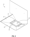
FIG.6 illustrates a perspective view of a hopper bottom assembly with horizontal surfaces surrounding a pellet opening; -
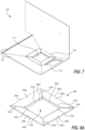
FIG.7 illustrates a perspective view of a hopper evacuation insert positioned within a hopper bottom assembly:-
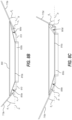
FIG. 8A illustrates a perspective view of a hopper evacuation insert according to an embodiment of the present invention;FIG. 8B illustrates a front view of a hopper evacuation insert according to an embodiment of the present invention: -
FIG.8C illustrates a rear view of a hopper evacuation insert according to an embodiment of the present invention;
-
- The present invention relates generally to systems, methods, and devices for grilling and warming food products. In particular, implementations of the present invention relate to self-cleaning pellet grills. For example, one or more embodiments of the present invention include a hopper bottom which has a first bottom panel connected to a second bottom panel at a first interface and connected to a third bottom panel at a second interface. The first, second and third innermost edges of each of the three respective bottom panels at least partially define a pellet evacuation opening. Each of the three bottom panels respectively form first, second and third nonzero angles with respect to a horizontal plane such that each bottom panel tilts downwards towards the pellet evacuation opening.
- The hopper with smooth pellet drop of the present invention includes features that increase the evacuation efficiency of the hopper, thus reducing the incidence of pellet evacuation failure. The embodiments disclosed herein, where implemented, may reduce the frequency of temperature loss during the processes of grilling and warming food products. Users are therefore able to use pellet grills without scrupulously overseeing the evacuation status of the pellet fuel into the auger system. Users are also more able to avoid the need to restart the grilling and/or warming process in response to a failed pellet evacuation. Additionally, in some instances, the aforementioned benefits are available to existing pellet grills via after-market modification, as described below.
-
FIGS. 2A-2C illustrate various views of a hopper bottom embodiment according to the present invention. In the embodiment shown, the hopper bottom includes bottom panels, or surfaces, which at least partially surround a pellet evacuation opening. In some instances, the pellet evacuation opening is positioned over an auger system, which receives fuel pellets from the hopper bottom as they exit the hopper bottom. - The bottom panels extend from the pellet evacuation opening to a predetermined perimeter. At the perimeter, the bottom panels are adapted to adjoin sidewalls. For example, as shown, one of the bottom panels is integrally formed with a sidewall. Other adjoining methods are also within the scope of this invention (such as welding, liquid or strip adhesives, etc.) Similarly, each of the bottom panels are configured to adjoin one another. In the illustrated embodiment, each of the bottom panels are integrally formed with one another (i.e., the hopper bottom is formed by folding a single sheet of material).
- The hopper bottom may adjoin a wall proximate to a grill cavity. In the illustrated embodiment, two of the bottom panels on opposite sides of the pellet evacuation opening are adapted to adjoin a wall proximate to a grill cavity. The pellet evacuation opening is also positioned such that the wall proximate to the grill cavity will define one side of the pellet evacuation opening. In some instances, this configuration optimizes the distance that the auger system positioned underneath the pellet evacuation opening will need to transport the pellets before they reach the firepot within the grill cavity.
- Existing designs for pellet grill hopper bottoms typically include horizontal surfaces which at least partially form the bottom panels and surround the pellet evacuation opening(see
FIG. 8B and 8C ). Hopper bottoms often require such horizontal surfaces in order to effectuate a water seal (e.g., by placing a gasket between parallel surfaces of the hopper bottom and the auger system) to prevent water from entering the auger system, since water can cause fuel pellets to stick to one another and can thereby prevent pellet evacuation. The horizontal surfaces, however, can also cause fuel pellets to come to rest rather than drop into the auger system. This results in reduced evacuation efficiency and/or total disruption of the grilling process (e.g., where pellets become clogged in the hopper bottom). - As demonstrated in
FIG. 2A , the hopper bottom includes no horizontal surfaces surrounding the pellet evacuation opening, with the exception of the auxiliary evacuation opening, which is situated some distance from the pellet evacuation opening. Put differently, for each bottom panel, the angle between surface and a horizontal axis is substantially constant throughout the length of each bottom panel between the pellet evacuation opening and the perimeter of the hopper bottom (with the exception of the auxiliary evacuation opening). - The displayed configuration, in some instances, prevents pellets from coming to rest before reaching the auger system. Additionally or alternatively, this configuration prevents the fuel pellets from becoming clogged in the hopper, and therefore prevents disruption of the cooking/grilling process.
-
Figures 2B and 2C display, respectively, front and right views of the hopper bottom according toFIG. 2A . As is evident from these figures, the bottom panels make different angles with the horizontal (48.77°, 25.46°, and 25°). It should be noted that those skilled in the art will recognize that other angles may be utilized in other embodiments of the hopper bottom (e.g., the angle for each panel could be the same). The angles may be selected based on certain criteria, including, but not limited to, resultant pellet capacity, pellet evacuation efficiency, number of bottom panels to be used, coating to be used with the bottom panels, and other criteria. - Although the pellet evacuation opening displayed in
FIGS. 2A-2C is surrounded by only 3 bottom panels, those skilled in the art will recognize that the pellet evacuation opening could be surround by any number of bottom panels comprising the hopper bottom. Additionally, those skilled in the art will recognize that the pellet evacuation opening may take any position with respect to the bottom panels (e.g., positioned so as to not adjoin a sidewall), and may be of any appropriate shape and size. -
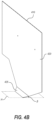
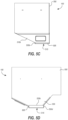
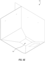
FIGS. 4A-4B illustrate various views of a hopper bottom assembly, wherein the hopper bottom ofFIGS. 2A-2C is connected with a wall panel proximate to a grill cavity and a shelf plate. It should be noted that any acceptable connection method may be used in creating the assembly depicted (e.g., welding or integrally forming all parts with each other). - In implementations where the hopper assembly is modular and separable from the rest of the pellet grilling system, a manufacturer or assembly may need to ensure that the interface between the hopper bottom and the auger system is configurable to prevent external contaminants from entering the grilling system (e.g., water). For example, the wall panel and shelf plate which are part of the hopper bottom assembly illustrated in
FIGS. 5A-5D include bottom horizontal surfaces which are separate from the bottom panels of the hopper bottom described above, and therefore do not immediately surround the interior of the pellet evacuation opening. This allows a gasket to be used between the hopper bottom assembly and the auger system to effectuate a water seal (seeFIG. 5A ). As illustrated inFIGS. 5A-5B , the wall panel to which the hopper bottom connects includes a bottom angled surface and a bottom horizontal surface. The bottom angled surface is beneficial to prevent clogging of the pellets as they evacuate from the hopper, since a horizontal surface by itself at the bottom of the wall panel would pose the same problems as described with respect to the bottom panels of the hopper bottom. - Situated underneath the bottom angled surface is a bottom horizontal surface (see
FIG. 5A-5D ), which provides, in conjunction with the shelf plate described below, a substantially planar surface upon which a gasket may be placed to form a water seal between the hopper bottom assembly and the auger system. - While the embodiment illustrated in
FIGS. 5A-5D is described as being configured to be usable with a gasket seal, it should be noted that those skilled in the art would recognize that other sealing methods are usable with the embodiments of the present invention (e.g., caulk, welding, and/or adhesive seals). It should also be noted that in some instances, a wall panel is used without an angled bottom surface (e.g., where the wall panel is integrally formed with the auger system and/or grill cavity so as to not require a gasket connection underneath the wall panel). -
FIG. 5B illustrates the shelf plate connected to the underside of the hopper bottom.
As noted above, the bottom panels of the hopper bottom do not include horizontal surfaces surrounding or near the pellet evacuation opening. In implementations where such horizontal surfaces are needed to effectuate a water seal, the shelf plate connects to the underside of the hopper bottom such that the three-sided horizontal surface of the shelf plate is substantially parallel to other horizontal surfaces to be used in effecting the water seal (e.g., the bottom horizontal surface of the wall panel and the corresponding horizontal surface(s) of the auger system). In the illustrated embodiment, the three-sided horizontal surface of the shelf plate are positioned adjacent to the bottom horizontal surface of the wall panel, such that a rectangular gasket is usable with the assembly shown. - Those skilled in the art will understand that the particular dimensions and/or shape of the elements of the embodiment shown in
Figures 2A-2C and5A-5D are illustrative and do not necessarily limit the scope of the invention at hand.Figures 3A-3C demonstrate the versatility of the present invention by illustrating an embodiment of a hopper bottom adapted to function with different pellet grill geometry. In particular, the hopper bottom embodiment depicted inFigures 3A-3C is adapted to abut a wall panel proximate to a grill cavity which is itself slanted. Additionally, the bottom panels of the depicted hopper bottom embodiment make different angles with the horizontal when compared with the embodiment shown inFigures 2A-2C and5A-5D (i.e., 17.31°, 16.69°, and 24.56°). The hopper bottom shown inFigures 3A-3C is similarly connectable to a shelf plate in order to form a water seal at an interface between the hopper bottom and an auger system. - Many users own pellet grills which include hoppers with bottom panels that comprise horizontal surfaces that surround the pellet evacuation opening. In many instances, the horizontal surfaces cause the pellets to come to rest before successfully evacuating from the hopper, which disrupts the grilling process. The benefits of the present invention (e.g., increased pellet evacuation efficiency and decreased incidence of pellet clogging) may be implemented into such existing pellet grills, as described below.
-
Figures 7 and8A-8C show an embodiment of a hopper evacuation insert which may be utilized with an existing hopper to ameliorate the problems associated with bottom panels that include horizontal surfaces near or surrounding a pellet evacuation opening. The hopper evacuation insert shown has four angled trapezoidal surfaces. In many instances, the number of angled trapezoidal surfaces corresponds to the number of bottom panels included in the hopper bottom of the existing pellet grill. Furthermore, in some instances, the angles of the trapezoidal surfaces correspond to the angles that the bottom panels of the hopper bottom make with a horizontal axis. In some instances, however, the angles of the trapezoidal surfaces are greater or lesser than the angles of the bottom panels of the hopper bottom of the existing pellet grill. In the illustrated embodiment, the trapezoidal surfaces have angles that are less than the corresponding bottom panels of the hopper bottom shown inFIG. 7 (21.40°, 14.19°, 15.86°, and 30.62°). - The hopper evacuation insert embodiment depicted in
Figures 7 and8A-8C also includes a vertical border, which extends downward from the innermost sides of the trapezoidal surfaces. Without the vertical border, placing the trapezoidal surfaces on the hopper bottom may form a groove between the innermost borders of the trapezoidal surfaces and the horizontal surfaces of the hopper bottom. Such a groove could cause the edges of the fuel pellets to become lodged within the groove, causing clogging of the fuel pellets. The vertical border prevents exposure of this groove, and thus helps to safeguard pellet evacuation efficiency. The vertical border may also serve to increase the stability of the hopper evacuation insert when placed in the existing hopper bottom. - In alternative embodiments, however, the trapezoidal surfaces of the hopper evacuation insert are adapted to continue directly from the respective edges/portions of the existing hopper bottom panels to the innermost boundaries of the horizontal surfaces that surround the pellet evacuation opening. In such embodiments, no groove is formed. Accordingly, in some embodiments, there is no need for a vertical border as described above.
- The hopper evacuation insert is adapted to be inserted into an existing hopper bottom, as demonstrated in
FIG. 7-8C . As illustrated, the hopper evacuation insert is positioned so as to cover the horizontal surfaces of the hopper bottom, which surround the pellet evacuation opening. This provides the fuel pellets with a slanted path towards the pellet evacuation opening throughout the entirety of the hopper bottom, removing the possibility of the pellets coming to rest on a horizontal surface.
Utilizing the hopper evacuation insert as illustrated inFIG. 7-8C does not compromise the functionality of the existing horizontal surfaces of the hopper bottom (i.e., they may still be used in a sealing system between the hopper bottom and the auger system). - The hopper evacuation insert may be applied to the existing hopper bottom through a variety of means. For example, users may use caulk, welding, adhesive strips, or other appropriate adhesion materials or methods to affix the hopper evacuation insert to the existing hopper bottom.
The hopper bottom embodiments and hopper evacuation insert embodiments as described herein operate to increase the pellet evacuation efficiency of pellet grills. For example, pellet evacuation efficiency of 88.49% has been achieved when utilizing the embodiments described inFigures 2A-2C and5A-5D . Pellet evacuation efficiency of greater than 95% is readily achievable when utilizing the embodiments expressed inFigures 5A-8C . Alternative embodiments have the potential of achieving even greater pellet evacuation efficiency. Accordingly, the embodiments disclosed herein allow for increased evacuation efficiency and a reduction in the incidence of pellet evacuation failure. - The present invention can be embodied in other specific forms without departing from its essential characteristics. The described embodiments are to be considered in all respects only as illustrative and not restrictive. The scope of the invention is, therefore, indicated by the appended claims rather than by the foregoing description. All changes that come within the meaning of the claims are to be embraced within their scope.
Claims (5)
- A pellet hopper assembly (100, 400), comprising:
a hopper bottom, comprising:
a first panel (405a) connected to a second panel (405b) at a first interface (210a) and the second panel (405b) connected to a third panel (405c) at a second interface (210b), wherein a first inner edge (215a) of the first panel (405a), a second inner edge (215b) of the second panel (405b), and a third inner edge (215c) of the third panel (405c) together define a pellet evacuation opening (435), and wherein:the first panel (405a) forms a first nonzero angle (θ1) with respect to a horizontal plane (H) such that the first panel (405a) tilts downward toward the pellet evacuation opening (435), the second panel (405b) forms a second nonzero angle (θ2) with respect to the horizontal plane (H) such that the second panel (405b) tilts downward toward the pellet evacuation opening (435); andthe third panel (405c) forms a third nonzero angle (θ3) with respect to the horizontal plane (H) such that the third panel (405c) tilts downward toward the pellet evacuation opening (435); anda wall panel (410) connected to the first and third panels (405a, 405c) at third and fourth interfaces (415a, 415b), respectively, the wall panel (410) comprising:a main surface (420) extending vertically upward from the third and fourth interfaces (415a, 415b); anda bottom angled surface (425) connected to the main surface (420), the bottom angled surface (425) including a fourth inner edge (430) that at least partially defines the pellet evacuation opening (435), the bottom angled surface (420) forming a fourth nonzero angle (β) with respect to the horizontal plane (H) such that the bottom angled surface (425) tilts downward toward the pellet evacuation opening (435). - The pellet hopper assembly (400) of claim 1, further comprising a pellet evacuation insert (800), the pellet evacuation insert (800) comprising:a first insert panel (805a) connected to a second insert panel (805b) at a first interface (810a); anda third insert panel (805c) connected to the second insert panel (805b) at a second interface (810b); wherein:the first, second, and third insert panels (805a, 805b, 805c) have first, second, and third inner edges (815a, 815b, 815c) that at least partially define a pellet evacuation insert opening (820);the first, second, and third insert panels are angled at respective first, second, and third nonzero angles (µ1, µ2, µ3) with respect to the horizontal plane (H) such that the first, second, and third insert panels (805a, 805b, 805c) of the pellet evacuation insert (800) tilt downward toward the pellet evacuation insert opening (820); andeach of the first, second, and third insert panels (805a, 805b, 805c) include an outer edge (825a, 825b, 825c) that contacts a top surface of each of the first, second, and third panels (405a, 405b, 405c) of the hopper bottom, respectively.
- The pellet hopper assembly (100, 400) of claim 2, wherein the pellet evacuation insert (800) further comprises a fourth insert panel (805d) having a fourth inner edge (815d) that at least partially defines the pellet evacuation insert opening (820), the fourth insert panel (800) being angled at a nonzero angle (µ4) with respect to the horizontal plane (H) so that the fourth insert panel (805d) of the pellet evacuation insert (800) tilts downward toward the pellet evacuation insert opening (820).
- The pellet hopper assembly of claim 3, wherein the first, second, third, and fourth insert panels (805a, 805b, 805c, 805d) are planar trapezoid so as to form a rectangular pellet evacuation insert opening (820).
- The pellet hopper assembly of one of claims 2 to 4, wherein the pellet evacuation insert (800) further comprises first, second, and third vertical walls (830a, 830b, 830c) extending downward from the first, second, and third inner edges (815a, 815b, 815c), respectively.
Applications Claiming Priority (2)
| Application Number | Priority Date | Filing Date | Title |
|---|---|---|---|
| US201862670960P | 2018-05-14 | 2018-05-14 | |
| PCT/US2019/032211 WO2019222209A1 (en) | 2018-05-14 | 2019-05-14 | Pellet hopper liner |
Publications (3)
| Publication Number | Publication Date |
|---|---|
| EP3794281A1 EP3794281A1 (en) | 2021-03-24 |
| EP3794281B1 true EP3794281B1 (en) | 2024-08-07 |
| EP3794281C0 EP3794281C0 (en) | 2024-08-07 |
Family
ID=66669133
Family Applications (1)
| Application Number | Title | Priority Date | Filing Date |
|---|---|---|---|
| EP19727248.7A Active EP3794281B1 (en) | 2018-05-14 | 2019-05-14 | Pellet hopper liner |
Country Status (4)
| Country | Link |
|---|---|
| EP (1) | EP3794281B1 (en) |
| CN (1) | CN112136004A (en) |
| CA (1) | CA3098877A1 (en) |
| WO (1) | WO2019222209A1 (en) |
Families Citing this family (6)
| Publication number | Priority date | Publication date | Assignee | Title |
|---|---|---|---|---|
| EP3969811B1 (en) * | 2019-05-14 | 2025-01-08 | Traeger Pellet Grills, LLC | Pellet hopper assembly |
| US12446730B2 (en) | 2022-03-29 | 2025-10-21 | Sharkninja Operating Llc | Grill system with smoke assembly |
| US12478213B2 (en) | 2022-03-29 | 2025-11-25 | Sharkninja Operating Llc | Grill system with smoke assembly |
| US12070042B2 (en) | 2022-12-12 | 2024-08-27 | Sharkninja Operating Llc | Grill systems |
| US12035725B2 (en) | 2022-12-12 | 2024-07-16 | Sharkninja Operating, Llc | Grill systems |
| USD1063483S1 (en) | 2023-06-15 | 2025-02-25 | Sharkninja Operating Llc | Cooking device |
Family Cites Families (17)
| Publication number | Priority date | Publication date | Assignee | Title |
|---|---|---|---|---|
| GB1019612A (en) * | 1962-09-25 | 1966-02-09 | John Lawrence Margetts | Improvements relating to coal-fired heating units |
| EP0196105A3 (en) * | 1985-03-29 | 1988-03-30 | ULS International Inc. | Method and apparatus for handling particulate material |
| AU699507B2 (en) * | 1995-05-06 | 1998-12-03 | Lyndon Bates | Bulk storage hoppers |
| US6109478A (en) * | 1997-10-24 | 2000-08-29 | Eskom | Conveying of materials |
| JP3480914B2 (en) * | 1999-06-29 | 2003-12-22 | 不動建設株式会社 | Sand and sand-like granular material introduction device |
| AU2007202103B2 (en) * | 2006-05-11 | 2011-05-26 | Trelleborg Engineered Products Australia Pty Ltd | Flexible liner for hoppers or chutes |
| US20110155027A1 (en) * | 2009-12-29 | 2011-06-30 | Clarence Waldner | Auger for transporting particulate material with a reduced tendency to block |
| JP5535819B2 (en) * | 2010-08-10 | 2014-07-02 | 株式会社山本製作所 | Wood pellet combustion equipment |
| CN102379636A (en) * | 2011-09-22 | 2012-03-21 | 陈永辉 | Electric and pellet fuel hybrid heating grill |
| US20140326233A1 (en) * | 2013-05-02 | 2014-11-06 | Joe Traeger | Dc pellet burner assembly |
| CN104291034A (en) * | 2013-07-17 | 2015-01-21 | 湖北叶威粮油机械有限公司 | Novel material collecting hopper |
| US9441838B2 (en) * | 2013-11-18 | 2016-09-13 | Edward Baker | Pellet bin insert and storage system for smoker grills |
| KR101515001B1 (en) * | 2014-03-31 | 2015-05-04 | 임재욱 | Pellet stove |
| US10213051B2 (en) * | 2015-09-09 | 2019-02-26 | Traeger Pellet Grills, Llc | Oval-shaped grill with hinged lid |
| CN106553847A (en) * | 2015-09-30 | 2017-04-05 | 扬州通和机械有限公司 | A kind of new high-efficiency discharging hopper |
| KR101627991B1 (en) * | 2016-01-04 | 2016-06-07 | 박현조 | Wood pellet burner for a pottery kiln |
| KR200486674Y1 (en) * | 2017-05-23 | 2018-06-19 | 김성두 | Stove |
-
2019
- 2019-05-14 CA CA3098877A patent/CA3098877A1/en not_active Abandoned
- 2019-05-14 EP EP19727248.7A patent/EP3794281B1/en active Active
- 2019-05-14 CN CN201980032317.4A patent/CN112136004A/en active Pending
- 2019-05-14 WO PCT/US2019/032211 patent/WO2019222209A1/en not_active Ceased
Also Published As
| Publication number | Publication date |
|---|---|
| CN112136004A (en) | 2020-12-25 |
| WO2019222209A1 (en) | 2019-11-21 |
| EP3794281A1 (en) | 2021-03-24 |
| CA3098877A1 (en) | 2019-11-21 |
| EP3794281C0 (en) | 2024-08-07 |
Similar Documents
| Publication | Publication Date | Title |
|---|---|---|
| WO2019222209A1 (en) | Pellet hopper liner | |
| US11162684B2 (en) | Pellet hopper liner | |
| EP2977684B1 (en) | Oven | |
| EP3969811B1 (en) | Pellet hopper assembly | |
| US11841146B2 (en) | Multifunctional appliance for cooking | |
| JP6235709B2 (en) | Vacuum drawer for food vacuum packaging with operable lid | |
| US9388990B2 (en) | Metal panel, manufacturing method thereof and cooking device using the metal panel | |
| USD963889S1 (en) | Indoor wall with built-in home appliances | |
| EP2108294B1 (en) | Lifting-cover type frying-roasting device | |
| US4640265A (en) | Insert for converting a conventional home oven into a pizza oven | |
| CN107205564A (en) | heating cooker | |
| EP3572351A1 (en) | Microwave oven container | |
| US11708975B2 (en) | Pellet hopper liner | |
| JP4148923B2 (en) | Glass top plate for stove | |
| JP6945142B2 (en) | Pressure type rice cooker | |
| JP2004338940A (en) | Elevator shaft closing device, method for fulfilling fire protection requirements of elevator shaft closing device and its installation method | |
| JP6576282B2 (en) | post | |
| JP7053989B2 (en) | Toaster oven | |
| EP2329199B1 (en) | An oven with cooking chamber | |
| KR101770410B1 (en) | Packaging bag for microwave oven | |
| JP2000130770A (en) | Cooking tray and cooking appliance | |
| US20130162129A1 (en) | Partition adapted for separating a cooktop from a underlying drawer | |
| KR200482488Y1 (en) | assembled box Prevented | |
| CN219578773U (en) | Material box, material box opening device and cooking equipment | |
| CN216221214U (en) | Cooking apparatus |
Legal Events
| Date | Code | Title | Description |
|---|---|---|---|
| STAA | Information on the status of an ep patent application or granted ep patent |
Free format text: STATUS: THE INTERNATIONAL PUBLICATION HAS BEEN MADE |
|
| PUAI | Public reference made under article 153(3) epc to a published international application that has entered the european phase |
Free format text: ORIGINAL CODE: 0009012 |
|
| STAA | Information on the status of an ep patent application or granted ep patent |
Free format text: STATUS: REQUEST FOR EXAMINATION WAS MADE |
|
| 17P | Request for examination filed |
Effective date: 20201204 |
|
| AK | Designated contracting states |
Kind code of ref document: A1 Designated state(s): AL AT BE BG CH CY CZ DE DK EE ES FI FR GB GR HR HU IE IS IT LI LT LU LV MC MK MT NL NO PL PT RO RS SE SI SK SM TR |
|
| AX | Request for extension of the european patent |
Extension state: BA ME |
|
| RIN1 | Information on inventor provided before grant (corrected) |
Inventor name: COLSTON, MICHAEL Inventor name: SLUDER, DANIEL Inventor name: HOANG, PHUONG |
|
| DAV | Request for validation of the european patent (deleted) | ||
| DAX | Request for extension of the european patent (deleted) | ||
| STAA | Information on the status of an ep patent application or granted ep patent |
Free format text: STATUS: EXAMINATION IS IN PROGRESS |
|
| 17Q | First examination report despatched |
Effective date: 20221121 |
|
| GRAP | Despatch of communication of intention to grant a patent |
Free format text: ORIGINAL CODE: EPIDOSNIGR1 |
|
| STAA | Information on the status of an ep patent application or granted ep patent |
Free format text: STATUS: GRANT OF PATENT IS INTENDED |
|
| INTG | Intention to grant announced |
Effective date: 20240404 |
|
| GRAS | Grant fee paid |
Free format text: ORIGINAL CODE: EPIDOSNIGR3 |
|
| GRAA | (expected) grant |
Free format text: ORIGINAL CODE: 0009210 |
|
| STAA | Information on the status of an ep patent application or granted ep patent |
Free format text: STATUS: THE PATENT HAS BEEN GRANTED |
|
| AK | Designated contracting states |
Kind code of ref document: B1 Designated state(s): AL AT BE BG CH CY CZ DE DK EE ES FI FR GB GR HR HU IE IS IT LI LT LU LV MC MK MT NL NO PL PT RO RS SE SI SK SM TR |
|
| REG | Reference to a national code |
Ref country code: GB Ref legal event code: FG4D |
|
| REG | Reference to a national code |
Ref country code: CH Ref legal event code: EP |
|
| REG | Reference to a national code |
Ref country code: IE Ref legal event code: FG4D |
|
| REG | Reference to a national code |
Ref country code: DE Ref legal event code: R096 Ref document number: 602019056545 Country of ref document: DE |
|
| U01 | Request for unitary effect filed |
Effective date: 20240807 |
|
| U07 | Unitary effect registered |
Designated state(s): AT BE BG DE DK EE FI FR IT LT LU LV MT NL PT SE SI Effective date: 20240823 |
|
| PG25 | Lapsed in a contracting state [announced via postgrant information from national office to epo] |
Ref country code: NO Free format text: LAPSE BECAUSE OF FAILURE TO SUBMIT A TRANSLATION OF THE DESCRIPTION OR TO PAY THE FEE WITHIN THE PRESCRIBED TIME-LIMIT Effective date: 20241107 |
|
| PG25 | Lapsed in a contracting state [announced via postgrant information from national office to epo] |
Ref country code: PL Free format text: LAPSE BECAUSE OF FAILURE TO SUBMIT A TRANSLATION OF THE DESCRIPTION OR TO PAY THE FEE WITHIN THE PRESCRIBED TIME-LIMIT Effective date: 20240807 Ref country code: GR Free format text: LAPSE BECAUSE OF FAILURE TO SUBMIT A TRANSLATION OF THE DESCRIPTION OR TO PAY THE FEE WITHIN THE PRESCRIBED TIME-LIMIT Effective date: 20241108 |
|
| PG25 | Lapsed in a contracting state [announced via postgrant information from national office to epo] |
Ref country code: IS Free format text: LAPSE BECAUSE OF FAILURE TO SUBMIT A TRANSLATION OF THE DESCRIPTION OR TO PAY THE FEE WITHIN THE PRESCRIBED TIME-LIMIT Effective date: 20241207 |
|
| PG25 | Lapsed in a contracting state [announced via postgrant information from national office to epo] |
Ref country code: HR Free format text: LAPSE BECAUSE OF FAILURE TO SUBMIT A TRANSLATION OF THE DESCRIPTION OR TO PAY THE FEE WITHIN THE PRESCRIBED TIME-LIMIT Effective date: 20240807 |
|
| PG25 | Lapsed in a contracting state [announced via postgrant information from national office to epo] |
Ref country code: ES Free format text: LAPSE BECAUSE OF FAILURE TO SUBMIT A TRANSLATION OF THE DESCRIPTION OR TO PAY THE FEE WITHIN THE PRESCRIBED TIME-LIMIT Effective date: 20240807 Ref country code: RS Free format text: LAPSE BECAUSE OF FAILURE TO SUBMIT A TRANSLATION OF THE DESCRIPTION OR TO PAY THE FEE WITHIN THE PRESCRIBED TIME-LIMIT Effective date: 20241107 |
|
| PG25 | Lapsed in a contracting state [announced via postgrant information from national office to epo] |
Ref country code: RS Free format text: LAPSE BECAUSE OF FAILURE TO SUBMIT A TRANSLATION OF THE DESCRIPTION OR TO PAY THE FEE WITHIN THE PRESCRIBED TIME-LIMIT Effective date: 20241107 Ref country code: PL Free format text: LAPSE BECAUSE OF FAILURE TO SUBMIT A TRANSLATION OF THE DESCRIPTION OR TO PAY THE FEE WITHIN THE PRESCRIBED TIME-LIMIT Effective date: 20240807 Ref country code: NO Free format text: LAPSE BECAUSE OF FAILURE TO SUBMIT A TRANSLATION OF THE DESCRIPTION OR TO PAY THE FEE WITHIN THE PRESCRIBED TIME-LIMIT Effective date: 20241107 Ref country code: IS Free format text: LAPSE BECAUSE OF FAILURE TO SUBMIT A TRANSLATION OF THE DESCRIPTION OR TO PAY THE FEE WITHIN THE PRESCRIBED TIME-LIMIT Effective date: 20241207 Ref country code: HR Free format text: LAPSE BECAUSE OF FAILURE TO SUBMIT A TRANSLATION OF THE DESCRIPTION OR TO PAY THE FEE WITHIN THE PRESCRIBED TIME-LIMIT Effective date: 20240807 Ref country code: GR Free format text: LAPSE BECAUSE OF FAILURE TO SUBMIT A TRANSLATION OF THE DESCRIPTION OR TO PAY THE FEE WITHIN THE PRESCRIBED TIME-LIMIT Effective date: 20241108 Ref country code: ES Free format text: LAPSE BECAUSE OF FAILURE TO SUBMIT A TRANSLATION OF THE DESCRIPTION OR TO PAY THE FEE WITHIN THE PRESCRIBED TIME-LIMIT Effective date: 20240807 |
|
| PG25 | Lapsed in a contracting state [announced via postgrant information from national office to epo] |
Ref country code: SM Free format text: LAPSE BECAUSE OF FAILURE TO SUBMIT A TRANSLATION OF THE DESCRIPTION OR TO PAY THE FEE WITHIN THE PRESCRIBED TIME-LIMIT Effective date: 20240807 |
|
| PG25 | Lapsed in a contracting state [announced via postgrant information from national office to epo] |
Ref country code: CZ Free format text: LAPSE BECAUSE OF FAILURE TO SUBMIT A TRANSLATION OF THE DESCRIPTION OR TO PAY THE FEE WITHIN THE PRESCRIBED TIME-LIMIT Effective date: 20240807 |
|
| PG25 | Lapsed in a contracting state [announced via postgrant information from national office to epo] |
Ref country code: SK Free format text: LAPSE BECAUSE OF FAILURE TO SUBMIT A TRANSLATION OF THE DESCRIPTION OR TO PAY THE FEE WITHIN THE PRESCRIBED TIME-LIMIT Effective date: 20240807 |
|
| RAP4 | Party data changed (patent owner data changed or rights of a patent transferred) |
Owner name: TRAEGER PELLET GRILLS, LLC |
|
| U1H | Name or address of the proprietor changed after the registration of the unitary effect |
Owner name: TRAEGER PELLET GRILLS, LLC; US |
|
| PLBE | No opposition filed within time limit |
Free format text: ORIGINAL CODE: 0009261 |
|
| STAA | Information on the status of an ep patent application or granted ep patent |
Free format text: STATUS: NO OPPOSITION FILED WITHIN TIME LIMIT |
|
| U20 | Renewal fee for the european patent with unitary effect paid |
Year of fee payment: 7 Effective date: 20250527 |
|
| PGFP | Annual fee paid to national office [announced via postgrant information from national office to epo] |
Ref country code: GB Payment date: 20250527 Year of fee payment: 7 |
|
| 26N | No opposition filed |
Effective date: 20250508 |
|
| REG | Reference to a national code |
Ref country code: CH Ref legal event code: H13 Free format text: ST27 STATUS EVENT CODE: U-0-0-H10-H13 (AS PROVIDED BY THE NATIONAL OFFICE) Effective date: 20251223 |
|
| PG25 | Lapsed in a contracting state [announced via postgrant information from national office to epo] |
Ref country code: CH Free format text: LAPSE BECAUSE OF NON-PAYMENT OF DUE FEES Effective date: 20250531 |
|
| PG25 | Lapsed in a contracting state [announced via postgrant information from national office to epo] |
Ref country code: MC Free format text: LAPSE BECAUSE OF FAILURE TO SUBMIT A TRANSLATION OF THE DESCRIPTION OR TO PAY THE FEE WITHIN THE PRESCRIBED TIME-LIMIT Effective date: 20240807 |
|
| PG25 | Lapsed in a contracting state [announced via postgrant information from national office to epo] |
Ref country code: IE Free format text: LAPSE BECAUSE OF NON-PAYMENT OF DUE FEES Effective date: 20250514 |
|
| PG25 | Lapsed in a contracting state [announced via postgrant information from national office to epo] |
Ref country code: RO Free format text: LAPSE BECAUSE OF FAILURE TO SUBMIT A TRANSLATION OF THE DESCRIPTION OR TO PAY THE FEE WITHIN THE PRESCRIBED TIME-LIMIT Effective date: 20240807 |