EP3794240B1 - Bolt and fastening structure - Google Patents
Bolt and fastening structure Download PDFInfo
- Publication number
- EP3794240B1 EP3794240B1 EP19726174.6A EP19726174A EP3794240B1 EP 3794240 B1 EP3794240 B1 EP 3794240B1 EP 19726174 A EP19726174 A EP 19726174A EP 3794240 B1 EP3794240 B1 EP 3794240B1
- Authority
- EP
- European Patent Office
- Prior art keywords
- thread
- bolt
- female screw
- threads
- shaft
- Prior art date
- Legal status (The legal status is an assumption and is not a legal conclusion. Google has not performed a legal analysis and makes no representation as to the accuracy of the status listed.)
- Active
Links
Images


Classifications
-
- F—MECHANICAL ENGINEERING; LIGHTING; HEATING; WEAPONS; BLASTING
- F16—ENGINEERING ELEMENTS AND UNITS; GENERAL MEASURES FOR PRODUCING AND MAINTAINING EFFECTIVE FUNCTIONING OF MACHINES OR INSTALLATIONS; THERMAL INSULATION IN GENERAL
- F16B—DEVICES FOR FASTENING OR SECURING CONSTRUCTIONAL ELEMENTS OR MACHINE PARTS TOGETHER, e.g. NAILS, BOLTS, CIRCLIPS, CLAMPS, CLIPS OR WEDGES; JOINTS OR JOINTING
- F16B33/00—Features common to bolt and nut
- F16B33/02—Shape of thread; Special thread-forms
-
- F—MECHANICAL ENGINEERING; LIGHTING; HEATING; WEAPONS; BLASTING
- F16—ENGINEERING ELEMENTS AND UNITS; GENERAL MEASURES FOR PRODUCING AND MAINTAINING EFFECTIVE FUNCTIONING OF MACHINES OR INSTALLATIONS; THERMAL INSULATION IN GENERAL
- F16B—DEVICES FOR FASTENING OR SECURING CONSTRUCTIONAL ELEMENTS OR MACHINE PARTS TOGETHER, e.g. NAILS, BOLTS, CIRCLIPS, CLAMPS, CLIPS OR WEDGES; JOINTS OR JOINTING
- F16B35/00—Screw-bolts; Stay-bolts; Screw-threaded studs; Screws; Set screws
- F16B35/007—Removing paint or dirt layers covering the threaded part of nut-like members
-
- F—MECHANICAL ENGINEERING; LIGHTING; HEATING; WEAPONS; BLASTING
- F16—ENGINEERING ELEMENTS AND UNITS; GENERAL MEASURES FOR PRODUCING AND MAINTAINING EFFECTIVE FUNCTIONING OF MACHINES OR INSTALLATIONS; THERMAL INSULATION IN GENERAL
- F16B—DEVICES FOR FASTENING OR SECURING CONSTRUCTIONAL ELEMENTS OR MACHINE PARTS TOGETHER, e.g. NAILS, BOLTS, CIRCLIPS, CLAMPS, CLIPS OR WEDGES; JOINTS OR JOINTING
- F16B2200/00—Constructional details of connections not covered for in other groups of this subclass
- F16B2200/93—Fastener comprising feature for establishing a good electrical connection, e.g. electrostatic discharge or insulation feature
-
- F—MECHANICAL ENGINEERING; LIGHTING; HEATING; WEAPONS; BLASTING
- F16—ENGINEERING ELEMENTS AND UNITS; GENERAL MEASURES FOR PRODUCING AND MAINTAINING EFFECTIVE FUNCTIONING OF MACHINES OR INSTALLATIONS; THERMAL INSULATION IN GENERAL
- F16B—DEVICES FOR FASTENING OR SECURING CONSTRUCTIONAL ELEMENTS OR MACHINE PARTS TOGETHER, e.g. NAILS, BOLTS, CIRCLIPS, CLAMPS, CLIPS OR WEDGES; JOINTS OR JOINTING
- F16B33/00—Features common to bolt and nut
- F16B33/008—Corrosion preventing means
-
- F—MECHANICAL ENGINEERING; LIGHTING; HEATING; WEAPONS; BLASTING
- F16—ENGINEERING ELEMENTS AND UNITS; GENERAL MEASURES FOR PRODUCING AND MAINTAINING EFFECTIVE FUNCTIONING OF MACHINES OR INSTALLATIONS; THERMAL INSULATION IN GENERAL
- F16B—DEVICES FOR FASTENING OR SECURING CONSTRUCTIONAL ELEMENTS OR MACHINE PARTS TOGETHER, e.g. NAILS, BOLTS, CIRCLIPS, CLAMPS, CLIPS OR WEDGES; JOINTS OR JOINTING
- F16B33/00—Features common to bolt and nut
- F16B33/02—Shape of thread; Special thread-forms
- F16B33/04—Shape of thread; Special thread-forms in view of tensile load
-
- F—MECHANICAL ENGINEERING; LIGHTING; HEATING; WEAPONS; BLASTING
- F16—ENGINEERING ELEMENTS AND UNITS; GENERAL MEASURES FOR PRODUCING AND MAINTAINING EFFECTIVE FUNCTIONING OF MACHINES OR INSTALLATIONS; THERMAL INSULATION IN GENERAL
- F16B—DEVICES FOR FASTENING OR SECURING CONSTRUCTIONAL ELEMENTS OR MACHINE PARTS TOGETHER, e.g. NAILS, BOLTS, CIRCLIPS, CLAMPS, CLIPS OR WEDGES; JOINTS OR JOINTING
- F16B39/00—Locking of screws, bolts or nuts
- F16B39/22—Locking of screws, bolts or nuts in which the locking takes place during screwing down or tightening
- F16B39/28—Locking of screws, bolts or nuts in which the locking takes place during screwing down or tightening by special members on, or shape of, the nut or bolt
- F16B39/30—Locking exclusively by special shape of the screw-thread
Definitions
- the present invention relates to a bolt and a fastening structure.
- Patent Literature 1 There is known a technique by which a coating film within a nut can be peeled off when a bolt is tightened, as described in Patent Literature 1.
- the bolt described in Patent Literature 1 is tapered and also axially grooved at a part on its tip end side.
- it is intended to peel off a coating film with a thread on the tapered tip end side.
- the thread on the tip end side and the coating film applied to a female screw do not come in contact with each other sufficiently, so that the coating film may not be peeled off sufficiently.
- a problem to be solved by the present invention is to threadedly engage a bolt and a female screw with each other, thereby making it possible to shave off a deposit on the inner surface of the female screw and to make it easy for a worker to sense the seating.
- the present invention provides a bolt according to claim 1.
- the thread provided larger in diameter than the first thread and the thread provided wider than the first thread are provided on the tip end side of the shaft.
- a thread having a friction coefficient stabilizer applied thereto is provided on the tip end side of the shaft.
- the bolt and the female screw are threadedly engaged with each other, thereby making it possible to shave off a deposit on the inner surface of the female screw and to make it easy for a worker to sense the seating.
- the bolt 1 of the embodiment includes a shaft 2 and a head 3, and a first thread 11 is provided on the head 3 side of the shaft 2.
- a thread provided larger in diameter than the first thread 11 and a thread provided wider than the first thread 11 is provided on the tip end side of the shaft 2. Therefore, the bolt 1 and a female screw 5 are threadedly engaged with each other, thereby making it possible to shave off a deposit on the inner surface of the female screw 5 and to make it easy for a worker to sense the seating.
- the bolt 1 shown in Figs. 1 and 2 is provided with the first thread 11 on the head 3 side of the shaft 2.
- the bolt 1 is provided with a second thread 12 larger in diameter than the first thread 11 and a third thread 13 wider than the first thread 11.
- the second thread 12 is provided larger in diameter than that of the third thread 13, and the third thread 13 is provided wider than the second thread 12.
- the first thread 11 is used for threaded engagement with the female screw 5 which is usually performed
- the second thread 12 and the third thread 13 are mainly used to peel off a deposit on the female screw 5.
- a radius Lb of the second thread 12 is formed larger than a radius La of the first thread 11. More specifically, the diameter of the first thread 11 is usually formed to be equal to the value defined by the nominal diameter, but the diameter of the second thread 12 is formed to be larger than the diameter of the first thread 11.
- the second thread 12 is different from the first thread 11 in terms of the contact position with the female screw 5, so that a gap between the male screw and the female screw 5 can be reduced.
- the radius Lb of the second thread 12 is formed smaller than the valley radius of the female screw 5.
- the radiuses of all the threads provided in the bolt 1 are smaller than the valley radius of the female screw 5, thereby making it possible to suppress an excessive load when the bolt 1 is tightened.
- a width Wb of the third thread 13 is wider than a width Wa of the first thread 11.
- the width Wb of the third thread 13 is wider than the width Wa of the first thread 11, for the entire flank.
- the third thread 13 can be made smaller than the first thread 11 in terms of the gap with the female screw 5, as understood from what is shown in Fig. 3 .
- the deposit on the inner surface of the female screw 5 can be shaved off more effectively.
- the female screw 5 is formed by applying a coating to a metallic female screw body.
- the width Wb of the third thread 13 of the bolt 1 is shorter than the distance between the flank surfaces of the adjacent threads in the female screw body at the position radially separated by the predetermined length Lc from the central axis C of the shaft 2. For this reason, it becomes possible to peel off the coating film, while suppressing the damage of the female screw body by the third thread 13.
- the first threads 11 which occupy a majority of the threads of the bolt 1 according to the embodiment are formed so as to be equal, in diameter and width, to general threads. Further, on the tip end side of the shaft 2 of the bolt 1 shown in Figs. 1 and 2 , there are provided two pitches of the larger-diameter threads which serve as the second threads 12 and two pitches of the wider threads which serve as the third threads 13.
- the numbers of pitches of the second threads 12 and the third threads 13 are not limited, but are preferably smaller than the number of pitches of the first threads 11. In the bolt 1 shown in Fig. 1 , the pitches of the first threads occupy more than half of the pitches of all the threads.
- the larger-diameter second threads 12 may be provided on the tip end side of the shaft 2 as compared with the wider third threads 13.
- the bolt 1 of the embodiment is provided with a notch 19 on the tip end side of the shaft 2.
- the notch 19 functions to positively remove the deposit adhering onto the female screw 5 and to discharge the removed deposit from the tip end side of the bolt 1.
- This notch 19 may be formed to extend in the same direction as the longitudinal direction of the shaft 2, but is preferably formed so that, in the side view, the angle ⁇ formed by the longitudinal direction of the notch 19 and the central axis C is 20 to 45° (see Fig. 1 ). Further, it is preferable to provide a plurality of notches 19. In the embodiment, three notches 19 are provided so as to be spaced in the circumferential direction. Preferably, no other notch 19 is arranged at a position shifted by 180 degrees in the circumferential direction of the shaft 2.
- the notch 19 preferably has a width Wc of about 1 to 3 mm.
- the length, in the longitudinal direction, of the notch 19 is preferably less than 50% of the nominal diameter of the bolt 1.
- a friction coefficient stabilizer is applied to the tip end side of the shaft 2 of the bolt 1.
- This friction coefficient stabilizer is intended for smooth threaded engagement with the female screw 5 such as a nut, and examples thereof include wax.
- the application of the friction coefficient stabilizer can suppress an increase in tightening load, for example, due to a reduction in the gap with the female screw 5.
- the friction coefficient stabilizer may or may not be applied to the first thread 11.
- the friction coefficient stabilizer may have any other function such as corrosion resistant function.
- the bolt 1 of the present invention when rotated, will be screwed into the nut while the coating film adhering onto the nut will be shaved off with the second thread 12 formed larger in diameter or the third thread 13 formed wider than the first thread 11. At this time, a screwing torque for screwing the second thread 12 or the third thread 13 into the nut is generated. However, when the nut goes over such a thread, the screwing torque is eliminated (see the solid line in Fig. 8 ). For this reason, the load on the worker when turning the bolt 1 or the nut is sufficiently reduced.
- the bolt 1 or the nut when further turned, will be seated, and further rotation thereof becomes difficult.
- the load when rotating the bolt 1 or the nut rapidly increases, whereby the worker can sense the seating. It is preferable that the nut in the seated state be in contact with the first thread 11 without being in contact with the second thread 12 or the third thread 13, but, if the nut is slightly contacted with the second thread 12 or the third thread 13, such contact may be permitted.
- the present invention has been described above using the embodiment, but is not limited to the embodiment described above, and various modes can be adopted, within the scope of the appended claims.
- the material for the bolt does not have to be iron, and may be another material.
- the bolt is preferably made of metal.
- the material to be peeled off by the bolt is not limited to the coating film, and may be sputtering or burrs.
- the counterpart into which the bolt is screwed does not have to be the nut, and may be a member provided with a female screw in advance.
- the numbers of pitches of the second threads and the third threads may be 1 or 2, or 3 or more. However, if the numbers of pitches of these threads increase, the tip of the bolt protruding from the female screw in the fastened state will be longer, and the bolt will be heavier. For this reason, when the bolt is used for vehicles such as a wheeled vehicle, it is preferable to set the numbers of pitches to about 3 or less.
Landscapes
- Engineering & Computer Science (AREA)
- General Engineering & Computer Science (AREA)
- Mechanical Engineering (AREA)
- Connection Of Plates (AREA)
- Bolts, Nuts, And Washers (AREA)
- Hand Tools For Fitting Together And Separating, Or Other Hand Tools (AREA)
Description
- The present invention relates to a bolt and a fastening structure.
- There is known a technique by which a coating film within a nut can be peeled off when a bolt is tightened, as described in
Patent Literature 1. The bolt described inPatent Literature 1 is tapered and also axially grooved at a part on its tip end side. In the technique described inPatent Literature 1, it is intended to peel off a coating film with a thread on the tapered tip end side. However, in such a form, the thread on the tip end side and the coating film applied to a female screw do not come in contact with each other sufficiently, so that the coating film may not be peeled off sufficiently. In order to solve this problem, it is also conceivable to shave off a counterpart member with a head-side portion formed thick as in the tapping screw described inPatent Literature 2. -
- [PTL1]
JP H5-340415 A - [PTL2]
JP 2014-37893 A - When a nut is tightened to a normal bolt, the tightening torque rapidly increases when the nut has been just seated, so that a worker can easily sense the seating. However, when a nut is tightened while a coating film or the like is removed with a thread on the head side, this is not the case because of a load involved in the removal. For this reason, there is a possibility that the worker cannot easily sense the seating.
- An example of a bolt of the prior art is shown in
US3351115A . - The present inventor made intensive studies to solve this problem. A problem to be solved by the present invention is to threadedly engage a bolt and a female screw with each other, thereby making it possible to shave off a deposit on the inner surface of the female screw and to make it easy for a worker to sense the seating.
- In order to solve the above problem, the present invention provides a bolt according to
claim 1. - Moreover, according to the invention, the thread provided larger in diameter than the first thread and the thread provided wider than the first thread are provided on the tip end side of the shaft.
- Moreover, it is preferable to employ a structure in which a thread provided with a notch is provided on the tip end side of the shaft.
- Moreover, it is preferable to employ a structure in which a thread having a friction coefficient stabilizer applied thereto is provided on the tip end side of the shaft.
- Moreover, it is preferable to provide a fastening structure in which the bolt described above and a female screw are threadedly engaged with each other for fastening.
- In the present invention, the bolt and the female screw are threadedly engaged with each other, thereby making it possible to shave off a deposit on the inner surface of the female screw and to make it easy for a worker to sense the seating.
-
- [
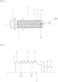
fig.1]Fig. 1 is a side view of a bolt according to an embodiment. - [
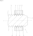
fig.2]Fig. 2 is a diagram showing the width of first threads and the width of third threads at a position radially separated by a predetermined length from a central axis of the bolt. However, the diameter of the first threads and the diameter of second threads are also shown. - [
fig.3]Fig. 3 is a conceptual diagram showing a gap formed between the respective first threads and a female screw, a gap generated between the respective second threads and the female screw, and a gap generated between the respective third threads and the female screw. However, the first threads, the second threads, and the third threads are sequentially provided from the head toward the tip end side of the shaft. - [
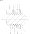
fig.4]Fig. 4 is a diagram showing an example in which the female screw is attached onto a bolt in which the first threads, the third threads and the second threads are sequentially provided from the head toward the tip end side of the shaft. - [
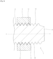
fig.5]Fig. 5 is a diagram showing a not claimed example in which the female screw is attached onto a bolt in which the first threads and the second threads are sequentially provided from the head toward the tip end side of the shaft. - [
fig.6]Fig. 6 is a diagram showing a not claimed example in which the female screw is attached onto a bolt in which the first threads and the third threads are sequentially provided from the head toward the tip end side of the shaft. - [
fig.7]Fig. 7 is a diagram showing a state in which members are fastened by the bolt shown inFig. 1 and a nut. - [
fig.8]Fig. 8 shows the relationship between the rotation angle of the bolt and the torque. In this figure, a solid line relates to the bolt according to the present invention, and a broken line relates to a bolt having a smaller diameter on the tip end side and a larger diameter on the head side. - Hereinafter, an embodiment of the invention will be described. An
iron bolt 1 for fastening will be described below as an example. As understood from what is shown inFigs. 1 and 2 , thebolt 1 of the embodiment includes ashaft 2 and ahead 3, and afirst thread 11 is provided on thehead 3 side of theshaft 2. In addition, at least one of a thread provided larger in diameter than thefirst thread 11 and a thread provided wider than thefirst thread 11 is provided on the tip end side of theshaft 2. Therefore, thebolt 1 and afemale screw 5 are threadedly engaged with each other, thereby making it possible to shave off a deposit on the inner surface of thefemale screw 5 and to make it easy for a worker to sense the seating. - The
bolt 1 shown inFigs. 1 and 2 is provided with thefirst thread 11 on thehead 3 side of theshaft 2. In addition, thebolt 1 is provided with asecond thread 12 larger in diameter than thefirst thread 11 and athird thread 13 wider than thefirst thread 11. Thesecond thread 12 is provided larger in diameter than that of thethird thread 13, and thethird thread 13 is provided wider than thesecond thread 12. While thefirst thread 11 is used for threaded engagement with thefemale screw 5 which is usually performed, thesecond thread 12 and thethird thread 13 are mainly used to peel off a deposit on thefemale screw 5. - Here, the
first thread 11, thesecond thread 12, and thethird thread 13 will be compared and described. As shown inFig. 2 , a radius Lb of thesecond thread 12 is formed larger than a radius La of thefirst thread 11. More specifically, the diameter of thefirst thread 11 is usually formed to be equal to the value defined by the nominal diameter, but the diameter of thesecond thread 12 is formed to be larger than the diameter of thefirst thread 11. By making the radius Lb of thesecond thread 12 larger than the radius La of thefirst thread 11, it is made easy to peel off a deposit on the valley bottom side of thefemale screw 5, and the contact of the radial tip of thefirst thread 11 with the deposit can be suppressed. Therefore, as understood from what is shown inFig. 3 , thesecond thread 12 is different from thefirst thread 11 in terms of the contact position with thefemale screw 5, so that a gap between the male screw and thefemale screw 5 can be reduced. The radius Lb of thesecond thread 12 is formed smaller than the valley radius of thefemale screw 5. The radiuses of all the threads provided in thebolt 1 are smaller than the valley radius of thefemale screw 5, thereby making it possible to suppress an excessive load when thebolt 1 is tightened. - Further, at a position separated from a central axis C by a predetermined distance Lc, a width Wb of the
third thread 13 is wider than a width Wa of thefirst thread 11. In the example shown inFigs. 1 and 2 , the width Wb of thethird thread 13 is wider than the width Wa of thefirst thread 11, for the entire flank. For this reason, thethird thread 13 can be made smaller than thefirst thread 11 in terms of the gap with thefemale screw 5, as understood from what is shown inFig. 3 . If the width Wb of thethird thread 13 is longer than the width Wa of thefirst thread 11 from the position separated by the distance over a range from the central axis C of theshaft 2 to the valley bottom to the position separated by the length of a radius Lc of thefirst thread 11, the deposit on the inner surface of thefemale screw 5 can be shaved off more effectively. - In addition, the
female screw 5 is formed by applying a coating to a metallic female screw body. When thefemale screw 5 is threadedly engaged with thebolt 1, the width Wb of thethird thread 13 of thebolt 1 is shorter than the distance between the flank surfaces of the adjacent threads in the female screw body at the position radially separated by the predetermined length Lc from the central axis C of theshaft 2. For this reason, it becomes possible to peel off the coating film, while suppressing the damage of the female screw body by thethird thread 13. - In the case of the
bolt 1 shown inFigs. 1 and 2 , it is possible to first peel off the deposit on thefemale screw 5 with the thread provided wider and then peel off the deposit with the larger-diameter thread. For this reason, the deposit adhering onto thefemale screw 5 becomes easy to be removed effectively. - The
first threads 11 which occupy a majority of the threads of thebolt 1 according to the embodiment are formed so as to be equal, in diameter and width, to general threads. Further, on the tip end side of theshaft 2 of thebolt 1 shown inFigs. 1 and 2 , there are provided two pitches of the larger-diameter threads which serve as thesecond threads 12 and two pitches of the wider threads which serve as thethird threads 13. The numbers of pitches of thesecond threads 12 and thethird threads 13 are not limited, but are preferably smaller than the number of pitches of thefirst threads 11. In thebolt 1 shown inFig. 1 , the pitches of the first threads occupy more than half of the pitches of all the threads. - It is not necessary to provide the wider
third threads 13 on the tip end side of theshaft 2 as compared with the larger-diametersecond threads 12, and, as shown inFig. 4 , the larger-diametersecond threads 12 may be provided on the tip end side of theshaft 2 as compared with the widerthird threads 13. According to a not claimed embodiment, there may be employed a form in which the larger-diametersecond threads 12 are provided, but no widerthird thread 13 is provided as shown inFig. 5 , or a form in which the widerthird threads 13 are provided, but no larger-diametersecond thread 12 is provided as shown inFig. 6 . - The
bolt 1 of the embodiment is provided with anotch 19 on the tip end side of theshaft 2. Thenotch 19 functions to positively remove the deposit adhering onto thefemale screw 5 and to discharge the removed deposit from the tip end side of thebolt 1. Thisnotch 19 may be formed to extend in the same direction as the longitudinal direction of theshaft 2, but is preferably formed so that, in the side view, the angle θ formed by the longitudinal direction of thenotch 19 and the central axis C is 20 to 45° (seeFig. 1 ). Further, it is preferable to provide a plurality ofnotches 19. In the embodiment, threenotches 19 are provided so as to be spaced in the circumferential direction. Preferably, noother notch 19 is arranged at a position shifted by 180 degrees in the circumferential direction of theshaft 2. - If the width Wc of the
notch 19 is too small, the deposit to be removed cannot be stored sufficiently in thenotch 19, and the deposit that cannot be stored will get out from thenotch 19, which can serve as a resistance when thefemale screw 5 is tightened. In addition, too large the width Wc of thenotch 19 may deteriorate the function as a guide for discharging the deposit. Therefore, thenotch 19 preferably has a width Wc of about 1 to 3 mm. The length, in the longitudinal direction, of thenotch 19 is preferably less than 50% of the nominal diameter of thebolt 1. - Further, in the embodiment, a friction coefficient stabilizer is applied to the tip end side of the
shaft 2 of thebolt 1. This friction coefficient stabilizer is intended for smooth threaded engagement with thefemale screw 5 such as a nut, and examples thereof include wax. The application of the friction coefficient stabilizer can suppress an increase in tightening load, for example, due to a reduction in the gap with thefemale screw 5. The friction coefficient stabilizer may or may not be applied to thefirst thread 11. The friction coefficient stabilizer may have any other function such as corrosion resistant function. - As shown in
Fig. 7 , if threadedly engaging the nut having a deposit with thebolt 1 of the present invention to fasten a plurality ofmembers 91, a worker can easily sense the completion of the fastening, and thus can appropriately perform the work. - In the case of a fastening structure 7 in which the
female screw 5 is threadedly engaged with thebolt 1 of the present invention for fastening, the movement of thefemale screw 5 is suppressed due to the presence of a thread larger in diameter or wider than thefirst thread 11, with the result that the falling-off or loosening of thefemale screw 5 can be suppressed. Further, the deposit such as a coating film on thefemale screw 5 is peeled off with thebolt 1 of the present invention for fastening, thereby enabling metal touch between thebolt 1 and thefemale screw 5 and ensuring conduction. - Here, the relationship between the rotation angle and the torque when the
bolt 1 of the present invention and a coated nut are used as fastening members will be described. Thebolt 1 of the present invention, when rotated, will be screwed into the nut while the coating film adhering onto the nut will be shaved off with thesecond thread 12 formed larger in diameter or thethird thread 13 formed wider than thefirst thread 11. At this time, a screwing torque for screwing thesecond thread 12 or thethird thread 13 into the nut is generated. However, when the nut goes over such a thread, the screwing torque is eliminated (see the solid line inFig. 8 ). For this reason, the load on the worker when turning thebolt 1 or the nut is sufficiently reduced. - The
bolt 1 or the nut, when further turned, will be seated, and further rotation thereof becomes difficult. By using thebolt 1 of the present invention, the load when rotating thebolt 1 or the nut rapidly increases, whereby the worker can sense the seating. It is preferable that the nut in the seated state be in contact with thefirst thread 11 without being in contact with thesecond thread 12 or thethird thread 13, but, if the nut is slightly contacted with thesecond thread 12 or thethird thread 13, such contact may be permitted. - On the other hand, in the case of a bolt of a comparative example having a smaller diameter on the tip end side and a larger diameter on the head side, there is almost no gap between the bolt and the female screw, so the load required for rotation increases with increasing rotation angle (see the broken line in
Fig. 8 ). For this reason, even when the seating state has been achieved, it is difficult for the worker to sense the seating. In addition, since the tightening torque required for achieving the seating becomes large, a burden is placed on the worker. Furthermore, the time taken for the tightening operation was longer in the case of the bolt of the comparative example than in the case of thebolt 1 of the present invention. - The present invention has been described above using the embodiment, but is not limited to the embodiment described above, and various modes can be adopted, within the scope of the appended claims. For example, the material for the bolt does not have to be iron, and may be another material. However, the bolt is preferably made of metal.
- Further, the material to be peeled off by the bolt is not limited to the coating film, and may be sputtering or burrs.
- Further, the counterpart into which the bolt is screwed does not have to be the nut, and may be a member provided with a female screw in advance.
- The numbers of pitches of the second threads and the third threads may be 1 or 2, or 3 or more. However, if the numbers of pitches of these threads increase, the tip of the bolt protruding from the female screw in the fastened state will be longer, and the bolt will be heavier. For this reason, when the bolt is used for vehicles such as a wheeled vehicle, it is preferable to set the numbers of pitches to about 3 or less.
-
- 1 Bolt
- 2 Shaft
- 3 Head
- 5 Female screw
- 7 Fastening structure
- 11 First thread
- 12 Second thread
- 13 Third thread
- 19 Notch
Claims (5)
- A bolt (1) comprising:a shaft (2); anda head (3),whereina first thread (11) is provided on a head (3) side of the shaft (2), anda second thread (12) provided larger in diameter than the first thread (11) for shaving off a deposit on an inner surface of a female screw (5) and a third thread (13) provided wider than both the first thread (11) and the second thread (12) for shaving off the deposit on the inner surface of the female screw (5) is provided on a tip end side of the shaft (2).
- The bolt according to claim 1, wherein the second thread (12) is larger in diameter than the third thread (13).
- The bolt according to claim 1 or 2, wherein a thread provided with a notch (19) is provided on the tip end side of the shaft (2).
- The bolt according to any one of claims 1 to 3, wherein a thread having a friction coefficient stabilizer applied thereto is provided on the tip end side of the shaft (2).
- A fastening structure (7) in which the bolt according to any one of claims 1 to 4 and a female screw (5) are threadedly engaged with each other for fastening.
Applications Claiming Priority (2)
| Application Number | Priority Date | Filing Date | Title |
|---|---|---|---|
| JP2018095857A JP7086470B2 (en) | 2018-05-18 | 2018-05-18 | Bolt and fastening structure |
| PCT/JP2019/018468 WO2019220989A1 (en) | 2018-05-18 | 2019-05-09 | Bolt and fastening structure |
Publications (2)
| Publication Number | Publication Date |
|---|---|
| EP3794240A1 EP3794240A1 (en) | 2021-03-24 |
| EP3794240B1 true EP3794240B1 (en) | 2023-08-02 |
Family
ID=66641408
Family Applications (1)
| Application Number | Title | Priority Date | Filing Date |
|---|---|---|---|
| EP19726174.6A Active EP3794240B1 (en) | 2018-05-18 | 2019-05-09 | Bolt and fastening structure |
Country Status (5)
| Country | Link |
|---|---|
| US (1) | US11988238B2 (en) |
| EP (1) | EP3794240B1 (en) |
| JP (1) | JP7086470B2 (en) |
| CN (1) | CN112105825B (en) |
| WO (1) | WO2019220989A1 (en) |
Citations (1)
| Publication number | Priority date | Publication date | Assignee | Title |
|---|---|---|---|---|
| WO2017022707A1 (en) * | 2015-08-04 | 2017-02-09 | 株式会社青山製作所 | Paint film-peeling bolt |
Family Cites Families (25)
| Publication number | Priority date | Publication date | Assignee | Title |
|---|---|---|---|---|
| US2371365A (en) * | 1942-12-07 | 1945-03-13 | American Screw Co | Locking screw and method of making |
| US3351115A (en) * | 1965-11-22 | 1967-11-07 | Roger W Boehlow | Thread-forming and fastening screw |
| US3489195A (en) * | 1968-01-18 | 1970-01-13 | Nat Screw & Mfg Co The | Self-locking fastener |
| US3664400A (en) * | 1970-03-02 | 1972-05-23 | George W Moore Inc | Locking set screw |
| US4973209A (en) * | 1985-03-28 | 1990-11-27 | Conti Fasteners Ag | Screw for contaminated pre-tapped holes |
| US4810106A (en) * | 1987-11-30 | 1989-03-07 | Yazaki Corporation | Bearing structure |
| US5188496A (en) * | 1992-07-13 | 1993-02-23 | Giannuzzi Louis | Self-tapping screw-type masonry anchor |
| JPH05340415A (en) | 1993-02-02 | 1993-12-21 | Toopura:Kk | Coating removal bolt |
| US5499895A (en) * | 1993-08-10 | 1996-03-19 | Ring Screw Works | Bolt including a cleaning thread point tip |
| US5795120A (en) * | 1996-05-13 | 1998-08-18 | Hurdle; Donald R. | Reduced-friction thread forming or thread cutting screw |
| US6158938A (en) * | 1998-03-11 | 2000-12-12 | Illinois Tool Works Inc | Anti-cross threading fastener |
| IT1313335B1 (en) * | 1999-04-02 | 2002-07-17 | Carlo Sala | SELF-FORMING SCREW FOR METAL WITH SIX FORMATS OF PRISMATIC FORM |
| JP4742007B2 (en) * | 2006-10-11 | 2011-08-10 | 株式会社トープラ | Film forming agent for tapping screws, film forming method for forming a film covering the outer periphery of the tapping screw using the film forming agent, and a tapping screw with a film formed with the film forming agent |
| WO2009023166A2 (en) * | 2007-08-13 | 2009-02-19 | Research Engineering & Manufacturing, Inc. | Thread locking/prevailing torque fastener and fastener assembly |
| JP4787295B2 (en) * | 2008-07-14 | 2011-10-05 | 株式会社トープラ | Screw fastening structure with high-strength self-forming screws |
| AU2010200204B2 (en) * | 2009-01-21 | 2015-07-02 | Illinois Tool Works Inc. | Self drilling screw |
| JP5027916B2 (en) * | 2010-11-30 | 2012-09-19 | 日東精工株式会社 | Locking screw |
| BR112013027513B1 (en) * | 2011-04-28 | 2020-03-31 | Nitto Seiko Co., Ltd | SELF-TAPPING SCREW |
| CN203670399U (en) * | 2013-09-03 | 2014-06-25 | 舟山市7412工厂 | Locking bolt |
| CN105452685B (en) * | 2013-10-03 | 2017-06-27 | 株式会社青山制作所 | Bolt |
| JP2014037893A (en) * | 2013-11-29 | 2014-02-27 | Nitto Seiko Co Ltd | Screw component |
| CN204387053U (en) * | 2014-12-02 | 2015-06-10 | 北京汽车股份有限公司 | A kind of tape guide scraping bolt |
| US9644665B2 (en) * | 2015-03-27 | 2017-05-09 | Mathread Inc. | Method for correcting translational misalignment between male and female fastener members |
| TW201712239A (en) * | 2015-09-30 | 2017-04-01 | 若井股份有限公司 | Wood screw capable of suppressing occurrence of reduction on tensile strength resistance after screwing without affecting screwing performance at the time of fastening |
| JP3215000U (en) * | 2017-11-06 | 2018-02-22 | 平田ネジ株式会社 | Wood screw and cabinet fixing structure |
-
2018
- 2018-05-18 JP JP2018095857A patent/JP7086470B2/en active Active
-
2019
- 2019-05-09 CN CN201980027794.1A patent/CN112105825B/en active Active
- 2019-05-09 EP EP19726174.6A patent/EP3794240B1/en active Active
- 2019-05-09 WO PCT/JP2019/018468 patent/WO2019220989A1/en not_active Ceased
-
2020
- 2020-09-21 US US17/026,480 patent/US11988238B2/en active Active
Patent Citations (1)
| Publication number | Priority date | Publication date | Assignee | Title |
|---|---|---|---|---|
| WO2017022707A1 (en) * | 2015-08-04 | 2017-02-09 | 株式会社青山製作所 | Paint film-peeling bolt |
Also Published As
| Publication number | Publication date |
|---|---|
| EP3794240A1 (en) | 2021-03-24 |
| CN112105825B (en) | 2022-07-05 |
| US11988238B2 (en) | 2024-05-21 |
| CN112105825A (en) | 2020-12-18 |
| WO2019220989A1 (en) | 2019-11-21 |
| JP2019199937A (en) | 2019-11-21 |
| US20210003163A1 (en) | 2021-01-07 |
| JP7086470B2 (en) | 2022-06-20 |
Similar Documents
| Publication | Publication Date | Title |
|---|---|---|
| EP3054174B1 (en) | Bolt | |
| CN107923428B (en) | threaded fasteners | |
| US7033120B2 (en) | Blind fastener and drive nut assembly and method of installation thereof | |
| CN107407319B (en) | segmented nut | |
| JP2015137700A (en) | earth bolt | |
| US20190063487A1 (en) | Bolt | |
| US20170102023A1 (en) | Locknut assembly | |
| EP2282066B1 (en) | Retaining nut | |
| US11988238B2 (en) | Bolt and fastening structure | |
| JPH04244612A (en) | Self-locking fastener | |
| US9328764B2 (en) | Fastening system including removable stud and retaining plate | |
| EP3039305B1 (en) | Apparatus for tightening threaded fasteners | |
| EP3513082B1 (en) | Wheel nut | |
| US5983450A (en) | Through-wall bushing | |
| JP6395654B2 (en) | Nut, bolt and nut fastening structure | |
| US11719273B2 (en) | Coating film peeling nut | |
| US2270092A (en) | Wrench for lock nuts | |
| JP2018189245A (en) | Locking member for nut and nut | |
| US20190323540A1 (en) | Fastener for fastening a wheel rim to a wheel hub | |
| IE901885A1 (en) | Self threading and locking fasteners | |
| US20030072633A1 (en) | Torque prevailing stud | |
| US20220128082A1 (en) | Screw thread | |
| JPS61294209A (en) | Screw member | |
| US11092188B2 (en) | Anti-loosening fastener | |
| JP4892221B2 (en) | Hot-dip plated screw finisher |
Legal Events
| Date | Code | Title | Description |
|---|---|---|---|
| STAA | Information on the status of an ep patent application or granted ep patent |
Free format text: STATUS: UNKNOWN |
|
| STAA | Information on the status of an ep patent application or granted ep patent |
Free format text: STATUS: THE INTERNATIONAL PUBLICATION HAS BEEN MADE |
|
| PUAI | Public reference made under article 153(3) epc to a published international application that has entered the european phase |
Free format text: ORIGINAL CODE: 0009012 |
|
| STAA | Information on the status of an ep patent application or granted ep patent |
Free format text: STATUS: REQUEST FOR EXAMINATION WAS MADE |
|
| 17P | Request for examination filed |
Effective date: 20201015 |
|
| AK | Designated contracting states |
Kind code of ref document: A1 Designated state(s): AL AT BE BG CH CY CZ DE DK EE ES FI FR GB GR HR HU IE IS IT LI LT LU LV MC MK MT NL NO PL PT RO RS SE SI SK SM TR |
|
| AX | Request for extension of the european patent |
Extension state: BA ME |
|
| DAV | Request for validation of the european patent (deleted) | ||
| DAX | Request for extension of the european patent (deleted) | ||
| STAA | Information on the status of an ep patent application or granted ep patent |
Free format text: STATUS: EXAMINATION IS IN PROGRESS |
|
| 17Q | First examination report despatched |
Effective date: 20220125 |
|
| GRAP | Despatch of communication of intention to grant a patent |
Free format text: ORIGINAL CODE: EPIDOSNIGR1 |
|
| STAA | Information on the status of an ep patent application or granted ep patent |
Free format text: STATUS: GRANT OF PATENT IS INTENDED |
|
| INTG | Intention to grant announced |
Effective date: 20230510 |
|
| GRAS | Grant fee paid |
Free format text: ORIGINAL CODE: EPIDOSNIGR3 |
|
| GRAA | (expected) grant |
Free format text: ORIGINAL CODE: 0009210 |
|
| STAA | Information on the status of an ep patent application or granted ep patent |
Free format text: STATUS: THE PATENT HAS BEEN GRANTED |
|
| AK | Designated contracting states |
Kind code of ref document: B1 Designated state(s): AL AT BE BG CH CY CZ DE DK EE ES FI FR GB GR HR HU IE IS IT LI LT LU LV MC MK MT NL NO PL PT RO RS SE SI SK SM TR |
|
| P01 | Opt-out of the competence of the unified patent court (upc) registered |
Effective date: 20230627 |
|
| REG | Reference to a national code |
Ref country code: GB Ref legal event code: FG4D |
|
| REG | Reference to a national code |
Ref country code: CH Ref legal event code: EP |
|
| REG | Reference to a national code |
Ref country code: DE Ref legal event code: R096 Ref document number: 602019034020 Country of ref document: DE |
|
| REG | Reference to a national code |
Ref country code: IE Ref legal event code: FG4D |
|
| REG | Reference to a national code |
Ref country code: LT Ref legal event code: MG9D |
|
| REG | Reference to a national code |
Ref country code: NL Ref legal event code: MP Effective date: 20230802 |
|
| REG | Reference to a national code |
Ref country code: AT Ref legal event code: MK05 Ref document number: 1595064 Country of ref document: AT Kind code of ref document: T Effective date: 20230802 |
|
| PG25 | Lapsed in a contracting state [announced via postgrant information from national office to epo] |
Ref country code: GR Free format text: LAPSE BECAUSE OF FAILURE TO SUBMIT A TRANSLATION OF THE DESCRIPTION OR TO PAY THE FEE WITHIN THE PRESCRIBED TIME-LIMIT Effective date: 20231103 |
|
| PG25 | Lapsed in a contracting state [announced via postgrant information from national office to epo] |
Ref country code: IS Free format text: LAPSE BECAUSE OF FAILURE TO SUBMIT A TRANSLATION OF THE DESCRIPTION OR TO PAY THE FEE WITHIN THE PRESCRIBED TIME-LIMIT Effective date: 20231202 |
|
| PG25 | Lapsed in a contracting state [announced via postgrant information from national office to epo] |
Ref country code: SE Free format text: LAPSE BECAUSE OF FAILURE TO SUBMIT A TRANSLATION OF THE DESCRIPTION OR TO PAY THE FEE WITHIN THE PRESCRIBED TIME-LIMIT Effective date: 20230802 Ref country code: RS Free format text: LAPSE BECAUSE OF FAILURE TO SUBMIT A TRANSLATION OF THE DESCRIPTION OR TO PAY THE FEE WITHIN THE PRESCRIBED TIME-LIMIT Effective date: 20230802 Ref country code: PT Free format text: LAPSE BECAUSE OF FAILURE TO SUBMIT A TRANSLATION OF THE DESCRIPTION OR TO PAY THE FEE WITHIN THE PRESCRIBED TIME-LIMIT Effective date: 20231204 Ref country code: NO Free format text: LAPSE BECAUSE OF FAILURE TO SUBMIT A TRANSLATION OF THE DESCRIPTION OR TO PAY THE FEE WITHIN THE PRESCRIBED TIME-LIMIT Effective date: 20231102 Ref country code: NL Free format text: LAPSE BECAUSE OF FAILURE TO SUBMIT A TRANSLATION OF THE DESCRIPTION OR TO PAY THE FEE WITHIN THE PRESCRIBED TIME-LIMIT Effective date: 20230802 Ref country code: LV Free format text: LAPSE BECAUSE OF FAILURE TO SUBMIT A TRANSLATION OF THE DESCRIPTION OR TO PAY THE FEE WITHIN THE PRESCRIBED TIME-LIMIT Effective date: 20230802 Ref country code: LT Free format text: LAPSE BECAUSE OF FAILURE TO SUBMIT A TRANSLATION OF THE DESCRIPTION OR TO PAY THE FEE WITHIN THE PRESCRIBED TIME-LIMIT Effective date: 20230802 Ref country code: IS Free format text: LAPSE BECAUSE OF FAILURE TO SUBMIT A TRANSLATION OF THE DESCRIPTION OR TO PAY THE FEE WITHIN THE PRESCRIBED TIME-LIMIT Effective date: 20231202 Ref country code: HR Free format text: LAPSE BECAUSE OF FAILURE TO SUBMIT A TRANSLATION OF THE DESCRIPTION OR TO PAY THE FEE WITHIN THE PRESCRIBED TIME-LIMIT Effective date: 20230802 Ref country code: GR Free format text: LAPSE BECAUSE OF FAILURE TO SUBMIT A TRANSLATION OF THE DESCRIPTION OR TO PAY THE FEE WITHIN THE PRESCRIBED TIME-LIMIT Effective date: 20231103 Ref country code: FI Free format text: LAPSE BECAUSE OF FAILURE TO SUBMIT A TRANSLATION OF THE DESCRIPTION OR TO PAY THE FEE WITHIN THE PRESCRIBED TIME-LIMIT Effective date: 20230802 Ref country code: AT Free format text: LAPSE BECAUSE OF FAILURE TO SUBMIT A TRANSLATION OF THE DESCRIPTION OR TO PAY THE FEE WITHIN THE PRESCRIBED TIME-LIMIT Effective date: 20230802 |
|
| PG25 | Lapsed in a contracting state [announced via postgrant information from national office to epo] |
Ref country code: PL Free format text: LAPSE BECAUSE OF FAILURE TO SUBMIT A TRANSLATION OF THE DESCRIPTION OR TO PAY THE FEE WITHIN THE PRESCRIBED TIME-LIMIT Effective date: 20230802 |
|
| PG25 | Lapsed in a contracting state [announced via postgrant information from national office to epo] |
Ref country code: ES Free format text: LAPSE BECAUSE OF FAILURE TO SUBMIT A TRANSLATION OF THE DESCRIPTION OR TO PAY THE FEE WITHIN THE PRESCRIBED TIME-LIMIT Effective date: 20230802 |
|
| PG25 | Lapsed in a contracting state [announced via postgrant information from national office to epo] |
Ref country code: SM Free format text: LAPSE BECAUSE OF FAILURE TO SUBMIT A TRANSLATION OF THE DESCRIPTION OR TO PAY THE FEE WITHIN THE PRESCRIBED TIME-LIMIT Effective date: 20230802 Ref country code: RO Free format text: LAPSE BECAUSE OF FAILURE TO SUBMIT A TRANSLATION OF THE DESCRIPTION OR TO PAY THE FEE WITHIN THE PRESCRIBED TIME-LIMIT Effective date: 20230802 Ref country code: ES Free format text: LAPSE BECAUSE OF FAILURE TO SUBMIT A TRANSLATION OF THE DESCRIPTION OR TO PAY THE FEE WITHIN THE PRESCRIBED TIME-LIMIT Effective date: 20230802 Ref country code: EE Free format text: LAPSE BECAUSE OF FAILURE TO SUBMIT A TRANSLATION OF THE DESCRIPTION OR TO PAY THE FEE WITHIN THE PRESCRIBED TIME-LIMIT Effective date: 20230802 Ref country code: DK Free format text: LAPSE BECAUSE OF FAILURE TO SUBMIT A TRANSLATION OF THE DESCRIPTION OR TO PAY THE FEE WITHIN THE PRESCRIBED TIME-LIMIT Effective date: 20230802 Ref country code: CZ Free format text: LAPSE BECAUSE OF FAILURE TO SUBMIT A TRANSLATION OF THE DESCRIPTION OR TO PAY THE FEE WITHIN THE PRESCRIBED TIME-LIMIT Effective date: 20230802 Ref country code: SK Free format text: LAPSE BECAUSE OF FAILURE TO SUBMIT A TRANSLATION OF THE DESCRIPTION OR TO PAY THE FEE WITHIN THE PRESCRIBED TIME-LIMIT Effective date: 20230802 |
|
| REG | Reference to a national code |
Ref country code: DE Ref legal event code: R097 Ref document number: 602019034020 Country of ref document: DE |
|
| PLBE | No opposition filed within time limit |
Free format text: ORIGINAL CODE: 0009261 |
|
| STAA | Information on the status of an ep patent application or granted ep patent |
Free format text: STATUS: NO OPPOSITION FILED WITHIN TIME LIMIT |
|
| PGFP | Annual fee paid to national office [announced via postgrant information from national office to epo] |
Ref country code: GB Payment date: 20240426 Year of fee payment: 6 |
|
| 26N | No opposition filed |
Effective date: 20240503 |
|
| PG25 | Lapsed in a contracting state [announced via postgrant information from national office to epo] |
Ref country code: SI Free format text: LAPSE BECAUSE OF FAILURE TO SUBMIT A TRANSLATION OF THE DESCRIPTION OR TO PAY THE FEE WITHIN THE PRESCRIBED TIME-LIMIT Effective date: 20230802 |
|
| PGFP | Annual fee paid to national office [announced via postgrant information from national office to epo] |
Ref country code: FR Payment date: 20240425 Year of fee payment: 6 |
|
| PGFP | Annual fee paid to national office [announced via postgrant information from national office to epo] |
Ref country code: IT Payment date: 20240523 Year of fee payment: 6 |
|
| PG25 | Lapsed in a contracting state [announced via postgrant information from national office to epo] |
Ref country code: BG Free format text: LAPSE BECAUSE OF FAILURE TO SUBMIT A TRANSLATION OF THE DESCRIPTION OR TO PAY THE FEE WITHIN THE PRESCRIBED TIME-LIMIT Effective date: 20230802 |
|
| PG25 | Lapsed in a contracting state [announced via postgrant information from national office to epo] |
Ref country code: BG Free format text: LAPSE BECAUSE OF FAILURE TO SUBMIT A TRANSLATION OF THE DESCRIPTION OR TO PAY THE FEE WITHIN THE PRESCRIBED TIME-LIMIT Effective date: 20230802 |
|
| REG | Reference to a national code |
Ref country code: CH Ref legal event code: PL |
|
| PG25 | Lapsed in a contracting state [announced via postgrant information from national office to epo] |
Ref country code: MC Free format text: LAPSE BECAUSE OF FAILURE TO SUBMIT A TRANSLATION OF THE DESCRIPTION OR TO PAY THE FEE WITHIN THE PRESCRIBED TIME-LIMIT Effective date: 20230802 |
|
| PG25 | Lapsed in a contracting state [announced via postgrant information from national office to epo] |
Ref country code: LU Free format text: LAPSE BECAUSE OF NON-PAYMENT OF DUE FEES Effective date: 20240509 |
|
| PG25 | Lapsed in a contracting state [announced via postgrant information from national office to epo] |
Ref country code: MC Free format text: LAPSE BECAUSE OF FAILURE TO SUBMIT A TRANSLATION OF THE DESCRIPTION OR TO PAY THE FEE WITHIN THE PRESCRIBED TIME-LIMIT Effective date: 20230802 Ref country code: LU Free format text: LAPSE BECAUSE OF NON-PAYMENT OF DUE FEES Effective date: 20240509 Ref country code: CH Free format text: LAPSE BECAUSE OF NON-PAYMENT OF DUE FEES Effective date: 20240531 |
|
| REG | Reference to a national code |
Ref country code: BE Ref legal event code: MM Effective date: 20240531 |
|
| PG25 | Lapsed in a contracting state [announced via postgrant information from national office to epo] |
Ref country code: IE Free format text: LAPSE BECAUSE OF NON-PAYMENT OF DUE FEES Effective date: 20240509 |
|
| PG25 | Lapsed in a contracting state [announced via postgrant information from national office to epo] |
Ref country code: BE Free format text: LAPSE BECAUSE OF NON-PAYMENT OF DUE FEES Effective date: 20240531 |
|
| PGFP | Annual fee paid to national office [announced via postgrant information from national office to epo] |
Ref country code: DE Payment date: 20250423 Year of fee payment: 7 |
|
| PG25 | Lapsed in a contracting state [announced via postgrant information from national office to epo] |
Ref country code: CY Free format text: LAPSE BECAUSE OF FAILURE TO SUBMIT A TRANSLATION OF THE DESCRIPTION OR TO PAY THE FEE WITHIN THE PRESCRIBED TIME-LIMIT; INVALID AB INITIO Effective date: 20190509 |
|
| PG25 | Lapsed in a contracting state [announced via postgrant information from national office to epo] |
Ref country code: HU Free format text: LAPSE BECAUSE OF FAILURE TO SUBMIT A TRANSLATION OF THE DESCRIPTION OR TO PAY THE FEE WITHIN THE PRESCRIBED TIME-LIMIT; INVALID AB INITIO Effective date: 20190509 |
|
| GBPC | Gb: european patent ceased through non-payment of renewal fee |
Effective date: 20250509 |
|
| PG25 | Lapsed in a contracting state [announced via postgrant information from national office to epo] |
Ref country code: GB Free format text: LAPSE BECAUSE OF NON-PAYMENT OF DUE FEES Effective date: 20250509 |
|
| PG25 | Lapsed in a contracting state [announced via postgrant information from national office to epo] |
Ref country code: IT Free format text: LAPSE BECAUSE OF NON-PAYMENT OF DUE FEES Effective date: 20250509 |
|
| PG25 | Lapsed in a contracting state [announced via postgrant information from national office to epo] |
Ref country code: FR Free format text: LAPSE BECAUSE OF NON-PAYMENT OF DUE FEES Effective date: 20250531 |