EP3793038A1 - Electrical connector assembly - Google Patents
Electrical connector assembly Download PDFInfo
- Publication number
- EP3793038A1 EP3793038A1 EP20195128.2A EP20195128A EP3793038A1 EP 3793038 A1 EP3793038 A1 EP 3793038A1 EP 20195128 A EP20195128 A EP 20195128A EP 3793038 A1 EP3793038 A1 EP 3793038A1
- Authority
- EP
- European Patent Office
- Prior art keywords
- cover
- electrical
- busbar
- assembly
- connector assembly
- Prior art date
- Legal status (The legal status is an assumption and is not a legal conclusion. Google has not performed a legal analysis and makes no representation as to the accuracy of the status listed.)
- Granted
Links
Images













Classifications
-
- H—ELECTRICITY
- H01—ELECTRIC ELEMENTS
- H01R—ELECTRICALLY-CONDUCTIVE CONNECTIONS; STRUCTURAL ASSOCIATIONS OF A PLURALITY OF MUTUALLY-INSULATED ELECTRICAL CONNECTING ELEMENTS; COUPLING DEVICES; CURRENT COLLECTORS
- H01R25/00—Coupling parts adapted for simultaneous co-operation with two or more identical counterparts, e.g. for distributing energy to two or more circuits
- H01R25/16—Rails or bus-bars provided with a plurality of discrete connecting locations for counterparts
-
- H—ELECTRICITY
- H01—ELECTRIC ELEMENTS
- H01R—ELECTRICALLY-CONDUCTIVE CONNECTIONS; STRUCTURAL ASSOCIATIONS OF A PLURALITY OF MUTUALLY-INSULATED ELECTRICAL CONNECTING ELEMENTS; COUPLING DEVICES; CURRENT COLLECTORS
- H01R13/00—Details of coupling devices of the kinds covered by groups H01R12/70 or H01R24/00 - H01R33/00
- H01R13/46—Bases; Cases
- H01R13/52—Dustproof, splashproof, drip-proof, waterproof, or flameproof cases
- H01R13/521—Sealing between contact members and housing, e.g. sealing insert
-
- H—ELECTRICITY
- H01—ELECTRIC ELEMENTS
- H01R—ELECTRICALLY-CONDUCTIVE CONNECTIONS; STRUCTURAL ASSOCIATIONS OF A PLURALITY OF MUTUALLY-INSULATED ELECTRICAL CONNECTING ELEMENTS; COUPLING DEVICES; CURRENT COLLECTORS
- H01R13/00—Details of coupling devices of the kinds covered by groups H01R12/70 or H01R24/00 - H01R33/00
- H01R13/46—Bases; Cases
- H01R13/52—Dustproof, splashproof, drip-proof, waterproof, or flameproof cases
- H01R13/5205—Sealing means between cable and housing, e.g. grommet
- H01R13/5208—Sealing means between cable and housing, e.g. grommet having at least two cable receiving openings
-
- B—PERFORMING OPERATIONS; TRANSPORTING
- B60—VEHICLES IN GENERAL
- B60L—PROPULSION OF ELECTRICALLY-PROPELLED VEHICLES; SUPPLYING ELECTRIC POWER FOR AUXILIARY EQUIPMENT OF ELECTRICALLY-PROPELLED VEHICLES; ELECTRODYNAMIC BRAKE SYSTEMS FOR VEHICLES IN GENERAL; MAGNETIC SUSPENSION OR LEVITATION FOR VEHICLES; MONITORING OPERATING VARIABLES OF ELECTRICALLY-PROPELLED VEHICLES; ELECTRIC SAFETY DEVICES FOR ELECTRICALLY-PROPELLED VEHICLES
- B60L53/00—Methods of charging batteries, specially adapted for electric vehicles; Charging stations or on-board charging equipment therefor; Exchange of energy storage elements in electric vehicles
- B60L53/10—Methods of charging batteries, specially adapted for electric vehicles; Charging stations or on-board charging equipment therefor; Exchange of energy storage elements in electric vehicles characterised by the energy transfer between the charging station and the vehicle
- B60L53/14—Conductive energy transfer
- B60L53/16—Connectors, e.g. plugs or sockets, specially adapted for charging electric vehicles
-
- B—PERFORMING OPERATIONS; TRANSPORTING
- B60—VEHICLES IN GENERAL
- B60L—PROPULSION OF ELECTRICALLY-PROPELLED VEHICLES; SUPPLYING ELECTRIC POWER FOR AUXILIARY EQUIPMENT OF ELECTRICALLY-PROPELLED VEHICLES; ELECTRODYNAMIC BRAKE SYSTEMS FOR VEHICLES IN GENERAL; MAGNETIC SUSPENSION OR LEVITATION FOR VEHICLES; MONITORING OPERATING VARIABLES OF ELECTRICALLY-PROPELLED VEHICLES; ELECTRIC SAFETY DEVICES FOR ELECTRICALLY-PROPELLED VEHICLES
- B60L53/00—Methods of charging batteries, specially adapted for electric vehicles; Charging stations or on-board charging equipment therefor; Exchange of energy storage elements in electric vehicles
- B60L53/30—Constructional details of charging stations
- B60L53/302—Cooling of charging equipment
-
- H—ELECTRICITY
- H01—ELECTRIC ELEMENTS
- H01R—ELECTRICALLY-CONDUCTIVE CONNECTIONS; STRUCTURAL ASSOCIATIONS OF A PLURALITY OF MUTUALLY-INSULATED ELECTRICAL CONNECTING ELEMENTS; COUPLING DEVICES; CURRENT COLLECTORS
- H01R13/00—Details of coupling devices of the kinds covered by groups H01R12/70 or H01R24/00 - H01R33/00
- H01R13/46—Bases; Cases
- H01R13/502—Bases; Cases composed of different pieces
-
- H—ELECTRICITY
- H01—ELECTRIC ELEMENTS
- H01R—ELECTRICALLY-CONDUCTIVE CONNECTIONS; STRUCTURAL ASSOCIATIONS OF A PLURALITY OF MUTUALLY-INSULATED ELECTRICAL CONNECTING ELEMENTS; COUPLING DEVICES; CURRENT COLLECTORS
- H01R13/00—Details of coupling devices of the kinds covered by groups H01R12/70 or H01R24/00 - H01R33/00
- H01R13/46—Bases; Cases
- H01R13/52—Dustproof, splashproof, drip-proof, waterproof, or flameproof cases
- H01R13/5216—Dustproof, splashproof, drip-proof, waterproof, or flameproof cases characterised by the sealing material, e.g. gels or resins
-
- H—ELECTRICITY
- H01—ELECTRIC ELEMENTS
- H01R—ELECTRICALLY-CONDUCTIVE CONNECTIONS; STRUCTURAL ASSOCIATIONS OF A PLURALITY OF MUTUALLY-INSULATED ELECTRICAL CONNECTING ELEMENTS; COUPLING DEVICES; CURRENT COLLECTORS
- H01R25/00—Coupling parts adapted for simultaneous co-operation with two or more identical counterparts, e.g. for distributing energy to two or more circuits
- H01R25/16—Rails or bus-bars provided with a plurality of discrete connecting locations for counterparts
- H01R25/161—Details
-
- H—ELECTRICITY
- H05—ELECTRIC TECHNIQUES NOT OTHERWISE PROVIDED FOR
- H05K—PRINTED CIRCUITS; CASINGS OR CONSTRUCTIONAL DETAILS OF ELECTRIC APPARATUS; MANUFACTURE OF ASSEMBLAGES OF ELECTRICAL COMPONENTS
- H05K7/00—Constructional details common to different types of electric apparatus
- H05K7/20—Modifications to facilitate cooling, ventilating, or heating
- H05K7/2039—Modifications to facilitate cooling, ventilating, or heating characterised by the heat transfer by conduction from the heat generating element to a dissipating body
- H05K7/20409—Outer radiating structures on heat dissipating housings, e.g. fins integrated with the housing
- H05K7/20418—Outer radiating structures on heat dissipating housings, e.g. fins integrated with the housing the radiating structures being additional and fastened onto the housing
-
- H—ELECTRICITY
- H05—ELECTRIC TECHNIQUES NOT OTHERWISE PROVIDED FOR
- H05K—PRINTED CIRCUITS; CASINGS OR CONSTRUCTIONAL DETAILS OF ELECTRIC APPARATUS; MANUFACTURE OF ASSEMBLAGES OF ELECTRICAL COMPONENTS
- H05K7/00—Constructional details common to different types of electric apparatus
- H05K7/20—Modifications to facilitate cooling, ventilating, or heating
- H05K7/2039—Modifications to facilitate cooling, ventilating, or heating characterised by the heat transfer by conduction from the heat generating element to a dissipating body
- H05K7/20509—Multiple-component heat spreaders; Multi-component heat-conducting support plates; Multi-component non-closed heat-conducting structures
-
- H—ELECTRICITY
- H01—ELECTRIC ELEMENTS
- H01R—ELECTRICALLY-CONDUCTIVE CONNECTIONS; STRUCTURAL ASSOCIATIONS OF A PLURALITY OF MUTUALLY-INSULATED ELECTRICAL CONNECTING ELEMENTS; COUPLING DEVICES; CURRENT COLLECTORS
- H01R13/00—Details of coupling devices of the kinds covered by groups H01R12/70 or H01R24/00 - H01R33/00
- H01R13/46—Bases; Cases
- H01R13/52—Dustproof, splashproof, drip-proof, waterproof, or flameproof cases
- H01R13/5213—Covers
-
- H—ELECTRICITY
- H01—ELECTRIC ELEMENTS
- H01R—ELECTRICALLY-CONDUCTIVE CONNECTIONS; STRUCTURAL ASSOCIATIONS OF A PLURALITY OF MUTUALLY-INSULATED ELECTRICAL CONNECTING ELEMENTS; COUPLING DEVICES; CURRENT COLLECTORS
- H01R13/00—Details of coupling devices of the kinds covered by groups H01R12/70 or H01R24/00 - H01R33/00
- H01R13/46—Bases; Cases
- H01R13/533—Bases, cases made for use in extreme conditions, e.g. high temperature, radiation, vibration, corrosive environment, pressure
-
- H—ELECTRICITY
- H01—ELECTRIC ELEMENTS
- H01R—ELECTRICALLY-CONDUCTIVE CONNECTIONS; STRUCTURAL ASSOCIATIONS OF A PLURALITY OF MUTUALLY-INSULATED ELECTRICAL CONNECTING ELEMENTS; COUPLING DEVICES; CURRENT COLLECTORS
- H01R2201/00—Connectors or connections adapted for particular applications
- H01R2201/26—Connectors or connections adapted for particular applications for vehicles
-
- Y—GENERAL TAGGING OF NEW TECHNOLOGICAL DEVELOPMENTS; GENERAL TAGGING OF CROSS-SECTIONAL TECHNOLOGIES SPANNING OVER SEVERAL SECTIONS OF THE IPC; TECHNICAL SUBJECTS COVERED BY FORMER USPC CROSS-REFERENCE ART COLLECTIONS [XRACs] AND DIGESTS
- Y02—TECHNOLOGIES OR APPLICATIONS FOR MITIGATION OR ADAPTATION AGAINST CLIMATE CHANGE
- Y02T—CLIMATE CHANGE MITIGATION TECHNOLOGIES RELATED TO TRANSPORTATION
- Y02T10/00—Road transport of goods or passengers
- Y02T10/60—Other road transportation technologies with climate change mitigation effect
- Y02T10/70—Energy storage systems for electromobility, e.g. batteries
-
- Y—GENERAL TAGGING OF NEW TECHNOLOGICAL DEVELOPMENTS; GENERAL TAGGING OF CROSS-SECTIONAL TECHNOLOGIES SPANNING OVER SEVERAL SECTIONS OF THE IPC; TECHNICAL SUBJECTS COVERED BY FORMER USPC CROSS-REFERENCE ART COLLECTIONS [XRACs] AND DIGESTS
- Y02—TECHNOLOGIES OR APPLICATIONS FOR MITIGATION OR ADAPTATION AGAINST CLIMATE CHANGE
- Y02T—CLIMATE CHANGE MITIGATION TECHNOLOGIES RELATED TO TRANSPORTATION
- Y02T10/00—Road transport of goods or passengers
- Y02T10/60—Other road transportation technologies with climate change mitigation effect
- Y02T10/7072—Electromobility specific charging systems or methods for batteries, ultracapacitors, supercapacitors or double-layer capacitors
-
- Y—GENERAL TAGGING OF NEW TECHNOLOGICAL DEVELOPMENTS; GENERAL TAGGING OF CROSS-SECTIONAL TECHNOLOGIES SPANNING OVER SEVERAL SECTIONS OF THE IPC; TECHNICAL SUBJECTS COVERED BY FORMER USPC CROSS-REFERENCE ART COLLECTIONS [XRACs] AND DIGESTS
- Y02—TECHNOLOGIES OR APPLICATIONS FOR MITIGATION OR ADAPTATION AGAINST CLIMATE CHANGE
- Y02T—CLIMATE CHANGE MITIGATION TECHNOLOGIES RELATED TO TRANSPORTATION
- Y02T90/00—Enabling technologies or technologies with a potential or indirect contribution to GHG emissions mitigation
- Y02T90/10—Technologies relating to charging of electric vehicles
- Y02T90/12—Electric charging stations
-
- Y—GENERAL TAGGING OF NEW TECHNOLOGICAL DEVELOPMENTS; GENERAL TAGGING OF CROSS-SECTIONAL TECHNOLOGIES SPANNING OVER SEVERAL SECTIONS OF THE IPC; TECHNICAL SUBJECTS COVERED BY FORMER USPC CROSS-REFERENCE ART COLLECTIONS [XRACs] AND DIGESTS
- Y02—TECHNOLOGIES OR APPLICATIONS FOR MITIGATION OR ADAPTATION AGAINST CLIMATE CHANGE
- Y02T—CLIMATE CHANGE MITIGATION TECHNOLOGIES RELATED TO TRANSPORTATION
- Y02T90/00—Enabling technologies or technologies with a potential or indirect contribution to GHG emissions mitigation
- Y02T90/10—Technologies relating to charging of electric vehicles
- Y02T90/14—Plug-in electric vehicles
Definitions
- the invention relates to electrical connector assemblies, particularly electrical connector assemblies with liquid cooling features and/or temperature monitoring.
- the invention relates to electrical connectors, particularly electrical connectors configured to accommodate a variety of different modular cooling features.
- High power electrical connector assemblies such as those used with fast charging systems for electrical vehicles must be designed to carry 90 kilowatts of electrical power or more.
- Contact resistance between electrical terminal elements in the electrical connector assembly may cause power losses which are converted to thermal energy within the connector assembly. This thermal energy can cause a temperature rise within the electrical connector assembly that may damage the assembly if thermal limits are exceeded.
- Managing the terminal energy is also important in meeting industry performance standards, e.g. performance standards published by Underwriters Laboratories (UL), Society of Automotive Engineers (SAE), and/or the International Electrotechnical Commission (IEC).
- UL Underwriters Laboratories
- SAE Society of Automotive Engineers
- IEC International Electrotechnical Commission
- an electrical connector assembly includes a connector housing defining a cavity in which an electrical busbar is disposed.
- the connector housing defines an opening to the cavity.
- the electrical connector assembly also includes a cover attached to the housing and configured to cool the busbar. The cover has at least one of the following features:
- the cover may define a planar section which is in the intimate thermal contact with the electrical busbar.
- the cover may include a plurality of fins extending into the coolant channels which divide the coolant channel into a plurality of coolant channels that are in fluidic communication with the inlet port and the outlet port.
- the cover may have a dielectric thermal interface material layer which in the intimate thermal contact with the electrical busbar.
- the cover may include an additional dielectric material layer between the dielectric thermal interface material layer and the electrical busbar.
- the cover may include a primary seal disposed between a first cover portion defining the inlet port and the outlet port and a second cover portion that is in intimate thermal contact with the electrical busbar.
- the assembly may further include a secondary seal that is disposed between the cover and the connector housing.
- the first cover portion may be formed of a polymeric material and the second cover portion may be formed of a metallic material.
- the inlet port and the outlet port may be interconnected to a liquid cooling system of an electrically propelled vehicle.
- a cover assembly configured to enclose an opening to a cavity of a connector housing in which an electrical busbar is disposed within the cavity.
- the cover assembly includes an inlet port, an outlet port, and a coolant channel in fluidic communication with the inlet port and the outlet port.
- the cover assembly is configured to be in thermal communication with the electrical busbar.
- the cover assembly may include a plurality of fins extending into the coolant channel.
- the cooling fins define a plurality of coolant channels in fluidic communication with the inlet port and the outlet port.
- the cover may have a dielectric thermal interface material layer which is configured to be in thermal communication with the electrical busbar.
- the cover may also have an additional dielectric material layer configured to be located between the dielectric thermal interface material layer and the electrical busbar.
- the cover assembly may further include a primary seal disposed between a first cover portion defining the inlet port and the outlet port and a second cover portion in intimate thermal contact with the electrical busbar and a secondary seal configured to be disposed between the second cover portion and the connector housing.
- the first cover portion may be formed of a polymeric material and the second cover portion may be formed of a metallic material.
- an electrical connector assembly is provided.
- the electrical connector assembly a printed circuit board having an electrical temperature sensor disposed thereon, a terminal disposed within an aperture extending through the printed circuit board, and a thermally conductive spring attached to the printed circuit board in a location proximate the electrical temperature sensor.
- the assembly may further include a thermally conductive material covering a portion of the spring attached to the printed circuit board and the electrical temperature sensor.
- the electrical temperature sensor may be a surface mounted thermistor.
- Figs. 1 through 16 illustrate a non-limiting example of an electrical connecter assembly embodying features of the invention.
- the illustrated example of the electrical connector assembly hereinafter referred to as the assembly 10, serves a charging port of an electrically propelled vehicle.
- the term "electrically propelled vehicle” may refer to an electric vehicle which is propelled solely by an electric motor or a hybrid electric vehicle which is propelled by an electric motor in some combination with a combustion engine.
- the assembly 10 as illustrated conforms to Society of Automotive Engineers (SAE) Specification J1772 Combined Charging System.
- SAE Society of Automotive Engineers
- the assembly 10 has a combination of electrical terminals 12 for lower power alternating current (AC) charging of the vehicle battery and a pair of DC terminals 14 for higher power direct current (DC) charging of the vehicle battery, as shown in Fig. 1 .
- Other charging port standards such as standards published by the CHAdeMO Association, use a similar pair of DC terminals.
- the assembly includes a connector housing, hereinafter referred to as the housing 16, that defines a cavity 18 in which the DC terminals 14 are disposed.
- the DC terminals 14 are interconnected to cable terminals 20 of insulated wire cables connecting the assembly 10 to the battery pack 22 of the vehicle.
- the DC terminals 14 carry power levels of 90 kilowatts or more which can cause the temperature to rise within the cavity 18 during the battery charging operation.
- the assembly 10 further includes a cover that is configured to enclose the cavity 18, thereby protecting the DC terminals 14 and the cable terminals 20. The cover is also configured to thermally manage heat within the cavity 18 by removing thermal energy from the cavity 18.
- the housing 16 is designed to receive and accommodate several different cover configurations 100, 200, 300, 400, 500.
- Each of the cover configurations 100, 200, 300, 400, 500 uses a different thermal management mechanism to thermally manage heat within the cavity 18.
- the cover configurations 100, 200, 300, 400, 500 include active thermal management mechanisms such as one or more liquid ports that are configured to receive a liquid coolant flow within the cavity 18, one or more thermoelectric cooling plates, and/or one or more airflow ports that are configured to receive an airflow within the cavity 18 and/or passive thermal management mechanisms, such as one or more cooling fins 502 projecting from the cover 500.
- the cover 100 comprises an active thermal management system featuring an enclosed coolant tube 102 that is configured to carry a liquid coolant flow through the cover 100.
- the coolant tube has a liquid inlet port 104 and a liquid outlet port 106 that is interconnected with the vehicle's cooling system 24, e.g. a liquid cooling system that cools the vehicle battery pack 22 and/or the vehicle power electronics as illustrated in Fig. 8 .
- the vehicle's cooling system 24 includes a pump or other fluid movement device that causes the liquid coolant to flow through the cooling tube.
- the coolant tube follows a serpentine path through the cover, thereby increasing the length of the coolant tube and increasing the amount of thermal energy that can be absorbed from the cavity 18 by the coolant it flows through the cover.
- the cover may preferably be formed on a material with a high thermal conductivity, such as an aluminum or copper-based material, to provide adequate thermal transfer between the cavity 18 and the liquid coolant.
- the cover may be formed of a thermally conductive polymer.
- the cover 200 includes a thermoelectric device 202 which uses the Peltier effect to actively cool the cavity 18.
- An electrical voltage is applied to the thermoelectric device 202 such that a side 204 of the thermoelectric device 202 facing inwardly toward the cavity 18 is cooled while another side 206 of the thermoelectric device 202 facing outward is heated by the thermal energy removed from the cooled side 204.
- the thermoelectric device 202 may be used as the sole thermal management mechanism in the assembly 10 or combined with any one of the other described cover configurations 100, 300, 400, 500.
- the assembly 10 further comprises an electrically nonconductive terminal position assurance (TPA) member 302 that encloses a portion of the DC terminals 14 and is in thermal communication with the DC terminals 14.
- the TPA member 302 comprises a coolant duct configured to carry a liquid coolant flow through the TPA member 302.
- the TPA member 302 provide s the benefit of removing thermal energy directly from the DC terminals 14 which are one of the primary heat sources within the cavity 18.
- the coolant duct has a liquid inlet port 304 and a liquid outlet port 306 that is interconnected with the vehicle's cooling system 24, e.g.
- the vehicle's cooling system 24 includes a pump that causes the liquid coolant to flow through the cooling duct.
- the cover 300 defines an aperture 308 through which the liquid inlet port 304 and the liquid outlet port 306 exit the cavity 18.
- the liquid inlet port 304 and the liquid outlet port 306 may be interconnected with a cooling system dedicated to cooling the assembly 10.
- a fourth cover configuration 400 having an active thermal management mechanism is illustrated in Figs. 12-14 .
- the cover 400 is in pneumatic and thermal communication with the cavity 18.
- the cover 400 includes an airflow inlet port 402 though which airflow of air at the vehicle's ambient temperature enters the cavity 18 and an airflow outlet port 404 through which the airflow is exhausted from the cavity 18.
- the airflow inlet port 402 is interconnected to an airflow generating device of the vehicle, such as a ducted fan.
- the airflow through the cavity 18 removes some of the thermal energy from the cavity 18, thereby lowing the temperature within the cavity 18.
- An inner surface of the cover 400 defines a baffle 406 configured to direct the airflow within the cavity 18.
- the baffle 406 also includes a curved surface 408 that helps to create a turbulent airflow within the cavity 18.
- the cover 400 and the baffle 406 may be preferably formed of a dielectric polymer material to avoid short circuiting that may be caused by contact between the baffle 406 and any of the terminals within the cavity 18.
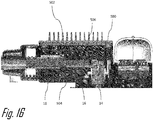
- a fifth cover configuration 500 having passive thermal management mechanism is illustrated in Figs 15 and 16 .
- the cover 500 is formed of a thermally conductive material such an aluminum or copper based material and has a number of parallel cooling fins 502 protruding from the cover 500.
- the cover 500 may be formed of a thermally conductive polymer.
- the cavity 18 is filled with a dielectric thermally conductive potting material 504, such as an epoxy or silicone-based material that is in thermal communication with the cover 500.
- a silicone thermal grease may be applied intermediate the potting material 504 and the interior surface 506 of the cover 500.
- the cavity 18 may be filled with a dielectric phase changing material (PCM).
- PCM is a substance with a high heat of fusion, e.g. paraffins or lipids.
- the PCM melts and solidifies at a near constant temperature and can store and releasing large amounts of thermal energy. Heat is absorbed within the cavity 18 as the PCM gradually changes from a solid state to a liquid state when power is flowing through the terminals 14, 20 and then heat is gradually released through the cover 500 as the PCM changes from the liquid state back to the solid state when power is no longer flowing through the terminals 14, 20.
- the potting material 504 and the phase change material used must have a breakdown voltage that is higher than the charging voltage of the vehicle charging system to which the assembly 10 is connected.
- the thermal potting material 504 or PCM of the fifth cover configuration 500 may be incorporated into the first, second or third cover configurations 100, 200, 300.
- the cooling fins 502 of the fifth cover configuration 500 could be integrated into the first, second, third, or fourth cover configuration 100, 200, 300, 400.
- the cover 600 is in intimate thermal and physical contact with busbars that are a part of the DC terminals 14 within the cavity 18.
- the cover 600 includes a top cover 626 having a liquid inlet port 604 and a liquid outlet port 606 that is interconnected with the vehicle's cooling system 24, e.g. a liquid cooling system that cools the vehicle battery pack 22 and/or the vehicle power electronics similar to the illustration of Fig. 8 .
- the vehicle's cooling system 24 includes a pump that causes the liquid coolant to flow through the cooling duct.
- the liquid inlet port 604 and the liquid outlet port 606 may be interconnected with a cooling system dedicated to cooling the assembly 10.
- the top cover 626 may be advantageously formed of a polymeric material to reduce weight of the top cover 626 and provide better electrical isolation compared to a metal top cover 626.
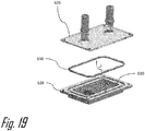
- the cover 600 also includes a bottom cover 628 that defines a coolant duct having a plurality of cooling fins 630 that define a plurality of coolant channels 632, best illustrated in Fig. 20 , through which a liquid coolant flows from the liquid inlet port 604 to the liquid outlet port 606.
- the bottom cover 628 may be advantageously formed of a metallic material to optimize heat transfer between the cooling fins 630 and the liquid coolant. As illustrated in Fig. 20 , it is the bottom cover 628 that is in intimate thermal contact with the busbar portion of the DC terminals 14.
- the bottom cover 628 further includes a dielectric thermal interface material layer 634, such as THERM-A-GAPTM GEL 30 distributed by Parker Chomerics of Woburn Massachusetts, that is in direct contact with the DC terminals 14 and an additional dielectric material layer 636, such as ISOEDGE PR4305 distributed by Henkel Corporation of Warren, Michigan, that is disposed intermediate the dielectric thermal interface material layer 634 and the coolant channels 632.
- the dielectric thermal interface material layer 634 and the additional dielectric material layer 636 provide robust electrical isolation between the busbar portion of the DC terminals 14 and the metallic bottom cover 628.
- the cover 600 also includes a primary coolant seal 638 between the top cover 626 and the bottom cover 628 and a secondary seal 640 between the cover 600 and the cavity 18 to ensure that the liquid coolant does not enter the cavity 18.
- the primary and secondary seals 638, 640 are advantageously formed of a compliant material, such as a silicone-based rubber material. The primary and secondary seals 638, 640 inhibit ingress of the liquid coolant into the cavity 18 that could cause a short circuit between the DC terminals 14.
- Figs. 21-24B show experimental results of the cooling performance of the cover 600 .
- Fig. 21 shows the temperature 642 of one of the electrical terminals 12, the temperature 644 of one of the terminals 14, and the inlet coolant temperature 646 as the assembly 10 is operated with a current of 500 amperes.
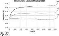
- Fig. 22 shows the temperature 648 of one of the electrical terminals 12, the temperature 650 of one of the terminals 14, and the inlet coolant temperature 652 as the assembly 10 is operated with a current of 500 amperes.
- Fig. 21 shows the temperature 642 of one of the electrical terminals 12, the temperature 644 of one of the terminals 14, and the inlet coolant temperature 646 as the assembly 10 is operated with a current of 500 amperes.
- Fig. 22 shows the temperature 648 of one of the electrical terminals 12, the temperature 650 of one of the terminals 14, and the inlet coolant temperature 652 as the assembly 10 is operated with a current of 500 amperes.
- FIG. 23 shows a comparison of the temperature 654 of one of the electrical terminals 12 and the temperature 656 of one of the terminals 14 with a cover having passive cooling, such as cover 100 with the temperature 658 of one of the electrical terminals 12, the temperature 660 of one of the terminals 14, and the inlet coolant temperature 662 as the assembly 10 under similar operating conditions.
- Fig. 24A shows the thermal gradient between the liquid inlet port 604 and the liquid outlet port 606 of the top cover 626 when the dissipated power is 100 watts.
- Fig. 24B shows the thermal gradient between the terminals 14 and the top cover 626 when the dissipated power is 100 watts.
- cover 600 is configured to conduct a liquid coolant
- other embodiments of the cover 600 may be envisioned that are configured to conduct a gaseous coolant.
- Table 1 describes at least some of the possible combinations. Table 1 - Cover Configurations Type Cavity Contents Cover Configuration Additional Components Passive 1 Still Air Polymer None Passive 2 Thermal Potting Material Thermally Conductive Polymer None Passive 3 Thermal Potting Material Externally Finned Metal None Passive 4 Phase Change Material Thermally Conductive Polymer None Passive 5 Phase Change Material Externally Finned Metal None Passive 6 Still Air Thermally Conductive Polymer Thermal Interface Material Passive 7 Still Air Externally Finned Metal Thermal Interface Material Active 1 Moving Air Polymer with Ports and Baffles None Active 2 Thermal Potting Material Cooling Plate None Active 3 Thermal Potting Material Cooling Plate Thermoelectric Device Active 4 Still Air Pass Trough Cooled Polymer Terminal Position Assurance Device Active 5 Still Air Pass Trough Cooled Metallic Isolated Terminal Position Assurance Device Active 6 Still Air Cooling Plate Thermal Interface Material Active 7 Still Air Cooling Plate with Internal Fins Thermal Interface Material Layer, Insulation Layer, Primary and Secondary Seals
- Figs. 25A-25D illustrate an electrical connector assembly that includes temperature sensing capability for terminals within the assembly.
- An electrical temperature sensor is near the electrical terminals to improve thermal sensing response time for the terminals.
- Thermal contacts are used to bridge the distance between the terminal and the temperature sensors, thereby further improving improve thermal sensing response time for the terminals.
- the electrical connector assembly 10 includes a printed circuit board 712 that has an electrical temperature sensor 714, such as a surface mounted thermistor mounted on the printed circuit board 712.
- the electrical connector assembly 10 also includes at least one terminal 716 that is disposed within an aperture 718 extending through the printed circuit board 712.
- the electrical connector assembly 10 further includes a thermally conductive contact spring 720 that is attached to the printed circuit board 712 in a location proximate to the electrical temperature sensor 714. As best shown in Fig.
- the electrical connector assembly 10 may additionally include a thermally conductive material 722 that covers a portion of the spring 720 where it is attached to the printed circuit board 712 and extends to also cover the electrical temperature sensor 714.
- the contact spring 720 may also be used to transmit electrical signals between the printed circuit board 712 and the terminal 716.
- the printed circuit board 712 may have several electrical temperature sensors 716 mounted thereon as shown in Fig. 25B and the electrical temperature sensors 716 may share a common ground circuit.
- electrical connecter assembly 10 is a vehicle charging port
- other embodiments of this invention may be envisioned for many other types of electrical connector assemblies.
- an electrical connector assembly 10 is provided.
- the assembly 10 provides the benefits of thermally managing the temperature of the assembly 10.
- the assembly 10 also provides a common housing 16 that accepts number of cover configurations 100, 200, 300, 400, 500, 600 with different thermal management mechanisms, allowing the assembly 10 to be customized based on the thermal load and cooling infrastructure, e.g. liquid coolant availability, airflow availability, for the particular application of the assembly 10.
- An electrical connector assembly comprising: a connector housing defining a cavity in which an electrical busbar is disposed, wherein the connector housing defines an opening to the cavity; and a cover attached to the connector housing and configured to cool the busbar, arranged proximate the busbar to extract heat from the busbar.
- Clause 2 The electrical connector assembly of claim 1, wherein the cover includes a coolant channel in fluidic communication with an inlet port and an outlet port and wherein a portion of the cover is in thermal contact with the electrical busbar.
- Clause 3 The electrical connector assembly of clause 2, wherein the portion of the cover in intimate thermal contact with the electrical busbar and forms a cooling plate configured to cool the busbar.
- Clause 6 The electrical connector assembly of clause 2, wherein the cover comprises a plurality of fins extending into the coolant channel which divides the coolant channel into a plurality of coolant channels that are in fluidic communication with the inlet port and the outlet port.
- Clause 7 The electrical connector assembly of clause 2, wherein the assembly includes a pair of electrical busbars and wherein the cover has a dielectric thermal interface material layer which in intimate thermal contact with the pair of electrical busbars, thereby electrically isolating the pair of electrical busbars from one another.
- Clause 8 The electrical connector assembly of clause 7, wherein the cover has an additional dielectric material layer between the dielectric thermal interface material layer and the pair of electrical busbars, thereby electrically isolating the pair of electrical busbars from one another.
- Clause 9 The electrical connector assembly of clause 2, wherein the cover includes a primary seal disposed between a first cover portion defining the inlet port and the outlet port and a second cover portion that is in intimate thermal contact with the electrical busbar.
- Clause 10 The electrical connector assembly of clause 9, wherein the assembly further includes a secondary seal disposed between the cover and the connector housing.
- a cover assembly configured to enclose an opening to a cavity of a connector housing in which an electrical busbar is disposed within the cavity, the cover assembly comprising: an inlet port; an outlet port; and a coolant channel in fluidic communication with the inlet port and the outlet port, wherein the cover assembly is configured to be in thermal communication with the electrical busbar.
- Clause 12 The cover assembly of clause 11, wherein the cover assembly comprises a plurality of fins extending into the coolant channel which define a plurality of coolant channels in fluidic communication with the inlet port and the outlet port.
- Clause 13 The cover assembly of clause 11 or 12, wherein the cover has a dielectric thermal interface material layer which is configured to be in thermal communication with the electrical busbar and an additional dielectric material layer configured to be located between the dielectric thermal interface material layer and the electrical busbar.
- Clause 14 The cover assembly of any one of the clauses 12-14, further comprising: a primary seal disposed between a first cover portion defining the inlet port and the outlet port and a second cover portion in intimate thermal contact with the electrical busbar; and a secondary seal configured to be disposed between the second cover portion and the connector housing.
- An electrical connector assembly comprising: a printed circuit board having an electrical temperature sensor disposed thereon; a terminal disposed within an aperture extending through the printed circuit board; and a thermally conductive spring attached to the printed circuit board in a location proximate the electrical temperature sensor.
- Clause 16 The electrical connector assembly according to clause 15, further comprising: a thermally conductive material covering a portion of the spring attached to the printed circuit board and the electrical temperature sensor and wherein the electrical temperature sensor is a surface mounted thermistor.
- An electrical connector assembly comprising: a connector housing defining a cavity in which an electrical busbar is disposed, wherein the connector housing defines an opening to the cavity; and a cover attached to the connector housing and configured to cool the busbar, wherein the cover is selected from a plurality of cover designs configured to actively or passively cool the busbar.
- 'one or more' includes a function being performed by one element, a function being performed by more than one element, e.g., in a distributed fashion, several functions being performed by one element, several functions being performed by several elements, or any combination of the above.
- first, second, etc. are, in some instances, used herein to describe various elements, these elements should not be limited by these terms. These terms are only used to distinguish one element from another.
- a first contact could be termed a second contact, and, similarly, a second contact could be termed a first contact, without departing from the scope of the various described embodiments.
- the first contact and the second contact are both contacts, but they are not the same contact.
- the term “if' is, optionally, construed to mean “when” or “upon” or “in response to determining” or “in response to detecting,” depending on the context.
- the phrase “if it is determined” or “if [a stated condition or event] is detected” is, optionally, construed to mean “upon determining” or “in response to determining” or “upon detecting [the stated condition or event]” or “in response to detecting [the stated condition or event],” depending on the context.
Landscapes
- Engineering & Computer Science (AREA)
- Power Engineering (AREA)
- Transportation (AREA)
- Mechanical Engineering (AREA)
- Physics & Mathematics (AREA)
- Thermal Sciences (AREA)
- Microelectronics & Electronic Packaging (AREA)
- Chemical & Material Sciences (AREA)
- Dispersion Chemistry (AREA)
- Connector Housings Or Holding Contact Members (AREA)
Abstract
Description
- The invention relates to electrical connector assemblies, particularly electrical connector assemblies with liquid cooling features and/or temperature monitoring.
- The invention relates to electrical connectors, particularly electrical connectors configured to accommodate a variety of different modular cooling features.
- High power electrical connector assemblies, such as those used with fast charging systems for electrical vehicles must be designed to carry 90 kilowatts of electrical power or more. Contact resistance between electrical terminal elements in the electrical connector assembly may cause power losses which are converted to thermal energy within the connector assembly. This thermal energy can cause a temperature rise within the electrical connector assembly that may damage the assembly if thermal limits are exceeded. Managing the terminal energy is also important in meeting industry performance standards, e.g. performance standards published by Underwriters Laboratories (UL), Society of Automotive Engineers (SAE), and/or the International Electrotechnical Commission (IEC).
- The subject matter discussed in the background section should not be assumed to be prior art merely because of its mention in the background section. Similarly, a problem mentioned in the background section or associated with the subject matter of the background section should not be assumed to have been previously recognized in the prior art. The subject matter in the background section merely represents different approaches, which in and of themselves may also be inventions.
- According to one embodiment of the invention, an electrical connector assembly is provided. The electrical connector assembly includes a connector housing defining a cavity in which an electrical busbar is disposed. The connector housing defines an opening to the cavity. The electrical connector assembly also includes a cover attached to the housing and configured to cool the busbar. The cover has at least one of the following features:
- a) an inlet port (102) in fluidic communication with an outlet port (106) via a coolant channel (102),
- b) a thermoelectric device (202),
- c) an inlet port (304) in fluidic communication with an outlet port (306) configured to carry a liquid coolant flow through a terminal position assurance member,
- d) an inlet port (402) in pneumatic communication with an outlet port (404) via the cavity (18),
- e) a plurality of cooling fins (502) extending from the cover (500), and
- f) a plurality of fins (630) extending into the coolant channel (632) which define a plurality of coolant channels (632) in fluidic communication with the inlet port (604) and the outlet port (606).
- In an example embodiment having one or more features of the electrical connector assembly of the previous paragraph, the cover may define a planar section which is in the intimate thermal contact with the electrical busbar.
- In an example embodiment having one or more features of the electrical connector assembly any one of the previous paragraphs, the cover may include a plurality of fins extending into the coolant channels which divide the coolant channel into a plurality of coolant channels that are in fluidic communication with the inlet port and the outlet port.
- In an example embodiment having one or more features of the electrical connector assembly any one of the previous paragraphs, the cover may have a dielectric thermal interface material layer which in the intimate thermal contact with the electrical busbar.
- In an example embodiment having one or more features of the electrical connector assembly any one of the previous paragraphs, the cover may include an additional dielectric material layer between the dielectric thermal interface material layer and the electrical busbar.
- In an example embodiment having one or more features of the electrical connector assembly any one of the previous paragraphs, the cover may include a primary seal disposed between a first cover portion defining the inlet port and the outlet port and a second cover portion that is in intimate thermal contact with the electrical busbar.
- In an example embodiment having one or more features of the electrical connector assembly any one of the previous paragraphs, the assembly may further include a secondary seal that is disposed between the cover and the connector housing.
- In an example embodiment having one or more features of the electrical connector assembly any one of the previous paragraphs, the first cover portion may be formed of a polymeric material and the second cover portion may be formed of a metallic material.
- In an example embodiment having one or more features of the electrical connector assembly any one of the previous paragraphs, the inlet port and the outlet port may be interconnected to a liquid cooling system of an electrically propelled vehicle.
- According to another embodiment of the invention, a cover assembly configured to enclose an opening to a cavity of a connector housing in which an electrical busbar is disposed within the cavity is provided. The cover assembly includes an inlet port, an outlet port, and a coolant channel in fluidic communication with the inlet port and the outlet port. The cover assembly is configured to be in thermal communication with the electrical busbar.
- In an example embodiment having one or more features of the cover assembly of the previous paragraph, the cover assembly may include a plurality of fins extending into the coolant channel. The cooling fins define a plurality of coolant channels in fluidic communication with the inlet port and the outlet port.
- In an example embodiment having one or more features of the cover assembly of one of the previous paragraphs, the cover may have a dielectric thermal interface material layer which is configured to be in thermal communication with the electrical busbar. The cover may also have an additional dielectric material layer configured to be located between the dielectric thermal interface material layer and the electrical busbar.
- In an example embodiment having one or more features of the cover assembly of one of the previous paragraphs, the cover assembly may further include a primary seal disposed between a first cover portion defining the inlet port and the outlet port and a second cover portion in intimate thermal contact with the electrical busbar and a secondary seal configured to be disposed between the second cover portion and the connector housing.
- In an example embodiment having one or more features of the cover assembly of one of the previous paragraphs, the first cover portion may be formed of a polymeric material and the second cover portion may be formed of a metallic material.
- According to yet another embodiment of the invention, an electrical connector assembly is provided. The electrical connector assembly a printed circuit board having an electrical temperature sensor disposed thereon, a terminal disposed within an aperture extending through the printed circuit board, and a thermally conductive spring attached to the printed circuit board in a location proximate the electrical temperature sensor.
- In an example embodiment having one or more features of the electrical connector assembly of the previous paragraph, the assembly may further include a thermally conductive material covering a portion of the spring attached to the printed circuit board and the electrical temperature sensor.
- In an example embodiment having one or more features of the electrical connector assembly any one of the previous paragraphs, the electrical temperature sensor may be a surface mounted thermistor.
- The present invention will now be described, by way of example with reference to the accompanying drawings, in which:
-
Fig. 1 is perspective front view of an electrical connector assembly according to one embodiment of the invention; -
Fig. 2 is an exploded perspective rear view of the electrical connector assembly ofFig. 1 showing a plurality of different cover configurations according to one embodiment of the invention; -
Fig. 3 is a close-up perspective rear view of an opening in a connector housing of the electrical connector assembly ofFig. 1 according to one embodiment of the invention; -
Fig. 4 is a perspective left side view of the electrical connector assembly ofFig. 1 showing a cover having coolant tube running through the cover according to one embodiment of the invention; -
Fig. 5 is a perspective right side view of the electrical connector assembly ofFig. 4 according to one embodiment of the invention; -
Fig. 6 is a perspective rear view of the electrical connector assembly ofFig. 4 according to one embodiment of the invention; -
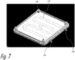
Fig. 7 is a perspective bottom view of the cover ofFig. 6 according to one embodiment of the invention; -
Fig. 8 is a schematic diagram of the coolant tube of the electrical connector assembly ofFig. 4 interconnected with a cooling system of an electrically propelled vehicle according to one embodiment of the invention; -
Fig. 9 is an exploded view of the electrical connector assembly ofFig. 4 including a thermoelectric device according to one embodiment of the invention; -
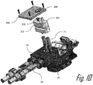
Fig. 10 is an exploded view of the electrical connector assembly ofFig. 1 showing a member having a coolant duct terminated by a pair of liquid ports according to one embodiment of the invention; -
Fig. 11 is a perspective left side view of the electrical connector assembly ofFig. 10 showing a cover having the pair of liquid ports extending through an aperture in the cover according to one embodiment of the invention; -
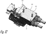
Fig. 12 is a perspective right side view of the electrical connector assembly ofFig. 1 showing a cover having a pair of airflow ports extending through the cover according to one embodiment of the invention; -
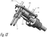
Fig. 13 is a partial exploded view of the electrical connector assembly ofFig. 12 showing the cover and an interconnection between a pair of terminals according to one embodiment of the invention; -
Fig. 14 is a perspective bottom view of the cover of the electrical connector assembly ofFig. 12 showing a baffle according to one embodiment of the invention; -
Fig. 15 is a perspective rear view of the electrical connector assembly ofFig. 1 showing a cover having a plurality of cooling fins extending from the cover according to one embodiment of the invention; -
Fig. 16 is a cross section view of the electrical connector assembly ofFig. 15 according to one embodiment of the invention; -
Fig. 17 is an exploded perspective view of an electrical connector assembly according to one embodiment of the invention; -
Fig. 18 is an isolated view of a liquid cooling plate of the electrical connector assembly ofFig. 17 according to one embodiment of the invention; -
Fig. 19 is an exploded view of the liquid cooling plate ofFig. 18 while conducting 500 amperes according to one embodiment of the invention; -
Fig. 20 is a cross section view of the electrical connector assembly ofFig. 17 according to one embodiment of the invention; -
Fig. 21 is a graph of the temperature of various components electrical connector assembly ofFig. 17 while conducting 500 amperes according to one embodiment of the invention; -
Fig. 22 is a graph of the temperature of various components electrical connector assembly ofFig. 17 while conducting 600 amperes according to one embodiment of the invention; -
Fig. 23 is a graph of the temperature of various components electrical connector assembly ofFig. 17 compared to an alternative cooling system according to one embodiment of the invention; -
Fig. 24A is a temperature gradient top view of the liquid cooling plate ofFig. 18 according to one embodiment of the invention; -
Fig. 24B is a temperature gradient bottom view of the liquid cooling plate ofFig. 18 according to one embodiment of the invention; -
Fig. 25A is a perspective view of an electrical connector assembly in a partially assembled condition according to another embodiment of the invention; -
Fig. 25B is a front view of a printed circuit board subassembly of the electrical connector assembly ofFig. 25A according to one embodiment of the invention. -
Fig. 25C is a close-up view of the printed circuit board subassembly ofFig. 25B according to one embodiment of the invention; and -
Fig. 25D is a cross-section view of the printed circuit board subassembly ofFig. 25B according to one embodiment of the invention. - Reference will now be made in detail to embodiments, examples of which are illustrated in the accompanying drawings. In the following detailed description, numerous specific details are set forth to provide a thorough understanding of the various described embodiments. However, it will be apparent to one of ordinary skill in the art that the various described embodiments may be practiced without these specific details. In other instances, well-known methods, procedures, components, circuits, and networks have not been described in detail so as not to unnecessarily obscure aspects of the embodiments.
-
Figs. 1 through 16 illustrate a non-limiting example of an electrical connecter assembly embodying features of the invention. The illustrated example of the electrical connector assembly, hereinafter referred to as theassembly 10, serves a charging port of an electrically propelled vehicle. As used herein, the term "electrically propelled vehicle" may refer to an electric vehicle which is propelled solely by an electric motor or a hybrid electric vehicle which is propelled by an electric motor in some combination with a combustion engine. Theassembly 10 as illustrated conforms to Society of Automotive Engineers (SAE) Specification J1772 Combined Charging System. Theassembly 10 has a combination ofelectrical terminals 12 for lower power alternating current (AC) charging of the vehicle battery and a pair ofDC terminals 14 for higher power direct current (DC) charging of the vehicle battery, as shown inFig. 1 . Other charging port standards, such as standards published by the CHAdeMO Association, use a similar pair of DC terminals. - As shown in
Fig. 2 , the assembly includes a connector housing, hereinafter referred to as thehousing 16, that defines acavity 18 in which theDC terminals 14 are disposed. As can be seen by referencingFigs. 3 ,8 , and16 , theDC terminals 14 are interconnected tocable terminals 20 of insulated wire cables connecting theassembly 10 to thebattery pack 22 of the vehicle. TheDC terminals 14 carry power levels of 90 kilowatts or more which can cause the temperature to rise within thecavity 18 during the battery charging operation. Theassembly 10 further includes a cover that is configured to enclose thecavity 18, thereby protecting theDC terminals 14 and thecable terminals 20. The cover is also configured to thermally manage heat within thecavity 18 by removing thermal energy from thecavity 18. - The
housing 16 is designed to receive and accommodate severaldifferent cover configurations cover configurations cavity 18. Thecover configurations cavity 18, one or more thermoelectric cooling plates, and/or one or more airflow ports that are configured to receive an airflow within thecavity 18 and/or passive thermal management mechanisms, such as one ormore cooling fins 502 projecting from thecover 500. - In a
first cover configuration 100 having an active thermal management mechanism shown inFigs. 4-8 , thecover 100 comprises an active thermal management system featuring anenclosed coolant tube 102 that is configured to carry a liquid coolant flow through thecover 100. The coolant tube has aliquid inlet port 104 and aliquid outlet port 106 that is interconnected with the vehicle'scooling system 24, e.g. a liquid cooling system that cools thevehicle battery pack 22 and/or the vehicle power electronics as illustrated inFig. 8 . The vehicle'scooling system 24 includes a pump or other fluid movement device that causes the liquid coolant to flow through the cooling tube. As shown inFigs 4 ,6 , and7 , the coolant tube follows a serpentine path through the cover, thereby increasing the length of the coolant tube and increasing the amount of thermal energy that can be absorbed from thecavity 18 by the coolant it flows through the cover. The cover may preferably be formed on a material with a high thermal conductivity, such as an aluminum or copper-based material, to provide adequate thermal transfer between thecavity 18 and the liquid coolant. Alternatively, the cover may be formed of a thermally conductive polymer. - According to a
second cover configuration 200 an active thermal management mechanism shown inFig. 9 , thecover 200 includes athermoelectric device 202 which uses the Peltier effect to actively cool thecavity 18. An electrical voltage is applied to thethermoelectric device 202 such that a side 204 of thethermoelectric device 202 facing inwardly toward thecavity 18 is cooled while another side 206 of thethermoelectric device 202 facing outward is heated by the thermal energy removed from the cooled side 204. Thethermoelectric device 202 may be used as the sole thermal management mechanism in theassembly 10 or combined with any one of the other describedcover configurations - In a
third cover configuration 300 an active thermal management mechanism illustrated inFigs. 10 and11 , theassembly 10 further comprises an electrically nonconductive terminal position assurance (TPA)member 302 that encloses a portion of theDC terminals 14 and is in thermal communication with theDC terminals 14. TheTPA member 302 comprises a coolant duct configured to carry a liquid coolant flow through theTPA member 302. TheTPA member 302 provide s the benefit of removing thermal energy directly from theDC terminals 14 which are one of the primary heat sources within thecavity 18. The coolant duct has aliquid inlet port 304 and aliquid outlet port 306 that is interconnected with the vehicle'scooling system 24, e.g. a liquid cooling system that cools thevehicle battery pack 22 and/or the vehicle power electronics similar to the illustration ofFig. 8 . The vehicle'scooling system 24 includes a pump that causes the liquid coolant to flow through the cooling duct. Thecover 300 defines anaperture 308 through which theliquid inlet port 304 and theliquid outlet port 306 exit thecavity 18. In an alternative embodiment., theliquid inlet port 304 and theliquid outlet port 306 may be interconnected with a cooling system dedicated to cooling theassembly 10. - A
fourth cover configuration 400 having an active thermal management mechanism is illustrated inFigs. 12-14 . Thecover 400 is in pneumatic and thermal communication with thecavity 18. Thecover 400 includes anairflow inlet port 402 though which airflow of air at the vehicle's ambient temperature enters thecavity 18 and anairflow outlet port 404 through which the airflow is exhausted from thecavity 18. Theairflow inlet port 402 is interconnected to an airflow generating device of the vehicle, such as a ducted fan. The airflow through thecavity 18 removes some of the thermal energy from thecavity 18, thereby lowing the temperature within thecavity 18. An inner surface of thecover 400 defines abaffle 406 configured to direct the airflow within thecavity 18. Thebaffle 406 also includes acurved surface 408 that helps to create a turbulent airflow within thecavity 18. Thecover 400 and thebaffle 406 may be preferably formed of a dielectric polymer material to avoid short circuiting that may be caused by contact between thebaffle 406 and any of the terminals within thecavity 18. - A
fifth cover configuration 500 having passive thermal management mechanism is illustrated inFigs 15 and16 . Thecover 500 is formed of a thermally conductive material such an aluminum or copper based material and has a number ofparallel cooling fins 502 protruding from thecover 500. Alternatively, thecover 500 may be formed of a thermally conductive polymer. In this configuration thecavity 18 is filled with a dielectric thermallyconductive potting material 504, such as an epoxy or silicone-based material that is in thermal communication with thecover 500. A silicone thermal grease may be applied intermediate thepotting material 504 and theinterior surface 506 of thecover 500. - In an alternative embodiment, the
cavity 18 may be filled with a dielectric phase changing material (PCM). A PCM is a substance with a high heat of fusion, e.g. paraffins or lipids. The PCM melts and solidifies at a near constant temperature and can store and releasing large amounts of thermal energy. Heat is absorbed within thecavity 18 as the PCM gradually changes from a solid state to a liquid state when power is flowing through theterminals cover 500 as the PCM changes from the liquid state back to the solid state when power is no longer flowing through theterminals - The
potting material 504 and the phase change material used must have a breakdown voltage that is higher than the charging voltage of the vehicle charging system to which theassembly 10 is connected. - Alternative embodiments of the
assembly 10 may be envisioned combining various elements described above. For example, thethermal potting material 504 or PCM of thefifth cover configuration 500 may be incorporated into the first, second orthird cover configurations fins 502 of thefifth cover configuration 500 could be integrated into the first, second, third, orfourth cover configuration - In a
sixth cover configuration 600, an active thermal management mechanism illustrated inFigs. 17 through 24B , thecover 600 is in intimate thermal and physical contact with busbars that are a part of theDC terminals 14 within thecavity 18. As shown inFig. 18 , thecover 600 includes atop cover 626 having aliquid inlet port 604 and aliquid outlet port 606 that is interconnected with the vehicle'scooling system 24, e.g. a liquid cooling system that cools thevehicle battery pack 22 and/or the vehicle power electronics similar to the illustration ofFig. 8 . The vehicle'scooling system 24 includes a pump that causes the liquid coolant to flow through the cooling duct. In an alternative embodiment, theliquid inlet port 604 and theliquid outlet port 606 may be interconnected with a cooling system dedicated to cooling theassembly 10. Thetop cover 626 may be advantageously formed of a polymeric material to reduce weight of thetop cover 626 and provide better electrical isolation compared to ametal top cover 626. - As shown in
Fig. 19 , thecover 600 also includes abottom cover 628 that defines a coolant duct having a plurality of coolingfins 630 that define a plurality ofcoolant channels 632, best illustrated inFig. 20 , through which a liquid coolant flows from theliquid inlet port 604 to theliquid outlet port 606. Thebottom cover 628 may be advantageously formed of a metallic material to optimize heat transfer between the coolingfins 630 and the liquid coolant. As illustrated inFig. 20 , it is thebottom cover 628 that is in intimate thermal contact with the busbar portion of theDC terminals 14. Thebottom cover 628 further includes a dielectric thermalinterface material layer 634, such as THERM-A-GAP™ GEL 30 distributed by Parker Chomerics of Woburn Massachusetts, that is in direct contact with theDC terminals 14 and an additionaldielectric material layer 636, such as ISOEDGE PR4305 distributed by Henkel Corporation of Warren, Michigan, that is disposed intermediate the dielectric thermalinterface material layer 634 and thecoolant channels 632. The dielectric thermalinterface material layer 634 and the additionaldielectric material layer 636 provide robust electrical isolation between the busbar portion of theDC terminals 14 and themetallic bottom cover 628. - The
cover 600 also includes aprimary coolant seal 638 between thetop cover 626 and thebottom cover 628 and asecondary seal 640 between thecover 600 and thecavity 18 to ensure that the liquid coolant does not enter thecavity 18. The primary andsecondary seals secondary seals cavity 18 that could cause a short circuit between theDC terminals 14. - Experimental results of the cooling performance of the
cover 600 are shown inFigs. 21-24B .Fig. 21 shows thetemperature 642 of one of theelectrical terminals 12, thetemperature 644 of one of theterminals 14, and theinlet coolant temperature 646 as theassembly 10 is operated with a current of 500 amperes.Fig. 22 shows thetemperature 648 of one of theelectrical terminals 12, thetemperature 650 of one of theterminals 14, and theinlet coolant temperature 652 as theassembly 10 is operated with a current of 500 amperes.Fig. 23 shows a comparison of thetemperature 654 of one of theelectrical terminals 12 and thetemperature 656 of one of theterminals 14 with a cover having passive cooling, such ascover 100 with thetemperature 658 of one of theelectrical terminals 12, thetemperature 660 of one of theterminals 14, and theinlet coolant temperature 662 as theassembly 10 under similar operating conditions.Fig. 24A shows the thermal gradient between theliquid inlet port 604 and theliquid outlet port 606 of thetop cover 626 when the dissipated power is 100 watts.Fig. 24B shows the thermal gradient between theterminals 14 and thetop cover 626 when the dissipated power is 100 watts. - While the illustrated embodiment of
cover 600 is configured to conduct a liquid coolant, other embodiments of thecover 600 may be envisioned that are configured to conduct a gaseous coolant. - Alternative embodiments may be envisioned which include features of several of the embodiments described above. Table 1 below describes at least some of the possible combinations.
Table 1 - Cover Configurations Type Cavity Contents Cover Configuration Additional Components Passive 1 Still Air Polymer None Passive 2 Thermal Potting Material Thermally Conductive Polymer None Passive 3 Thermal Potting Material Externally Finned Metal None Passive 4 Phase Change Material Thermally Conductive Polymer None Passive 5 Phase Change Material Externally Finned Metal None Passive 6 Still Air Thermally Conductive Polymer Thermal Interface Material Passive 7 Still Air Externally Finned Metal Thermal Interface Material Active 1 Moving Air Polymer with Ports and Baffles None Active 2 Thermal Potting Material Cooling Plate None Active 3 Thermal Potting Material Cooling Plate Thermoelectric Device Active 4 Still Air Pass Trough Cooled Polymer Terminal Position Assurance Device Active 5 Still Air Pass Trough Cooled Metallic Isolated Terminal Position Assurance Device Active 6 Still Air Cooling Plate Thermal Interface Material Active 7 Still Air Cooling Plate with Internal Fins Thermal Interface Material Layer, Insulation Layer, Primary and Secondary Seals -
Figs. 25A-25D illustrate an electrical connector assembly that includes temperature sensing capability for terminals within the assembly. An electrical temperature sensor is near the electrical terminals to improve thermal sensing response time for the terminals. Thermal contacts are used to bridge the distance between the terminal and the temperature sensors, thereby further improving improve thermal sensing response time for the terminals. - As illustrated in the non-limiting examples of
Figs. 25B-25D , theelectrical connector assembly 10 includes a printedcircuit board 712 that has anelectrical temperature sensor 714, such as a surface mounted thermistor mounted on the printedcircuit board 712. Theelectrical connector assembly 10 also includes at least one terminal 716 that is disposed within anaperture 718 extending through the printedcircuit board 712. Theelectrical connector assembly 10 further includes a thermallyconductive contact spring 720 that is attached to the printedcircuit board 712 in a location proximate to theelectrical temperature sensor 714. As best shown inFig. 25C , theelectrical connector assembly 10 may additionally include a thermallyconductive material 722 that covers a portion of thespring 720 where it is attached to the printedcircuit board 712 and extends to also cover theelectrical temperature sensor 714. Thecontact spring 720 may also be used to transmit electrical signals between the printedcircuit board 712 and the terminal 716. - The printed
circuit board 712 may have severalelectrical temperature sensors 716 mounted thereon as shown inFig. 25B and theelectrical temperature sensors 716 may share a common ground circuit. - While the illustrated example of the
electrical connecter assembly 10 is a vehicle charging port, other embodiments of this invention may be envisioned for many other types of electrical connector assemblies. - Accordingly, an
electrical connector assembly 10 is provided. Theassembly 10 provides the benefits of thermally managing the temperature of theassembly 10. Theassembly 10 also provides acommon housing 16 that accepts number ofcover configurations assembly 10 to be customized based on the thermal load and cooling infrastructure, e.g. liquid coolant availability, airflow availability, for the particular application of theassembly 10. - Although the present disclosure is not so limited, the following numbered clauses demonstrate one or more aspects of the disclosure.
- Clause 1. An electrical connector assembly, comprising: a connector housing defining a cavity in which an electrical busbar is disposed, wherein the connector housing defines an opening to the cavity; and a cover attached to the connector housing and configured to cool the busbar, arranged proximate the busbar to extract heat from the busbar.
- Clause 2. The electrical connector assembly of claim 1, wherein the cover includes a coolant channel in fluidic communication with an inlet port and an outlet port and wherein a portion of the cover is in thermal contact with the electrical busbar.
- Clause 3. The electrical connector assembly of clause 2, wherein the portion of the cover in intimate thermal contact with the electrical busbar and forms a cooling plate configured to cool the busbar.
- Clause 4. The electrical connector assembly of clause 2, wherein a wire cable is attached to the busbar opposite the portion of the cover in thermal contact with the electrical busbar
- Clause 5. The electrical connector assembly of clause 2, wherein the portion of the cover is in thermal contact with the electrical busbar along an entirely of a lower surface of the cover.
- Clause 6. The electrical connector assembly of clause 2, wherein the cover comprises a plurality of fins extending into the coolant channel which divides the coolant channel into a plurality of coolant channels that are in fluidic communication with the inlet port and the outlet port.
- Clause 7. The electrical connector assembly of clause 2, wherein the assembly includes a pair of electrical busbars and wherein the cover has a dielectric thermal interface material layer which in intimate thermal contact with the pair of electrical busbars, thereby electrically isolating the pair of electrical busbars from one another.
- Clause 8. The electrical connector assembly of clause 7, wherein the cover has an additional dielectric material layer between the dielectric thermal interface material layer and the pair of electrical busbars, thereby electrically isolating the pair of electrical busbars from one another.
- Clause 9. The electrical connector assembly of clause 2, wherein the cover includes a primary seal disposed between a first cover portion defining the inlet port and the outlet port and a second cover portion that is in intimate thermal contact with the electrical busbar.
-
Clause 10. The electrical connector assembly of clause 9, wherein the assembly further includes a secondary seal disposed between the cover and the connector housing. - Clause 11. A cover assembly configured to enclose an opening to a cavity of a connector housing in which an electrical busbar is disposed within the cavity, the cover assembly comprising: an inlet port; an outlet port; and a coolant channel in fluidic communication with the inlet port and the outlet port, wherein the cover assembly is configured to be in thermal communication with the electrical busbar.
-
Clause 12. The cover assembly of clause 11, wherein the cover assembly comprises a plurality of fins extending into the coolant channel which define a plurality of coolant channels in fluidic communication with the inlet port and the outlet port. - Clause 13. The cover assembly of
clause 11 or 12, wherein the cover has a dielectric thermal interface material layer which is configured to be in thermal communication with the electrical busbar and an additional dielectric material layer configured to be located between the dielectric thermal interface material layer and the electrical busbar. -
Clause 14. The cover assembly of any one of the clauses 12-14, further comprising: a primary seal disposed between a first cover portion defining the inlet port and the outlet port and a second cover portion in intimate thermal contact with the electrical busbar; and a secondary seal configured to be disposed between the second cover portion and the connector housing. - Clause 15. An electrical connector assembly, comprising: a printed circuit board having an electrical temperature sensor disposed thereon; a terminal disposed within an aperture extending through the printed circuit board; and a thermally conductive spring attached to the printed circuit board in a location proximate the electrical temperature sensor.
-
Clause 16. The electrical connector assembly according to clause 15, further comprising: a thermally conductive material covering a portion of the spring attached to the printed circuit board and the electrical temperature sensor and wherein the electrical temperature sensor is a surface mounted thermistor. - Clause 17. An electrical connector assembly, comprising: a connector housing defining a cavity in which an electrical busbar is disposed, wherein the connector housing defines an opening to the cavity; and a cover attached to the connector housing and configured to cool the busbar, wherein the cover is selected from a plurality of cover designs configured to actively or passively cool the busbar.
- While this invention has been described in terms of the preferred embodiments thereof, it is not intended to be so limited, but rather only to the extent set forth in the claims that follow. For example, the above-described embodiments (and/or aspects thereof) may be used in combination with each other. In addition, many modifications may be made to configure a situation or material to the teachings of the invention without departing from its scope. Dimensions, types of materials, orientations of the various components, and the number and positions of the various components described herein are intended to define parameters of certain embodiments and are by no means limiting and are merely prototypical embodiments.
- As used herein, 'one or more' includes a function being performed by one element, a function being performed by more than one element, e.g., in a distributed fashion, several functions being performed by one element, several functions being performed by several elements, or any combination of the above.
- It will also be understood that, although the terms first, second, etc. are, in some instances, used herein to describe various elements, these elements should not be limited by these terms. These terms are only used to distinguish one element from another. For example, a first contact could be termed a second contact, and, similarly, a second contact could be termed a first contact, without departing from the scope of the various described embodiments. The first contact and the second contact are both contacts, but they are not the same contact.
- The terminology used in the description of the various described embodiments herein is for the purpose of describing embodiments only and is not intended to be limiting. As used in the description of the various described embodiments and the appended claims, the singular forms "a", "an" and "the" are intended to include the plural forms as well, unless the context clearly indicates otherwise. It will also be understood that the term "and/or" as used herein refers to and encompasses all possible combinations of one or more of the associated listed items. It will be further understood that the terms "includes," "including," "comprises," and/or "comprising," when used in this specification, specify the presence of stated features, integers, steps, operations, elements, and/or components, but do not preclude the presence or addition of one or more other features, integers, steps, operations, elements, components, and/or groups thereof.
- As used herein, the term "if' is, optionally, construed to mean "when" or "upon" or "in response to determining" or "in response to detecting," depending on the context. Similarly, the phrase "if it is determined" or "if [a stated condition or event] is detected" is, optionally, construed to mean "upon determining" or "in response to determining" or "upon detecting [the stated condition or event]" or "in response to detecting [the stated condition or event]," depending on the context.
- Additionally, while terms of ordinance or orientation may be used herein these elements should not be limited by these terms. All terms of ordinance or orientation, unless stated otherwise, are used for purposes distinguishing one element from another, and do not denote any order of operations, direction or orientation unless stated otherwise.
Claims (14)
- An electrical connector assembly (10), comprising:a connector housing (16) defining a cavity (18) in which an electrical busbar (14) is disposed, wherein the connector housing (16) defines an opening to the cavity (18); anda cover (600) attached to the connector housing (16) and configured to cool the busbar (14), arranged proximate the busbar (14) to extract heat from the busbar (14).
- The electrical connector assembly (10) of claim 1, wherein the cover includes a coolant channel (632) in fluidic communication with an inlet port (604) and an outlet port (606) and wherein a portion of the cover (600) is in thermal contact with the electrical busbar (14).
- The electrical connector assembly (10) of claim 2, wherein the portion of the cover (600) in intimate thermal contact with the electrical busbar (14) and forms a cooling plate configured to cool the busbar (14).
- The electrical connector assembly (10) of claim 2, wherein a wire cable is attached to the busbar (14) opposite the portion of the cover (600) in thermal contact with the electrical busbar (14)
- The electrical connector assembly (10) of claim 2, wherein the portion of the cover (600) is in thermal contact with the electrical busbar (14) along an entirely of a lower surface of the cover (600).
- The electrical connector assembly (10) of claim 2, wherein the cover (600) comprises a plurality of fins (630) extending into the coolant channel (632) which divides the coolant channel (632) into a plurality of coolant channels (632) that are in fluidic communication with the inlet port (604) and the outlet port (606).
- The electrical connector assembly (10) of claim 2, wherein the assembly includes a pair of electrical busbars and wherein the cover (600) has a dielectric thermal interface material layer (634) which in intimate thermal contact with the pair of electrical busbars (14), thereby electrically isolating the pair of electrical busbars (14) from one another.
- The electrical connector assembly (10) of claim 7, wherein the cover (600) has an additional dielectric material layer (636) between the dielectric thermal interface material layer (643) and the pair of electrical busbars (14), thereby electrically isolating the pair of electrical busbars (14) from one another.
- The electrical connector assembly (10) of claim 2, wherein the cover (600) includes a primary seal (638) disposed between a first cover portion defining the inlet port (604) and the outlet port (606) and a second cover portion that is in intimate thermal contact with the electrical busbar (14).
- The electrical connector assembly (10) of claim 9, wherein the assembly (10) further includes a secondary seal (640) disposed between the cover (600) and the connector housing (16).
- A cover assembly (100, 600) configured to enclose an opening to a cavity (18) of a connector housing (16) in which an electrical busbar (14) is disposed within the cavity (18), the cover assembly (100, 600) comprising:an inlet port (104, 604);an outlet port (106, 606); anda coolant channel (102, 632) in fluidic communication with the inlet port (104, 604) and the outlet port (106, 606), wherein the cover assembly (100, 600) is configured to be in thermal communication with the electrical busbar (14).
- The cover assembly (600) of claim 11, wherein the cover assembly (600) comprises a plurality of fins (630) extending into the coolant channel (632) which define a plurality of coolant channels (632) in fluidic communication with the inlet port (604) and the outlet port (606).
- The cover assembly (600) of claim 11 or 12, wherein the cover has a dielectric thermal interface material layer (634) which is configured to be in thermal communication with the electrical busbar (14) and an additional dielectric material layer (636) configured to be located between the dielectric thermal interface material layer (634) and the electrical busbar (14).
- The cover assembly (600) of any one of the claims 12-14, further comprising:a primary seal (638) disposed between a first cover portion defining the inlet port (604) and the outlet port (606) and a second cover portion in intimate thermal contact with the electrical busbar (14); anda secondary seal (640) configured to be disposed between the second cover portion and the connector housing (16).
Applications Claiming Priority (2)
| Application Number | Priority Date | Filing Date | Title |
|---|---|---|---|
| US201962897571P | 2019-09-09 | 2019-09-09 | |
| US16/801,245 US11511636B2 (en) | 2019-04-01 | 2020-02-26 | Electrical connector assembly with liquid cooling features |
Publications (2)
| Publication Number | Publication Date |
|---|---|
| EP3793038A1 true EP3793038A1 (en) | 2021-03-17 |
| EP3793038B1 EP3793038B1 (en) | 2024-07-24 |
Family
ID=72292463
Family Applications (2)
| Application Number | Title | Priority Date | Filing Date |
|---|---|---|---|
| EP20195130.8A Active EP3790120B1 (en) | 2019-09-09 | 2020-09-08 | Electrical terminal seal and electrical connector containing same |
| EP20195128.2A Active EP3793038B1 (en) | 2019-09-09 | 2020-09-08 | Electrical connector assembly |
Family Applications Before (1)
| Application Number | Title | Priority Date | Filing Date |
|---|---|---|---|
| EP20195130.8A Active EP3790120B1 (en) | 2019-09-09 | 2020-09-08 | Electrical terminal seal and electrical connector containing same |
Country Status (3)
| Country | Link |
|---|---|
| US (1) | US11539158B2 (en) |
| EP (2) | EP3790120B1 (en) |
| CN (2) | CN118920209A (en) |
Cited By (7)
| Publication number | Priority date | Publication date | Assignee | Title |
|---|---|---|---|---|
| US20220393372A1 (en) * | 2021-06-04 | 2022-12-08 | Aptiv Technologies Limited | Cooled inlet cold plate design for robust electrical isolation |
| EP4272994A1 (en) * | 2022-05-02 | 2023-11-08 | Aptiv Technologies Limited | Electrical connector for vehicle charging inlet |
| EP4324686A1 (en) * | 2022-08-19 | 2024-02-21 | Lisa Dräxlmaier GmbH | Contact element for a plug-in connection device and plug-in connection device |
| EP4362238A1 (en) * | 2022-10-24 | 2024-05-01 | Phoenix Contact e-Mobility GmbH | Contact assembly for an electrical connector having a heat capacity element arranged on a contact element |
| WO2024088742A1 (en) * | 2022-10-24 | 2024-05-02 | Phoenix Contact E-Mobility Gmbh | Load contact assembly comprising a heat capacity element |
| EP4593539A4 (en) * | 2022-09-21 | 2025-12-24 | Changchun Jetty Automotive Tech Co Ltd | CONNECTOR WITH COOLING MODULE |
| EP4683044A3 (en) * | 2024-07-16 | 2026-02-25 | Eaton Intelligent Power Limited | Busbars for a power distribution unit |
Families Citing this family (6)
| Publication number | Priority date | Publication date | Assignee | Title |
|---|---|---|---|---|
| US12500398B2 (en) | 2018-10-31 | 2025-12-16 | Lear Corporation | Electrical assembly |
| DE102021105716B4 (en) | 2021-03-10 | 2023-11-16 | Te Connectivity Germany Gmbh | Electrical connector |
| DE102022100220A1 (en) * | 2021-04-06 | 2022-10-06 | Lear Corporation | electrical arrangement |
| EP4089849A1 (en) * | 2021-05-12 | 2022-11-16 | Aptiv Technologies Limited | High power electrical header connector with cooling features |
| US20230085351A1 (en) * | 2021-09-10 | 2023-03-16 | Aptiv Technologies Limited | Serviceable power inlet connector |
| CN113733962B (en) * | 2021-11-03 | 2021-12-28 | 深圳智电新能源科技有限公司 | Anti-creeping charging pile based on new energy automobile and anti-creeping method thereof |
Citations (4)
| Publication number | Priority date | Publication date | Assignee | Title |
|---|---|---|---|---|
| DE202008006117U1 (en) * | 2008-05-03 | 2008-07-24 | Lumberg Connect Gmbh | Connection box for connecting a solar module |
| EP2242100A1 (en) * | 2008-02-06 | 2010-10-20 | Honda Motor Co., Ltd. | Cooling device and electric vehicle using the cooling device |
| DE102009041968A1 (en) * | 2009-09-21 | 2011-04-07 | Telegärtner Gerätebau GmbH | Junction box arrangement for the electrical connection of a solar module |
| US9192075B1 (en) * | 2014-07-29 | 2015-11-17 | Tyco Electronics Brasil Ltda | Wire dress cover |
Family Cites Families (42)
| Publication number | Priority date | Publication date | Assignee | Title |
|---|---|---|---|---|
| JPH08180928A (en) * | 1994-10-24 | 1996-07-12 | Yazaki Corp | Waterproof connector |
| US5720629A (en) * | 1996-10-16 | 1998-02-24 | The Whitaker Corporation | Sealed electrical connector |
| US6203208B1 (en) * | 1998-11-05 | 2001-03-20 | Illinois Tool Works Inc. | Fiber optic lighting system connector coupling medium |
| JP3380528B2 (en) * | 2000-07-13 | 2003-02-24 | 日本圧着端子製造株式会社 | Waterproof connector |
| US6913486B2 (en) * | 2002-11-07 | 2005-07-05 | Sumitomo Wiring Systems, Ltd. | Waterproof electrical connector |
| JP4214898B2 (en) * | 2003-11-27 | 2009-01-28 | 住友電装株式会社 | Waterproof connector |
| US7744390B2 (en) | 2005-07-28 | 2010-06-29 | Fci Americas Technology, Inc. | Electrical connector assembly with connection assist |
| DE102005056328B4 (en) | 2005-11-25 | 2008-01-31 | Woco Industrietechnik Gmbh | Seal, in particular sealing mat, for at least one electrical connector |
| US7371115B1 (en) | 2006-12-15 | 2008-05-13 | Delphi Technologies, Inc. | Mat seal device |
| DE502007003871D1 (en) | 2007-09-28 | 2010-07-01 | Eberspaecher Controls Gmbh & C | Busbar with heat dissipation |
| JP4951465B2 (en) * | 2007-10-29 | 2012-06-13 | 第一電子工業株式会社 | Electrical connector |
| KR101348041B1 (en) | 2007-12-13 | 2014-01-03 | 델파이 커넥션 시스템즈 홀딩 프랑스 | Electrical connector comprising a sealing mat |
| JP2010245174A (en) | 2009-04-02 | 2010-10-28 | Denso Corp | Electronic control unit and manufacturing method thereof |
| JP5521777B2 (en) * | 2010-05-26 | 2014-06-18 | 住友電装株式会社 | Seal structure of wire lead-out hole |
| DE202010017443U1 (en) | 2010-07-23 | 2012-04-17 | Brose Fahrzeugteile GmbH & Co. Kommanditgesellschaft, Würzburg | Electrical assembly |
| JP5922664B2 (en) * | 2010-10-29 | 2016-05-24 | デルフィ・コネクション・システムズ・ホールディング・フランス | Connector device and connector assembly for vehicle power supply |
| DE102011001471A1 (en) | 2011-03-22 | 2012-09-27 | Amphenol-Tuchel Electronics Gmbh | Electrical connector and insulator |
| CN103988302A (en) | 2012-01-25 | 2014-08-13 | 富士电机株式会社 | Power conversion device |
| US20140308551A1 (en) | 2013-04-15 | 2014-10-16 | GM Global Technology Operations LLC | Series cooled module cooling fin |
| US9277683B2 (en) | 2013-09-19 | 2016-03-01 | Siemens Aktiengesellschaft | Liquid cooled electronic modules and methods for replacing the same |
| JP5995147B2 (en) | 2013-09-24 | 2016-09-21 | 住友電装株式会社 | Circuit structure |
| US10090657B2 (en) | 2014-05-09 | 2018-10-02 | AutoNetworks Technolgies, Ltd. | Circuit assembly, connected busbar structure, and electrical junction box |
| US9655281B2 (en) | 2015-06-26 | 2017-05-16 | Seagate Technology Llc | Modular cooling system |
| JP6468130B2 (en) | 2015-08-28 | 2019-02-13 | 株式会社オートネットワーク技術研究所 | Circuit assembly and electrical junction box |
| GB2545446B (en) | 2015-12-16 | 2018-08-22 | Ge Aviat Systems Ltd | Power distribution connector |
| EP3190670B1 (en) | 2016-01-07 | 2021-03-24 | Aptiv Technologies Limited | Conduit seal and vibration damper |
| EP3411883B1 (en) | 2016-02-01 | 2023-08-23 | Huber+Suhner AG | Cable assembly |
| DE102016107401A1 (en) | 2016-02-26 | 2017-08-31 | Amad Mennekes Holding Gmbh & Co. Kg | Plug-in device with temperature detection |
| US10717367B1 (en) | 2016-03-11 | 2020-07-21 | Apple Inc. | Thermal control systems for battery charging |
| DE102016105311A1 (en) | 2016-03-22 | 2017-09-28 | Phoenix Contact E-Mobility Gmbh | Connector part with a cooled contact element |
| DE102016112279A1 (en) | 2016-07-05 | 2018-01-11 | Te Connectivity Germany Gmbh | Contact device for high current transmission |
| US10148032B1 (en) * | 2017-06-05 | 2018-12-04 | Delphi Technologies, Inc. | Sealed electrical connector assembly and wire seal |
| US10490932B1 (en) | 2018-07-20 | 2019-11-26 | Delphi Technologies, Llc | Connector-assembly with cavity-plug-retainer |
| CH715611B1 (en) | 2018-12-05 | 2022-05-13 | BRUGG eConnect AG | Connection element for the electrical connection of a fluid-coolable individual line, fluid-coolable individual line unit and charging cable. |
| US10622755B1 (en) | 2019-03-07 | 2020-04-14 | Aptiv Technologies Limited | Connector assembly and method of assembling same |
| US10756498B1 (en) | 2019-03-22 | 2020-08-25 | Te Connectivity Corporation | Terminal heat exchanger for an electrical connector |
| US11495908B2 (en) | 2019-04-01 | 2022-11-08 | Aptiv Technologies Limited | Electrical connector assembly with liquid cooling features |
| US11664545B2 (en) | 2019-04-26 | 2023-05-30 | Hanon Systems | Fast charging cooling loop heat exchanger |
| US11285832B2 (en) | 2019-06-05 | 2022-03-29 | TE Connectivity Services Gmbh | Heat exchanger for a power connector |
| US11180044B2 (en) | 2019-06-14 | 2021-11-23 | Honda Motor Co., Ltd. | Electric vehicle cooling system |
| US11846475B2 (en) | 2019-08-26 | 2023-12-19 | Te Connectivity Solutions Gmbh | Heat exchanger for a power connector |
| US11951857B2 (en) | 2020-11-04 | 2024-04-09 | Ford Global Technologies, Llc | Liquid cooled electrical connectors |
-
2020
- 2020-08-21 US US16/999,404 patent/US11539158B2/en active Active
- 2020-09-08 EP EP20195130.8A patent/EP3790120B1/en active Active
- 2020-09-08 EP EP20195128.2A patent/EP3793038B1/en active Active
- 2020-09-09 CN CN202411166119.6A patent/CN118920209A/en active Pending
- 2020-09-09 CN CN202010940217.6A patent/CN112467487A/en active Pending
Patent Citations (4)
| Publication number | Priority date | Publication date | Assignee | Title |
|---|---|---|---|---|
| EP2242100A1 (en) * | 2008-02-06 | 2010-10-20 | Honda Motor Co., Ltd. | Cooling device and electric vehicle using the cooling device |
| DE202008006117U1 (en) * | 2008-05-03 | 2008-07-24 | Lumberg Connect Gmbh | Connection box for connecting a solar module |
| DE102009041968A1 (en) * | 2009-09-21 | 2011-04-07 | Telegärtner Gerätebau GmbH | Junction box arrangement for the electrical connection of a solar module |
| US9192075B1 (en) * | 2014-07-29 | 2015-11-17 | Tyco Electronics Brasil Ltda | Wire dress cover |
Cited By (10)
| Publication number | Priority date | Publication date | Assignee | Title |
|---|---|---|---|---|
| US20220393372A1 (en) * | 2021-06-04 | 2022-12-08 | Aptiv Technologies Limited | Cooled inlet cold plate design for robust electrical isolation |
| US12355201B2 (en) * | 2021-06-04 | 2025-07-08 | Aptiv Technologies AG | Cooled inlet cold plate design for robust electrical isolation |
| EP4272994A1 (en) * | 2022-05-02 | 2023-11-08 | Aptiv Technologies Limited | Electrical connector for vehicle charging inlet |
| EP4324686A1 (en) * | 2022-08-19 | 2024-02-21 | Lisa Dräxlmaier GmbH | Contact element for a plug-in connection device and plug-in connection device |
| EP4593539A4 (en) * | 2022-09-21 | 2025-12-24 | Changchun Jetty Automotive Tech Co Ltd | CONNECTOR WITH COOLING MODULE |
| EP4362238A1 (en) * | 2022-10-24 | 2024-05-01 | Phoenix Contact e-Mobility GmbH | Contact assembly for an electrical connector having a heat capacity element arranged on a contact element |
| WO2024088742A1 (en) * | 2022-10-24 | 2024-05-02 | Phoenix Contact E-Mobility Gmbh | Load contact assembly comprising a heat capacity element |
| BE1030984B1 (en) * | 2022-10-24 | 2024-05-27 | Phoenix Contact E Mobility Gmbh | Contact assembly for an electrical connector with a heat capacity element arranged on a contact element |
| BE1030988B1 (en) * | 2022-10-24 | 2024-05-28 | Phoenix Contact E Mobility Gmbh | Load contact assembly with a heat capacity element |
| EP4683044A3 (en) * | 2024-07-16 | 2026-02-25 | Eaton Intelligent Power Limited | Busbars for a power distribution unit |
Also Published As
| Publication number | Publication date |
|---|---|
| EP3790120B1 (en) | 2024-06-05 |
| US11539158B2 (en) | 2022-12-27 |
| CN112467487A (en) | 2021-03-09 |
| US20210075150A1 (en) | 2021-03-11 |
| CN118920209A (en) | 2024-11-08 |
| EP3793038B1 (en) | 2024-07-24 |
| EP3790120A1 (en) | 2021-03-10 |
Similar Documents
| Publication | Publication Date | Title |
|---|---|---|
| US11495908B2 (en) | Electrical connector assembly with liquid cooling features | |
| US11511636B2 (en) | Electrical connector assembly with liquid cooling features | |
| EP3793038B1 (en) | Electrical connector assembly | |
| US12119585B2 (en) | Electrical connector assembly with modular cooling features | |
| EP3807123B1 (en) | Charging system with cooling tube | |
| US20230052681A1 (en) | Charger Plug Nozzle | |
| EP3807955A1 (en) | Electrical power terminal for a charging system | |
| US12476393B2 (en) | Hybrid electric charging inlet | |
| EP4089849A1 (en) | High power electrical header connector with cooling features | |
| US20210144887A1 (en) | Power converter device for a vehicle, and vehicle | |
| EP3842280A1 (en) | Inlet connector with cooler | |
| CN115621604A (en) | Battery and motor vehicle with integrated bus cooling | |
| EP4099514B1 (en) | Cooled inlet cold plate design for robust electrical isolation | |
| US20240067008A1 (en) | Charging inlet | |
| US20250388103A1 (en) | Electric vehicle charging adaptor with forced-air cooling | |
| US20250153588A1 (en) | Plug-in connector part for a charging system for charging an electric vehicle | |
| EP3296174B1 (en) | Vehicular control device | |
| CN112930620A (en) | method and apparatus | |
| CN223613573U (en) | A power module and charging pile | |
| KR20260028790A (en) | Electrical connection boxes for batteries, batteries and automobiles |
Legal Events
| Date | Code | Title | Description |
|---|---|---|---|
| PUAI | Public reference made under article 153(3) epc to a published international application that has entered the european phase |
Free format text: ORIGINAL CODE: 0009012 |
|
| STAA | Information on the status of an ep patent application or granted ep patent |
Free format text: STATUS: THE APPLICATION HAS BEEN PUBLISHED |
|
| AK | Designated contracting states |
Kind code of ref document: A1 Designated state(s): AL AT BE BG CH CY CZ DE DK EE ES FI FR GB GR HR HU IE IS IT LI LT LU LV MC MK MT NL NO PL PT RO RS SE SI SK SM TR |
|
| AX | Request for extension of the european patent |
Extension state: BA ME |
|
| STAA | Information on the status of an ep patent application or granted ep patent |
Free format text: STATUS: REQUEST FOR EXAMINATION WAS MADE |
|
| 17P | Request for examination filed |
Effective date: 20210914 |
|
| RBV | Designated contracting states (corrected) |
Designated state(s): AL AT BE BG CH CY CZ DE DK EE ES FI FR GB GR HR HU IE IS IT LI LT LU LV MC MK MT NL NO PL PT RO RS SE SI SK SM TR |
|
| STAA | Information on the status of an ep patent application or granted ep patent |
Free format text: STATUS: EXAMINATION IS IN PROGRESS |
|
| 17Q | First examination report despatched |
Effective date: 20221116 |
|
| RAP3 | Party data changed (applicant data changed or rights of an application transferred) |
Owner name: APTIV TECHNOLOGIES LIMITED |
|
| GRAP | Despatch of communication of intention to grant a patent |
Free format text: ORIGINAL CODE: EPIDOSNIGR1 |
|
| STAA | Information on the status of an ep patent application or granted ep patent |
Free format text: STATUS: GRANT OF PATENT IS INTENDED |
|
| INTG | Intention to grant announced |
Effective date: 20240221 |
|
| P01 | Opt-out of the competence of the unified patent court (upc) registered |
Effective date: 20240320 |
|
| GRAS | Grant fee paid |
Free format text: ORIGINAL CODE: EPIDOSNIGR3 |
|
| GRAJ | Information related to disapproval of communication of intention to grant by the applicant or resumption of examination proceedings by the epo deleted |
Free format text: ORIGINAL CODE: EPIDOSDIGR1 |
|
| GRAL | Information related to payment of fee for publishing/printing deleted |
Free format text: ORIGINAL CODE: EPIDOSDIGR3 |
|
| STAA | Information on the status of an ep patent application or granted ep patent |
Free format text: STATUS: EXAMINATION IS IN PROGRESS |
|
| RAP1 | Party data changed (applicant data changed or rights of an application transferred) |
Owner name: APTIV TECHNOLOGIES AG |
|
| INTC | Intention to grant announced (deleted) | ||
| GRAP | Despatch of communication of intention to grant a patent |
Free format text: ORIGINAL CODE: EPIDOSNIGR1 |
|
| STAA | Information on the status of an ep patent application or granted ep patent |
Free format text: STATUS: GRANT OF PATENT IS INTENDED |
|
| GRAA | (expected) grant |
Free format text: ORIGINAL CODE: 0009210 |
|
| STAA | Information on the status of an ep patent application or granted ep patent |
Free format text: STATUS: THE PATENT HAS BEEN GRANTED |
|
| INTG | Intention to grant announced |
Effective date: 20240618 |
|
| AK | Designated contracting states |
Kind code of ref document: B1 Designated state(s): AL AT BE BG CH CY CZ DE DK EE ES FI FR GB GR HR HU IE IS IT LI LT LU LV MC MK MT NL NO PL PT RO RS SE SI SK SM TR |
|
| REG | Reference to a national code |
Ref country code: GB Ref legal event code: FG4D |
|
| REG | Reference to a national code |
Ref country code: CH Ref legal event code: EP |
|
| REG | Reference to a national code |
Ref country code: IE Ref legal event code: FG4D Ref country code: DE Ref legal event code: R096 Ref document number: 602020034382 Country of ref document: DE |
|
| RAP4 | Party data changed (patent owner data changed or rights of a patent transferred) |
Owner name: APTIV TECHNOLOGIES AG |
|
| REG | Reference to a national code |
Ref country code: LT Ref legal event code: MG9D |
|
| REG | Reference to a national code |
Ref country code: NL Ref legal event code: MP Effective date: 20240724 |
|
| PG25 | Lapsed in a contracting state [announced via postgrant information from national office to epo] |
Ref country code: PT Free format text: LAPSE BECAUSE OF FAILURE TO SUBMIT A TRANSLATION OF THE DESCRIPTION OR TO PAY THE FEE WITHIN THE PRESCRIBED TIME-LIMIT Effective date: 20241125 |
|
| REG | Reference to a national code |
Ref country code: AT Ref legal event code: MK05 Ref document number: 1707192 Country of ref document: AT Kind code of ref document: T Effective date: 20240724 |
|
| PG25 | Lapsed in a contracting state [announced via postgrant information from national office to epo] |
Ref country code: NL Free format text: LAPSE BECAUSE OF FAILURE TO SUBMIT A TRANSLATION OF THE DESCRIPTION OR TO PAY THE FEE WITHIN THE PRESCRIBED TIME-LIMIT Effective date: 20240724 |
|
| PG25 | Lapsed in a contracting state [announced via postgrant information from national office to epo] |
Ref country code: PT Free format text: LAPSE BECAUSE OF FAILURE TO SUBMIT A TRANSLATION OF THE DESCRIPTION OR TO PAY THE FEE WITHIN THE PRESCRIBED TIME-LIMIT Effective date: 20241125 Ref country code: NL Free format text: LAPSE BECAUSE OF FAILURE TO SUBMIT A TRANSLATION OF THE DESCRIPTION OR TO PAY THE FEE WITHIN THE PRESCRIBED TIME-LIMIT Effective date: 20240724 |
|
| PG25 | Lapsed in a contracting state [announced via postgrant information from national office to epo] |
Ref country code: NO Free format text: LAPSE BECAUSE OF FAILURE TO SUBMIT A TRANSLATION OF THE DESCRIPTION OR TO PAY THE FEE WITHIN THE PRESCRIBED TIME-LIMIT Effective date: 20241024 |
|
| PG25 | Lapsed in a contracting state [announced via postgrant information from national office to epo] |
Ref country code: GR Free format text: LAPSE BECAUSE OF FAILURE TO SUBMIT A TRANSLATION OF THE DESCRIPTION OR TO PAY THE FEE WITHIN THE PRESCRIBED TIME-LIMIT Effective date: 20241025 Ref country code: FI Free format text: LAPSE BECAUSE OF FAILURE TO SUBMIT A TRANSLATION OF THE DESCRIPTION OR TO PAY THE FEE WITHIN THE PRESCRIBED TIME-LIMIT Effective date: 20240724 Ref country code: PL Free format text: LAPSE BECAUSE OF FAILURE TO SUBMIT A TRANSLATION OF THE DESCRIPTION OR TO PAY THE FEE WITHIN THE PRESCRIBED TIME-LIMIT Effective date: 20240724 |
|
| PG25 | Lapsed in a contracting state [announced via postgrant information from national office to epo] |
Ref country code: BG Free format text: LAPSE BECAUSE OF FAILURE TO SUBMIT A TRANSLATION OF THE DESCRIPTION OR TO PAY THE FEE WITHIN THE PRESCRIBED TIME-LIMIT Effective date: 20240724 |
|
| PG25 | Lapsed in a contracting state [announced via postgrant information from national office to epo] |
Ref country code: LV Free format text: LAPSE BECAUSE OF FAILURE TO SUBMIT A TRANSLATION OF THE DESCRIPTION OR TO PAY THE FEE WITHIN THE PRESCRIBED TIME-LIMIT Effective date: 20240724 |
|
| PG25 | Lapsed in a contracting state [announced via postgrant information from national office to epo] |
Ref country code: AT Free format text: LAPSE BECAUSE OF FAILURE TO SUBMIT A TRANSLATION OF THE DESCRIPTION OR TO PAY THE FEE WITHIN THE PRESCRIBED TIME-LIMIT Effective date: 20240724 Ref country code: IS Free format text: LAPSE BECAUSE OF FAILURE TO SUBMIT A TRANSLATION OF THE DESCRIPTION OR TO PAY THE FEE WITHIN THE PRESCRIBED TIME-LIMIT Effective date: 20241124 |
|
| PG25 | Lapsed in a contracting state [announced via postgrant information from national office to epo] |
Ref country code: HR Free format text: LAPSE BECAUSE OF FAILURE TO SUBMIT A TRANSLATION OF THE DESCRIPTION OR TO PAY THE FEE WITHIN THE PRESCRIBED TIME-LIMIT Effective date: 20240724 |
|
| PG25 | Lapsed in a contracting state [announced via postgrant information from national office to epo] |
Ref country code: ES Free format text: LAPSE BECAUSE OF FAILURE TO SUBMIT A TRANSLATION OF THE DESCRIPTION OR TO PAY THE FEE WITHIN THE PRESCRIBED TIME-LIMIT Effective date: 20240724 |
|
| PG25 | Lapsed in a contracting state [announced via postgrant information from national office to epo] |
Ref country code: PL Free format text: LAPSE BECAUSE OF FAILURE TO SUBMIT A TRANSLATION OF THE DESCRIPTION OR TO PAY THE FEE WITHIN THE PRESCRIBED TIME-LIMIT Effective date: 20240724 Ref country code: NO Free format text: LAPSE BECAUSE OF FAILURE TO SUBMIT A TRANSLATION OF THE DESCRIPTION OR TO PAY THE FEE WITHIN THE PRESCRIBED TIME-LIMIT Effective date: 20241024 Ref country code: LV Free format text: LAPSE BECAUSE OF FAILURE TO SUBMIT A TRANSLATION OF THE DESCRIPTION OR TO PAY THE FEE WITHIN THE PRESCRIBED TIME-LIMIT Effective date: 20240724 Ref country code: IS Free format text: LAPSE BECAUSE OF FAILURE TO SUBMIT A TRANSLATION OF THE DESCRIPTION OR TO PAY THE FEE WITHIN THE PRESCRIBED TIME-LIMIT Effective date: 20241124 Ref country code: HR Free format text: LAPSE BECAUSE OF FAILURE TO SUBMIT A TRANSLATION OF THE DESCRIPTION OR TO PAY THE FEE WITHIN THE PRESCRIBED TIME-LIMIT Effective date: 20240724 Ref country code: GR Free format text: LAPSE BECAUSE OF FAILURE TO SUBMIT A TRANSLATION OF THE DESCRIPTION OR TO PAY THE FEE WITHIN THE PRESCRIBED TIME-LIMIT Effective date: 20241025 Ref country code: FI Free format text: LAPSE BECAUSE OF FAILURE TO SUBMIT A TRANSLATION OF THE DESCRIPTION OR TO PAY THE FEE WITHIN THE PRESCRIBED TIME-LIMIT Effective date: 20240724 Ref country code: ES Free format text: LAPSE BECAUSE OF FAILURE TO SUBMIT A TRANSLATION OF THE DESCRIPTION OR TO PAY THE FEE WITHIN THE PRESCRIBED TIME-LIMIT Effective date: 20240724 Ref country code: BG Free format text: LAPSE BECAUSE OF FAILURE TO SUBMIT A TRANSLATION OF THE DESCRIPTION OR TO PAY THE FEE WITHIN THE PRESCRIBED TIME-LIMIT Effective date: 20240724 Ref country code: AT Free format text: LAPSE BECAUSE OF FAILURE TO SUBMIT A TRANSLATION OF THE DESCRIPTION OR TO PAY THE FEE WITHIN THE PRESCRIBED TIME-LIMIT Effective date: 20240724 |
|
| PG25 | Lapsed in a contracting state [announced via postgrant information from national office to epo] |
Ref country code: SM Free format text: LAPSE BECAUSE OF FAILURE TO SUBMIT A TRANSLATION OF THE DESCRIPTION OR TO PAY THE FEE WITHIN THE PRESCRIBED TIME-LIMIT Effective date: 20240724 Ref country code: RO Free format text: LAPSE BECAUSE OF FAILURE TO SUBMIT A TRANSLATION OF THE DESCRIPTION OR TO PAY THE FEE WITHIN THE PRESCRIBED TIME-LIMIT Effective date: 20240724 Ref country code: DK Free format text: LAPSE BECAUSE OF FAILURE TO SUBMIT A TRANSLATION OF THE DESCRIPTION OR TO PAY THE FEE WITHIN THE PRESCRIBED TIME-LIMIT Effective date: 20240724 |
|
| PG25 | Lapsed in a contracting state [announced via postgrant information from national office to epo] |
Ref country code: EE Free format text: LAPSE BECAUSE OF FAILURE TO SUBMIT A TRANSLATION OF THE DESCRIPTION OR TO PAY THE FEE WITHIN THE PRESCRIBED TIME-LIMIT Effective date: 20240724 Ref country code: MC Free format text: LAPSE BECAUSE OF FAILURE TO SUBMIT A TRANSLATION OF THE DESCRIPTION OR TO PAY THE FEE WITHIN THE PRESCRIBED TIME-LIMIT Effective date: 20240724 |
|
| PG25 | Lapsed in a contracting state [announced via postgrant information from national office to epo] |
Ref country code: CZ Free format text: LAPSE BECAUSE OF FAILURE TO SUBMIT A TRANSLATION OF THE DESCRIPTION OR TO PAY THE FEE WITHIN THE PRESCRIBED TIME-LIMIT Effective date: 20240724 |
|
| REG | Reference to a national code |
Ref country code: DE Ref legal event code: R097 Ref document number: 602020034382 Country of ref document: DE |
|
| PG25 | Lapsed in a contracting state [announced via postgrant information from national office to epo] |
Ref country code: SK Free format text: LAPSE BECAUSE OF FAILURE TO SUBMIT A TRANSLATION OF THE DESCRIPTION OR TO PAY THE FEE WITHIN THE PRESCRIBED TIME-LIMIT Effective date: 20240724 Ref country code: IT Free format text: LAPSE BECAUSE OF FAILURE TO SUBMIT A TRANSLATION OF THE DESCRIPTION OR TO PAY THE FEE WITHIN THE PRESCRIBED TIME-LIMIT Effective date: 20240724 |
|
| REG | Reference to a national code |
Ref country code: CH Ref legal event code: PL |
|
| PG25 | Lapsed in a contracting state [announced via postgrant information from national office to epo] |
Ref country code: LU Free format text: LAPSE BECAUSE OF NON-PAYMENT OF DUE FEES Effective date: 20240908 |
|
| PLBE | No opposition filed within time limit |
Free format text: ORIGINAL CODE: 0009261 |
|
| STAA | Information on the status of an ep patent application or granted ep patent |
Free format text: STATUS: NO OPPOSITION FILED WITHIN TIME LIMIT |
|
| PG25 | Lapsed in a contracting state [announced via postgrant information from national office to epo] |
Ref country code: RS Free format text: LAPSE BECAUSE OF FAILURE TO SUBMIT A TRANSLATION OF THE DESCRIPTION OR TO PAY THE FEE WITHIN THE PRESCRIBED TIME-LIMIT Effective date: 20240724 |
|
| 26N | No opposition filed |
Effective date: 20250425 |
|
| REG | Reference to a national code |
Ref country code: BE Ref legal event code: MM Effective date: 20240930 |
|
| PG25 | Lapsed in a contracting state [announced via postgrant information from national office to epo] |
Ref country code: BE Free format text: LAPSE BECAUSE OF NON-PAYMENT OF DUE FEES Effective date: 20240930 |
|
| PG25 | Lapsed in a contracting state [announced via postgrant information from national office to epo] |
Ref country code: CH Free format text: LAPSE BECAUSE OF NON-PAYMENT OF DUE FEES Effective date: 20240930 |
|
| PG25 | Lapsed in a contracting state [announced via postgrant information from national office to epo] |
Ref country code: IE Free format text: LAPSE BECAUSE OF NON-PAYMENT OF DUE FEES Effective date: 20240908 |
|
| PG25 | Lapsed in a contracting state [announced via postgrant information from national office to epo] |
Ref country code: SE Free format text: LAPSE BECAUSE OF FAILURE TO SUBMIT A TRANSLATION OF THE DESCRIPTION OR TO PAY THE FEE WITHIN THE PRESCRIBED TIME-LIMIT Effective date: 20240724 |
|
| PGFP | Annual fee paid to national office [announced via postgrant information from national office to epo] |
Ref country code: DE Payment date: 20250814 Year of fee payment: 6 |
|
| PGFP | Annual fee paid to national office [announced via postgrant information from national office to epo] |
Ref country code: GB Payment date: 20250818 Year of fee payment: 6 |
|
| PGFP | Annual fee paid to national office [announced via postgrant information from national office to epo] |
Ref country code: FR Payment date: 20250812 Year of fee payment: 6 |
|
| PG25 | Lapsed in a contracting state [announced via postgrant information from national office to epo] |
Ref country code: CY Free format text: LAPSE BECAUSE OF FAILURE TO SUBMIT A TRANSLATION OF THE DESCRIPTION OR TO PAY THE FEE WITHIN THE PRESCRIBED TIME-LIMIT; INVALID AB INITIO Effective date: 20200908 |
|
| PG25 | Lapsed in a contracting state [announced via postgrant information from national office to epo] |
Ref country code: HU Free format text: LAPSE BECAUSE OF FAILURE TO SUBMIT A TRANSLATION OF THE DESCRIPTION OR TO PAY THE FEE WITHIN THE PRESCRIBED TIME-LIMIT; INVALID AB INITIO Effective date: 20200908 |