EP3793035B1 - Connector having tolerance module - Google Patents
Connector having tolerance module Download PDFInfo
- Publication number
- EP3793035B1 EP3793035B1 EP19841120.9A EP19841120A EP3793035B1 EP 3793035 B1 EP3793035 B1 EP 3793035B1 EP 19841120 A EP19841120 A EP 19841120A EP 3793035 B1 EP3793035 B1 EP 3793035B1
- Authority
- EP
- European Patent Office
- Prior art keywords
- housing
- connector
- tolerance module
- stopping
- supporting seat
- Prior art date
- Legal status (The legal status is an assumption and is not a legal conclusion. Google has not performed a legal analysis and makes no representation as to the accuracy of the status listed.)
- Active
Links
Images



Classifications
-
- H—ELECTRICITY
- H01—ELECTRIC ELEMENTS
- H01R—ELECTRICALLY-CONDUCTIVE CONNECTIONS; STRUCTURAL ASSOCIATIONS OF A PLURALITY OF MUTUALLY-INSULATED ELECTRICAL CONNECTING ELEMENTS; COUPLING DEVICES; CURRENT COLLECTORS
- H01R31/00—Coupling parts supported only by co-operation with counterpart
- H01R31/06—Intermediate parts for linking two coupling parts, e.g. adapter
-
- H—ELECTRICITY
- H01—ELECTRIC ELEMENTS
- H01R—ELECTRICALLY-CONDUCTIVE CONNECTIONS; STRUCTURAL ASSOCIATIONS OF A PLURALITY OF MUTUALLY-INSULATED ELECTRICAL CONNECTING ELEMENTS; COUPLING DEVICES; CURRENT COLLECTORS
- H01R12/00—Structural associations of a plurality of mutually-insulated electrical connecting elements, specially adapted for printed circuits, e.g. printed circuit boards [PCB], flat or ribbon cables, or like generally planar structures, e.g. terminal strips, terminal blocks; Coupling devices specially adapted for printed circuits, flat or ribbon cables, or like generally planar structures; Terminals specially adapted for contact with, or insertion into, printed circuits, flat or ribbon cables, or like generally planar structures
- H01R12/70—Coupling devices
- H01R12/71—Coupling devices for rigid printing circuits or like structures
- H01R12/712—Coupling devices for rigid printing circuits or like structures co-operating with the surface of the printed circuit or with a coupling device exclusively provided on the surface of the printed circuit
- H01R12/716—Coupling device provided on the PCB
-
- H—ELECTRICITY
- H01—ELECTRIC ELEMENTS
- H01R—ELECTRICALLY-CONDUCTIVE CONNECTIONS; STRUCTURAL ASSOCIATIONS OF A PLURALITY OF MUTUALLY-INSULATED ELECTRICAL CONNECTING ELEMENTS; COUPLING DEVICES; CURRENT COLLECTORS
- H01R12/00—Structural associations of a plurality of mutually-insulated electrical connecting elements, specially adapted for printed circuits, e.g. printed circuit boards [PCB], flat or ribbon cables, or like generally planar structures, e.g. terminal strips, terminal blocks; Coupling devices specially adapted for printed circuits, flat or ribbon cables, or like generally planar structures; Terminals specially adapted for contact with, or insertion into, printed circuits, flat or ribbon cables, or like generally planar structures
- H01R12/70—Coupling devices
- H01R12/91—Coupling devices allowing relative movement between coupling parts, e.g. floating or self aligning
-
- H—ELECTRICITY
- H01—ELECTRIC ELEMENTS
- H01R—ELECTRICALLY-CONDUCTIVE CONNECTIONS; STRUCTURAL ASSOCIATIONS OF A PLURALITY OF MUTUALLY-INSULATED ELECTRICAL CONNECTING ELEMENTS; COUPLING DEVICES; CURRENT COLLECTORS
- H01R12/00—Structural associations of a plurality of mutually-insulated electrical connecting elements, specially adapted for printed circuits, e.g. printed circuit boards [PCB], flat or ribbon cables, or like generally planar structures, e.g. terminal strips, terminal blocks; Coupling devices specially adapted for printed circuits, flat or ribbon cables, or like generally planar structures; Terminals specially adapted for contact with, or insertion into, printed circuits, flat or ribbon cables, or like generally planar structures
- H01R12/70—Coupling devices
- H01R12/7082—Coupling device supported only by cooperation with PCB
-
- H—ELECTRICITY
- H01—ELECTRIC ELEMENTS
- H01R—ELECTRICALLY-CONDUCTIVE CONNECTIONS; STRUCTURAL ASSOCIATIONS OF A PLURALITY OF MUTUALLY-INSULATED ELECTRICAL CONNECTING ELEMENTS; COUPLING DEVICES; CURRENT COLLECTORS
- H01R12/00—Structural associations of a plurality of mutually-insulated electrical connecting elements, specially adapted for printed circuits, e.g. printed circuit boards [PCB], flat or ribbon cables, or like generally planar structures, e.g. terminal strips, terminal blocks; Coupling devices specially adapted for printed circuits, flat or ribbon cables, or like generally planar structures; Terminals specially adapted for contact with, or insertion into, printed circuits, flat or ribbon cables, or like generally planar structures
- H01R12/70—Coupling devices
- H01R12/71—Coupling devices for rigid printing circuits or like structures
-
- H—ELECTRICITY
- H01—ELECTRIC ELEMENTS
- H01R—ELECTRICALLY-CONDUCTIVE CONNECTIONS; STRUCTURAL ASSOCIATIONS OF A PLURALITY OF MUTUALLY-INSULATED ELECTRICAL CONNECTING ELEMENTS; COUPLING DEVICES; CURRENT COLLECTORS
- H01R13/00—Details of coupling devices of the kinds covered by groups H01R12/70 or H01R24/00 - H01R33/00
- H01R13/02—Contact members
-
- H—ELECTRICITY
- H01—ELECTRIC ELEMENTS
- H01R—ELECTRICALLY-CONDUCTIVE CONNECTIONS; STRUCTURAL ASSOCIATIONS OF A PLURALITY OF MUTUALLY-INSULATED ELECTRICAL CONNECTING ELEMENTS; COUPLING DEVICES; CURRENT COLLECTORS
- H01R13/00—Details of coupling devices of the kinds covered by groups H01R12/70 or H01R24/00 - H01R33/00
- H01R13/40—Securing contact members in or to a base or case; Insulating of contact members
-
- H—ELECTRICITY
- H01—ELECTRIC ELEMENTS
- H01R—ELECTRICALLY-CONDUCTIVE CONNECTIONS; STRUCTURAL ASSOCIATIONS OF A PLURALITY OF MUTUALLY-INSULATED ELECTRICAL CONNECTING ELEMENTS; COUPLING DEVICES; CURRENT COLLECTORS
- H01R13/00—Details of coupling devices of the kinds covered by groups H01R12/70 or H01R24/00 - H01R33/00
- H01R13/46—Bases; Cases
-
- H—ELECTRICITY
- H01—ELECTRIC ELEMENTS
- H01R—ELECTRICALLY-CONDUCTIVE CONNECTIONS; STRUCTURAL ASSOCIATIONS OF A PLURALITY OF MUTUALLY-INSULATED ELECTRICAL CONNECTING ELEMENTS; COUPLING DEVICES; CURRENT COLLECTORS
- H01R13/00—Details of coupling devices of the kinds covered by groups H01R12/70 or H01R24/00 - H01R33/00
- H01R13/62—Means for facilitating engagement or disengagement of coupling parts or for holding them in engagement
- H01R13/629—Additional means for facilitating engagement or disengagement of coupling parts, e.g. aligning or guiding means, levers, gas pressure electrical locking indicators, manufacturing tolerances
- H01R13/631—Additional means for facilitating engagement or disengagement of coupling parts, e.g. aligning or guiding means, levers, gas pressure electrical locking indicators, manufacturing tolerances for engagement only
-
- H—ELECTRICITY
- H01—ELECTRIC ELEMENTS
- H01R—ELECTRICALLY-CONDUCTIVE CONNECTIONS; STRUCTURAL ASSOCIATIONS OF A PLURALITY OF MUTUALLY-INSULATED ELECTRICAL CONNECTING ELEMENTS; COUPLING DEVICES; CURRENT COLLECTORS
- H01R13/00—Details of coupling devices of the kinds covered by groups H01R12/70 or H01R24/00 - H01R33/00
- H01R13/62—Means for facilitating engagement or disengagement of coupling parts or for holding them in engagement
- H01R13/629—Additional means for facilitating engagement or disengagement of coupling parts, e.g. aligning or guiding means, levers, gas pressure electrical locking indicators, manufacturing tolerances
- H01R13/631—Additional means for facilitating engagement or disengagement of coupling parts, e.g. aligning or guiding means, levers, gas pressure electrical locking indicators, manufacturing tolerances for engagement only
- H01R13/6315—Additional means for facilitating engagement or disengagement of coupling parts, e.g. aligning or guiding means, levers, gas pressure electrical locking indicators, manufacturing tolerances for engagement only allowing relative movement between coupling parts, e.g. floating connection
-
- H—ELECTRICITY
- H01—ELECTRIC ELEMENTS
- H01R—ELECTRICALLY-CONDUCTIVE CONNECTIONS; STRUCTURAL ASSOCIATIONS OF A PLURALITY OF MUTUALLY-INSULATED ELECTRICAL CONNECTING ELEMENTS; COUPLING DEVICES; CURRENT COLLECTORS
- H01R13/00—Details of coupling devices of the kinds covered by groups H01R12/70 or H01R24/00 - H01R33/00
- H01R13/648—Protective earth or shield arrangements on coupling devices, e.g. anti-static shielding
-
- H—ELECTRICITY
- H01—ELECTRIC ELEMENTS
- H01R—ELECTRICALLY-CONDUCTIVE CONNECTIONS; STRUCTURAL ASSOCIATIONS OF A PLURALITY OF MUTUALLY-INSULATED ELECTRICAL CONNECTING ELEMENTS; COUPLING DEVICES; CURRENT COLLECTORS
- H01R13/00—Details of coupling devices of the kinds covered by groups H01R12/70 or H01R24/00 - H01R33/00
- H01R13/66—Structural association with built-in electrical component
- H01R13/665—Structural association with built-in electrical component with built-in electronic circuit
-
- H—ELECTRICITY
- H01—ELECTRIC ELEMENTS
- H01R—ELECTRICALLY-CONDUCTIVE CONNECTIONS; STRUCTURAL ASSOCIATIONS OF A PLURALITY OF MUTUALLY-INSULATED ELECTRICAL CONNECTING ELEMENTS; COUPLING DEVICES; CURRENT COLLECTORS
- H01R24/00—Two-part coupling devices, or either of their cooperating parts, characterised by their overall structure
-
- H—ELECTRICITY
- H05—ELECTRIC TECHNIQUES NOT OTHERWISE PROVIDED FOR
- H05K—PRINTED CIRCUITS; CASINGS OR CONSTRUCTIONAL DETAILS OF ELECTRIC APPARATUS; MANUFACTURE OF ASSEMBLAGES OF ELECTRICAL COMPONENTS
- H05K1/00—Printed circuits
- H05K1/02—Details
- H05K1/11—Printed elements for providing electric connections to or between printed circuits
- H05K1/115—Via connections; Lands around holes or via connections
-
- H—ELECTRICITY
- H05—ELECTRIC TECHNIQUES NOT OTHERWISE PROVIDED FOR
- H05K—PRINTED CIRCUITS; CASINGS OR CONSTRUCTIONAL DETAILS OF ELECTRIC APPARATUS; MANUFACTURE OF ASSEMBLAGES OF ELECTRICAL COMPONENTS
- H05K1/00—Printed circuits
- H05K1/18—Printed circuits structurally associated with non-printed electric components
- H05K1/182—Printed circuits structurally associated with non-printed electric components associated with components mounted in printed circuit boards [PCB], e.g. insert-mounted components [IMC]
- H05K1/184—Printed circuits structurally associated with non-printed electric components associated with components mounted in printed circuit boards [PCB], e.g. insert-mounted components [IMC] associated with components inserted in holes through the PCBs and wherein terminals of the components are connected to printed contacts on the walls of the holes or at the edges thereof or protruding over or into the holes
-
- H—ELECTRICITY
- H01—ELECTRIC ELEMENTS
- H01R—ELECTRICALLY-CONDUCTIVE CONNECTIONS; STRUCTURAL ASSOCIATIONS OF A PLURALITY OF MUTUALLY-INSULATED ELECTRICAL CONNECTING ELEMENTS; COUPLING DEVICES; CURRENT COLLECTORS
- H01R12/00—Structural associations of a plurality of mutually-insulated electrical connecting elements, specially adapted for printed circuits, e.g. printed circuit boards [PCB], flat or ribbon cables, or like generally planar structures, e.g. terminal strips, terminal blocks; Coupling devices specially adapted for printed circuits, flat or ribbon cables, or like generally planar structures; Terminals specially adapted for contact with, or insertion into, printed circuits, flat or ribbon cables, or like generally planar structures
- H01R12/50—Fixed connections
- H01R12/51—Fixed connections for rigid printed circuits or like structures
- H01R12/55—Fixed connections for rigid printed circuits or like structures characterised by the terminals
- H01R12/58—Fixed connections for rigid printed circuits or like structures characterised by the terminals terminals for insertion into holes
- H01R12/585—Terminals having a press fit or a compliant portion and a shank passing through a hole in the printed circuit board
-
- H—ELECTRICITY
- H01—ELECTRIC ELEMENTS
- H01R—ELECTRICALLY-CONDUCTIVE CONNECTIONS; STRUCTURAL ASSOCIATIONS OF A PLURALITY OF MUTUALLY-INSULATED ELECTRICAL CONNECTING ELEMENTS; COUPLING DEVICES; CURRENT COLLECTORS
- H01R12/00—Structural associations of a plurality of mutually-insulated electrical connecting elements, specially adapted for printed circuits, e.g. printed circuit boards [PCB], flat or ribbon cables, or like generally planar structures, e.g. terminal strips, terminal blocks; Coupling devices specially adapted for printed circuits, flat or ribbon cables, or like generally planar structures; Terminals specially adapted for contact with, or insertion into, printed circuits, flat or ribbon cables, or like generally planar structures
- H01R12/70—Coupling devices
- H01R12/71—Coupling devices for rigid printing circuits or like structures
- H01R12/72—Coupling devices for rigid printing circuits or like structures coupling with the edge of the rigid printed circuits or like structures
- H01R12/73—Coupling devices for rigid printing circuits or like structures coupling with the edge of the rigid printed circuits or like structures connecting to other rigid printed circuits or like structures
-
- H—ELECTRICITY
- H01—ELECTRIC ELEMENTS
- H01R—ELECTRICALLY-CONDUCTIVE CONNECTIONS; STRUCTURAL ASSOCIATIONS OF A PLURALITY OF MUTUALLY-INSULATED ELECTRICAL CONNECTING ELEMENTS; COUPLING DEVICES; CURRENT COLLECTORS
- H01R12/00—Structural associations of a plurality of mutually-insulated electrical connecting elements, specially adapted for printed circuits, e.g. printed circuit boards [PCB], flat or ribbon cables, or like generally planar structures, e.g. terminal strips, terminal blocks; Coupling devices specially adapted for printed circuits, flat or ribbon cables, or like generally planar structures; Terminals specially adapted for contact with, or insertion into, printed circuits, flat or ribbon cables, or like generally planar structures
- H01R12/70—Coupling devices
- H01R12/71—Coupling devices for rigid printing circuits or like structures
- H01R12/72—Coupling devices for rigid printing circuits or like structures coupling with the edge of the rigid printed circuits or like structures
- H01R12/73—Coupling devices for rigid printing circuits or like structures coupling with the edge of the rigid printed circuits or like structures connecting to other rigid printed circuits or like structures
- H01R12/735—Printed circuits including an angle between each other
- H01R12/737—Printed circuits being substantially perpendicular to each other
-
- H—ELECTRICITY
- H01—ELECTRIC ELEMENTS
- H01R—ELECTRICALLY-CONDUCTIVE CONNECTIONS; STRUCTURAL ASSOCIATIONS OF A PLURALITY OF MUTUALLY-INSULATED ELECTRICAL CONNECTING ELEMENTS; COUPLING DEVICES; CURRENT COLLECTORS
- H01R13/00—Details of coupling devices of the kinds covered by groups H01R12/70 or H01R24/00 - H01R33/00
- H01R13/646—Details of coupling devices of the kinds covered by groups H01R12/70 or H01R24/00 - H01R33/00 specially adapted for high-frequency, e.g. structures providing an impedance match or phase match
- H01R13/6461—Means for preventing cross-talk
- H01R13/6471—Means for preventing cross-talk by special arrangement of ground and signal conductors, e.g. GSGS [Ground-Signal-Ground-Signal]
-
- H—ELECTRICITY
- H01—ELECTRIC ELEMENTS
- H01R—ELECTRICALLY-CONDUCTIVE CONNECTIONS; STRUCTURAL ASSOCIATIONS OF A PLURALITY OF MUTUALLY-INSULATED ELECTRICAL CONNECTING ELEMENTS; COUPLING DEVICES; CURRENT COLLECTORS
- H01R13/00—Details of coupling devices of the kinds covered by groups H01R12/70 or H01R24/00 - H01R33/00
- H01R13/66—Structural association with built-in electrical component
- H01R13/665—Structural association with built-in electrical component with built-in electronic circuit
- H01R13/6658—Structural association with built-in electrical component with built-in electronic circuit on printed circuit board
-
- H—ELECTRICITY
- H05—ELECTRIC TECHNIQUES NOT OTHERWISE PROVIDED FOR
- H05K—PRINTED CIRCUITS; CASINGS OR CONSTRUCTIONAL DETAILS OF ELECTRIC APPARATUS; MANUFACTURE OF ASSEMBLAGES OF ELECTRICAL COMPONENTS
- H05K1/00—Printed circuits
- H05K1/02—Details
- H05K1/14—Structural association of two or more printed circuits
-
- H—ELECTRICITY
- H05—ELECTRIC TECHNIQUES NOT OTHERWISE PROVIDED FOR
- H05K—PRINTED CIRCUITS; CASINGS OR CONSTRUCTIONAL DETAILS OF ELECTRIC APPARATUS; MANUFACTURE OF ASSEMBLAGES OF ELECTRICAL COMPONENTS
- H05K1/00—Printed circuits
- H05K1/02—Details
- H05K1/14—Structural association of two or more printed circuits
- H05K1/142—Arrangements of planar printed circuit boards in the same plane, e.g. auxiliary printed circuit insert mounted in a main printed circuit
-
- H—ELECTRICITY
- H05—ELECTRIC TECHNIQUES NOT OTHERWISE PROVIDED FOR
- H05K—PRINTED CIRCUITS; CASINGS OR CONSTRUCTIONAL DETAILS OF ELECTRIC APPARATUS; MANUFACTURE OF ASSEMBLAGES OF ELECTRICAL COMPONENTS
- H05K2201/00—Indexing scheme relating to printed circuits covered by H05K1/00
- H05K2201/10—Details of components or other objects attached to or integrated in a printed circuit board
- H05K2201/10007—Types of components
- H05K2201/10189—Non-printed connector
-
- H—ELECTRICITY
- H05—ELECTRIC TECHNIQUES NOT OTHERWISE PROVIDED FOR
- H05K—PRINTED CIRCUITS; CASINGS OR CONSTRUCTIONAL DETAILS OF ELECTRIC APPARATUS; MANUFACTURE OF ASSEMBLAGES OF ELECTRICAL COMPONENTS
- H05K2201/00—Indexing scheme relating to printed circuits covered by H05K1/00
- H05K2201/10—Details of components or other objects attached to or integrated in a printed circuit board
- H05K2201/10431—Details of mounted components
- H05K2201/10507—Involving several components
- H05K2201/10515—Stacked components
-
- H—ELECTRICITY
- H05—ELECTRIC TECHNIQUES NOT OTHERWISE PROVIDED FOR
- H05K—PRINTED CIRCUITS; CASINGS OR CONSTRUCTIONAL DETAILS OF ELECTRIC APPARATUS; MANUFACTURE OF ASSEMBLAGES OF ELECTRICAL COMPONENTS
- H05K2201/00—Indexing scheme relating to printed circuits covered by H05K1/00
- H05K2201/10—Details of components or other objects attached to or integrated in a printed circuit board
- H05K2201/10613—Details of electrical connections of non-printed components, e.g. special leads
- H05K2201/10621—Components characterised by their electrical contacts
- H05K2201/10704—Pin grid array [PGA]
-
- H—ELECTRICITY
- H05—ELECTRIC TECHNIQUES NOT OTHERWISE PROVIDED FOR
- H05K—PRINTED CIRCUITS; CASINGS OR CONSTRUCTIONAL DETAILS OF ELECTRIC APPARATUS; MANUFACTURE OF ASSEMBLAGES OF ELECTRICAL COMPONENTS
- H05K2201/00—Indexing scheme relating to printed circuits covered by H05K1/00
- H05K2201/10—Details of components or other objects attached to or integrated in a printed circuit board
- H05K2201/10613—Details of electrical connections of non-printed components, e.g. special leads
- H05K2201/10742—Details of leads
- H05K2201/1075—Shape details
- H05K2201/10856—Divided leads, e.g. by slot in length direction of lead, or by branching of the lead
-
- H—ELECTRICITY
- H05—ELECTRIC TECHNIQUES NOT OTHERWISE PROVIDED FOR
- H05K—PRINTED CIRCUITS; CASINGS OR CONSTRUCTIONAL DETAILS OF ELECTRIC APPARATUS; MANUFACTURE OF ASSEMBLAGES OF ELECTRICAL COMPONENTS
- H05K2201/00—Indexing scheme relating to printed circuits covered by H05K1/00
- H05K2201/10—Details of components or other objects attached to or integrated in a printed circuit board
- H05K2201/10613—Details of electrical connections of non-printed components, e.g. special leads
- H05K2201/10742—Details of leads
- H05K2201/1075—Shape details
- H05K2201/10871—Leads having an integral insert stop
-
- H—ELECTRICITY
- H05—ELECTRIC TECHNIQUES NOT OTHERWISE PROVIDED FOR
- H05K—PRINTED CIRCUITS; CASINGS OR CONSTRUCTIONAL DETAILS OF ELECTRIC APPARATUS; MANUFACTURE OF ASSEMBLAGES OF ELECTRICAL COMPONENTS
- H05K2201/00—Indexing scheme relating to printed circuits covered by H05K1/00
- H05K2201/10—Details of components or other objects attached to or integrated in a printed circuit board
- H05K2201/10613—Details of electrical connections of non-printed components, e.g. special leads
- H05K2201/10742—Details of leads
- H05K2201/1075—Shape details
- H05K2201/10878—Means for retention of a lead in a hole
Definitions
- the present invention relates to a connector with a tolerance module.
- PCI peripheral component interconnect
- PCIE peripheral component interconnect express
- ATCA advanced telecom computing architecture
- this type of connector is generally a differential connector, and has strict requirements on transmission speed, quality, density, etc. of signals; at present, the deviation of the connector in a large plugging direction can reach 1.0mm, the deviation perpendicular to the plugging direction can reach 0.6mm, and how to ensure stable transmission of the connector under the above-mentioned deviation degree becomes a critical factor affecting the performance of the connector.
- Existing connector assemblies are mostly of a three-piece type, including a plug, a socket and a tolerance module connected between the plug and the socket, wherein the tolerance module forms an adapter, and the plug, the socket and the tolerance module are arranged separately.
- a user needs to connect the tolerance module between the plug and the socket, of which the separation force needs to be appropriately designed so as to prevent the tolerance module from falling off or failing to stay on the set plug or socket as expected during separation.
- a type of two-piece connector with a tolerance module for example, a radio frequency coaxial connector disclosed in Chinese Patent Application Publication No.
- CN 10333773 3 A which comprises a socket and a plug connected by insertion to the socket, wherein the socket comprises a first housing, a first inner conductor and a first insulator, the plug comprises a second housing and a third housing, the second housing and the third housing are provided with second contact members and third contact members respectively, the second housing and the second contact members form a tolerance module, and springs and a gap for realizing floating in the radial direction and the axial direction are arranged between the second housing and the third housing.
- the radio frequency coaxial connector is used as a differential connector
- the displacement of the second housing will drive all the second contact members to displace at the same time, and the degree of displacement of the different second contact members will be different due to the different positions of the displacement axes, which will have a large impact on the transmission performance of high-density connectors such as the differential connector.
- US20120094526A1 provide a connector with a tolerance module comprising a socket and a plug adapted to the socket, the socket comprising a first housing, the plug comprising a tolerance module and a third housing, the tolerance module comprising a second housing, the second housing being internally provided with second contact members, wherein the second housing is movably arranged on the third housing in a direction perpendicular to the axial direction of the connector, and the second contact member is floatingly assembled ⁇ in the second housing to enable displacement in the direction perpendicular to the axial direction of the connector.
- the connector with a tolerance module comprising a socket and a plug adapted to the socket, the socket comprising a first housing, the plug comprising a tolerance module and a third housing, the tolerance module comprising a second housing, the second housing being internally provided with second contact members, the second housing is movably arranged on the third housing in a direction perpendicular to an axial direction of the connector, and the second contact member is floatingly assembled in the second housing to enable displacement in the direction perpendicular to the axial direction of the connector; characterized in that the second contact members are provided with a stopping boss, the second housing comprises a limiting seat disposed on one side of the stopping boss away from the third housing, a supporting seat is disposed on one side of the stopping boss away from the limiting seat, through holes for allowing the second contact members to pass through in a floating manner are formed in the limiting seat and the supporting seat, and the stopping boss is limited between the limiting seat and the supporting seat, the supporting seat and the limiting seat are separately arranged,
- the limiting seat comprises a plate body and two connecting blocks disposed on opposite sides of the plate body respectively, wherein the two connecting blocks are connected to the plate body in the middle of the axial direction of the connector, and the second contact members penetrate through the plate body.
- the stopping boss is disposed in the middle of the second contact members along a length direction of the second contact member.
- the supporting seat is a supporting plate
- the portion of each second contact member, which fits with the through holes on the plate body and the supporting plate, is a reduced section, and radial dimension of the side of the reduced section that is close to the stopping boss is smaller than that of the side away from the stopping boss.
- one side of the supporting seat away from the third housing is provided with a groove for partially embedding the stopping boss, and a gap is formed between one side of the supporting seat away from the third housing and the limiting seat.
- the second contact members are PCB contact members
- the stopping boss is formed by an ear boards disposed in a width direction and on both sides of each PCB contact member.
- the guide columns are fixed on the third housing, one end of each guide column close to the second housing is provided with a stopping flange, the second housing is provided with counterbores, the guide columns pass through the counterbores, the counterbores have annular steps and bore walls, the stopping flanges have outer circumferential surfaces, and the annular steps of the counterbores are engaged with the stopping flange, and radial floating spaces are provided between the bore walls of the counterbores and the outer circumferential surfaces of the stopping flanges.
- the first housing is provided with guide posts for insertion into the counterbores, and the diameter of the guide posts is smaller than that of the counterbores.
- the length of the second housing in the axial direction is less than 110mm
- the technical solution of the present invention are more applicable to a connector having a relatively small axial length, preferably, an axial length less than 110mm, and the larger the axial length of the second housing is, the more prone to skewing the second housing is when inserted, which may affect the translational motion of the second housing relative to the third housing.
- FIG. 9 and 10 the portions of the first contact members 3 and the third contact members 13 which are used for insertion fitting with the second contact members 8 are both represented in an unplugged state. It should be understood by those skilled in the art that when the plug and the socket are in the plugged state, the two ends of each second contact member 8 are actually sandwiched between the two side contact pieces of the corresponding first contact member 3 and between the two side contact pieces of the corresponding third contact member 13, and when displacement occurs in the second contact member 8 as shown in FIG. 10 , the first contact member 3 and the third contact member 13 can be elastically deformed under the action of the second contact member 8.
- the components corresponding to the corresponding reference numerals are designated as: 1-socket, 2-first housing, 3-first contact member, 4-ground pin, 5-signal pin, 6-plug, 7-second housing, 8-second contact member, 9-plate body, 10-ground contact piece, 11-signal contact piece, 12-third housing, 13-third contact member, 17-ear plate, 18-pressure plate, 19-supporting plate, 20-through hole, 21-elastic piece, 22-guide column, 23-stopping flange, 24-counterbore, 25-radial floating space, 26-groove, 27-elastic member accommodating groove, 28-reduced section.
- FIG. 1 to 12 is a differential connector, which belongs to high-density connectors.
- the connector is in a two-piece structure comprising a socket 1 and a plug 6 adapted to the socket 1, wherein the socket 1 comprises a first housing 2 and first contact members 3, the plug 6 comprises a second housing 7 and a third housing 12, the second housing 7 is internally provided with second contact members 8, the third housing 12 is provided with third contact members 13, and the second housing 7 and the second contact member 8 are used for forming the tolerance module.
- the formed tolerance module can play a role of leverage to reduce the displacement of the plugged part, and the adopted principle exists the prior art. As shown in FIG.
- the horizontal displacement of the two parallel board connectors A is ⁇ 2
- the displacement of the connector plugging position is ⁇ 1
- the length of the contact member B of the tolerance module is H
- the axial length of the second housing is less than 110mm.
- the second housing 7 is movably arranged on the third housing 12 in a direction perpendicular to the axial direction of the connector, and the second contact member 8 is floatingly assembled in the second housing 7.
- the second contact members 8 are PCB contact pieces, of which the structure is shown as in FIG. 7 .
- the second contact member 8 is in a strip-shaped structure, and comprises a plate body 9.
- Both sides of the plate body 9 in the width direction are respectively provided with ground contact pieces 10, between which a signal contact piece 11 is arranged; correspondingly, the first contact member 3 and the third contact member 13 respectively comprise a ground pin 4 and a signal pin 5 arranged in the middle of the ground pin 4; ear plates 17 are arranged on both sides of the width direction of the middle of the length direction of the PCB board contact member, forming a stopping boss;
- the second housing 7 comprises a pressure plate 18 disposed on one side of the stopping boss away from the third housing 12, and further comprises a supporting plate 19 disposed on one side of the stopping boss close to the third housing 12, the pressure plate 18 forms a limiting seat, and the supporting plate 19 forms a supporting seat.
- the pressure plate 18 comprises a plate body and connecting blocks disposed on opposite sides of the plate body, and the two connecting blocks are connected to the plate body in the middle of the axial direction of the connector.
- the plate body and the supporting plate 19 are provided with through holes 20 through which the second contact members 8 pass in a floating manner, the stopping boss is sandwiched between the pressure plate 18 and the supporting plate 19, axial floating spaces are formed between the supporting plate 19 and the third housing 12, and elastic supporting members are arranged between the supporting plate 19 and the third housing 12, and the elastic supporting members are elastic pieces 21 uniformly fixed on the supporting plate 19.
- Guide columns 22 are fixed on the third housing 12, one end of each guide column 22 close to the second housing 7 is provided with a stopping flange 23, the second housing 7 is provided with counterbores 24, each guide column 22 is arranged through the corresponding counterbore 24, the annular steps of the counterbores 24 is in stopping fit with the stopping flanges 23, and radial floating spaces 25 are formed between the bore walls of the counterbores 24 and the outer circumferential surfaces of the stopping flanges 23.
- the first housing 2 is provided with guide posts for insertion into the counterbores 24, the diameter of the guide posts is smaller than that of the counterbores 24, and the ends of the guide posts are provided with guide cones, which can play a guiding role during insertion.
- One side of the supporting plate 19 away from the third housing 12 is provided with grooves 26 for partially embedding the stopping boss portion, and a gap is formed between one side of the supporting plate 19 away from the third housing 12 and the pressure plate 18.
- One side of the supporting plate 19 close to the third housing 12 is provided with elastic member accommodating grooves 27 for partially embedding the elastic supporting members.
- each second contact member which fits with the through hol es on the plate body and the supporting plate , is a reduced section, and the radial dimension of the side of the reduced section 28 that is close to the stopping boss is smaller than that of the side away from the stopping boss.
- the second housing 7 and the third housing 12 can move in a direction perpendicular to the axial direction of the connector, i.e. the second housing 7 is only capable of translating relative to the third housing 12 in a direction perpendicular to the axial direction of the connector.
- each second contact member 8 can displace in the same manner during plugging, thereby achieving tolerance.
- the above-mentioned "movement in a direction perpendicular to the axial direction of the connector” does not mean that the second housing 7 and the third housing 12 are completely tightly attached in the axial direction of the connector, and a small axial gap may be formed there between only to ensure that the second housing 7 and the third housing 12 can translate relative to each other but not to provide a floating space.
- the second contact members 8 are elastically supported on the second housing 7 through the elastic supporting members.
- the second contact members 8 are provided with a stopping boss in the middle of the length direction, and in other embodiments, the stopping boss can be provided at a position close to the ends of the second contact members 8.
- the limiting seat is a pressure plate 18, the supporting seat is a supporting plate 19, and the plate body of the pressing plate 18 is in the middle of the limiting seat.
- the limiting seat and the supporting seat can also be replaced with other forms such as a block structure, and the fitting position of the pressure plate 18 and the second contact member 8 can also be disposed on the side of the second housing 7 close to or away from the third housing 12.
- the second housing 7 and the third housing 12 are movably arranged in a direction perpendicular to the axial direction of the connector by means of guide columns 22 fixed to the third housing 12, and in other embodiments, the guide columns 22 may also be arranged on the second housing 7.
- the guide post 22 may also be replaced with other forms, for example, screws, which can achieve axial limitation through the screw heads.
- the second contact members 8 are PCB contact members, and in other embodiments, the second contact members 8 can be replaced with another form such as columnar contact members.
- the connector is used as a parallel board connector, and in other embodiments, the connector can also be used on other occasions such as a backplane connector in the prior art (as shown in FIG. 13 , in which two mutually perpendicular printed boards 200 are respectively provided with an L-shaped board end connector 201 and a straight board end connector 202, one of the two printed boards 200 is parallel to the plugging direction of the connector, the other is perpendicular to the plugging direction of the connector, the plugging portions of the L-shaped board end connector 201 and the straight board end connector 202 are arranged opposite to each other, a tolerance module 203 is arranged between the plugging portions of the L-shaped board end connector 201 and the straight board end connector 202, and the structures of the plugging portion of the L-shaped board end connector 201, the plugging portion of the straight board end connector 202 and the tolerance module 203 are the same as those in the first embodiment), a common panel connector used in the prior art (as shown in FIG.
Landscapes
- Engineering & Computer Science (AREA)
- Microelectronics & Electronic Packaging (AREA)
- Details Of Connecting Devices For Male And Female Coupling (AREA)
- Coupling Device And Connection With Printed Circuit (AREA)
Description
- The present invention relates to a connector with a tolerance module.
- The application of connectors is common, and plays an important role on some special occasions, such as connectors adopted in CPCI (compact peripheral component interconnect) buses, new PCIE (peripheral component interconnect express) buses and ATCA (advanced telecom computing architecture) communication computing systems that are widely applied in the civilian and military fields. PCI (peripheral component interconnect) bus-based high-speed backplane connectors are mainly applied in two fields: 1. the data network field, including enterprise routers, converters, memories, servers, supercomputers, etc.; 2. the wireless communication field, including communication base stations, core routers, converters and the like. Important connectors that are widely applied in the fields above are board-to-board connectors, which are small in structure and applicable to intensive assembly environments. However, due to the influence of factors such as assembly error and product error, when two mutually adapted modules of one connector assembly are used, displacement relative to the designed position tends to occur, and the displacement includes not only the displacement in the plugging direction, but also the displacement perpendicular to the plugging direction, leading to higher requirements on the tolerance of the connector. Taking a common high-speed connector as an example, this type of connector is generally a differential connector, and has strict requirements on transmission speed, quality, density, etc. of signals; at present, the deviation of the connector in a large plugging direction can reach 1.0mm, the deviation perpendicular to the plugging direction can reach 0.6mm, and how to ensure stable transmission of the connector under the above-mentioned deviation degree becomes a critical factor affecting the performance of the connector.
- Existing connector assemblies are mostly of a three-piece type, including a plug, a socket and a tolerance module connected between the plug and the socket, wherein the tolerance module forms an adapter, and the plug, the socket and the tolerance module are arranged separately. When using the connector, a user needs to connect the tolerance module between the plug and the socket, of which the separation force needs to be appropriately designed so as to prevent the tolerance module from falling off or failing to stay on the set plug or socket as expected during separation. Also existing in the prior art is a type of two-piece connector with a tolerance module, for example, a radio frequency coaxial connector disclosed in Chinese Patent Application Publication No.
CN 10333773 3 A , which comprises a socket and a plug connected by insertion to the socket, wherein the socket comprises a first housing, a first inner conductor and a first insulator, the plug comprises a second housing and a third housing, the second housing and the third housing are provided with second contact members and third contact members respectively, the second housing and the second contact members form a tolerance module, and springs and a gap for realizing floating in the radial direction and the axial direction are arranged between the second housing and the third housing. However, if the radio frequency coaxial connector is used as a differential connector, due to the large number of the contact members, the displacement of the second housing will drive all the second contact members to displace at the same time, and the degree of displacement of the different second contact members will be different due to the different positions of the displacement axes, which will have a large impact on the transmission performance of high-density connectors such as the differential connector. -
US20120094526A1 provide a connector with a tolerance module comprising a socket and a plug adapted to the socket, the socket comprising a first housing, the plug comprising a tolerance module and a third housing, the tolerance module comprising a second housing, the second housing being internally provided with second contact members, wherein the second housing is movably arranged on the third housing in a direction perpendicular to the axial direction of the connector, and the second contact member is floatingly assembled íin the second housing to enable displacement in the direction perpendicular to the axial direction of the connector. - However, the connector in
US20120094526A1 cannot provide an offset in the axial direction of the connector. - The invention is set out in the appended set of claims.
- In view of the above problem, the connector with a tolerance module, comprising a socket and a plug adapted to the socket, the socket comprising a first housing, the plug comprising a tolerance module and a third housing, the tolerance module comprising a second housing, the second housing being internally provided with second contact members, the second housing is movably arranged on the third housing in a direction perpendicular to an axial direction of the connector, and the second contact member is floatingly assembled in the second housing to enable displacement in the direction perpendicular to the axial direction of the connector; characterized in that the second contact members are provided with a stopping boss, the second housing comprises a limiting seat disposed on one side of the stopping boss away from the third housing, a supporting seat is disposed on one side of the stopping boss away from the limiting seat, through holes for allowing the second contact members to pass through in a floating manner are formed in the limiting seat and the supporting seat, and the stopping boss is limited between the limiting seat and the supporting seat, the supporting seat and the limiting seat are separately arranged, an axially floating space is formed between the supporting seat and the third housing, elastic supporting members are arranged between the supporting seat and the third housing, and the supporting seat is elastically supported on the stopping boss of the second contact members by means of the elastic supporting members, the elastic supporting members are elastic pieces uniformly fixed on the supporting seat, one side of the supporting seat close to the third housing is provided with elastic member accommodating grooves for partially embedding the elastic supporting members.
- Preferably, the limiting seat comprises a plate body and two connecting blocks disposed on opposite sides of the plate body respectively, wherein the two connecting blocks are connected to the plate body in the middle of the axial direction of the connector, and the second contact members penetrate through the plate body. Preferably, the stopping boss is disposed in the middle of the second contact members along a length direction of the second contact member.
- Preferably, the supporting seat is a supporting plate, the portion of each second contact member, which fits with the through holes on the plate body and the supporting plate, is a reduced section, and radial dimension of the side of the reduced section that is close to the stopping boss is smaller than that of the side away from the stopping boss. Preferably, one side of the supporting seat away from the third housing is provided with a groove for partially embedding the stopping boss, and a gap is formed between one side of the supporting seat away from the third housing and the limiting seat. Preferably, the second contact members are PCB contact members, and the stopping boss is formed by an ear boards disposed in a width direction and on both sides of each PCB contact member.
- Preferably, the guide columns are fixed on the third housing, one end of each guide column close to the second housing is provided with a stopping flange, the second housing is provided with counterbores, the guide columns pass through the counterbores, the counterbores have annular steps and bore walls, the stopping flanges have outer circumferential surfaces, and the annular steps of the counterbores are engaged with the stopping flange, and radial floating spaces are provided between the bore walls of the counterbores and the outer circumferential surfaces of the stopping flanges.
- Preferably, the first housing is provided with guide posts for insertion into the counterbores, and the diameter of the guide posts is smaller than that of the counterbores.
- Preferably, the length of the second housing in the axial direction is less than 110mm
- The technical solution of the present invention are more applicable to a connector having a relatively small axial length, preferably, an axial length less than 110mm, and the larger the axial length of the second housing is, the more prone to skewing the second housing is when inserted, which may affect the translational motion of the second housing relative to the third housing.
- The above-mentioned preferred technical solution may be adopted alone, and in the case of being able to be combined, two or more kinds of technical solutions may be used in any combination, and the technical solution formed by the combination are not described in detail herein, and are included in the disclosure of the present patent in this form.
-
-
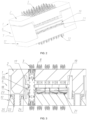
FIG. 1 is a perspective exploded view of one embodiment of the connector with the tolerance module in the present invention; -
FIG. 2 is a perspective view of the plugged state of the plug and the socket inFIG. 1 ; -
FIG. 3 is a sectional view ofFIG. 2 (the second contact members are only partially shown); -
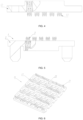
FIG. 4 is a schematic structural diagram of a connection module corresponding to the third housing inFIG. 3 ; -
FIG. 5 is a schematic structural diagram of the plug corresponding to the first housing inFIG. 3 ; -
FIG. 6 is a perspective view of the supporting plate inFIG. 2 ; -
FIG. 7 is a perspective view of a PCB contact member; -
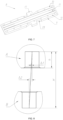
FIG. 8 is a schematic diagram of large displacement insertion; -
FIG. 9 is a schematic structural diagram of zero displacement plugging of the connector with the tolerance module; -
FIG. 10 is a schematic diagram of displacement of the connector with the tolerance module in the board interval direction of the PCB contact member; -
FIG. 11 is a schematic diagram of displacement of the connector with the tolerance module in the board extending direction of the PCB contact member; -
FIG. 12 is a schematic structural view of a first contact member and a third contact member; -
FIG. 13 to 15 are schematic diagrams of use states of other three embodiments of the connector with the tolerance module in the present invention. - In
FIG. 9 and10 , the portions of thefirst contact members 3 and thethird contact members 13 which are used for insertion fitting with thesecond contact members 8 are both represented in an unplugged state. It should be understood by those skilled in the art that when the plug and the socket are in the plugged state, the two ends of eachsecond contact member 8 are actually sandwiched between the two side contact pieces of the correspondingfirst contact member 3 and between the two side contact pieces of the correspondingthird contact member 13, and when displacement occurs in thesecond contact member 8 as shown inFIG. 10 , thefirst contact member 3 and thethird contact member 13 can be elastically deformed under the action of thesecond contact member 8. - In the drawings, the components corresponding to the corresponding reference numerals are designated as: 1-socket, 2-first housing, 3-first contact member, 4-ground pin, 5-signal pin, 6-plug, 7-second housing, 8-second contact member, 9-plate body, 10-ground contact piece, 11-signal contact piece, 12-third housing, 13-third contact member, 17-ear plate, 18-pressure plate, 19-supporting plate, 20-through hole, 21-elastic piece, 22-guide column, 23-stopping flange, 24-counterbore, 25-radial floating space, 26-groove, 27-elastic member accommodating groove, 28-reduced section.
- The present invention will be further described below with reference to the drawings.
- One embodiment of the connector with the tolerance module according to the present invention is shown in
FIG. 1 to 12 and is a differential connector, which belongs to high-density connectors. The connector is in a two-piece structure comprising a socket 1 and aplug 6 adapted to the socket 1, wherein the socket 1 comprises afirst housing 2 andfirst contact members 3, theplug 6 comprises asecond housing 7 and athird housing 12, thesecond housing 7 is internally provided withsecond contact members 8, thethird housing 12 is provided withthird contact members 13, and thesecond housing 7 and thesecond contact member 8 are used for forming the tolerance module. The formed tolerance module can play a role of leverage to reduce the displacement of the plugged part, and the adopted principle exists the prior art. As shown inFIG. 8 , taking a parallel board connection mode (i.e., the circuit board connected to theplug 6 is parallel to the circuit board connected to the socket 1) for example, the horizontal displacement of the two parallel board connectors A is Δ2, the displacement of the connector plugging position is Δ1, the length of the contact member B of the tolerance module is H, and the distance from the end of the gold finger to the port of the connector is h in the case of nominal stacking height; and according to the similar triangular principle, Δ1/Δ2=h/H, so that the actual displacement of the product during plugging can be reduced. In the present embodiment, the axial length of the second housing is less than 110mm. - The
second housing 7 is movably arranged on thethird housing 12 in a direction perpendicular to the axial direction of the connector, and thesecond contact member 8 is floatingly assembled in thesecond housing 7. Specifically, thesecond contact members 8 are PCB contact pieces, of which the structure is shown as inFIG. 7 . As a whole, thesecond contact member 8 is in a strip-shaped structure, and comprises a plate body 9. Both sides of the plate body 9 in the width direction are respectively provided withground contact pieces 10, between which asignal contact piece 11 is arranged; correspondingly, thefirst contact member 3 and thethird contact member 13 respectively comprise a ground pin 4 and asignal pin 5 arranged in the middle of the ground pin 4;ear plates 17 are arranged on both sides of the width direction of the middle of the length direction of the PCB board contact member, forming a stopping boss; Thesecond housing 7 comprises apressure plate 18 disposed on one side of the stopping boss away from thethird housing 12, and further comprises a supportingplate 19 disposed on one side of the stopping boss close to thethird housing 12, thepressure plate 18 forms a limiting seat, and the supportingplate 19 forms a supporting seat. Thepressure plate 18 comprises a plate body and connecting blocks disposed on opposite sides of the plate body, and the two connecting blocks are connected to the plate body in the middle of the axial direction of the connector. - The plate body and the supporting
plate 19 are provided with throughholes 20 through which thesecond contact members 8 pass in a floating manner, the stopping boss is sandwiched between thepressure plate 18 and the supportingplate 19, axial floating spaces are formed between the supportingplate 19 and thethird housing 12, and elastic supporting members are arranged between the supportingplate 19 and thethird housing 12, and the elastic supporting members areelastic pieces 21 uniformly fixed on the supportingplate 19.Guide columns 22 are fixed on thethird housing 12, one end of eachguide column 22 close to thesecond housing 7 is provided with astopping flange 23, thesecond housing 7 is provided withcounterbores 24, eachguide column 22 is arranged through thecorresponding counterbore 24, the annular steps of thecounterbores 24 is in stopping fit with thestopping flanges 23, and radialfloating spaces 25 are formed between the bore walls of thecounterbores 24 and the outer circumferential surfaces of thestopping flanges 23. Corresponding to thecounterbores 24, thefirst housing 2 is provided with guide posts for insertion into thecounterbores 24, the diameter of the guide posts is smaller than that of thecounterbores 24, and the ends of the guide posts are provided with guide cones, which can play a guiding role during insertion. - One side of the supporting
plate 19 away from thethird housing 12 is provided withgrooves 26 for partially embedding the stopping boss portion, and a gap is formed between one side of the supportingplate 19 away from thethird housing 12 and thepressure plate 18. One side of the supportingplate 19 close to thethird housing 12 is provided with elasticmember accommodating grooves 27 for partially embedding the elastic supporting members. - In order to ensure smooth floating of the
second contact members 8, the portion of each second contact member, which fits with the through holes on the plate body and the supporting plate, is a reduced section, and the radial dimension of the side of the reducedsection 28 that is close to the stopping boss is smaller than that of the side away from the stopping boss. - When the
plug 6 and the socket 1 of the connector are plugged to each other, thesecond housing 7 and thethird housing 12 can move in a direction perpendicular to the axial direction of the connector, i.e. thesecond housing 7 is only capable of translating relative to thethird housing 12 in a direction perpendicular to the axial direction of the connector. - Meanwhile, due to the fact of being floatingly assembled in the
second housing 7, eachsecond contact member 8 can displace in the same manner during plugging, thereby achieving tolerance. Of course, in order to ensure that thesecond housing 7 and thethird housing 12 can move smoothly, the above-mentioned "movement in a direction perpendicular to the axial direction of the connector" does not mean that thesecond housing 7 and thethird housing 12 are completely tightly attached in the axial direction of the connector, and a small axial gap may be formed there between only to ensure that thesecond housing 7 and thethird housing 12 can translate relative to each other but not to provide a floating space. - In the above-described embodiment, the
second contact members 8 are elastically supported on thesecond housing 7 through the elastic supporting members. - In the above-described embodiment, the
second contact members 8 are provided with a stopping boss in the middle of the length direction, and in other embodiments, the stopping boss can be provided at a position close to the ends of thesecond contact members 8. Besides, in the above embodiment, the limiting seat is apressure plate 18, the supporting seat is a supportingplate 19, and the plate body of thepressing plate 18 is in the middle of the limiting seat. In other embodiments, the limiting seat and the supporting seat can also be replaced with other forms such as a block structure, and the fitting position of thepressure plate 18 and thesecond contact member 8 can also be disposed on the side of thesecond housing 7 close to or away from thethird housing 12. - In the above-described embodiment, the
second housing 7 and thethird housing 12 are movably arranged in a direction perpendicular to the axial direction of the connector by means ofguide columns 22 fixed to thethird housing 12, and in other embodiments, theguide columns 22 may also be arranged on thesecond housing 7. In addition, in other embodiments, theguide post 22 may also be replaced with other forms, for example, screws, which can achieve axial limitation through the screw heads. - In the above-described embodiment, the
second contact members 8 are PCB contact members, and in other embodiments, thesecond contact members 8 can be replaced with another form such as columnar contact members. - In the above-described embodiment, the connector is used as a parallel board connector, and in other embodiments, the connector can also be used on other occasions such as a backplane connector in the prior art (as shown in
FIG. 13 , in which two mutually perpendicular printed boards 200 are respectively provided with an L-shaped board end connector 201 and a straight board end connector 202, one of the two printed boards 200 is parallel to the plugging direction of the connector, the other is perpendicular to the plugging direction of the connector, the plugging portions of the L-shaped board end connector 201 and the straight board end connector 202 are arranged opposite to each other, a tolerance module 203 is arranged between the plugging portions of the L-shaped board end connector 201 and the straight board end connector 202, and the structures of the plugging portion of the L-shaped board end connector 201, the plugging portion of the straight board end connector 202 and the tolerance module 203 are the same as those in the first embodiment), a common panel connector used in the prior art (as shown inFIG. 14 , in which two coplanar printed boards 300 are respectively provided with an L-shaped board end connector 301 and are both parallel to the plugging direction of the connector, the plugging portions of the two L-shaped board end connectors 301 are arranged opposite to each other, a tolerance module 302 is arranged between the two L-shaped board end connectors 301, and the structures of the plugging portions of the two L-shaped board end connectors 301 and the tolerance module 302 are the same as those in the first embodiment) and an orthogonal board connector used in the prior art (as shown inFIG. 15 , in which two mutually perpendicular printed boards 400 are respectively provided with an L-shaped board end connector 401 and are both parallel to the plugging direction of the connector, the plugging portions of the two L-shaped board end connectors 401 are arranged opposite to each other, a tolerance module 402 is arranged between the two L-shaped board end connectors 401, and the structure of the plugging portions of the two L-shaped board end connectors 401 and the tolerance module 402 are the same as those in the first embodiment).
Claims (9)
- A connector with a tolerance module, comprising a socket(1) and a plug(6) adapted to the socket(1), the socket(1) comprising a first housing(2), the plug(6) comprising a tolerance module and a third housing(12), the tolerance module comprising a second housing(7), the second housing(7) being internally provided with second contact members(8), the second housing(7) is movably arranged on the third housing(12) in a direction perpendicular to an axial direction of the connector, and the second contact member(8) is floatingly assembled in the second housing(7) to enable displacement in the direction perpendicular to the axial direction of the connector; the second contact members(8) are provided with a stopping boss (17), characterized in that the second housing(7) comprises a limiting seat (18) disposed on one side of the stopping boss away from the third housing(12), a supporting seat (19) is disposed on one side of the stopping boss away from the limiting seat, through holes(20) for allowing the second contact members(8) to pass through in a floating manner are formed in the limiting seat and the supporting seat, and the stopping boss is limited between the limiting seat and the supporting seat, the supporting seat and the limiting seat are separately arranged, an axially floating space is formed between the supporting seat and the third housing, elastic supporting members are arranged between the supporting seat and the third housing(12), and the supporting seat is elastically supported on the stopping boss of the second contact members(8) by means of the elastic supporting members (21), the elastic supporting members are elastic pieces(21) uniformly fixed on the supporting seat, one side of the supporting seat close to the third housing(12) is provided with elastic member accommodating grooves(27) for partially embedding the elastic supporting members.
- The connector with a tolerance module according to claim 1, characterized in that the limiting seat comprises a plate body and two connecting blocks disposed on opposite sides of the plate body, wherein the two connecting blocks are connected to the plate body in the middle of the axial direction of the connector, and the second contact members(8) penetrate through the plate body.
- The connector with a tolerance module according to claim 1, characterized in that the stopping boss is disposed in the middle of the second contact members(8) along a length direction of the second contact member(8).
- The connector with a tolerance module according to claim 3, characterized in that the supporting seat is a supporting plate(19), the portion of each second contact member(8), which fits with the through holes(20) on the plate body and the supporting plate(19), is a reduced section(28), and radial dimension of the side of the reduced section that is close to the stopping boss is smaller than that of the side away from the stopping boss.
- The connector with a tolerance module according to claim 1, characterized in that one side of the supporting seat away from the third housing(12) is provided with a groove(26) for partially embedding the stopping boss, and a gap is formed between one side of the supporting seat away from the third housing(12) and the limiting seat.
- The connector with a tolerance module according to claim 1, characterized in that the second contact members(8) are PCB contact members, and the stopping boss is formed by an ear boards(17) disposed in a width direction and on both sides of each PCB contact member.
- The connector with a tolerance module according to claim 1, characterized in that guide columns(22) are fixed on the third housing(12), one end of each guide column(22) close to the second housing(7) is provided with a stopping flange(23), the second housing(7) is provided with counterbores(24), the guide columns pass through the counterbores(24), the counterbores(24) have annular steps and bore walls, the stopping flanges(23) have outer circumferential surfaces, and the annular steps of the counterbores(24) are engaged with the stopping flange(23), and radial floating spaces are provided between the bore walls of the counterbores(24) and the outer circumferential surfaces of the stopping flanges(23).
- The connector with a tolerance module according to claim 7, characterized in that the first housing(2) is provided with guide posts for insertion into the counterbores(24), and the diameter of the guide posts is smaller than that of the counterbores(24).
- A connector with a tolerance module according to claim 1, characterized in that the length of the second housing(7) in the axial direction is less than 110mm
Applications Claiming Priority (3)
| Application Number | Priority Date | Filing Date | Title |
|---|---|---|---|
| CN201710918944 | 2017-09-30 | ||
| CN201810847131.1A CN109616799B (en) | 2017-09-30 | 2018-07-27 | Connector with tolerance module |
| PCT/CN2019/097417 WO2020020201A1 (en) | 2017-09-30 | 2019-07-24 | Connector having tolerance module |
Publications (4)
| Publication Number | Publication Date |
|---|---|
| EP3793035A1 EP3793035A1 (en) | 2021-03-17 |
| EP3793035A4 EP3793035A4 (en) | 2022-01-26 |
| EP3793035C0 EP3793035C0 (en) | 2024-02-28 |
| EP3793035B1 true EP3793035B1 (en) | 2024-02-28 |
Family
ID=65956512
Family Applications (1)
| Application Number | Title | Priority Date | Filing Date |
|---|---|---|---|
| EP19841120.9A Active EP3793035B1 (en) | 2017-09-30 | 2019-07-24 | Connector having tolerance module |
Country Status (4)
| Country | Link |
|---|---|
| US (1) | US11695227B2 (en) |
| EP (1) | EP3793035B1 (en) |
| CN (6) | CN109599690B (en) |
| WO (1) | WO2020020201A1 (en) |
Families Citing this family (23)
| Publication number | Priority date | Publication date | Assignee | Title |
|---|---|---|---|---|
| CN109599690B (en) | 2017-09-30 | 2021-01-29 | 中航光电科技股份有限公司 | Adaptor connector and electric connector assembly |
| CN110459919B (en) * | 2018-06-29 | 2022-01-25 | 中航光电科技股份有限公司 | Differential connector and differential pair shielding structure and shielding buckle plate thereof |
| CN109659722B (en) * | 2018-07-27 | 2021-02-05 | 中航光电科技股份有限公司 | Connector assembly |
| WO2021062865A1 (en) * | 2019-10-02 | 2021-04-08 | Shanghai Radiall Electronics Co., Ltd. | Unitary rf connector with ground contact tabs arranged in crown and ganged connector including a plurality of such unitary connector |
| JP7226260B2 (en) * | 2019-11-13 | 2023-02-21 | 株式会社オートネットワーク技術研究所 | connector device |
| CN113115527B (en) * | 2020-01-13 | 2023-01-03 | 中移物联网有限公司 | Data transmission unit |
| US20230170636A1 (en) * | 2020-05-01 | 2023-06-01 | Molex, Llc | Floating socket connector |
| CN113745905B (en) * | 2020-05-29 | 2024-03-29 | 庆虹电子(苏州)有限公司 | Connector device and connector floating module |
| CN111952764B (en) * | 2020-06-22 | 2022-04-22 | 中航光电科技股份有限公司 | Connectors and Connector Assemblies |
| CN112787161B (en) * | 2021-01-20 | 2026-02-03 | 中航光电科技股份有限公司 | Floating socket and floating connector |
| CN114530733B (en) * | 2021-02-09 | 2024-04-16 | 中航光电科技股份有限公司 | Differential signal connector assembly for vertical interconnection between printed boards |
| US11831093B2 (en) * | 2021-03-30 | 2023-11-28 | Cisco Technology, Inc. | Socket locator |
| CN113346272A (en) * | 2021-05-20 | 2021-09-03 | 东莞市鼎通精密科技股份有限公司 | Circular contact pin communication connector |
| CN113381229B (en) * | 2021-06-09 | 2022-03-18 | 深圳市爱得乐电子有限公司 | High-density signal transmission connector |
| CN114204318B (en) * | 2021-12-10 | 2024-01-23 | 四川华丰科技股份有限公司 | Anti-collision connector |
| CN114361835A (en) * | 2021-12-15 | 2022-04-15 | 上海航天科工电器研究院有限公司 | High transmission rate connector |
| CN114498120A (en) * | 2022-01-28 | 2022-05-13 | 浩亭(珠海)制造有限公司 | High-density high-expansibility connection adapter |
| CN115425468B (en) * | 2022-08-22 | 2025-08-05 | 中航光电科技股份有限公司 | Multi-point adaptation structure |
| CN115603075B (en) * | 2022-09-22 | 2026-06-12 | 中航光电科技股份有限公司 | Radio frequency switching printed board |
| CN116037348B (en) * | 2022-12-27 | 2025-11-21 | 广东新会中集特种运输设备有限公司 | Anti-pollution device and anti-pollution method for coating cavity workpiece with door end |
| CN118572448B (en) * | 2024-06-04 | 2025-03-11 | 深圳尼索科连接技术有限公司 | Floating plugs and floating connectors |
| CN118508121B (en) * | 2024-07-18 | 2024-10-29 | 宁波吉品科技有限公司 | Millimeter wave power assembly connection structure |
| CN119627522B (en) * | 2024-11-20 | 2025-10-28 | 成都宏明电子股份有限公司 | Detachable filter electric connector |
Family Cites Families (53)
| Publication number | Priority date | Publication date | Assignee | Title |
|---|---|---|---|---|
| JPH0675415B2 (en) * | 1991-03-15 | 1994-09-21 | 山一電機株式会社 | Leadless type IC package connector |
| JP3007812U (en) * | 1994-05-25 | 1995-02-28 | モレックス インコーポレーテッド | Surface mount electrical connector |
| US6267604B1 (en) * | 2000-02-03 | 2001-07-31 | Tyco Electronics Corporation | Electrical connector including a housing that holds parallel circuit boards |
| JP2002093502A (en) * | 2000-09-14 | 2002-03-29 | Fujitsu Ten Ltd | Floating connector |
| GB2372878B (en) * | 2001-03-03 | 2004-12-08 | Visteon Global Tech Inc | Component carrier |
| US6695622B2 (en) * | 2002-05-31 | 2004-02-24 | Hon Hai Precision Ind. Co., Ltd. | Electrical system having means for accommodating various distances between PC boards thereof mounting the means |
| JP4265892B2 (en) * | 2002-08-06 | 2009-05-20 | インターナショナル・ビジネス・マシーンズ・コーポレーション | Connector device |
| EP2063499A3 (en) * | 2002-09-19 | 2009-11-11 | Sumitomo Wiring Systems, Ltd. | A connector assembly, connector, connector assembling construction and method of assembling them |
| US6699054B1 (en) * | 2003-01-15 | 2004-03-02 | Applied Engineering Products, Inc. | Float mount coaxial connector |
| JP2005026213A (en) * | 2003-06-12 | 2005-01-27 | Yamaichi Electronics Co Ltd | Method for arranging socket on substrate and socket using the method |
| US7044748B2 (en) * | 2003-09-26 | 2006-05-16 | Hon Hai Precision Ind. Co., Ltd | Electrical device for interconnecting two printed circuit boards at a large distance |
| US7234950B1 (en) * | 2006-04-26 | 2007-06-26 | Robert Bosch Gmbh | Electrical connector assembly |
| US7713088B2 (en) * | 2006-10-05 | 2010-05-11 | Fci | Broadside-coupled signal pair configurations for electrical connectors |
| US7708569B2 (en) * | 2006-10-30 | 2010-05-04 | Fci Americas Technology, Inc. | Broadside-coupled signal pair configurations for electrical connectors |
| CN201075456Y (en) * | 2007-08-03 | 2008-06-18 | 番禺得意精密电子工业有限公司 | Connector |
| US7445467B1 (en) * | 2007-11-29 | 2008-11-04 | Hirose Electric Co., Ltd. | Board electrical connector, and electrical connector assembly having board electrical connector and middle electrical connector |
| CN101488611B (en) * | 2009-02-24 | 2011-10-05 | 中航光电科技股份有限公司 | A signal connector, plug and contact piece for printed board |
| CN101540445B (en) * | 2009-04-10 | 2011-06-01 | 中航光电科技股份有限公司 | A connector and its plug |
| JP2011060732A (en) * | 2009-09-14 | 2011-03-24 | Japan Aviation Electronics Industry Ltd | Connector |
| CN102714385B (en) * | 2010-01-25 | 2014-12-03 | 胡贝尔和茹纳股份公司 | PCB Coaxial Connector |
| CN102201624B (en) * | 2010-03-26 | 2014-02-26 | 3M创新有限公司 | Electric connector and electric connector assembly |
| FR2966289A1 (en) * | 2010-10-19 | 2012-04-20 | Radiall Sa | INTERCONNECTION SYSTEM BETWEEN ELECTRONIC CARDS. |
| US8465312B2 (en) * | 2010-12-07 | 2013-06-18 | Centipede Systems, Inc. | Socket cartridge and socket cartridge assembly |
| US8425236B2 (en) * | 2011-05-16 | 2013-04-23 | International Business Machines Corporation | Tall mezzanine connector |
| JP5801125B2 (en) * | 2011-07-14 | 2015-10-28 | 日本航空電子工業株式会社 | Floating connector |
| JP5462231B2 (en) * | 2011-10-24 | 2014-04-02 | ヒロセ電機株式会社 | Electrical connector assembly |
| US8888519B2 (en) * | 2012-05-31 | 2014-11-18 | Cinch Connectivity Solutions, Inc. | Modular RF connector system |
| US9735521B2 (en) * | 2013-01-09 | 2017-08-15 | Amphenol Corporation | Float adapter for electrical connector |
| US9356374B2 (en) * | 2013-01-09 | 2016-05-31 | Amphenol Corporation | Float adapter for electrical connector |
| US9039433B2 (en) * | 2013-01-09 | 2015-05-26 | Amphenol Corporation | Electrical connector assembly with high float bullet adapter |
| CN104167628A (en) * | 2013-05-16 | 2014-11-26 | 鸿富锦精密工业(深圳)有限公司 | Connector combination unit |
| JP5840649B2 (en) * | 2013-05-29 | 2016-01-06 | ヒロセ電機株式会社 | Electrical connector, electrical connector assembly having electrical connector and mating connector |
| CN103337733B (en) | 2013-06-05 | 2016-02-10 | 四川华丰企业集团有限公司 | A kind of radio frequency (RF) coaxial connector |
| DE202013006067U1 (en) * | 2013-07-05 | 2013-08-12 | Rosenberger Hochfrequenztechnik Gmbh & Co. Kg | Connectors |
| JP6190202B2 (en) * | 2013-08-06 | 2017-08-30 | ヒロセ電機株式会社 | Electrical connector |
| JP5946804B2 (en) * | 2013-08-09 | 2016-07-06 | ヒロセ電機株式会社 | connector |
| US9042764B2 (en) * | 2013-09-12 | 2015-05-26 | Kabushiki Kaisha Toshiba | Power supply apparatus interlocked with attaching and detaching operation of unit |
| TWI614947B (en) * | 2013-11-13 | 2018-02-11 | Iriso Electronics Co Ltd | Electrical connector |
| CN104332735A (en) * | 2014-08-20 | 2015-02-04 | 中航光电科技股份有限公司 | Bidirectional floating adapter and adapting contact assembly thereof |
| CN104332760B (en) * | 2014-08-29 | 2017-08-04 | 中航光电科技股份有限公司 | Floating contact piece, connector and connector assembly using the floating contact piece |
| CN104319508A (en) * | 2014-08-29 | 2015-01-28 | 中航光电科技股份有限公司 | B-shaped elastic contact piece and electric connector employing same |
| CN204577732U (en) * | 2015-03-31 | 2015-08-19 | 昆山西威联电气系统有限公司 | A kind of float connector |
| US9337577B1 (en) * | 2015-03-31 | 2016-05-10 | Tyco Electronics Corporation | Floatable connector |
| CN204809560U (en) * | 2015-06-10 | 2015-11-25 | 泰科电子(上海)有限公司 | Connector module and connector component |
| CN205543466U (en) * | 2016-01-27 | 2016-08-31 | 浙江德利接插件有限公司 | Female socket of connector |
| CN205790554U (en) * | 2016-05-27 | 2016-12-07 | 深圳市深台帏翔电子有限公司 | Adapter |
| CN105896145B (en) * | 2016-05-27 | 2018-05-08 | 深圳市深台帏翔电子有限公司 | Connector |
| CN106129743B (en) * | 2016-06-24 | 2018-11-13 | 中航光电科技股份有限公司 | Connector assembly and its switching part and socket |
| US9748698B1 (en) * | 2016-06-30 | 2017-08-29 | Te Connectivity Corporation | Electrical connector having commoned ground shields |
| US9614309B1 (en) * | 2016-07-07 | 2017-04-04 | Hirose Electric Co., Ltd. | Electrical connector assembly |
| JP2018022629A (en) * | 2016-08-04 | 2018-02-08 | 日本圧着端子製造株式会社 | Connector member and connector |
| CN109599690B (en) | 2017-09-30 | 2021-01-29 | 中航光电科技股份有限公司 | Adaptor connector and electric connector assembly |
| CN108072938B (en) * | 2017-12-04 | 2020-04-07 | 中航光电科技股份有限公司 | Floating type optical fiber contact element and connector thereof |
-
2018
- 2018-07-27 CN CN201810847128.XA patent/CN109599690B/en active Active
- 2018-07-27 CN CN201810845135.6A patent/CN109599689B/en active Active
- 2018-07-27 CN CN201810847131.1A patent/CN109616799B/en active Active
- 2018-07-27 CN CN201810845133.7A patent/CN109616790B/en active Active
- 2018-07-27 CN CN201810845128.6A patent/CN109599729B/en active Active
- 2018-07-27 CN CN201810845129.0A patent/CN109616810B/en active Active
-
2019
- 2019-07-24 EP EP19841120.9A patent/EP3793035B1/en active Active
- 2019-07-24 US US17/044,618 patent/US11695227B2/en active Active
- 2019-07-24 WO PCT/CN2019/097417 patent/WO2020020201A1/en not_active Ceased
Also Published As
| Publication number | Publication date |
|---|---|
| CN109599729A (en) | 2019-04-09 |
| CN109599690B (en) | 2021-01-29 |
| EP3793035C0 (en) | 2024-02-28 |
| CN109599729B (en) | 2021-01-29 |
| CN109599689A (en) | 2019-04-09 |
| CN109616810A (en) | 2019-04-12 |
| CN109616810B (en) | 2021-01-29 |
| US11695227B2 (en) | 2023-07-04 |
| EP3793035A1 (en) | 2021-03-17 |
| WO2020020201A1 (en) | 2020-01-30 |
| CN109616799A (en) | 2019-04-12 |
| CN109599689B (en) | 2020-11-17 |
| EP3793035A4 (en) | 2022-01-26 |
| CN109599690A (en) | 2019-04-09 |
| CN109616799B (en) | 2021-01-29 |
| CN109616790A (en) | 2019-04-12 |
| CN109616790B (en) | 2020-11-17 |
| US20210075134A1 (en) | 2021-03-11 |
Similar Documents
| Publication | Publication Date | Title |
|---|---|---|
| US11695227B2 (en) | Connector with tolerance module | |
| US7255578B2 (en) | Two-dimensional adjustable edge connector adaptor | |
| US9084340B2 (en) | Electronic device unit and electronic device | |
| US8292644B2 (en) | Connector assembly having a floating mating array | |
| EP3467950B1 (en) | Connector | |
| US8342866B2 (en) | Connector assemblies having mating sides moved by fluidic coupling mechanisms | |
| CN116154525B (en) | Connector socket | |
| WO2013012680A1 (en) | An electrical connector | |
| CN208890023U (en) | Radio frequency (RF) coaxial connector | |
| TWI832578B (en) | Thinned connecting module, thinning method of connecting module, and electronic device | |
| CN213584306U (en) | High-speed signal transmission connector | |
| CN112003050B (en) | Exchange board assembly and box having the same | |
| CN223379442U (en) | Cable backboard and communication equipment | |
| WO2021114786A1 (en) | Plug-in structure and device interconnection system | |
| CN220985005U (en) | Misplug preventing connector | |
| CN223402663U (en) | Panel, cable backplane housing and cable backplane | |
| CN223310107U (en) | Cable backplane housing and cable backplane | |
| CN110829065B (en) | Floating orientation support and electronic assembly | |
| CN110994949B (en) | Power module installed part and module power | |
| CN222463647U (en) | Floating high-speed connector | |
| CN222654494U (en) | Computing equipment | |
| CN221447548U (en) | Rectangular electric connector structure | |
| CN222515076U (en) | Connector assembly and cabin electronic equipment | |
| CN223471842U (en) | Computing device and connector assembly | |
| US8721189B2 (en) | Optical fiber connector assembly |
Legal Events
| Date | Code | Title | Description |
|---|---|---|---|
| STAA | Information on the status of an ep patent application or granted ep patent |
Free format text: STATUS: THE INTERNATIONAL PUBLICATION HAS BEEN MADE |
|
| PUAI | Public reference made under article 153(3) epc to a published international application that has entered the european phase |
Free format text: ORIGINAL CODE: 0009012 |
|
| STAA | Information on the status of an ep patent application or granted ep patent |
Free format text: STATUS: REQUEST FOR EXAMINATION WAS MADE |
|
| 17P | Request for examination filed |
Effective date: 20201210 |
|
| AK | Designated contracting states |
Kind code of ref document: A1 Designated state(s): AL AT BE BG CH CY CZ DE DK EE ES FI FR GB GR HR HU IE IS IT LI LT LU LV MC MK MT NL NO PL PT RO RS SE SI SK SM TR |
|
| AX | Request for extension of the european patent |
Extension state: BA ME |
|
| DAV | Request for validation of the european patent (deleted) | ||
| DAX | Request for extension of the european patent (deleted) | ||
| A4 | Supplementary search report drawn up and despatched |
Effective date: 20220104 |
|
| RIC1 | Information provided on ipc code assigned before grant |
Ipc: H01R 12/58 20110101ALN20211221BHEP Ipc: H01R 13/6471 20110101ALN20211221BHEP Ipc: H01R 12/73 20110101ALN20211221BHEP Ipc: H01R 13/66 20060101ALN20211221BHEP Ipc: H01R 12/71 20110101ALI20211221BHEP Ipc: H01R 12/70 20110101ALI20211221BHEP Ipc: H05K 1/00 20060101ALI20211221BHEP Ipc: H01R 12/91 20110101AFI20211221BHEP |
|
| STAA | Information on the status of an ep patent application or granted ep patent |
Free format text: STATUS: EXAMINATION IS IN PROGRESS |
|
| 17Q | First examination report despatched |
Effective date: 20230925 |
|
| GRAP | Despatch of communication of intention to grant a patent |
Free format text: ORIGINAL CODE: EPIDOSNIGR1 |
|
| STAA | Information on the status of an ep patent application or granted ep patent |
Free format text: STATUS: GRANT OF PATENT IS INTENDED |
|
| RIC1 | Information provided on ipc code assigned before grant |
Ipc: H05K 1/14 20060101ALN20231129BHEP Ipc: H01R 12/58 20110101ALN20231129BHEP Ipc: H01R 13/6471 20110101ALN20231129BHEP Ipc: H01R 12/73 20110101ALN20231129BHEP Ipc: H01R 13/66 20060101ALN20231129BHEP Ipc: H05K 1/18 20060101ALI20231129BHEP Ipc: H01R 12/71 20110101ALI20231129BHEP Ipc: H01R 12/70 20110101ALI20231129BHEP Ipc: H05K 1/11 20060101ALI20231129BHEP Ipc: H01R 12/91 20110101AFI20231129BHEP |
|
| RIC1 | Information provided on ipc code assigned before grant |
Ipc: H05K 1/14 20060101ALN20231207BHEP Ipc: H01R 12/58 20110101ALN20231207BHEP Ipc: H01R 13/6471 20110101ALN20231207BHEP Ipc: H01R 12/73 20110101ALN20231207BHEP Ipc: H01R 13/66 20060101ALN20231207BHEP Ipc: H05K 1/18 20060101ALI20231207BHEP Ipc: H01R 12/71 20110101ALI20231207BHEP Ipc: H01R 12/70 20110101ALI20231207BHEP Ipc: H05K 1/11 20060101ALI20231207BHEP Ipc: H01R 12/91 20110101AFI20231207BHEP |
|
| INTG | Intention to grant announced |
Effective date: 20231219 |
|
| GRAS | Grant fee paid |
Free format text: ORIGINAL CODE: EPIDOSNIGR3 |
|
| GRAA | (expected) grant |
Free format text: ORIGINAL CODE: 0009210 |
|
| STAA | Information on the status of an ep patent application or granted ep patent |
Free format text: STATUS: THE PATENT HAS BEEN GRANTED |
|
| AK | Designated contracting states |
Kind code of ref document: B1 Designated state(s): AL AT BE BG CH CY CZ DE DK EE ES FI FR GB GR HR HU IE IS IT LI LT LU LV MC MK MT NL NO PL PT RO RS SE SI SK SM TR |
|
| REG | Reference to a national code |
Ref country code: GB Ref legal event code: FG4D |
|
| REG | Reference to a national code |
Ref country code: CH Ref legal event code: EP |
|
| REG | Reference to a national code |
Ref country code: DE Ref legal event code: R096 Ref document number: 602019047467 Country of ref document: DE |
|
| REG | Reference to a national code |
Ref country code: IE Ref legal event code: FG4D |
|
| U01 | Request for unitary effect filed |
Effective date: 20240321 |
|
| U07 | Unitary effect registered |
Designated state(s): AT BE BG DE DK EE FI FR IT LT LU LV MT NL PT SE SI Effective date: 20240402 |
|
| PG25 | Lapsed in a contracting state [announced via postgrant information from national office to epo] |
Ref country code: IS Free format text: LAPSE BECAUSE OF FAILURE TO SUBMIT A TRANSLATION OF THE DESCRIPTION OR TO PAY THE FEE WITHIN THE PRESCRIBED TIME-LIMIT Effective date: 20240628 |
|
| PG25 | Lapsed in a contracting state [announced via postgrant information from national office to epo] |
Ref country code: GR Free format text: LAPSE BECAUSE OF FAILURE TO SUBMIT A TRANSLATION OF THE DESCRIPTION OR TO PAY THE FEE WITHIN THE PRESCRIBED TIME-LIMIT Effective date: 20240529 |
|
| PG25 | Lapsed in a contracting state [announced via postgrant information from national office to epo] |
Ref country code: HR Free format text: LAPSE BECAUSE OF FAILURE TO SUBMIT A TRANSLATION OF THE DESCRIPTION OR TO PAY THE FEE WITHIN THE PRESCRIBED TIME-LIMIT Effective date: 20240228 Ref country code: RS Free format text: LAPSE BECAUSE OF FAILURE TO SUBMIT A TRANSLATION OF THE DESCRIPTION OR TO PAY THE FEE WITHIN THE PRESCRIBED TIME-LIMIT Effective date: 20240528 |
|
| PG25 | Lapsed in a contracting state [announced via postgrant information from national office to epo] |
Ref country code: ES Free format text: LAPSE BECAUSE OF FAILURE TO SUBMIT A TRANSLATION OF THE DESCRIPTION OR TO PAY THE FEE WITHIN THE PRESCRIBED TIME-LIMIT Effective date: 20240228 |
|
| PG25 | Lapsed in a contracting state [announced via postgrant information from national office to epo] |
Ref country code: RS Free format text: LAPSE BECAUSE OF FAILURE TO SUBMIT A TRANSLATION OF THE DESCRIPTION OR TO PAY THE FEE WITHIN THE PRESCRIBED TIME-LIMIT Effective date: 20240528 Ref country code: NO Free format text: LAPSE BECAUSE OF FAILURE TO SUBMIT A TRANSLATION OF THE DESCRIPTION OR TO PAY THE FEE WITHIN THE PRESCRIBED TIME-LIMIT Effective date: 20240528 Ref country code: IS Free format text: LAPSE BECAUSE OF FAILURE TO SUBMIT A TRANSLATION OF THE DESCRIPTION OR TO PAY THE FEE WITHIN THE PRESCRIBED TIME-LIMIT Effective date: 20240628 Ref country code: HR Free format text: LAPSE BECAUSE OF FAILURE TO SUBMIT A TRANSLATION OF THE DESCRIPTION OR TO PAY THE FEE WITHIN THE PRESCRIBED TIME-LIMIT Effective date: 20240228 Ref country code: GR Free format text: LAPSE BECAUSE OF FAILURE TO SUBMIT A TRANSLATION OF THE DESCRIPTION OR TO PAY THE FEE WITHIN THE PRESCRIBED TIME-LIMIT Effective date: 20240529 Ref country code: ES Free format text: LAPSE BECAUSE OF FAILURE TO SUBMIT A TRANSLATION OF THE DESCRIPTION OR TO PAY THE FEE WITHIN THE PRESCRIBED TIME-LIMIT Effective date: 20240228 |
|
| PG25 | Lapsed in a contracting state [announced via postgrant information from national office to epo] |
Ref country code: PL Free format text: LAPSE BECAUSE OF FAILURE TO SUBMIT A TRANSLATION OF THE DESCRIPTION OR TO PAY THE FEE WITHIN THE PRESCRIBED TIME-LIMIT Effective date: 20240228 |
|
| PG25 | Lapsed in a contracting state [announced via postgrant information from national office to epo] |
Ref country code: PL Free format text: LAPSE BECAUSE OF FAILURE TO SUBMIT A TRANSLATION OF THE DESCRIPTION OR TO PAY THE FEE WITHIN THE PRESCRIBED TIME-LIMIT Effective date: 20240228 |
|
| U20 | Renewal fee for the european patent with unitary effect paid |
Year of fee payment: 6 Effective date: 20240726 |
|
| PG25 | Lapsed in a contracting state [announced via postgrant information from national office to epo] |
Ref country code: SM Free format text: LAPSE BECAUSE OF FAILURE TO SUBMIT A TRANSLATION OF THE DESCRIPTION OR TO PAY THE FEE WITHIN THE PRESCRIBED TIME-LIMIT Effective date: 20240228 |
|
| PG25 | Lapsed in a contracting state [announced via postgrant information from national office to epo] |
Ref country code: CZ Free format text: LAPSE BECAUSE OF FAILURE TO SUBMIT A TRANSLATION OF THE DESCRIPTION OR TO PAY THE FEE WITHIN THE PRESCRIBED TIME-LIMIT Effective date: 20240228 |
|
| PG25 | Lapsed in a contracting state [announced via postgrant information from national office to epo] |
Ref country code: SK Free format text: LAPSE BECAUSE OF FAILURE TO SUBMIT A TRANSLATION OF THE DESCRIPTION OR TO PAY THE FEE WITHIN THE PRESCRIBED TIME-LIMIT Effective date: 20240228 |
|
| PG25 | Lapsed in a contracting state [announced via postgrant information from national office to epo] |
Ref country code: SM Free format text: LAPSE BECAUSE OF FAILURE TO SUBMIT A TRANSLATION OF THE DESCRIPTION OR TO PAY THE FEE WITHIN THE PRESCRIBED TIME-LIMIT Effective date: 20240228 Ref country code: SK Free format text: LAPSE BECAUSE OF FAILURE TO SUBMIT A TRANSLATION OF THE DESCRIPTION OR TO PAY THE FEE WITHIN THE PRESCRIBED TIME-LIMIT Effective date: 20240228 Ref country code: RO Free format text: LAPSE BECAUSE OF FAILURE TO SUBMIT A TRANSLATION OF THE DESCRIPTION OR TO PAY THE FEE WITHIN THE PRESCRIBED TIME-LIMIT Effective date: 20240228 Ref country code: CZ Free format text: LAPSE BECAUSE OF FAILURE TO SUBMIT A TRANSLATION OF THE DESCRIPTION OR TO PAY THE FEE WITHIN THE PRESCRIBED TIME-LIMIT Effective date: 20240228 |
|
| REG | Reference to a national code |
Ref country code: DE Ref legal event code: R097 Ref document number: 602019047467 Country of ref document: DE |
|
| PLBE | No opposition filed within time limit |
Free format text: ORIGINAL CODE: 0009261 |
|
| STAA | Information on the status of an ep patent application or granted ep patent |
Free format text: STATUS: NO OPPOSITION FILED WITHIN TIME LIMIT |
|
| 26N | No opposition filed |
Effective date: 20241129 |
|
| PG25 | Lapsed in a contracting state [announced via postgrant information from national office to epo] |
Ref country code: MC Free format text: LAPSE BECAUSE OF FAILURE TO SUBMIT A TRANSLATION OF THE DESCRIPTION OR TO PAY THE FEE WITHIN THE PRESCRIBED TIME-LIMIT Effective date: 20240228 |
|
| REG | Reference to a national code |
Ref country code: CH Ref legal event code: PL |
|
| GBPC | Gb: european patent ceased through non-payment of renewal fee |
Effective date: 20240724 |
|
| PG25 | Lapsed in a contracting state [announced via postgrant information from national office to epo] |
Ref country code: CH Free format text: LAPSE BECAUSE OF NON-PAYMENT OF DUE FEES Effective date: 20240731 |
|
| PG25 | Lapsed in a contracting state [announced via postgrant information from national office to epo] |
Ref country code: GB Free format text: LAPSE BECAUSE OF NON-PAYMENT OF DUE FEES Effective date: 20240724 |
|
| PG25 | Lapsed in a contracting state [announced via postgrant information from national office to epo] |
Ref country code: IE Free format text: LAPSE BECAUSE OF NON-PAYMENT OF DUE FEES Effective date: 20240724 |
|
| U20 | Renewal fee for the european patent with unitary effect paid |
Year of fee payment: 7 Effective date: 20250729 |
|
| PG25 | Lapsed in a contracting state [announced via postgrant information from national office to epo] |
Ref country code: CY Free format text: LAPSE BECAUSE OF FAILURE TO SUBMIT A TRANSLATION OF THE DESCRIPTION OR TO PAY THE FEE WITHIN THE PRESCRIBED TIME-LIMIT; INVALID AB INITIO Effective date: 20190724 |
|
| PG25 | Lapsed in a contracting state [announced via postgrant information from national office to epo] |
Ref country code: HU Free format text: LAPSE BECAUSE OF FAILURE TO SUBMIT A TRANSLATION OF THE DESCRIPTION OR TO PAY THE FEE WITHIN THE PRESCRIBED TIME-LIMIT; INVALID AB INITIO Effective date: 20190724 |
|
| PG25 | Lapsed in a contracting state [announced via postgrant information from national office to epo] |
Ref country code: TR Free format text: LAPSE BECAUSE OF FAILURE TO SUBMIT A TRANSLATION OF THE DESCRIPTION OR TO PAY THE FEE WITHIN THE PRESCRIBED TIME-LIMIT Effective date: 20240228 |