EP3792893A1 - Intelligent vehicle safety decision-making method employing driving safety field - Google Patents
Intelligent vehicle safety decision-making method employing driving safety field Download PDFInfo
- Publication number
- EP3792893A1 EP3792893A1 EP18917585.4A EP18917585A EP3792893A1 EP 3792893 A1 EP3792893 A1 EP 3792893A1 EP 18917585 A EP18917585 A EP 18917585A EP 3792893 A1 EP3792893 A1 EP 3792893A1
- Authority
- EP
- European Patent Office
- Prior art keywords
- vehicle
- driving
- risk
- traffic
- safety
- Prior art date
- Legal status (The legal status is an assumption and is not a legal conclusion. Google has not performed a legal analysis and makes no representation as to the accuracy of the status listed.)
- Withdrawn
Links
Images


Classifications
-
- G—PHYSICS
- G08—SIGNALLING
- G08G—TRAFFIC CONTROL SYSTEMS
- G08G1/00—Traffic control systems for road vehicles
- G08G1/01—Detecting movement of traffic to be counted or controlled
- G08G1/0104—Measuring and analyzing of parameters relative to traffic conditions
- G08G1/0125—Traffic data processing
-
- G—PHYSICS
- G08—SIGNALLING
- G08G—TRAFFIC CONTROL SYSTEMS
- G08G1/00—Traffic control systems for road vehicles
- G08G1/09—Arrangements for giving variable traffic instructions
- G08G1/0962—Arrangements for giving variable traffic instructions having an indicator mounted inside the vehicle, e.g. giving voice messages
- G08G1/0967—Systems involving transmission of highway information, e.g. weather, speed limits
- G08G1/096708—Systems involving transmission of highway information, e.g. weather, speed limits where the received information might be used to generate an automatic action on the vehicle control
- G08G1/096725—Systems involving transmission of highway information, e.g. weather, speed limits where the received information might be used to generate an automatic action on the vehicle control where the received information generates an automatic action on the vehicle control
-
- B—PERFORMING OPERATIONS; TRANSPORTING
- B60—VEHICLES IN GENERAL
- B60W—CONJOINT CONTROL OF VEHICLE SUB-UNITS OF DIFFERENT TYPE OR DIFFERENT FUNCTION; CONTROL SYSTEMS SPECIALLY ADAPTED FOR HYBRID VEHICLES; ROAD VEHICLE DRIVE CONTROL SYSTEMS FOR PURPOSES NOT RELATED TO THE CONTROL OF A PARTICULAR SUB-UNIT
- B60W50/00—Details of control systems for road vehicle drive control not related to the control of a particular sub-unit, e.g. process diagnostic or vehicle driver interfaces
- B60W50/0097—Predicting future conditions
-
- G—PHYSICS
- G06—COMPUTING OR CALCULATING; COUNTING
- G06Q—INFORMATION AND COMMUNICATION TECHNOLOGY [ICT] SPECIALLY ADAPTED FOR ADMINISTRATIVE, COMMERCIAL, FINANCIAL, MANAGERIAL OR SUPERVISORY PURPOSES; SYSTEMS OR METHODS SPECIALLY ADAPTED FOR ADMINISTRATIVE, COMMERCIAL, FINANCIAL, MANAGERIAL OR SUPERVISORY PURPOSES, NOT OTHERWISE PROVIDED FOR
- G06Q10/00—Administration; Management
- G06Q10/06—Resources, workflows, human or project management; Enterprise or organisation planning; Enterprise or organisation modelling
- G06Q10/063—Operations research, analysis or management
- G06Q10/0635—Risk analysis of enterprise or organisation activities
-
- G—PHYSICS
- G08—SIGNALLING
- G08G—TRAFFIC CONTROL SYSTEMS
- G08G1/00—Traffic control systems for road vehicles
- G08G1/01—Detecting movement of traffic to be counted or controlled
- G08G1/0104—Measuring and analyzing of parameters relative to traffic conditions
- G08G1/0137—Measuring and analyzing of parameters relative to traffic conditions for specific applications
- G08G1/0145—Measuring and analyzing of parameters relative to traffic conditions for specific applications for active traffic flow control
-
- B—PERFORMING OPERATIONS; TRANSPORTING
- B60—VEHICLES IN GENERAL
- B60W—CONJOINT CONTROL OF VEHICLE SUB-UNITS OF DIFFERENT TYPE OR DIFFERENT FUNCTION; CONTROL SYSTEMS SPECIALLY ADAPTED FOR HYBRID VEHICLES; ROAD VEHICLE DRIVE CONTROL SYSTEMS FOR PURPOSES NOT RELATED TO THE CONTROL OF A PARTICULAR SUB-UNIT
- B60W50/00—Details of control systems for road vehicle drive control not related to the control of a particular sub-unit, e.g. process diagnostic or vehicle driver interfaces
- B60W2050/0001—Details of the control system
- B60W2050/0019—Control system elements or transfer functions
- B60W2050/0028—Mathematical models, e.g. for simulation
- B60W2050/0031—Mathematical model of the vehicle
Definitions
- the invention relates to traffic safety, in particular to a vehicle intelligent safety decision-making method based on a driving safety field.
- the research method is basically at a single correlation level, that is, taking a certain influencing factor as an independent variable, taking the change of vehicle performance index as the target value to reflect vehicle safety, and conventionally directly linking the two factors, so as to analyze the impact of this factor on vehicle safety.
- the purpose of vehicle decision-making is to ensure driving safety, thereby promoting the safety of the entire transportation system.
- the safety of the traffic system depends on the coordination between the reliability of the objective safety guarantee and the driver's perception of the performance of such reliable information. That is, the traffic safety is related to the objective safety guarantee and the driver's sense of safety. When the two are coordinated and unified, system traffic safety can be realized.
- Research on vehicle intelligent safety decision-making methods can effectively promote major changes in the automotive industry. Vehicle safety is the most important goal of intelligence.
- the present invention links the field theory knowledge with the role that the driver receives during the driving process by analyzing the indicators pursued during the driving process.
- concept of field theory in psychology Lewin proposed the principle of psychology, which is defined as a psychological field.
- Arkin RC uses the artificial potential energy field method to achieve indoor path planning and active collision avoidance for mobile robots ; Reichardt D of Daimler-Benz regards the driving environment as a map centered on an autonomous vehicle and treats each coordinate point as a charged particle to study the impact of risks on the movement of smart cars, but the study is simplified The actual environmental factors and ignoring the driver factor; Kitamura Y et al. used artificial potential energy field to study the path planning of automatic aircraft in a 3D environment, and believed that this method can solve the problem of multi-moving bodies; Wolf MT et al.
- Tang Chuanshi proposed a highway vehicle collision avoidance algorithm, which uses the idea of electric field to establish the potential energy field generated by the self-car and other cars, and conducts collision avoidance path planning research on the self-car in typical scenarios such as following, overtaking, and congestion. But the scene is simplified to a certain extent, and this algorithm is only effective for specific scenes; Tourveloudis NC et al. installed ultrasonic sensors around the mobile car to perceive the surrounding obstacles and determine the relative importance of the obstacles; Reichardt et al. The electric field model is introduced to study the collision avoidance behavior of dynamic highway unmanned vehicles. Two positive charge models are used to simulate the repulsive state of two vehicles during driving.
- the electric field force calculation formula is used to calculate the nominal electric field force and applied to the longitudinal and lateral directions.
- Control model The whole theory is relatively mature, but the driver's own decision-making is not well considered, and the coupling characteristics in the coordinated environment are ignored. Aiming at the problem that the current traffic safety model cannot fully reflect the risks caused by various traffic elements such as people, cars and roads to the traffic environment, Wang Jianqiang and others proposed the idea of driving risk field. Their model covers the problems of people, cars and roads. There are a large number of parameters, but this model only provides auxiliary decision-making for driving safety, and cannot provide accurate judgment basis for vehicle intelligent safety decision-making evaluation in complex traffic environment.
- Intelligent safety decision-making methods can better realize real-time decision-making in the driving process of vehicles, and then guide drivers to drive safely, improve road traffic safety, reduce road traffic accident rates, and improve road traffic environment.
- the invention aims to provide a vehicle intelligent safety decision-making method based on a driving safety field that can provide important means for risk identification and a theoretical method of decision information support for the intelligent management and control of the traffic system.
- the present invention provides a vehicle intelligent safety decision-making method based on a driving safety field, comprising the following steps:
- the method for acquiring the "driving risk identification model" in step 1 comprises the following steps:
- U ji represents potential energy of vehicle i at (x i , y i ) due to action of vehicle j on it; K > 0 and K is an undetermined constant; DR i represents the driver's effect factor; R i represents resistance field of vehicle i caused by rolling resistance, climbing resistance, acceleration resistance, and air resistance; R j represents the resistance field of vehicle j caused by rolling resistance, climbing resistance, acceleration resistance, and air resistance to vehicle j; M i represents equivalent mass of vehicle i; M j represents equivalent mass of vehicle j; mi is the mass of vehicle i; x i is the longitudinal displacement of vehicle i; ⁇ 1 is the longitudinal velocity of vehicle i; ⁇ i is the longitudinal acceleration of vehicle i; g is acceleration of gravity; f is the rolling resistance coefficient;
- the "physical model" in step 11 is used for describing the mechanism of driving risk, and method for establishing the physical model is as follows:
- mi is the mass of first vehicle
- m 2 is the mass of second vehicle
- U 12 is potential energy of the second vehicle under the potential energy field generated by the first vehicle
- U 21 is the potential energy of the first vehicle under the potential energy field generated by the second vehicle
- x 1 represents longitudinal displacement of the first vehicle
- x 2 represents longitudinal displacement of the second vehicle
- the step 3 specifically includes:
- the present invention has the following advantages.
- the present invention provides a vehicle intelligent safety decision-making method based on a driving safety field, comprising the following steps: step 1. pre-providing a driving safety field model and a driving risk identification model and a driving safety field model, in an electronic control unit of a vehicle or in a central computer system of a intelligent traffic management system.
- the driving safety field model is used to reflect change in traffic risk over time and space, and is established by analyzing the effect of factors of a driver-vehicle-road system on a traffic system.
- the driving safety field defined in the present invention is a basic model based on the physical field, and the driving risk is described on the base of the basic model.
- the existence of object obstacles leads to the formation of the potential energy field formed by stationary objects on the road, the kinetic energy field formed by moving objects, and the behavior field formed by the drivers. These objects each produces a field range centered on themselves and interfere with other objects.
- the invention applies the field theory idea in the traffic system.
- the objective existence of various traffic element risks in the driving safety field corresponds to the objective existence and universality of the physical field.
- the field in the driving safety field can be characterized as a space-time function, and the physical field also changes with time and space, which is measurable.
- the risk impact in the driving safety field has a field-like direction.
- Step 2 using the driving safety field model to acquire a current optimal driving speed of the vehicle and safe distances between the vehicle and objects outside the vehicle when the traffic system is in a steady state.
- Step 3 acquiring, according to the current optimal driving speed and the distances obtained in step 2, a minimum value action amount of the driving risk identification model, and using a risk normalized evaluation index to comprehensively describe and quantitatively evaluate dangerous driving situation of the vehicle, and then acquiring a current driving risk level value of the vehicle.
- a driving safety field model with dynamic changes in risk is constructed to provide a basis for driving safety decision-making.
- the risk normalized evaluation index is used to comprehensively describe and quantitatively evaluate the dangerous driving situation of road vehicles.
- This embodiment also conducts risk analysis on the current driving of the vehicle to obtain the current driving risk level value of the vehicle. This embodiment realizes the intelligent control of driving operation, and finally achieves the goal of safety regulation of the road traffic system so as to reduce the incidence of road collision traffic accidents.
- the method for acquiring the "driving risk identification model" in step 1 comprises the following steps:
- the "physical model” explains the causes of driving risks.
- the principle of least action when the transportation process is realized, there are many ways to choose. Nature always chooses the way that minimizes the product of time and energy.
- the driving behavior of drivers also pursues speed and safety at the same time, which conforms to the principle of least action. At the same time, it reveals the mechanism of driving risk based on the principle of minimum action.
- the driver's deviation from the minimum action is the fundamental cause of driving risk.
- the degree of action deviation from the extreme value determines the magnitude of the driving risk.
- the vehicle driving action amount model is established.
- Step 13 acquiring, according to the vehicle driving action amount model, the driving risk identification model corresponding to driving scene of the traffic system.
- the driving process is mainly related to the characteristics of the driver, the physical characteristics of the vehicle, and the characteristics of the road traffic environment. These characteristics interfere with the entire driving process and lay the foundation for the influencing factors that need to be considered in the subsequent model construction.
- the main influencing factors can be summarized into the following categories:
- Road conditions include road adhesion coefficient, road alignment, lane function and location, road facilities, location of traffic signs and markings, etc.
- the environmental conditions mainly include surrounding environmental conditions, weather conditions, traffic system conditions, etc. Through analysis of them, the contribution of road environmental factors to the traffic environment risk value is highlighted.
- This embodiment takes the driving safety field formed by vehicle i as an example for description.
- Mi represents the equivalent mass of the risk of the object to the driving system in the traffic environment. The greater the mass, the greater the loss that can be caused when the vehicle i collides with the vehicle.
- m i is the actual physical mass of vehicle i
- T i is the type of vehicle i
- v i is the speed of vehicle i.
- E ji E ji R i M i
- v i K ⁇ R i ⁇ M i R k
- the vehicle has a certain potential energy in the space position under the action of the field force in the driving safety field, which is the safety potential energy.
- U ji is used to represent the distribution of driving risk in time and space.
- K > 0 and K is an undetermined constant,and It can be calibrated by using artificial potential energy field.
- DR i represents the driver's effect factor
- R i represents resistance field of vehicle i caused by rolling resistance, climbing resistance, acceleration resistance, and air resistance
- R j represents the resistance field of vehicle j caused by rolling resistance, climbing resistance, acceleration resistance, and air resistance to vehicle j.
- vehicle j is a road user or obstacle other than vehicle i
- vehicle i is the current research target vehicle.
- the mechanism provided in this embodiment lays a theoretical foundation for accurate assessment of driving risks.
- the "physical model" in step 2 is used to perform driving maneuvers in a traffic environment, and to explain the mechanism of driving risk.
- the method for establishing the physical model as follows: in an U-shaped groove, a ball moves along the path of the groove as shown in Fig. 4a , when the resistance and gravitational force are in balance, the ball is in a steady state, as shown in Fig. 4b . When an obstacle is encountered, the ball will deviate from the safety limit, and the ball is in an unstable state at this time, as shown in Fig. 4c .
- the driver's manipulation process is analogous to a small ball rolling in a U-shaped groove. If the driver's expectation of high efficiency is too large, that is, ⁇ _i is too large, the small ball will cross the safety limit, and the resultant force will There will be unbalanced forces, and the ball is in an unstable state.
- the U-shaped groove corresponds to the traffic system
- the ball corresponds to the vehicle
- the change in the angle between the U-shaped groove and horizontal reference corresponds to the different needs of the driver for speed
- the conditions of the steady state and the unstable state of the traffic system are expressed as:
- G i , R i , etc. all represent the force that the ball i receives during the movement, and other labeled balls such as j can also be added, similar to the traffic system with many cars.
- Fig. 5 shows the traffic risk assessment and safety control in a free driving vehicle scene.
- a free driving vehicle when it is in an steady state, according to the characteristics of the traffic system, along the forward direction of the vehicle, in the free driving state, when the traffic system reaches a steady state, the self-vehicle moves at a constant speed, which reaches the optimal state
- the Lagrangian equation is established for the traffic system in the free driving state, and no other vehicles affect it in this state. According to the directional flow phenomenon of the traffic system, it is assumed that there is a gravity-like gravitational field G i along the direction of traffic flow.
- T represents the total kinetic energy of the system
- U represents the total potential energy of the system.
- is [0,D/2], The closer the vehicle is to such stationary objects, the greater the restraint potential energy of the vehicle. Then, the field force generated by the lane line can be described as: F ai E ai ⁇ M i ⁇ R i ⁇ 1 + DR i
- F Di is the generalized force describing the driver's attention, and the closer it is to the lane line, the greater the value. It can be understood that the driver's attention first improves during the lane change process, and after crossing the lane line, the attention returns to the initial level.
- F Di is related to the behavior of the driver.
- DR c,c is the risk factor of the driver's cognitive level
- DR s,c is the driver's driving skills Risk factor
- DR v,c is the risk factor of the driver's driving violation behavior
- ⁇ 1 ⁇ ⁇ 4 are the weight coefficients of each factor, and the value of each risk factor and weight coefficient are all in (0,1].
- F sign F sign DR V , C
- the invention is based on the principle of the least action amount, and uses the risk normalization evaluation index to comprehensively describe and quantitatively evaluate the dangerous driving situation of road vehicles. Moreover, the present invention conducts example analysis on free driving and car following scenes, thereby realizing intelligent control of driving operation, and finally achieving the goal of road traffic system safety regulation and reducing the incidence of road collision accidents.
- S Risk,t represents the amount of action of the traffic system in the real world .
- the step 3 specifically includes:
- the driving behavior is adjusted according to the driving risk level value L Risk , so as to pursue the optimal driving state.
- U 12 is potential energy of the second vehicle under the potential energy field generated by the first vehicle
- U 21 is the potential energy of the first vehicle under the potential energy field generated by the second vehicle.
- mi is the mass of first vehicle
- m 2 is the mass of second vehicle
- U 12 is potential energy of the second vehicle under the potential energy field generated by the first vehicle
- U 21 is the potential energy of the first vehicle under the potential energy field generated by the second vehicle
- x 1 represents longitudinal displacement of the first vehicle
- x 2 represents longitudinal displacement of the second vehicle
- k i is the coefficient of gravity.
- Step 3 specifically includes:
- the driving scenes in the present invention specifically includes the following.
- vehicle i is the vehicle platform itself, so m i is known here; ⁇ i , ⁇ i , x i , steering angle information, and GPS location are all CAN data of the vehicle, and other sensors may collect relative speed, relative displacement between vehicles, position information of other vehicles, etc.
- the acquisition of these data mainly depends on the vehicle CAN bus, millimeter wave radar, camera, lidar, vision sensor, etc.
- f, i_ ⁇ , C _Di, A_i, and ⁇ _i can be obtained from the contents of technical manuals or textbooks.
- k_i is the gravitational coefficient of gravity. Its change has little effect on the trend of the results. It can be calibrated by experimental data. Usually k_i ⁇ [1,10]. k, k1, and k2 are undetermined coefficients, and can be calibrated by artificial potential energy field method.
- the reference coordinate system can be defined as: the x-axis is a horizontal axis parallel to the traveling direction of the own vehicle, the y-axis is a vertical axis perpendicular to the traveling direction of the own vehicle, and the positive direction of the x-axis is the traveling direction of the own vehicle.
- the coordinates of the own vehicle are (0, 0).
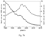
- Figure 7a and Figure 7b show China's traffic accident statistics from 1990 to 2015.
- Figure 7a shows the number of domestic traffic accidents from 1990 to 2015.
- Figure 7b shows the number of deaths and death rates from 1990 to 2015. It can be seen from the figure that the number of road traffic accidents and fatalities reached the maximum in 2002, and the number of road traffic accidents and deaths decreased sharply until 2008, showing a steady and declining trend. However, the total amount is still high, becoming a major accident threatening national safety. Classify statistics on the factors that cause traffic accidents. Traffic accidents caused by driver errors accounted for 85%-92% of the total number of accidents. Traffic accidents caused by driver factors accounted for 88.23% of total accidents. Traffic accident casualties accounted for 90.6% of the total casualties.
- the road traffic system is a complex dynamic system composed of people, vehicles and roads.
- the driver continuously obtains information from the road environment. This information is integrated into the driver's brain, through a complex decision-making process to make judgments and form action instructions. Through the driver's execution of instructions, the car produces corresponding actions on the road. During operation, changes in the running state of the car and the road environment are fed back to the driver as new information, and the cycle repeats to complete the driving task.
- the three elements of people, vehicles and roads are indispensable in the traffic system.
Landscapes
- Engineering & Computer Science (AREA)
- Business, Economics & Management (AREA)
- Human Resources & Organizations (AREA)
- Physics & Mathematics (AREA)
- General Physics & Mathematics (AREA)
- Analytical Chemistry (AREA)
- Strategic Management (AREA)
- Chemical & Material Sciences (AREA)
- Entrepreneurship & Innovation (AREA)
- Economics (AREA)
- Human Computer Interaction (AREA)
- Quality & Reliability (AREA)
- Mechanical Engineering (AREA)
- Educational Administration (AREA)
- Transportation (AREA)
- Game Theory and Decision Science (AREA)
- Automation & Control Theory (AREA)
- Marketing (AREA)
- Operations Research (AREA)
- Development Economics (AREA)
- Tourism & Hospitality (AREA)
- General Business, Economics & Management (AREA)
- Theoretical Computer Science (AREA)
- Life Sciences & Earth Sciences (AREA)
- Atmospheric Sciences (AREA)
- Traffic Control Systems (AREA)
- Control Of Driving Devices And Active Controlling Of Vehicle (AREA)
Abstract
Description
- The invention relates to traffic safety, in particular to a vehicle intelligent safety decision-making method based on a driving safety field.
- In recent years, China's economy has developed rapidly, the process of automobileization has also been advancing rapidly, and the number of cars has increased rapidly. At the same time, China's road traffic safety has become increasingly severe. Traditional vehicle decision-making methods during driving are mostly based on the driver's intention recognition, coupled with the relevant constraints of vehicle dynamics or road planning, the factors considered in the decision-making process are insufficient and cannot make correct driving decisions. In the decision-making process, the existing safety decision-making methods and theories usually do not fully consider the role of the driver-vehicle-road system in traffic behavior, especially the lack of attention and research on the psychological characteristics of people (drivers). In addition, the research method is basically at a single correlation level, that is, taking a certain influencing factor as an independent variable, taking the change of vehicle performance index as the target value to reflect vehicle safety, and conventionally directly linking the two factors, so as to analyze the impact of this factor on vehicle safety. The purpose of vehicle decision-making is to ensure driving safety, thereby promoting the safety of the entire transportation system. The safety of the traffic system depends on the coordination between the reliability of the objective safety guarantee and the driver's perception of the performance of such reliable information. That is, the traffic safety is related to the objective safety guarantee and the driver's sense of safety. When the two are coordinated and unified, system traffic safety can be realized. Research on vehicle intelligent safety decision-making methods can effectively promote major changes in the automotive industry. Vehicle safety is the most important goal of intelligence. The quantitative assessment of driving risks and intelligent safety decision-making are the realization of vehicle intelligence such as driving assistance, unmanned driving, and vehicle-road collaboration. However, my country's complex mixed traffic environment urgently needs new automotive intelligent safety theory and methods to break through the development bottleneck in vehicle intelligence.
- At present, there have been preliminary results in driving safety control methods for single goals such as vehicle safety control and road safety assessment at home and abroad, but the multi-objective, unified and coordinated driving safety control method that comprehensively considers people, vehicles and roads is still developing.
- When analyzing the driver's intelligent and safe decision-making during the driving process, the present invention links the field theory knowledge with the role that the driver receives during the driving process by analyzing the indicators pursued during the driving process. Initially applying the concept of field theory in psychology, Lewin proposed the principle of psychology, which is defined as a psychological field. The field generated by the process of using experienced drivers to quickly identify obstacles, combined with relative speed, road conditions, and self-driving cars State, and then plan a reasonable feasible boundary; the potential energy field method is usually used in path planning in the robot field to realize path planning and dynamic steering control. Arkin RC uses the artificial potential energy field method to achieve indoor path planning and active collision avoidance for mobile robots ; Reichardt D of Daimler-Benz regards the driving environment as a map centered on an autonomous vehicle and treats each coordinate point as a charged particle to study the impact of risks on the movement of smart cars, but the study is simplified The actual environmental factors and ignoring the driver factor; Kitamura Y et al. used artificial potential energy field to study the path planning of automatic aircraft in a 3D environment, and believed that this method can solve the problem of multi-moving bodies; Wolf MT et al. used Tang Chuanshi proposed a highway vehicle collision avoidance algorithm, which uses the idea of electric field to establish the potential energy field generated by the self-car and other cars, and conducts collision avoidance path planning research on the self-car in typical scenarios such as following, overtaking, and congestion. But the scene is simplified to a certain extent, and this algorithm is only effective for specific scenes; Tourveloudis NC et al. installed ultrasonic sensors around the mobile car to perceive the surrounding obstacles and determine the relative importance of the obstacles; Reichardt et al. The electric field model is introduced to study the collision avoidance behavior of dynamic highway unmanned vehicles. Two positive charge models are used to simulate the repulsive state of two vehicles during driving. The electric field force calculation formula is used to calculate the nominal electric field force and applied to the longitudinal and lateral directions. Control model. The whole theory is relatively mature, but the driver's own decision-making is not well considered, and the coupling characteristics in the coordinated environment are ignored. Aiming at the problem that the current traffic safety model cannot fully reflect the risks caused by various traffic elements such as people, cars and roads to the traffic environment, Wang Jianqiang and others proposed the idea of driving risk field. Their model covers the problems of people, cars and roads. There are a large number of parameters, but this model only provides auxiliary decision-making for driving safety, and cannot provide accurate judgment basis for vehicle intelligent safety decision-making evaluation in complex traffic environment.
- After the above analysis, when considering making intelligent safety decisions for vehicles, it is necessary to comprehensively consider all influencing factors that affect decision safety. At present, existing studies are relatively scattered when considering the safety factors of vehicle decision-making, mainly for specific scenarios, similar to the driving assistance equipment configured on the car, which deals with the problem alone, but has not yet constituted a system to coordinate the problem solving assembly. However, the one-by-one analysis of a single influencing factor is one-sided to the vehicle's intelligent safety decision-making process and cannot guarantee real-time correct decisions. In actual vehicle driving, how to accurately and quantitatively evaluate the dangerous situation of vehicle driving and timely feedback decision support information is the key to achieving driving safety. Therefore, under the existing traffic control, there is an urgent need for a set of vehicles that comprehensively consider the various elements of the driving environment Intelligent safety decision-making methods can better realize real-time decision-making in the driving process of vehicles, and then guide drivers to drive safely, improve road traffic safety, reduce road traffic accident rates, and improve road traffic environment.
- The invention aims to provide a vehicle intelligent safety decision-making method based on a driving safety field that can provide important means for risk identification and a theoretical method of decision information support for the intelligent management and control of the traffic system.
- Therefore, the present invention provides a vehicle intelligent safety decision-making method based on a driving safety field, comprising the following steps:
-
step 1. pre-providing a driving safety field model and a driving risk identification model and a driving safety field model, in an electronic control unit of a vehicle or in a central computer system of a intelligent traffic management system; wherein, the driving safety field model is used to reflect change in traffic risk over time and space, and is established by analyzing the effect of factors of a driver-vehicle-road system on a traffic system; - step 2: using the driving safety field model to acquire a current optimal driving speed of the vehicle and safe distances between the vehicle and objects outside the vehicle when the traffic system is in a steady state; and
- step 3: acquiring, according to the current optimal driving speed and the distances obtained in
step 2, a minimum value action amount of the driving risk identification model, - Preferably, the method for acquiring the "driving risk identification model" in
step 1 comprises the following steps: - step 11. establishing a physical model describing the mechanism of driving risk, to obtain conditions of the steady state and unstable state of the traffic system;
-
step 12. based on the physical model, establishing a vehicle driving action amount model as following:
- wherein, SRisk represents a action amount of the vehicle in a preset traffic process or action amount of all road users, in preset road section managed by the intelligent traffic management system, in the preset traffic process,
- t1 is start time of the preset traffic process, t2 is end time of the preset traffic process;
- step 13: acquiring, according to the vehicle driving action amount model, the driving risk identification model corresponding to driving scene of the traffic system.
- Preferably, the "driving safety field model" in
step 1 is defined as:


- Preferably,
step 2 includes: defining


- wherein, U̇ji reflects change rate of potential energy over time and space,
- k, k1, k2 each is an undetermined parameter, k1 is specifically expressed as the variation coefficient of the field, and k2 is specifically expressed as the variation coefficient of the potential energy over time and space;
- defining the "current optimal driving speed " in
step 2 as v*, then force acted on the vehicle i running in the traffic system is f(v*); - when the vehicle reaches a steady state and the traffic system is in a steady state, U̇ji = f(v*), namely:
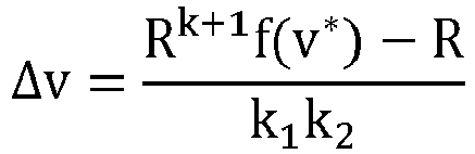
- the traffic system reaches equilibrium when the vehicle speed is constant, at this time, Δv=0,


- in the formula, R represents the safe driving distance between the vehicle and objects outside the vehicle.
- Preferably, the "physical model" in step 11 is used for describing the mechanism of driving risk, and method for establishing the physical model is as follows:
- in an U-shaped groove, a ball moves along the path of the groove, when the resistance and gravitational force are in balance, the ball is in a steady state; when an obstacle is encountered, the ball will deviate from the safety limit, and the ball is in an unstable state at this time;
- the U-shaped groove corresponds to the traffic system, the ball corresponds to the vehicle, and the change in the angle between the U-shaped groove and horizontal reference corresponds to the different needs of the driver for speed, and the conditions of the steady state and the unstable state of the traffic system are expressed as:
- When

- when


- When
- Preferably, in a free driving scene of a single vehicle, the action amount of the driving risk identification model SRisk is expressed as following,

thestep 3 specifically includes: - Step 31: acquiring minimum value

- Step 32: in a free driving scene of a single vehicle, when the traffic system reaches a steady state, the vehicle is moving at a constant speed, and the risk is minimal, at this time,


- Preferably, in a vehicle following scene, the action amount of the driving risk identification model SRisk is expressed as following,

thestep 3 specifically includes: - step 31: acquiring minimum value

- step 32. in a vehicle following scene, Δv = vego - v1, is always positive, calculating the current driving risk level value LRisk of the vehicle through the following formula:

- The present invention has the following advantages.
- 1. The present invention clarifies the interaction between traffic safety influencing factors based on field theory for the first time, reveals the driver-vehicle-road interaction mechanism, and establishes a unified vehicle safety assessment model for comprehensive traffic factors. The risk assessment model of a single influencing factor has its limitations, and the real driving task is in an extremely complex system composed of a person, a vehicle, and the environment inside and outside the vehicle. Therefore, only by considering the coupling relationship between various factors to construct a unified driving safety assessment model can we better make decision support for the intelligent control of traffic environment safety.
- 2. The present invention changes the focus of previous risk research, distinguishes different types of decision makers and traffic environment object attributes, measures their contribution to the traffic environment, and reveals the objective existence of risks and the mechanism of driving instability. The present invention analyzes the factors that affect the risk effect, and makes a specific risk interpretation of the entire road traffic system from the perspective of field theory, thereby revealing the driver-vehicle-road interaction mechanism and the law of influence of various traffic elements on driving safety. The present invention further studies the relationship between driver manipulation and risk effects, and develops risk assessment algorithms adapted to complex environments.
- 3. The present invention is based on the principle of minimum action, and reveals the mechanism of driving risk, that is, the fundamental cause of driving risk. The motivation is that the driver's control deviates from the minimum of the product of risk and time. The invention seeks an equilibrium value of high speed and low risk, and provides a decision-making basis for driving safety intelligent control.
-
-
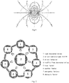
Figure 1 is a schematic diagram of the principle of the present invention borrowing from the physical field; -
Figure 2 is a schematic diagram of analysis of risk factors in the transportation system of the present invention; -
Figure 3 is a schematic diagram of the corresponding relationship between various risks of driving and various fields of the present invention; -
Figure 4a is a schematic diagram of the physical model of the present invention in its initial state; -
Figure 4b is a schematic diagram of the physical model of the present invention when it is in a steady state; -
Figure 4c is a schematic diagram of the physical model of the present invention when instability occurs; -
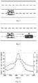
Figure 5 is a schematic diagram of a free driving scene of the present invention and a schematic diagram of field strength distribution of the corresponding driving risk field; -
Figure 6 is a schematic diagram of a car following scene and the corresponding field strength distribution of the driving risk field of the present invention; -
Figure 7a shows the number of domestic traffic accidents and deaths from 1990 to 2015; -
Figure 7b shows the traffic accident mortality rate from 1990 to 2015. - The present invention will be described in detail below with reference to the drawings and embodiments.
- Therefore, the present invention provides a vehicle intelligent safety decision-making method based on a driving safety field, comprising the following steps:
step 1. pre-providing a driving safety field model and a driving risk identification model and a driving safety field model, in an electronic control unit of a vehicle or in a central computer system of a intelligent traffic management system. The driving safety field model is used to reflect change in traffic risk over time and space, and is established by analyzing the effect of factors of a driver-vehicle-road system on a traffic system. - As shown in
Fig. 1 , The driving safety field defined in the present invention is a basic model based on the physical field, and the driving risk is described on the base of the basic model. The existence of object obstacles leads to the formation of the potential energy field formed by stationary objects on the road, the kinetic energy field formed by moving objects, and the behavior field formed by the drivers. These objects each produces a field range centered on themselves and interfere with other objects. The invention applies the field theory idea in the traffic system. The objective existence of various traffic element risks in the driving safety field corresponds to the objective existence and universality of the physical field. The field in the driving safety field can be characterized as a space-time function, and the physical field also changes with time and space, which is measurable. The risk impact in the driving safety field has a field-like direction. - From
Figures 2 and3 , it can be concluded that by analyzing the vehicle safety field model and the factors that affect the safety of the traffic system, methods and measures to reduce the probability and severity of accidents are proposed. Associate the safety level of transportation facilities with various risk factors in the driver-vehicle-road-environment system, thereby predicting the safety level under different values and combinations of factors, so as to obtain efficient improvement measures to improve the safety level. - Step 2: using the driving safety field model to acquire a current optimal driving speed of the vehicle and safe distances between the vehicle and objects outside the vehicle when the traffic system is in a steady state.
- Step 3: acquiring, according to the current optimal driving speed and the distances obtained in
step 2, a minimum value action amount of the driving risk identification model, and using a risk normalized evaluation index to comprehensively describe and quantitatively evaluate dangerous driving situation of the vehicle, and then acquiring a current driving risk level value of the vehicle. - In this embodiment, by analyzing the coupling relationship of various factors of the driver-vehicle-road system and their contribution to the safety of the traffic system, a driving safety field model with dynamic changes in risk is constructed to provide a basis for driving safety decision-making. Based on the principle of least action, the risk normalized evaluation index is used to comprehensively describe and quantitatively evaluate the dangerous driving situation of road vehicles. This embodiment also conducts risk analysis on the current driving of the vehicle to obtain the current driving risk level value of the vehicle. This embodiment realizes the intelligent control of driving operation, and finally achieves the goal of safety regulation of the road traffic system so as to reduce the incidence of road collision traffic accidents.
- In an embodiment, the method for acquiring the "driving risk identification model" in
step 1 comprises the following steps: - step 11. establishing a physical model describing the mechanism of driving risk, to obtain conditions of the steady state and unstable state of the traffic system. In this step, a "physical model" is used to clarify the mechanism of driving risk in detail, and a physical model is built to visually show the critical threshold when the traffic system is in a steady state and an unstable state.
-
Step 12. based on the physical model, establishing a vehicle driving action amount model as following:
- The "physical model" explains the causes of driving risks. According to the idea of the principle of least action, when the transportation process is realized, there are many ways to choose. Nature always chooses the way that minimizes the product of time and energy. The driving behavior of drivers also pursues speed and safety at the same time, which conforms to the principle of least action. At the same time, it reveals the mechanism of driving risk based on the principle of minimum action. The driver's deviation from the minimum action is the fundamental cause of driving risk. The degree of action deviation from the extreme value determines the magnitude of the driving risk. Based on this idea, the vehicle driving action amount model is established.
- Step 13: acquiring, according to the vehicle driving action amount model, the driving risk identification model corresponding to driving scene of the traffic system.
- The "driving scene" may be, for example, a "single vehicle free driving scene" or a "vehicle following scene".
- In one embodiment, as shown in
Figures 2 and3 , to ensure driving safety and intelligently control the traffic system, it is necessary to analyze various factors that affect the traffic system to obtain the interrelationship between the factors. In a complete transportation system, the driving process is mainly related to the characteristics of the driver, the physical characteristics of the vehicle, and the characteristics of the road traffic environment. These characteristics interfere with the entire driving process and lay the foundation for the influencing factors that need to be considered in the subsequent model construction. The main influencing factors can be summarized into the following categories: - a) Driver factor (driver and driving target vehicle), the driver manipulates in the vehicle or interacts with driving assistance devices or semi-autonomous vehicles. Its impact on the traffic system is mainly reflected in the driver's manipulation strategy and Behavior results (target path, keeping lane, following distance, driving speed). Drivers' characteristics are mainly reflected in the various links of the perception-decision-operation mechanism during the driving process. Differences in physiological functions, psychological conditions, habits, etc. of drivers, as well as differences in cognition, processing and driving techniques of traffic information will lead to driving decisions The differences in vehicle control methods are externalized as differences in driving behavior.
- b) Factors of road users (motor vehicles, non-motor vehicles, pedestrians, etc.),
The factor of road users is the impact of moving objects in the traffic environment on the entire traffic system. By analyzing the influence of other road users' motion status on the target vehicle, the evolution law of the direction of intelligent safety control can be analyzed; - c) Road environmental factors (road and objective environment)
- Road conditions include road adhesion coefficient, road alignment, lane function and location, road facilities, location of traffic signs and markings, etc. The environmental conditions mainly include surrounding environmental conditions, weather conditions, traffic system conditions, etc. Through analysis of them, the contribution of road environmental factors to the traffic environment risk value is highlighted.
- This embodiment takes the driving safety field formed by vehicle i as an example for description.
- Definition: When a vehicle is driving in a traffic environment, there is a resistance field caused by rolling resistance, climbing assistance, acceleration resistance, and air resistance. The expression of the resistance field can be expressed as:


- For any object that exists in the traffic environment, such as vehicles, pedestrians, non-motor vehicles, etc., the magnitude of the risk to the entire traffic system is related to its quality, type, and its motion state, especially speed. Therefore, the concept of "equivalent quality" is used for reference, namely:


- Mi represents the equivalent mass of the risk of the object to the driving system in the traffic environment. The greater the mass, the greater the loss that can be caused when the vehicle i collides with the vehicle.
- mi is the actual physical mass of vehicle i, Ti is the type of vehicle i, and vi is the speed of vehicle i. According to the idea of driving safety field, the field strength generated by moving objects is as follows:


- Definition: The vehicle has a certain potential energy in the space position under the action of the field force in the driving safety field, which is the safety potential energy. Uji is used to represent the distribution of driving risk in time and space.
- When vehicle j is at rji from vehicle i, or when vehicle i is at (xi, yi), the potential energy Uji of vehicle I, due to action of vehicle j, is:

- That is, the expression of the "vehicle safety field model" in
step 1 is:
- K > 0 and K is an undetermined constant,and It can be calibrated by using artificial potential energy field.
- DRi represents the driver's effect factor; Ri represents resistance field of vehicle i caused by rolling resistance, climbing resistance, acceleration resistance, and air resistance; Rj represents the resistance field of vehicle j caused by rolling resistance, climbing resistance, acceleration resistance, and air resistance to vehicle j. Mi represents equivalent mass of vehicle i; Mj represents equivalent mass of vehicle j; mi is the mass of vehicle i; xi is the longitudinal displacement of vehicle i; ẋ1 is the longitudinal velocity of vehicle i; ẍi is the longitudinal acceleration of vehicle i; g is acceleration of gravity; f is the rolling resistance coefficient; iα is gradient; CDi is drag coefficient of vehicle i; CDj is drag coefficient of vehicle j; Ai is the windward area of vehicle i; Aj is the windward area of vehicle j; λi is conversion coefficient for rotation mass of vehicle i; λj is conversion factor for rotation mass of vehicle j; Ti is type of vehicle i; Tj is type of vehicle j; vi is speed of vehicle i; vj is speed of vehicle j.
- It should be noted that: vehicle j is a road user or obstacle other than vehicle i; vehicle i is the current research target vehicle.
-
Step 2 includes:
defining
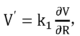

- wherein, U̇ji reflects change rate of potential energy over time and space,
- k, k1, k2 each is an undetermined parameter, k1 is specifically expressed as the variation coefficient of the field, and k2 is specifically expressed as the variation coefficient of the potential energy over time and space.
- defining the "current optimal driving speed " in
step 2 as v*, then force acted on the vehicle i running in the traffic system is f(v*); - when the vehicle reaches a steady state and the traffic system is in a steady state, U̇ji = f(v*), namely:

- the traffic system reaches equilibrium when the vehicle speed is constant, at this time, Δv=0,


- in the formula, R represents the safe driving distance between the vehicle and objects outside the vehicle.
- The mechanism provided in this embodiment lays a theoretical foundation for accurate assessment of driving risks.
- In one embodiment, as shown in
FIG. 4 , the "physical model" instep 2 is used to perform driving maneuvers in a traffic environment, and to explain the mechanism of driving risk. The method for establishing the physical model as follows:
in an U-shaped groove, a ball moves along the path of the groove as shown inFig. 4a , when the resistance and gravitational force are in balance, the ball is in a steady state, as shown inFig. 4b . When an obstacle is encountered, the ball will deviate from the safety limit, and the ball is in an unstable state at this time, as shown inFig. 4c . - That is to say, in the traffic system, the driver's manipulation process is analogous to a small ball rolling in a U-shaped groove. If the driver's expectation of high efficiency is too large, that is, θ_i is too large, the small ball will cross the safety limit, and the resultant force will There will be unbalanced forces, and the ball is in an unstable state.
- The U-shaped groove corresponds to the traffic system, the ball corresponds to the vehicle, and the change in the angle between the U-shaped groove and horizontal reference corresponds to the different needs of the driver for speed, and the conditions of the steady state and the unstable state of the traffic system are expressed as:
- When

- when θi


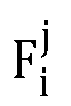
- Gi, Ri, etc. all represent the force that the ball i receives during the movement, and other labeled balls such as j can also be added, similar to the traffic system with many cars.
-
Fig. 5 shows the traffic risk assessment and safety control in a free driving vehicle scene. For a free driving vehicle, when it is in an steady state, according to the characteristics of the traffic system, along the forward direction of the vehicle, in the free driving state, when the traffic system reaches a steady state, the self-vehicle moves at a constant speed, which reaches the optimal state When the risk is minimal, there are:
- The Lagrangian equation is established for the traffic system in the free driving state, and no other vehicles affect it in this state. According to the directional flow phenomenon of the traffic system, it is assumed that there is a gravity-like gravitational field Gi along the direction of traffic flow.
- The system Lagrangian equation for free driving is:

- Among them, T represents the total kinetic energy of the system, and U represents the total potential energy of the system.
- Considering the influence of lane lines or road boundaries, according to the theory of traffic safety field, the vector field strength Eij at (xi, y;) of the potential energy field formed by lane line a at (xa, ya) can be expressed as:

- Among them, LTa represents the type of lane line a, and its amount is determined by local traffic regulations (for example, the white solid line corresponds to a larger value than the white dashed line), D is the lane width, rai = (xi - xa, yi - ya) is the distance vector from the lane line a to the center of mass (xi, yi) of the vehicle represented by the white rectangular box in
Figure 2 , and the range of |r ai| is [0,D/2], The closer the vehicle is to such stationary objects, the greater the restraint potential energy of the vehicle. Then, the field force generated by the lane line can be described as:
- Therefore, the Lagrangian equation of a single free driving vehicle traffic system considering lane lines can be expressed as:



- Similarly, if the traffic signs are taken into consideration, let Fsign be the resistance of the traffic signs to driving behavior. The resistance is related to the driver's degree of compliance with traffic rules. According to the driving safety field theory:

- The forces generated by traffic signs, etc. are integrated into the changes in safety potential energy.
- The invention is based on the principle of the least action amount, and uses the risk normalization evaluation index to comprehensively describe and quantitatively evaluate the dangerous driving situation of road vehicles. Moreover, the present invention conducts example analysis on free driving and car following scenes, thereby realizing intelligent control of driving operation, and finally achieving the goal of road traffic system safety regulation and reducing the incidence of road collision accidents.
- If traffic risk is regarded as an action quantity, when the optimal state is reached through traffic control, there is bound to be a process that minimizes traffic risk under the premise of high efficiency. According to the Lagrangian equation of the system:

- In the driving safety field theory, the action amount = driving risk × driving time = Risk *


- The degree of traffic risk is LRisk, and is defined as:

- SRisk,t represents the amount of action of the traffic system in the real world . When

- Based on the above theory, in a free driving scene of a single vehicle, the expression of the "action amount SRisk of the driving risk identification model" is:

- The
step 3 specifically includes: - Step 31: acquiring minimum value


- Step 32: in a free driving scene of a single vehicle, when the traffic system reaches a steady state, the vehicle is moving at a constant speed, and the risk is minimal, at this time,


- The driving behavior is adjusted according to the driving risk level value LRisk, so as to pursue the optimal driving state.
- As shown in
Fig.6 , in the vehicle-following scene, Δv = vego- v1 is always positive.
- It can be seen from the above formula that when Δv increases in a two-vehicles following scene, in order to keep the potential energy change trend between the two vehicles consistent, R also needs to be increased, and in the vehicles scene, v* = vmin
- The Lagrangian equation of the system at this time is:

- U12 is potential energy of the second vehicle under the potential energy field generated by the first vehicle; U21 is the potential energy of the first vehicle under the potential energy field generated by the second vehicle.
- If there are n vehicles and b lane boundaries in the traffic environment, L can be described as:

- At this time, the action amount of the traffic system in the vehicle following scene is:


- Therefore, in a vehicle following scene, the action amount of the driving risk identification model SRisk is expressed as following,

-
Step 3 specifically includes: - step 31: acquiring minimum value

- step 32. in a vehicle following scene, Δv = vego- v1, is always positive, calculating the current driving risk level value LRisk of the vehicle through the following formula:

- The driving scenes in the present invention specifically includes the following.
- For a single-vehicle free-driving scene, the effect amount is expressed as:

- It should be noted that in the above parameters, vehicle i is the vehicle platform itself, so mi is known here; ẋi, ẋi, xi, steering angle information, and GPS location are all CAN data of the vehicle, and other sensors may collect relative speed, relative displacement between vehicles, position information of other vehicles, etc. The acquisition of these data mainly depends on the vehicle CAN bus, millimeter wave radar, camera, lidar, vision sensor, etc.
- f, i_α, C _Di, A_i, and λ_i can be obtained from the contents of technical manuals or textbooks. k_i is the gravitational coefficient of gravity. Its change has little effect on the trend of the results. It can be calibrated by experimental data. Usually k_i∈[1,10]. k, k1, and k2 are undetermined coefficients, and can be calibrated by artificial potential energy field method.
- In the above embodiments, the reference coordinate system can be defined as: the x-axis is a horizontal axis parallel to the traveling direction of the own vehicle, the y-axis is a vertical axis perpendicular to the traveling direction of the own vehicle, and the positive direction of the x-axis is the traveling direction of the own vehicle. The coordinates of the own vehicle are (0, 0).
-
Figure 7a andFigure 7b show China's traffic accident statistics from 1990 to 2015.Figure 7a shows the number of domestic traffic accidents from 1990 to 2015.Figure 7b shows the number of deaths and death rates from 1990 to 2015. It can be seen from the figure that the number of road traffic accidents and fatalities reached the maximum in 2002, and the number of road traffic accidents and deaths decreased sharply until 2008, showing a steady and declining trend. However, the total amount is still high, becoming a major accident threatening national safety. Classify statistics on the factors that cause traffic accidents. Traffic accidents caused by driver errors accounted for 85%-92% of the total number of accidents. Traffic accidents caused by driver factors accounted for 88.23% of total accidents. Traffic accident casualties accounted for 90.6% of the total casualties. Traffic accidents caused by road environmental factors accounted for 8%-11.2%. Therefore, in a road traffic system composed of people, cars, and roads, the car is the core component, the driving behavior of the driver is the core behavior, and the road and the environment are the basic conditions for car driving. Intelligent management and control of the system is an important means to improve traffic efficiency and road traffic system safety. - The road traffic system is a complex dynamic system composed of people, vehicles and roads. In this system, the driver continuously obtains information from the road environment. This information is integrated into the driver's brain, through a complex decision-making process to make judgments and form action instructions. Through the driver's execution of instructions, the car produces corresponding actions on the road. During operation, changes in the running state of the car and the road environment are fed back to the driver as new information, and the cycle repeats to complete the driving task. When there is a problem in the coordination of the transportation system composed of the three elements of people, vehicles and roads, it may cause traffic accidents. The three elements of people, vehicles and roads are indispensable in the traffic system.
- The above-mentioned embodiments are only used to illustrate the present invention, in which the various steps of the method can be changed, and all equivalent changes and improvements made on the basis of the technical solution of the present invention fall within the protection scope of the present invention.
Claims (7)
- A vehicle intelligent safety decision-making method based on a driving safety field, comprising the following steps:step 1. pre-providing a driving safety field model and a driving risk identification model and a driving safety field model, in an electronic control unit of a vehicle or in a central computer system of a intelligent traffic management system; wherein, the driving safety field model is used to reflect change in traffic risk over time and space, and is established by analyzing the effect of factors of a driver-vehicle-road system on a traffic system;step 2: using the driving safety field model to acquire a current optimal driving speed of the vehicle and safe distances between the vehicle and objects outside the vehicle when the traffic system is in a steady state; andstep 3: acquiring, according to the current optimal driving speed and the distances obtained in step 2, a minimum value action amount of the driving risk identification model,using a risk normalized evaluation index to comprehensively describe and quantitatively 27 evaluate dangerous driving situation of the vehicle, and then acquiring a current driving risk level value of the vehicle.
- The vehicle intelligent safety decision-making method based on the driving safety field according to claim 1, wherein the method for acquiring the "driving risk identification model" in step 1 comprises the following steps:step 11. establishing a physical model describing the mechanism of driving risk, to obtain conditions of the steady state and unstable state of the traffic system;step 12. based on the physical model, establishing a vehicle driving action amount model as following:
 wherein, SRisk represents a action amount of the vehicle in a preset traffic process or action amount of all road users, in preset road section managed by the intelligent traffic management system, in the preset traffic process,t1 is start time of the preset traffic process, t2 is end time of the preset traffic process;step 13: acquiring, according to the vehicle driving action amount model, the driving risk identification model corresponding to driving scene of the traffic system.
 - The vehicle intelligent safety decision-making method based on the driving safety field of claim 2, wherein the "driving safety field model" is defined as:



- The vehicle intelligent safety decision-making method based on the driving safety field of claim 3, characterized in that, step 2 includes:defining


 wherein, U̇ji reflects change rate of potential energy over time and space,k, k1, k2 each is an undetermined parameter, k1 is specifically expressed as the variation coefficient of the field, and k2 is specifically expressed as the variation coefficient of the potential energy over time and space;defining the "current optimal driving speed " in step 2 as v*, then force acted on the vehicle i running in the traffic system is f(v*);when the vehicle reaches a steady state and the traffic system is in a steady state, U̇ji = f(v*), namely:
 the traffic system reaches equilibrium when the vehicle speed is constant, at this time, Δv=0,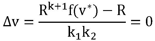
 in the formula, R represents the safe driving distance between the vehicle and objects outside the vehicle.
 - The vehicle intelligent safety decision-making method based on the driving safety field as claimed in claim 4, characterized in that the "physical model" in step 11 is used for describing the mechanism of driving risk, and method for establishing the physical model is as follows:in an U-shaped groove, a ball moves along the path of the groove, when the resistance and gravitational force are in balance, the ball is in a steady state; when an obstacle is encountered, the ball will deviate from the safety limit, and the ball is in an unstable state at this time;the U-shaped groove corresponds to the traffic system, the ball corresponds to the vehicle, and the change in the angle between the U-shaped groove and horizontal reference corresponds to the different needs of the driver for speed, and the conditions of the steady state and the unstable state of the traffic system are expressed as:When
 when
when


- The vehicle intelligent safety decision-making method based on the driving safety field of any one of claims 1 to 5, characterized in that, in a free driving scene of a single vehicle, the action amount of the driving risk identification model SRisk is expressed as following,

wherein, mi is the mass of vehicle i; ki is the gravitational coefficient of the vehicle i; xi is the longitudinal displacement of vehicle i; ẋ1 is the longitudinal velocity of vehicle i; ẍi is the longitudinal acceleration of the vehicle; g is gravitational acceleration; f is the rolling resistance coefficient; iα is the gradient; CDi is the wind resistance coefficient of the vehicle; Ai is the windward area of the vehicle; λi is the rotational quality coefficient of the vehicle; to is an initial time; tf is the end time; x0 is the departure point; xf is the destination,
the step 3 specifically includes:Step 31: acquiring minimum value Step 32: in a free driving scene of a single vehicle, when the traffic system reaches a steady state, the vehicle is moving at a constant speed, and the risk is minimal, at this time,

- The vehicle intelligent safety decision-making method based on the driving safety field of any one of claims 1 to 5, characterized in that, in a vehicle following scene, the action amount of the driving risk identification model SRisk is expressed as following,

the step 3 specifically includes:step 31: acquiring minimum value SRisk of action amount SRisk; andstep 32. in a vehicle following scene, Δv = vego- v1, is always positive, calculating the current driving risk level value LRisk of the vehicle through the following formula:
Applications Claiming Priority (2)
| Application Number | Priority Date | Filing Date | Title |
|---|---|---|---|
| CN201810433464.XA CN108648447B (en) | 2018-05-08 | 2018-05-08 | Vehicle intelligent safety decision-making method based on driving safety field |
| PCT/CN2018/086638 WO2019213980A1 (en) | 2018-05-08 | 2018-05-14 | Intelligent vehicle safety decision-making method employing driving safety field |
Publications (2)
| Publication Number | Publication Date |
|---|---|
| EP3792893A1 true EP3792893A1 (en) | 2021-03-17 |
| EP3792893A4 EP3792893A4 (en) | 2021-06-30 |
Family
ID=63749408
Family Applications (1)
| Application Number | Title | Priority Date | Filing Date |
|---|---|---|---|
| EP18917585.4A Withdrawn EP3792893A4 (en) | 2018-05-08 | 2018-05-14 | INTELLIGENT VEHICLE SAFETY DECISION-MAKING PROCESS USING A DRIVING SAFETY FIELD |
Country Status (3)
| Country | Link |
|---|---|
| EP (1) | EP3792893A4 (en) |
| CN (1) | CN108648447B (en) |
| WO (1) | WO2019213980A1 (en) |
Cited By (4)
| Publication number | Priority date | Publication date | Assignee | Title |
|---|---|---|---|---|
| CN113487874A (en) * | 2021-05-27 | 2021-10-08 | 中汽研(天津)汽车工程研究院有限公司 | System and method for collecting, identifying and classifying following behavior scene data |
| CN114162133A (en) * | 2021-11-10 | 2022-03-11 | 上海人工智能创新中心 | Risk assessment method and device for driving scene and computer readable storage medium |
| CN119849934A (en) * | 2024-12-27 | 2025-04-18 | 福州大学 | Comprehensive real-time assessment system and method for risk of sports in field |
| US12630106B1 (en) | 2025-05-06 | 2026-05-19 | Ford Global Technologies, Llc | Deployable halo for open-air vehicle |
Families Citing this family (68)
| Publication number | Priority date | Publication date | Assignee | Title |
|---|---|---|---|---|
| CN109712396A (en) * | 2019-01-22 | 2019-05-03 | 深圳成有科技有限公司 | A kind of modeling method and system of bus or train route collaboration road surface wagon flow |
| CN109933945B (en) * | 2019-03-28 | 2023-10-24 | 北京智行者科技股份有限公司 | Traffic environment modeling method |
| WO2020248130A1 (en) * | 2019-06-11 | 2020-12-17 | 深圳市大疆创新科技有限公司 | Control method and device for movable platform, movable platform and storage medium |
| CN110398968B (en) * | 2019-07-24 | 2020-06-05 | 清华大学 | Intelligent vehicle multi-target driving control method and decision system |
| CN110414831B (en) * | 2019-07-24 | 2020-04-03 | 清华大学 | Risk assessment method and device for human-vehicle-road coupling based on driver's cognitive perspective |
| CN110505601A (en) * | 2019-07-30 | 2019-11-26 | 大连理工大学 | Information sending frequency optimization method based on vehicle driving situation field model in Internet of Vehicles |
| CN111079834B (en) * | 2019-12-16 | 2020-10-02 | 清华大学 | Intelligent vehicle safety situation assessment method considering multi-vehicle interaction |
| CN111401690B (en) * | 2020-02-22 | 2023-06-23 | 中国平安财产保险股份有限公司 | Fleet risk identification method, electronic device and readable storage medium |
| CN111311947B (en) * | 2020-03-02 | 2021-01-08 | 清华大学 | Driving risk assessment method and device considering driver intention in internet environment |
| CN111383481B (en) * | 2020-03-03 | 2021-07-27 | 东南大学 | Optimization method for green traffic speed of intelligent networked vehicles at urban congested intersections |
| CN113554370A (en) * | 2020-04-23 | 2021-10-26 | 中国石油化工股份有限公司 | Safety risk assessment method and device for hazardous chemical substance transport vehicle |
| CN111523822B (en) * | 2020-05-06 | 2023-07-28 | 重庆文理学院 | Driving risk unified quantification method comprehensively considering all factors of person-vehicle-road |
| CN111723470B (en) * | 2020-05-26 | 2023-05-02 | 同济大学 | Automatic driving control method based on calibration optimization RSS model |
| CN111717221B (en) * | 2020-05-29 | 2022-11-11 | 重庆大学 | Automatic driving takeover risk assessment and man-machine friendly early warning method and early warning system |
| CN112070419B (en) * | 2020-09-23 | 2023-11-07 | 交通运输部公路科学研究所 | Method for quantifying potential dangerous situational risks of car driving |
| CN112242059B (en) * | 2020-09-30 | 2021-10-01 | 南京航空航天大学 | Intelligent decision-making method for unmanned vehicles based on motivation and risk assessment |
| CN112446538B (en) * | 2020-11-23 | 2022-11-08 | 合肥工业大学 | Optimal path obtaining method based on personalized risk avoidance |
| CN112700138A (en) * | 2020-12-31 | 2021-04-23 | 京东数字科技控股股份有限公司 | Method, device and system for road traffic risk management |
| CN112644498B (en) * | 2021-01-05 | 2022-04-08 | 南京航空航天大学 | Intelligent vehicle safety decision-making method based on driving safety field |
| CN112885116B (en) * | 2021-01-25 | 2022-12-27 | 浙江公路水运工程咨询有限责任公司 | Highway rain and fog scene vehicle and road collaborative induction system |
| CN113029151B (en) * | 2021-03-15 | 2023-04-14 | 齐鲁工业大学 | An Intelligent Vehicle Path Planning Method |
| CN113112022A (en) * | 2021-04-06 | 2021-07-13 | 清华大学 | Multi-agent combined modeling method for intelligent automobile queue man-vehicle-road system |
| CN113188556B (en) * | 2021-04-27 | 2023-06-13 | 清华大学 | Method and device for trajectory planning of intelligent networked vehicles based on driving safety field |
| CN113487863A (en) * | 2021-06-30 | 2021-10-08 | 中国科学技术大学先进技术研究院 | Multi-factor traffic risk real-time quantitative evaluation system and method |
| CN113479197A (en) * | 2021-06-30 | 2021-10-08 | 银隆新能源股份有限公司 | Control method of vehicle, control device of vehicle, and computer-readable storage medium |
| CN113468670B (en) * | 2021-07-20 | 2023-11-03 | 合肥工业大学 | A vehicle-level performance evaluation method for autonomous vehicles |
| CN113506036A (en) * | 2021-07-29 | 2021-10-15 | 清华大学 | Vehicle collision risk evaluation method and device based on pedestrian psychological safety distance |
| CN113370980B (en) * | 2021-08-16 | 2021-11-02 | 清华大学 | Method and device for comprehensive risk assessment of vehicle instability and collision under extreme conditions |
| CN113781806B (en) * | 2021-09-23 | 2022-05-24 | 西南交通大学 | A method for mixed traffic flow in an intelligent networked environment |
| CN113635897B (en) * | 2021-09-24 | 2023-03-31 | 北京航空航天大学 | Safe driving early warning method based on risk field |
| CN113946943B (en) * | 2021-09-26 | 2022-06-21 | 清华大学 | Human-vehicle-road micro traffic system modeling and risk identification method and device |
| CN113788014B (en) * | 2021-10-09 | 2023-01-24 | 华东理工大学 | A method and system for avoiding special vehicles based on repulsion field model |
| CN114331019A (en) * | 2021-12-01 | 2022-04-12 | 武汉长江通信智联技术有限公司 | Urban traffic safety risk real-time assessment method and device based on risk factor |
| CN114169444B (en) * | 2021-12-09 | 2024-03-05 | 合肥工业大学 | Driving style classification method considering risk potential field distribution under vehicle following working condition |
| CN114372708B (en) * | 2022-01-11 | 2024-09-24 | 北京航空航天大学 | A method for constructing a driving safety field model for unmanned vehicles |
| CN114407925B (en) * | 2022-01-20 | 2024-05-14 | 江苏大学 | Automatic driving track planning system and method based on space-time aerial view and strategy gradient algorithm |
| CN114613130B (en) * | 2022-02-18 | 2023-05-12 | 北京理工大学 | Driving credibility analysis method in traffic and carrying system |
| CN114863678B (en) * | 2022-04-26 | 2023-04-07 | 交通运输部公路科学研究所 | Method and system for optimal layout of road safety risk detectors in intelligent network environment |
| CN114783186B (en) * | 2022-04-26 | 2022-11-22 | 交通运输部公路科学研究所 | Optimal layout method and system for road risk early warning controller in intelligent networking environment |
| CN114912808B (en) * | 2022-05-20 | 2025-03-21 | 重庆长安汽车股份有限公司 | A method for assessing the danger level of the surrounding environment of an autonomous driving vehicle |
| CN115081822B (en) * | 2022-05-30 | 2023-09-26 | 同济大学 | A driving risk assessment method and system based on psychological and physical risk fields |
| CN115081300B (en) * | 2022-06-01 | 2024-11-08 | 东南大学 | Method for evaluating the visibility safety of intelligent driving vehicles in severe weather based on virtual simulation |
| CN115271315B (en) * | 2022-06-01 | 2026-04-28 | 东南大学 | Methods, devices, and storage media for quantifying the magnitude of driving risk fields in intelligent vehicles |
| CN114889625B (en) * | 2022-06-02 | 2024-12-24 | 东南大学 | A method for establishing a vehicle following model on a curved road based on safety potential field theory |
| CN115257738B (en) * | 2022-08-15 | 2024-10-29 | 合肥工业大学 | Intelligent vehicle following model considering cutting-in risk of adjacent vehicle |
| CN115420274B (en) * | 2022-08-16 | 2025-03-18 | 东南大学 | A road risk map generation method and system based on safety potential field |
| CN115480507B (en) * | 2022-09-02 | 2025-01-03 | 东南大学 | Intelligent vehicle safety potential field following model building method based on road longitudinal section |
| CN115320583B (en) * | 2022-10-09 | 2023-03-24 | 小米汽车科技有限公司 | Target obstacle vehicle determination method, device, vehicle and medium |
| CN115718891B (en) * | 2022-11-21 | 2025-08-26 | 同济大学 | A driver skill classification method and driving assistance system |
| CN116050162A (en) * | 2023-02-10 | 2023-05-02 | 武汉理工大学 | Decision-making method for expressway reconstruction and expansion timing based on safety and efficiency state change points |
| CN116386008B (en) * | 2023-04-06 | 2025-11-21 | 吉林大学 | Space-time coupling intelligent automobile risk assessment system considering motion uncertainty |
| CN116448136B (en) * | 2023-04-24 | 2025-07-22 | 北京航空航天大学 | Unmanned vehicle path planning method based on improved driving safety field |
| CN116384255B (en) * | 2023-05-11 | 2023-08-11 | 四川新迎顺信息技术股份有限公司 | Park dangerous situation perception method and system based on multi-source data fusion |
| CN116588123A (en) * | 2023-05-18 | 2023-08-15 | 东南大学 | Risk Perception Early Warning Strategy Method Based on Safety Potential Field Model |
| CN116363905B (en) * | 2023-05-19 | 2023-09-05 | 吉林大学 | Heterogeneous traffic flow converging region lane change time judging and active safety control method |
| CN117011827A (en) * | 2023-07-11 | 2023-11-07 | 禾多科技(北京)有限公司 | Obstacle longitudinal distance detection method, device, equipment and computer-readable medium |
| CN117111574B (en) * | 2023-08-03 | 2024-08-09 | 南京航空航天大学 | A method for safety test analysis of expected functions of intelligent drive-by-wire chassis |
| CN116699644B (en) * | 2023-08-07 | 2023-10-27 | 四川华腾公路试验检测有限责任公司 | Marking reliability assessment method based on three-dimensional laser radar |
| CN117238172A (en) * | 2023-11-13 | 2023-12-15 | 青岛理工大学 | Driving risk quantification method based on safety margin |
| CN117576949B (en) * | 2023-12-07 | 2024-10-15 | 中国民航大学 | A collision warning method for special vehicles at airports based on safety field |
| CN117644880B (en) * | 2024-01-26 | 2024-04-05 | 北京航空航天大学 | Fusion safety protection system and control method for intelligent network-connected automobile |
| CN118072552B (en) * | 2024-02-26 | 2025-04-04 | 苏州大学 | CAV multi-vehicle cooperative collision avoidance method in mixed flow environment based on composite network |
| CN118397581B (en) * | 2024-04-07 | 2025-04-25 | 湘江实验室 | Intelligent driving method based on brain-like perception and related equipment |
| CN118260769B (en) * | 2024-04-12 | 2024-11-22 | 无锡晓枫汽车技术股份有限公司 | Information security assessment method for intelligent connected vehicles based on vehicle-mounted equipment |
| CN118709366B (en) * | 2024-06-03 | 2025-05-13 | 南京林业大学 | Method for establishing driving risk field model |
| CN118571048B (en) * | 2024-06-18 | 2025-01-17 | 新汽有限公司 | Vehicle information acquisition system |
| CN120087045B (en) * | 2025-02-12 | 2025-12-12 | 江苏大学 | Circular island background traffic flow modeling method based on attention mechanism and application thereof |
| CN120878120A (en) * | 2025-07-24 | 2025-10-31 | 杭州元杰环保科技有限公司 | Multi-terminal cooperative wage resource intelligent distribution method |
Family Cites Families (11)
| Publication number | Priority date | Publication date | Assignee | Title |
|---|---|---|---|---|
| CN103927895B (en) * | 2014-04-25 | 2015-11-11 | 清华大学 | A kind of vehicle bend based on bus or train route/car car communication passes through backup system |
| CN104239741B (en) * | 2014-09-28 | 2016-05-18 | 清华大学 | Based on the automobile driving safe householder method of driving risk field |
| DE102015015259A1 (en) * | 2015-11-26 | 2016-05-12 | Daimler Ag | Method for the route guidance of a vehicle |
| CN109416873B (en) * | 2016-06-24 | 2022-02-15 | 瑞士再保险有限公司 | Autonomous or partially autonomous motor vehicle with automated risk control system and corresponding method |
| CN106485931A (en) * | 2016-11-15 | 2017-03-08 | 河北工业大学 | A kind of intersection vehicle fast passing DAS (Driver Assistant System) and method |
| CN107103185A (en) * | 2017-03-31 | 2017-08-29 | 江苏大学 | Intelligent vehicle active collision avoidance method based on grey forecasting model |
| CN107215331A (en) * | 2017-06-06 | 2017-09-29 | 北京洋浦伟业科技发展有限公司 | The safe driving control method and device of intelligent optimization |
| CN107389076B (en) * | 2017-07-01 | 2020-08-21 | 兰州交通大学 | Energy-saving real-time dynamic path planning method suitable for intelligent networked automobile |
| CN107487257A (en) * | 2017-07-31 | 2017-12-19 | 合肥光照信息科技有限公司 | A kind of omnidirectional vehicle collision early warning system and its method |
| CN107738644B (en) * | 2017-09-30 | 2019-06-21 | 长安大学 | A vehicle collision avoidance control method |
| CN107958269B (en) * | 2017-11-28 | 2020-01-24 | 江苏大学 | A Prediction Method of Driving Risk Based on Hidden Markov Model |
-
2018
- 2018-05-08 CN CN201810433464.XA patent/CN108648447B/en active Active
- 2018-05-14 EP EP18917585.4A patent/EP3792893A4/en not_active Withdrawn
- 2018-05-14 WO PCT/CN2018/086638 patent/WO2019213980A1/en not_active Ceased
Cited By (6)
| Publication number | Priority date | Publication date | Assignee | Title |
|---|---|---|---|---|
| CN113487874A (en) * | 2021-05-27 | 2021-10-08 | 中汽研(天津)汽车工程研究院有限公司 | System and method for collecting, identifying and classifying following behavior scene data |
| CN113487874B (en) * | 2021-05-27 | 2022-07-01 | 中汽研(天津)汽车工程研究院有限公司 | A system and method for data collection, recognition, classification and extraction of car-following behavior scenarios |
| CN114162133A (en) * | 2021-11-10 | 2022-03-11 | 上海人工智能创新中心 | Risk assessment method and device for driving scene and computer readable storage medium |
| CN114162133B (en) * | 2021-11-10 | 2024-06-04 | 上海人工智能创新中心 | Risk assessment method, risk assessment device and computer-readable storage medium for driving scene |
| CN119849934A (en) * | 2024-12-27 | 2025-04-18 | 福州大学 | Comprehensive real-time assessment system and method for risk of sports in field |
| US12630106B1 (en) | 2025-05-06 | 2026-05-19 | Ford Global Technologies, Llc | Deployable halo for open-air vehicle |
Also Published As
| Publication number | Publication date |
|---|---|
| EP3792893A4 (en) | 2021-06-30 |
| CN108648447B (en) | 2019-04-05 |
| CN108648447A (en) | 2018-10-12 |
| WO2019213980A1 (en) | 2019-11-14 |
Similar Documents
| Publication | Publication Date | Title |
|---|---|---|
| CN108648447B (en) | Vehicle intelligent safety decision-making method based on driving safety field | |
| CN113386795B (en) | Intelligent decision-making and local track planning method for automatic driving vehicle and decision-making system thereof | |
| CN113160547B (en) | A kind of automatic driving method and related equipment | |
| CN110531740B (en) | Intelligent degree quantitative evaluation method for intelligent vehicle | |
| CN109684702B (en) | Driving risk identification method based on trajectory prediction | |
| CN105549597B (en) | A kind of unmanned vehicle dynamic path planning method based on environmental uncertainty | |
| Chae et al. | Virtual target-based overtaking decision, motion planning, and control of autonomous vehicles | |
| CN114440908A (en) | Method and device for planning vehicle driving path, intelligent vehicle and storage medium | |
| CN113879295A (en) | Trajectory prediction method and apparatus | |
| WO2021244207A1 (en) | Method and apparatus for training driving behavior decision-making model | |
| CN109375632A (en) | A real-time trajectory planning method for autonomous vehicles | |
| US12409849B2 (en) | Method and apparatus for passing through barrier gate crossbar by vehicle | |
| WO2021000800A1 (en) | Reasoning method for road drivable region and device | |
| CN110103956A (en) | A trajectory planning method for automatic overtaking of unmanned vehicles | |
| Wang et al. | A risk-field based motion planning method for multi-vehicle conflict scenario | |
| CN112577506B (en) | Automatic driving local path planning method and system | |
| Morales et al. | Proactive driving modeling in blind intersections based on expert driver data | |
| Aryal | Optimization of geometric road design for autonomous vehicle | |
| CN121605441A (en) | System and method for providing driver assistance alert using end-to-end artificial intelligence collision avoidance system and advanced driver assistance system | |
| Guo et al. | Humanlike behavior generation in urban environment based on learning-based potentials with a low-cost lane graph | |
| Gao et al. | Ethical alignment decision making for connected autonomous vehicle in traffic dilemmas via reinforcement learning from human feedback | |
| CN114103950A (en) | Lane changing track planning method and device | |
| CN110646007A (en) | A Vehicle Driving Method Based on Formal Representation | |
| CN117533316A (en) | Intersection passing method and device, electronic equipment and readable storage medium | |
| DE102023113448A1 (en) | Systems and methods for detecting pedestrians who intend to cross a pedestrian crossing or who intend to cross a street illegally |
Legal Events
| Date | Code | Title | Description |
|---|---|---|---|
| STAA | Information on the status of an ep patent application or granted ep patent |
Free format text: STATUS: THE INTERNATIONAL PUBLICATION HAS BEEN MADE |
|
| PUAI | Public reference made under article 153(3) epc to a published international application that has entered the european phase |
Free format text: ORIGINAL CODE: 0009012 |
|
| STAA | Information on the status of an ep patent application or granted ep patent |
Free format text: STATUS: REQUEST FOR EXAMINATION WAS MADE |
|
| 17P | Request for examination filed |
Effective date: 20201208 |
|
| AK | Designated contracting states |
Kind code of ref document: A1 Designated state(s): AL AT BE BG CH CY CZ DE DK EE ES FI FR GB GR HR HU IE IS IT LI LT LU LV MC MK MT NL NO PL PT RO RS SE SI SK SM TR |
|
| AX | Request for extension of the european patent |
Extension state: BA ME |
|
| A4 | Supplementary search report drawn up and despatched |
Effective date: 20210601 |
|
| RIC1 | Information provided on ipc code assigned before grant |
Ipc: G08G 1/01 20060101AFI20210526BHEP Ipc: G06Q 10/06 20120101ALI20210526BHEP Ipc: B60W 50/00 20060101ALI20210526BHEP Ipc: G08G 1/0967 20060101ALI20210526BHEP |
|
| DAV | Request for validation of the european patent (deleted) | ||
| DAX | Request for extension of the european patent (deleted) | ||
| STAA | Information on the status of an ep patent application or granted ep patent |
Free format text: STATUS: EXAMINATION IS IN PROGRESS |
|
| 17Q | First examination report despatched |
Effective date: 20220222 |
|
| STAA | Information on the status of an ep patent application or granted ep patent |
Free format text: STATUS: THE APPLICATION IS DEEMED TO BE WITHDRAWN |
|
| 18D | Application deemed to be withdrawn |
Effective date: 20241203 |