EP3792684A1 - Ophthalmic lens having an extended depth of focus - Google Patents
Ophthalmic lens having an extended depth of focus Download PDFInfo
- Publication number
- EP3792684A1 EP3792684A1 EP20196792.4A EP20196792A EP3792684A1 EP 3792684 A1 EP3792684 A1 EP 3792684A1 EP 20196792 A EP20196792 A EP 20196792A EP 3792684 A1 EP3792684 A1 EP 3792684A1
- Authority
- EP
- European Patent Office
- Prior art keywords
- zone
- phase shift
- optical axis
- ophthalmic lens
- optic
- Prior art date
- Legal status (The legal status is an assumption and is not a legal conclusion. Google has not performed a legal analysis and makes no representation as to the accuracy of the status listed.)
- Granted
Links
Images




Classifications
-
- A—HUMAN NECESSITIES
- A61—MEDICAL OR VETERINARY SCIENCE; HYGIENE
- A61F—FILTERS IMPLANTABLE INTO BLOOD VESSELS; PROSTHESES; DEVICES PROVIDING PATENCY TO, OR PREVENTING COLLAPSING OF, TUBULAR STRUCTURES OF THE BODY, e.g. STENTS; ORTHOPAEDIC, NURSING OR CONTRACEPTIVE DEVICES; FOMENTATION; TREATMENT OR PROTECTION OF EYES OR EARS; BANDAGES, DRESSINGS OR ABSORBENT PADS; FIRST-AID KITS
- A61F2/00—Filters implantable into blood vessels; Prostheses, i.e. artificial substitutes or replacements for parts of the body; Appliances for connecting them with the body; Devices providing patency to, or preventing collapsing of, tubular structures of the body, e.g. stents
- A61F2/02—Prostheses implantable into the body
- A61F2/14—Eye parts, e.g. lenses or corneal implants; Artificial eyes
- A61F2/16—Intraocular lenses
- A61F2/1613—Intraocular lenses having special lens configurations, e.g. multipart lenses; having particular optical properties, e.g. pseudo-accommodative lenses, lenses having aberration corrections, diffractive lenses, lenses for variably absorbing electromagnetic radiation, lenses having variable focus
- A61F2/1616—Pseudo-accommodative, e.g. multifocal or enabling monovision
- A61F2/1618—Multifocal lenses
-
- A—HUMAN NECESSITIES
- A61—MEDICAL OR VETERINARY SCIENCE; HYGIENE
- A61F—FILTERS IMPLANTABLE INTO BLOOD VESSELS; PROSTHESES; DEVICES PROVIDING PATENCY TO, OR PREVENTING COLLAPSING OF, TUBULAR STRUCTURES OF THE BODY, e.g. STENTS; ORTHOPAEDIC, NURSING OR CONTRACEPTIVE DEVICES; FOMENTATION; TREATMENT OR PROTECTION OF EYES OR EARS; BANDAGES, DRESSINGS OR ABSORBENT PADS; FIRST-AID KITS
- A61F2/00—Filters implantable into blood vessels; Prostheses, i.e. artificial substitutes or replacements for parts of the body; Appliances for connecting them with the body; Devices providing patency to, or preventing collapsing of, tubular structures of the body, e.g. stents
- A61F2/02—Prostheses implantable into the body
- A61F2/14—Eye parts, e.g. lenses or corneal implants; Artificial eyes
- A61F2/16—Intraocular lenses
- A61F2/1613—Intraocular lenses having special lens configurations, e.g. multipart lenses; having particular optical properties, e.g. pseudo-accommodative lenses, lenses having aberration corrections, diffractive lenses, lenses for variably absorbing electromagnetic radiation, lenses having variable focus
-
- A—HUMAN NECESSITIES
- A61—MEDICAL OR VETERINARY SCIENCE; HYGIENE
- A61F—FILTERS IMPLANTABLE INTO BLOOD VESSELS; PROSTHESES; DEVICES PROVIDING PATENCY TO, OR PREVENTING COLLAPSING OF, TUBULAR STRUCTURES OF THE BODY, e.g. STENTS; ORTHOPAEDIC, NURSING OR CONTRACEPTIVE DEVICES; FOMENTATION; TREATMENT OR PROTECTION OF EYES OR EARS; BANDAGES, DRESSINGS OR ABSORBENT PADS; FIRST-AID KITS
- A61F2/00—Filters implantable into blood vessels; Prostheses, i.e. artificial substitutes or replacements for parts of the body; Appliances for connecting them with the body; Devices providing patency to, or preventing collapsing of, tubular structures of the body, e.g. stents
- A61F2/02—Prostheses implantable into the body
- A61F2/14—Eye parts, e.g. lenses or corneal implants; Artificial eyes
- A61F2/16—Intraocular lenses
- A61F2/1613—Intraocular lenses having special lens configurations, e.g. multipart lenses; having particular optical properties, e.g. pseudo-accommodative lenses, lenses having aberration corrections, diffractive lenses, lenses for variably absorbing electromagnetic radiation, lenses having variable focus
- A61F2/1616—Pseudo-accommodative, e.g. multifocal or enabling monovision
-
- A—HUMAN NECESSITIES
- A61—MEDICAL OR VETERINARY SCIENCE; HYGIENE
- A61F—FILTERS IMPLANTABLE INTO BLOOD VESSELS; PROSTHESES; DEVICES PROVIDING PATENCY TO, OR PREVENTING COLLAPSING OF, TUBULAR STRUCTURES OF THE BODY, e.g. STENTS; ORTHOPAEDIC, NURSING OR CONTRACEPTIVE DEVICES; FOMENTATION; TREATMENT OR PROTECTION OF EYES OR EARS; BANDAGES, DRESSINGS OR ABSORBENT PADS; FIRST-AID KITS
- A61F2/00—Filters implantable into blood vessels; Prostheses, i.e. artificial substitutes or replacements for parts of the body; Appliances for connecting them with the body; Devices providing patency to, or preventing collapsing of, tubular structures of the body, e.g. stents
- A61F2/02—Prostheses implantable into the body
- A61F2/14—Eye parts, e.g. lenses or corneal implants; Artificial eyes
- A61F2/16—Intraocular lenses
- A61F2/1613—Intraocular lenses having special lens configurations, e.g. multipart lenses; having particular optical properties, e.g. pseudo-accommodative lenses, lenses having aberration corrections, diffractive lenses, lenses for variably absorbing electromagnetic radiation, lenses having variable focus
- A61F2/1637—Correcting aberrations caused by inhomogeneities; correcting intrinsic aberrations, e.g. of the cornea, of the surface of the natural lens, aspheric, cylindrical, toric lenses
- A61F2/164—Aspheric lenses
-
- A—HUMAN NECESSITIES
- A61—MEDICAL OR VETERINARY SCIENCE; HYGIENE
- A61F—FILTERS IMPLANTABLE INTO BLOOD VESSELS; PROSTHESES; DEVICES PROVIDING PATENCY TO, OR PREVENTING COLLAPSING OF, TUBULAR STRUCTURES OF THE BODY, e.g. STENTS; ORTHOPAEDIC, NURSING OR CONTRACEPTIVE DEVICES; FOMENTATION; TREATMENT OR PROTECTION OF EYES OR EARS; BANDAGES, DRESSINGS OR ABSORBENT PADS; FIRST-AID KITS
- A61F2/00—Filters implantable into blood vessels; Prostheses, i.e. artificial substitutes or replacements for parts of the body; Appliances for connecting them with the body; Devices providing patency to, or preventing collapsing of, tubular structures of the body, e.g. stents
- A61F2/02—Prostheses implantable into the body
- A61F2/14—Eye parts, e.g. lenses or corneal implants; Artificial eyes
- A61F2/16—Intraocular lenses
- A61F2002/1681—Intraocular lenses having supporting structure for lens, e.g. haptics
- A61F2002/1683—Intraocular lenses having supporting structure for lens, e.g. haptics having filiform haptics
-
- G—PHYSICS
- G02—OPTICS
- G02B—OPTICAL ELEMENTS, SYSTEMS OR APPARATUS
- G02B27/00—Optical systems or apparatus not provided for by any of the groups G02B1/00 - G02B26/00, G02B30/00
- G02B27/0075—Optical systems or apparatus not provided for by any of the groups G02B1/00 - G02B26/00, G02B30/00 with means for altering, e.g. increasing, the depth of field or depth of focus
-
- G—PHYSICS
- G02—OPTICS
- G02C—SPECTACLES; SUNGLASSES OR GOGGLES INSOFAR AS THEY HAVE THE SAME FEATURES AS SPECTACLES; CONTACT LENSES
- G02C7/00—Optical parts
- G02C7/02—Lenses; Lens systems ; Methods of designing lenses
- G02C7/04—Contact lenses for the eyes
- G02C7/041—Contact lenses for the eyes bifocal; multifocal
- G02C7/044—Annular configuration, e.g. pupil tuned
-
- G—PHYSICS
- G02—OPTICS
- G02C—SPECTACLES; SUNGLASSES OR GOGGLES INSOFAR AS THEY HAVE THE SAME FEATURES AS SPECTACLES; CONTACT LENSES
- G02C7/00—Optical parts
- G02C7/02—Lenses; Lens systems ; Methods of designing lenses
- G02C7/06—Lenses; Lens systems ; Methods of designing lenses bifocal; multifocal ; progressive
Definitions
- This present disclosure relates generally ophthalmic lenses and, more particularly, to ophthalmic lenses having an extended depth of focus.
- Intraocular lenses are routinely implanted in patients' eyes during cataract surgery to replace the natural crystalline lens.
- the optical power of the natural crystalline lens can vary under the influence of the ciliary muscles to provide accommodation for viewing objects at different distances from the eye.
- Many IOLs however, provide a monofocal power with no provision for accommodation.
- Multifocal IOLs are also known that provide a distance optical power as well as a near optical power (e.g., by employing diffractive structures), thereby providing a degree of pseudoaccommodation.
- an ophthalmic lens includes an optic having an anterior surface, a posterior surface, and an optical axis. At least one of the anterior surface and the posterior surface includes a first zone extending from the optical axis to a first radial boundary and a second zone extending from the first radial boundary to the edge of the optic.
- the first zone includes an inner region and an outer region separated by a phase shift feature, the phase shift comprising a ridge extending outwardly from the inner region and the outer region.
- the present disclosure is generally directed to an ophthalmic lens (such as an IOL) having a surface profile that produces a controlled variation of phase shifts in light waves passing through various regions of the lens in a manner that extends the depth-of-focus.
- an ophthalmic lens such as an IOL
- the lens features providing an extended depth of focus are described in connection with intraocular lenses (IOLs).
- IOLs intraocular lenses
- the present disclosure contemplates that those features can also be applied to other ophthalmic lenses, such as contact lenses.
- intraocular lens and its abbreviation IOL are used to describe lenses that are implanted into the interior of the eye to either replace the eye's natural lens or to otherwise augment vision regardless of whether or not the natural lens is removed.
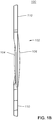
- FIGS. 1A-1B illustrate and example embodiment of an intraocular lens 100 having an extended depth of focus, according to certain embodiments of the present disclosure.
- IOL 100 includes an optic 102 having an anterior surface 104 and a posterior surface 106 that are disposed about an optical axis OA 108.
- IOL 100 may further include a plurality of haptics 110 generally operable to position and stabilize IOL 100 within the capsular bag of a patient's eye.
- the anterior surface 104 of optic 102 includes a first zone 112 extending from the optical axis 108 to a first radial boundary and a second zone 114 extending from the first radial boundary to the edge of the optic 102. Additionally, the first zone 112 may include an inner region 116 and an outer region 118 separated by a phase shift feature 120.
- the above-described surface features of optic 102 may produce varying amount of phase shift of light waves passing through optic 102 (depending upon the region of the optic 102 the light waves pass through), and constructive interference between the light waves having varying amounts of phase shift may produce an extended depth of focus.
- first and second zones 112, 114 are depicted and described as being located on anterior surface 104 of optic 102, the present disclosure contemplates that first and second zones 112, 114 may additionally or alternatively be located on posterior surface 106 of optic 102.
- phase shift feature 120 may include a ridge projecting anteriorly from the anterior surface 104 of optic 102. As a result, moving radially outward from the optical axis 108, phase shift feature 120 may result in two phase shift steps.
- the equation defining Z base may only include second, fourth, and sixth order coefficients.
- Eq. (2) and Eq. (3) generally define aspheric surface profiles
- the present disclosure contemplates that the constants includes in those equations may be selected such that they define a spheric profile.
- the base curvature of the first zone (Z base ) may be either spheric or aspheric.
- Z 2ps may be added to the base sag profile (Z base ) and may, in part, define the features of the phase shift region 120.
- the overall surface profile of optic 102 may be graphically represented as a plot of sag vs. radial distance from the optical axis 108, as shown in FIG. 2 .
- the sag values have been normalized by removing the contribution of Z base (i.e., the plotted sag value corresponds only to Z 2ps ).
- the sag profile is constant for the first zone 112 and the second zone 114.
- Eq. (1) defines the surface profile of the entire optic 102 as opposed to only the first zone 112 (meaning that, in Eq. (4), r 5 corresponds to the radius of the entire optic 102).
- FIG. 3 illustrates a through focus plot for the optic surface profile depicted in FIG. 2 as compared to the through focus plot for a standard aspheric optic (i.e., an optic having a surface profile defined only by Eq. (3) (Z base ) without the addition of Eq.(4) (Z 2ps )), according to certain embodiments of the present disclosure.
- a standard aspheric optic i.e., an optic having a surface profile defined only by Eq. (3) (Z base ) without the addition of Eq.(4) (Z 2ps )
- the base sag profile may be different for the first zone 112 and the second zone 114.
- base profiles defined in Eq. (6) above only include second, fourth, and sixth order coefficients, the present disclosure contemplates that those base profiles could alternatively be defined as including any suitable number of higher order coefficients (as in Eq. (1)).
- ⁇ 3 (as defined in Eq. (8)) may provide for a smooth transition between the first zone 112 and the second zone 112.
- the first zone 112 may be modified with a different base curvature (c), conic constant (k), and/or higher order coefficients (a 2 , a 4 , a 6 ) as compared to second zone 114 in order to shift the through focus curve in the myopic direction as compared to the through focus curve depicted in FIG. 3 .
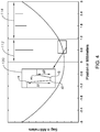
- FIG. 4 illustrates a plot of surface sag versus radial distance from the optical axis for an optic 102 having a surface profile defined by Eqs.
- the surface profile plotted in FIG. 4 assumes the following values: Table 1 r 1 (mm) 0.55 r 2 (mm) 0.65 r 3 (mm) 0.87 r 4 (mm) 1.05 r 5 (mm) 1.11 r 6 (mm) 3.00 ⁇ 1 ( ⁇ m) -1.02 ⁇ 2 ( ⁇ m) 0.59 c (1/mm) 19.05 k 5.99 a 2 (1/mm) 0 a4 (1/mm 3 ) 0 a 6 (1/mm 5 ) 0 c' (1/mm) 20.74 k' -43.56 a2'(1/mm) 0 a 4 '(1/mm 3 ) 0.00019 a 6 '(1/mm 5 ) -0.00002
- r 1 may fall in the range of 0.3mm to 0.7mm
- r 4 may fall in the range of 0.8mm to 1.2mm
- the distance between r 1 and r 2 may fall in the range of 0mm to 0.2mm
- the distance between r 3 and r 4 may fall in the range of 0mm to 0.2mm.
- ⁇ 1 may fall within the range of -1.5 ⁇ m and -0.5 ⁇ m and ⁇ 2 may fall within the range of 0.3 ⁇ m and 0.9 ⁇ m.
- FIG. 5 illustrates a through focus plot for the optic surface profile depicted in FIG. 4 as compared to the through focus plot for the optic depicted in FIG. 2 , according to certain embodiments of the present disclosure.
- modifying the first zone 112 with a different base curvature, conic constant, and/or higher order coefficients (1) rebalances the energy between intermediate and distance correction, and (2) shifts the through focus curve in the myopic direction (near target direction) as compared to the through focus curve for an optic in which the first zone 112 and the second zone 114 have the same base curvature.
- the optic 102 of an IOL 100 can be formed of a variety of biocompatible polymeric materials.
- suitable biocompatible materials include, without limitation, soft acrylic polymers, hydrogel, polymethymethacrylate, polysulfone, polystyrene, cellulose, acetate butyrate, or other biocompatible materials.
- the optic 102 may be formed of a soft acrylic polymer (crosslinked copolymer of 2-phenylethyl acrylate and 2-phenylethyl methacrylate) commonly known as Acrysof.
- the haptics 104 of the IOLs 100 can also be formed of suitable biocompatible materials, such as those discussed above. While in some cases, the optic 102 and haptics 104 of an IOL can be fabricated as an integral unit, in other cases they can be formed separately and joined together utilizing techniques known in the art.
Landscapes
- Health & Medical Sciences (AREA)
- Ophthalmology & Optometry (AREA)
- General Health & Medical Sciences (AREA)
- Animal Behavior & Ethology (AREA)
- Public Health (AREA)
- Engineering & Computer Science (AREA)
- Biomedical Technology (AREA)
- Heart & Thoracic Surgery (AREA)
- Vascular Medicine (AREA)
- Life Sciences & Earth Sciences (AREA)
- Oral & Maxillofacial Surgery (AREA)
- Cardiology (AREA)
- Transplantation (AREA)
- Veterinary Medicine (AREA)
- Physics & Mathematics (AREA)
- General Physics & Mathematics (AREA)
- Optics & Photonics (AREA)
- Prostheses (AREA)
- Eyeglasses (AREA)
- Materials For Medical Uses (AREA)
Abstract
Description
- This present disclosure relates generally ophthalmic lenses and, more particularly, to ophthalmic lenses having an extended depth of focus.
- Intraocular lenses (IOLs) are routinely implanted in patients' eyes during cataract surgery to replace the natural crystalline lens. The optical power of the natural crystalline lens can vary under the influence of the ciliary muscles to provide accommodation for viewing objects at different distances from the eye. Many IOLs, however, provide a monofocal power with no provision for accommodation. Multifocal IOLs are also known that provide a distance optical power as well as a near optical power (e.g., by employing diffractive structures), thereby providing a degree of pseudoaccommodation. There is, however, still a need for improved IOLs that can provide pseudo-accommodative optical power.
- The present disclosure generally concerns ophthalmic lenses (e.g., IOLs) that provide (1) controlled variation of multiple phase shifts within the pupil region to extend the depth-of-focus and (2) power adjustment in the central sub-area of the pupil region to shift the through-focus curve and to rebalance the energy between intermediate correction and the distance correction. In certain embodiments, an ophthalmic lens includes an optic having an anterior surface, a posterior surface, and an optical axis. At least one of the anterior surface and the posterior surface includes a first zone extending from the optical axis to a first radial boundary and a second zone extending from the first radial boundary to the edge of the optic. The first zone includes an inner region and an outer region separated by a phase shift feature, the phase shift comprising a ridge extending outwardly from the inner region and the outer region.
- For a more complete understanding of the present disclosure and the advantages thereof, reference is now made to the following description taken in conjunction with the accompanying drawings in which like reference numerals indicate like features and wherein:
-
FIGS. 1A-1B illustrate and example embodiment of an intraocular lens having an extended depth of focus, according to certain embodiments of the present disclosure; -
FIG. 2 illustrates an plot of surface sag versus radial distance from the optical axis for an exemplary optic having inner and outer zones with the same base curvature, according to certain embodiments of the present disclosure; -
FIG. 3 illustrates a through focus plot for the optic surface profile depicted inFIG. 2 as compared to the through focus plot for a standard aspheric optic, according to certain embodiments of the present disclosure; -
FIG. 4 illustrates a plot of surface sag versus radial distance from the optical axis for an exemplary optic having inner and outer zones with different base curvatures, according to certain embodiments of the present disclosure; and -
FIG. 5 illustrates a through focus plot for the optic surface profile depicted inFIG. 4 as compared to the through focus plot for the optic depicted inFIG. 2 , according to certain embodiments of the present disclosure. - The skilled person in the art will understand that the drawings, described below, are for illustration purposes only. The drawings are not intended to limit the scope of the applicant's disclosure in any way.
- The present disclosure is generally directed to an ophthalmic lens (such as an IOL) having a surface profile that produces a controlled variation of phase shifts in light waves passing through various regions of the lens in a manner that extends the depth-of-focus. In the following description, the lens features providing an extended depth of focus are described in connection with intraocular lenses (IOLs). However, the present disclosure contemplates that those features can also be applied to other ophthalmic lenses, such as contact lenses. As used herein, the term intraocular lens (and its abbreviation IOL) are used to describe lenses that are implanted into the interior of the eye to either replace the eye's natural lens or to otherwise augment vision regardless of whether or not the natural lens is removed.
-
FIGS. 1A-1B illustrate and example embodiment of anintraocular lens 100 having an extended depth of focus, according to certain embodiments of the present disclosure. IOL 100 includes an optic 102 having ananterior surface 104 and aposterior surface 106 that are disposed about anoptical axis OA 108.IOL 100 may further include a plurality ofhaptics 110 generally operable to position and stabilizeIOL 100 within the capsular bag of a patient's eye. - As shown in
FIGURE 1A , theanterior surface 104 ofoptic 102 includes afirst zone 112 extending from theoptical axis 108 to a first radial boundary and asecond zone 114 extending from the first radial boundary to the edge of the optic 102. Additionally, thefirst zone 112 may include aninner region 116 and anouter region 118 separated by aphase shift feature 120. In general, the above-described surface features of optic 102 may produce varying amount of phase shift of light waves passing through optic 102 (depending upon the region of theoptic 102 the light waves pass through), and constructive interference between the light waves having varying amounts of phase shift may produce an extended depth of focus. Although the above-described first andsecond zones anterior surface 104 of optic 102, the present disclosure contemplates that first andsecond zones posterior surface 106 of optic 102. - In certain embodiments,
phase shift feature 120 may include a ridge projecting anteriorly from theanterior surface 104 of optic 102. As a result, moving radially outward from theoptical axis 108,phase shift feature 120 may result in two phase shift steps. For example, the surface profile of the first zone may be defined by the following equation:
- In Eq. (1), Zbase may define a base sag profile for the first zone according to the following equation:

- r is a radial distance from the
optical axis 108; - c is a base curvature of the
first zone 112; - k is a conic constant; and
- a2, a4, a6, ... , and an are, respectively, second, fourth, sixth, ..., and nth order coefficients.
- In certain embodiments, the equation defining Zbase may only include second, fourth, and sixth order coefficients. In other words, Zbase may define a base sag profile for the first zone according to the following equation:

- Although Eq. (2) and Eq. (3) generally define aspheric surface profiles, the present disclosure contemplates that the constants includes in those equations may be selected such that they define a spheric profile. In other words, the base curvature of the first zone (Zbase) may be either spheric or aspheric.
- In Eq. (1), Z2ps may be added to the base sag profile (Zbase) and may, in part, define the features of the
phase shift region 120. For example, Z2ps may be defined by the following equation:
- r is a radial distance from the
optical axis 108; - r0 is the
optical axis 108; - the
inner region 116 extends from theoptical axis 108 to r1 - the
phase shift feature 120 extends from r1 to r4; - the
outer region 118 extends from r4 to r5; - Δ1 is a step height of the
phase shift 120 feature relative to theinner region 116; and - Δ2 is a step height of the phase shift feature relative to the
outer region 118. - The overall surface profile of optic 102, as defined by Eqs. (1)-(4), may be graphically represented as a plot of sag vs. radial distance from the
optical axis 108, as shown inFIG. 2 . In the plot ofFIG. 2 , the sag values have been normalized by removing the contribution of Zbase (i.e., the plotted sag value corresponds only to Z2ps). Additionally, in the plot ofFIG. 2 , the sag profile is constant for thefirst zone 112 and thesecond zone 114. In other words, it is assumed that Eq. (1) defines the surface profile of theentire optic 102 as opposed to only the first zone 112 (meaning that, in Eq. (4), r5 corresponds to the radius of the entire optic 102). -
FIG. 3 illustrates a through focus plot for the optic surface profile depicted inFIG. 2 as compared to the through focus plot for a standard aspheric optic (i.e., an optic having a surface profile defined only by Eq. (3) (Zbase) without the addition of Eq.(4) (Z2ps)), according to certain embodiments of the present disclosure. As is illustrated, the addition of the surface profile depicted inFIG. 2 (including thephase shift feature 120 represented by Z2ps) results in a wider depth of focus as compared to a standard aspheric lens. - In certain embodiments, the base sag profile may be different for the
first zone 112 and thesecond zone 114. For example, the surface profile of the optic 102 may be defined by the following equation:


- r is a radial distance from the
optical axis 108; - r0 is the
optical axis 108; - the
first zone 112 extends fromoptical axis 108 to r5, with theinner region 116 extending from theoptical axis 108 to r1, thephase shift feature 120 extending from r1 to r4, and theouter region 118 extending from r4 to r5; - the
second zone 114 extends from r5 to r6; - c is a base curvature of the
first zone 112; - k is a conic constant of the
first zone 112; and - a2, a4, and a6 are, respectively, second, fourth, and sixth order coefficients of the
first zone 112; - c' is a base curvature of the
second zone 114; - k' is a conic constant of the
second zone 114; and - a2', a4', and a6 are, respectively, second, fourth, and sixth order coefficients of the
second zone 114; - Δ1 is a step height of the
phase shift feature 120 relative to theinner region 116; and - Δ2 is a step height of the
phase shift feature 120 relative to theouter region 118. - Although base profiles defined in Eq. (6) above only include second, fourth, and sixth order coefficients, the present disclosure contemplates that those base profiles could alternatively be defined as including any suitable number of higher order coefficients (as in Eq. (1)).
- Because the
first zone 112 and thesecond zone 114 have different base sag profiles, Δ3 (as defined in Eq. (8)) may provide for a smooth transition between thefirst zone 112 and thesecond zone 112. For example, thefirst zone 112 may be modified with a different base curvature (c), conic constant (k), and/or higher order coefficients (a2, a4, a6) as compared tosecond zone 114 in order to shift the through focus curve in the myopic direction as compared to the through focus curve depicted inFIG. 3 .FIG. 4 illustrates a plot of surface sag versus radial distance from the optical axis for an optic 102 having a surface profile defined by Eqs. (5) through (8), according to certain embodiments of the present disclosure. The surface profile plotted inFIG. 4 assumes the following values:Table 1 r1 (mm) 0.55 r2 (mm) 0.65 r3 (mm) 0.87 r4 (mm) 1.05 r5 (mm) 1.11 r6 (mm) 3.00 Δ1 (µm) -1.02 Δ2 (µm) 0.59 c (1/mm) 19.05 k 5.99 a2 (1/mm) 0 a4 (1/mm3) 0 a6 (1/mm5) 0 c' (1/mm) 20.74 k' -43.56 a2'(1/mm) 0 a4'(1/mm3) 0.00019 a6'(1/mm5) -0.00002 - The values listed in Table 1 are provided for exemplary purposes only and the present disclosure contemplates that each of the values may have a range of different values. As examples, the present disclosure contemplates that r1 may fall in the range of 0.3mm to 0.7mm, r4 may fall in the range of 0.8mm to 1.2mm, the distance between r1 and r2 may fall in the range of 0mm to 0.2mm, and the distance between r3 and r4 may fall in the range of 0mm to 0.2mm. As additional examples, the present disclosure contemplates that Δ1 may fall within the range of -1.5µm and -0.5µm and Δ2 may fall within the range of 0.3µm and 0.9µm.
-
FIG. 5 illustrates a through focus plot for the optic surface profile depicted inFIG. 4 as compared to the through focus plot for the optic depicted inFIG. 2 , according to certain embodiments of the present disclosure. As discussed above, modifying thefirst zone 112 with a different base curvature, conic constant, and/or higher order coefficients (1) rebalances the energy between intermediate and distance correction, and (2) shifts the through focus curve in the myopic direction (near target direction) as compared to the through focus curve for an optic in which thefirst zone 112 and thesecond zone 114 have the same base curvature. - A variety of techniques and materials can be employed to fabricate the above-described
IOLs 100. For example, theoptic 102 of anIOL 100 can be formed of a variety of biocompatible polymeric materials. Some suitable biocompatible materials include, without limitation, soft acrylic polymers, hydrogel, polymethymethacrylate, polysulfone, polystyrene, cellulose, acetate butyrate, or other biocompatible materials. By way of example, in one embodiment, the optic 102 may be formed of a soft acrylic polymer (crosslinked copolymer of 2-phenylethyl acrylate and 2-phenylethyl methacrylate) commonly known as Acrysof. Thehaptics 104 of theIOLs 100 can also be formed of suitable biocompatible materials, such as those discussed above. While in some cases, the optic 102 andhaptics 104 of an IOL can be fabricated as an integral unit, in other cases they can be formed separately and joined together utilizing techniques known in the art. - It will be appreciated that various of the above-disclosed and other features and functions, or alternatives thereof, may be desirably combined into many other different systems or applications. It will also be appreciated that various presently unforeseen or unanticipated alternatives, modifications, variations or improvements therein may be subsequently made by those skilled in the art which alternatives, variations and improvements are also intended to be encompassed by the following claims.
- The specification also provides arrangements according to one or more of the following clauses:
- 1. An ophthalmic lens, comprising
an optic comprising an anterior surface, a posterior surface, and an optical axis, at least one of the anterior surface and the posterior surface comprising:- a first zone extending from the optical axis to a first radial boundary; and
- a second zone extending from the first radial boundary to the edge of the optic;
- 2. The ophthalmic lens of
clause 1, wherein the inner region and the outer region have the same optical power. - 3. The ophthalmic lens of
clause 1, wherein the first zone and the second zone have different aspheric profiles. - 4. The ophthalmic lens of
clause 1, wherein a surface profile of the first zone is defined as follows:
- 5. The ophthalmic lens of clause 4, wherein:

- r is a radial distance from the optical axis;
- c is a base curvature of the first zone;
- k is a conic constant; and
- a2, a4, and a6 are, respectively, second, fourth, and sixth order coefficients.
- 6. The ophthalmic lens of clause 4, wherein:

- r is a radial distance from the optical axis;
- r0 is the optical axis;
- the inner region extends from the optical axis to r1
- the phase shift feature extends from r1 to r4;
- the outer region extends from r4 to r5;
- Δ1 is a step height of the phase shift feature relative to the inner region; and
- Δ2 is a step height of the phase shift feature relative to the outer region.
- 7. The ophthalmic lens of clause 4, wherein a surface profile of the second zone is defined as follows:

- 8. The ophthalmic lens of clause 4, wherein Zbase defines a spheric surface profile.
- 9. The ophthalmic lens of clause 4, wherein Zbase defines an aspheric surface profile.
- 10. The ophthalmic lens of
clause 1, wherein a surface profile of the optic is defined as follows:


- r is a radial distance from the optical axis;
- r0 is the optical axis;
- the first zone extends from optical axis to r5, with the inner region extending from the optical axis to r1, the phase shift feature extending from r1 to r4, and the outer region extending from r4 to r5;
- the second zone extends from r5 to r6;
- c is a base curvature of the first zone;
- k is a conic constant of the first zone; and
- a2, a4, and a6 are, respectively, second, fourth, and sixth order coefficients of the first zone;
- c' is a base curvature of the second zone;
- k' is a conic constant of the second zone; and
- a2', a4', and a6 are, respectively, second, fourth, and sixth order coefficients of the second zone;
- Δ1 is a step height of the phase shift feature relative to the inner region; and
- Δ2 is a step height of the phase shift feature relative to the outer region.
- 11. The ophthalmic lens of clause 10, wherein:
- at least one of the following c ≠ c', k ≠ k', a2 ≠ a2', a4 ≠ a4', and a6 ≠ a6' is true; and
- Δ3 is a constant added to the base curvature of the second zone to ensure continuity between the first zone and the second zone.
- 12. The ophthalmic lens of clause 11, wherein:

Claims (7)
- An ophthalmic lens, comprising:an optic comprising an anterior surface, a posterior surface, and an optical axis, at least one of the anterior surface and the posterior surface comprising:a first zone extending from the optical axis to a first radial boundary; anda second zone extending from the first radial boundary to the edge of the optic;wherein:the first zone comprises an inner region and an outer region having a first curvature; anda phase shift feature separating the inner region and the outer region, the phase shift feature comprising a ridge of increased thickness relative to an adjacent portion of the inner region, the ridge comprising a ridge surface, a first phase shift step extending outwardly from the inner region to the ridge surface, and a second phase shift step extending inwardly from the ridge surface to the outer region.
- The ophthalmic lens of claim 1, wherein the inner region and the outer region have the same optical power.
- The ophthalmic lens of claim 1, wherein a surface profile of the first zone is defined as follows:

 r is a radial distance from the optical axis;c is a base curvature of the first zone;k is a conic constant; anda2, a4, and a6 are, respectively, second, fourth, and sixth order coefficients; andwherein
 r is a radial distance from the optical axis;r0 is the optical axis;the inner region extends from the optical axis to r1;the phase shift feature extends from r1 to r4;an outer region of the first zone extends from r4 to r5;Δ1 is a step height of the phase shift feature relative to the inner region; andΔ2 is a step height of the phase shift feature relative to the outer region.
 - The ophthalmic lens of claim 3, wherein a surface profile of the second zone is defined as follows:

- The ophthalmic lens of claim 1, wherein a step height of the first phase shift step is greater than a step height of the second phase shift step.
- The ophthalmic lens of claim 1, wherein the ridge surface has the first curvature.
- The ophthalmic lens of claim 1, wherein the first curvature comprises an aspheric profile.
Priority Applications (1)
| Application Number | Priority Date | Filing Date | Title |
|---|---|---|---|
| EP23201411.8A EP4302728A3 (en) | 2016-02-29 | 2017-02-15 | Ophthalmic lens having an extended depth of focus |
Applications Claiming Priority (3)
| Application Number | Priority Date | Filing Date | Title |
|---|---|---|---|
| US15/055,993 US9968440B2 (en) | 2016-02-29 | 2016-02-29 | Ophthalmic lens having an extended depth of focus |
| PCT/IB2017/050849 WO2017149401A1 (en) | 2016-02-29 | 2017-02-15 | Ophthalmic lens having an extended depth of focus |
| EP17707678.3A EP3423003B1 (en) | 2016-02-29 | 2017-02-15 | Ophthalmic lens having an extended depth of focus |
Related Parent Applications (1)
| Application Number | Title | Priority Date | Filing Date |
|---|---|---|---|
| EP17707678.3A Division EP3423003B1 (en) | 2016-02-29 | 2017-02-15 | Ophthalmic lens having an extended depth of focus |
Related Child Applications (1)
| Application Number | Title | Priority Date | Filing Date |
|---|---|---|---|
| EP23201411.8A Division EP4302728A3 (en) | 2016-02-29 | 2017-02-15 | Ophthalmic lens having an extended depth of focus |
Publications (2)
| Publication Number | Publication Date |
|---|---|
| EP3792684A1 true EP3792684A1 (en) | 2021-03-17 |
| EP3792684B1 EP3792684B1 (en) | 2023-10-04 |
Family
ID=58185571
Family Applications (3)
| Application Number | Title | Priority Date | Filing Date |
|---|---|---|---|
| EP20196792.4A Active EP3792684B1 (en) | 2016-02-29 | 2017-02-15 | Ophthalmic lens having an extended depth of focus |
| EP23201411.8A Pending EP4302728A3 (en) | 2016-02-29 | 2017-02-15 | Ophthalmic lens having an extended depth of focus |
| EP17707678.3A Active EP3423003B1 (en) | 2016-02-29 | 2017-02-15 | Ophthalmic lens having an extended depth of focus |
Family Applications After (2)
| Application Number | Title | Priority Date | Filing Date |
|---|---|---|---|
| EP23201411.8A Pending EP4302728A3 (en) | 2016-02-29 | 2017-02-15 | Ophthalmic lens having an extended depth of focus |
| EP17707678.3A Active EP3423003B1 (en) | 2016-02-29 | 2017-02-15 | Ophthalmic lens having an extended depth of focus |
Country Status (13)
| Country | Link |
|---|---|
| US (1) | US9968440B2 (en) |
| EP (3) | EP3792684B1 (en) |
| JP (4) | JP6989512B2 (en) |
| KR (4) | KR102659954B1 (en) |
| CN (2) | CN112932734B (en) |
| AU (3) | AU2017225591B2 (en) |
| BR (1) | BR112018016183B1 (en) |
| CA (1) | CA3010921A1 (en) |
| ES (2) | ES2836725T3 (en) |
| MX (1) | MX2018009350A (en) |
| RU (1) | RU2740081C2 (en) |
| TW (1) | TW201734579A (en) |
| WO (1) | WO2017149401A1 (en) |
Families Citing this family (17)
| Publication number | Priority date | Publication date | Assignee | Title |
|---|---|---|---|---|
| CN107072779B (en) | 2014-09-09 | 2020-01-14 | 斯塔尔外科有限公司 | Ocular implant with extended depth of field and enhanced distance vision |
| US12127934B2 (en) | 2014-09-09 | 2024-10-29 | Staar Surgical Company | Method of Providing Modified Monovision to a Subject with a First Lens and a Second Lens |
| US11083566B2 (en) * | 2016-02-29 | 2021-08-10 | Alcon Inc. | Ophthalmic lens having an extended depth of focus |
| CN109070506B (en) | 2016-03-09 | 2021-06-29 | 斯塔尔外科有限公司 | Ophthalmic implants with extended depth of field and enhanced distance vision |
| ES2956033T3 (en) | 2018-08-17 | 2023-12-12 | Staar Surgical Co | Polymeric composition exhibiting refractive index nanogradient |
| JP7815106B2 (en) * | 2019-08-23 | 2026-02-17 | ブリエン ホールデン ビジョン インスティチュート リミテッド | Ophthalmic lens for reducing, minimizing, and/or eliminating interference of out-of-focus light with a focused image |
| CA3169919A1 (en) * | 2020-04-16 | 2021-10-21 | Myoung-Taek Choi | Ophthalmic lenses having an extended depth of focus for improving intermediate vision |
| EP3958045A1 (en) * | 2020-08-18 | 2022-02-23 | Hoya Corporation | Ophthalmic lens |
| AU2021356283A1 (en) * | 2020-10-08 | 2023-03-30 | Alcon Inc. | Ophthalmic lens with phase-shift structure and method |
| BR112023016585A2 (en) | 2021-02-19 | 2023-11-07 | Vsy Biyoteknoloji Ve Ilac Sanayi A S | MULTIFOCAL OPHTHALMIC LENS ARRANGEMENT TO PROVIDE LONG, INTERMEDIATE AND NEAR VISION |
| US12239529B2 (en) | 2021-03-09 | 2025-03-04 | Amo Groningen B.V. | Refractive extended depth of focus intraocular lens, and methods of use and manufacture |
| EP4355262A1 (en) * | 2021-06-16 | 2024-04-24 | Alcon Inc. | Ophthalmic lenses for balancing coma aberrations |
| CN113693780B (en) * | 2021-08-16 | 2022-08-09 | 麦得科科技有限公司 | Ophthalmic lens with extended depth of field |
| US12393054B2 (en) | 2021-08-31 | 2025-08-19 | Alcon Inc. | Multifocal ophthalmic lens with extended depth-of-focus |
| JP2024537856A (en) | 2021-10-04 | 2024-10-16 | スター サージカル カンパニー | Ophthalmic implants for correcting vision with adjustable optics and methods for making and using same - Patents.com |
| CN118785870A (en) * | 2022-01-14 | 2024-10-15 | Ast产品公司 | Design, manufacture and application of non-spherical phase ring structure lens |
| EP4724009A1 (en) | 2023-06-09 | 2026-04-15 | VSY Biyoteknoloji Ve Ilac Sanayi Anonim Sirketi | An extended depth of field lens |
Citations (3)
| Publication number | Priority date | Publication date | Assignee | Title |
|---|---|---|---|---|
| US20060034003A1 (en) * | 2004-08-16 | 2006-02-16 | Xceed Imaging Ltd. | Optical method and system for extended depth of focus |
| US7073906B1 (en) * | 2005-05-12 | 2006-07-11 | Valdemar Portney | Aspherical diffractive ophthalmic lens |
| US20100161051A1 (en) * | 2008-12-18 | 2010-06-24 | Xin Hong | Intraocular lens with extended depth of focus |
Family Cites Families (27)
| Publication number | Priority date | Publication date | Assignee | Title |
|---|---|---|---|---|
| US6554859B1 (en) * | 2000-05-03 | 2003-04-29 | Advanced Medical Optics, Inc. | Accommodating, reduced ADD power multifocal intraocular lenses |
| US6536898B1 (en) | 2000-09-15 | 2003-03-25 | The Regents Of The University Of Colorado | Extended depth of field optics for human vision |
| SE0101293D0 (en) * | 2001-04-11 | 2001-04-11 | Pharmacia Groningen Bv | Technical field of the invention |
| US7365917B2 (en) | 2004-08-16 | 2008-04-29 | Xceed Imaging Ltd. | Optical method and system for extended depth of focus |
| US20070171362A1 (en) * | 2004-12-01 | 2007-07-26 | Simpson Michael J | Truncated diffractive intraocular lenses |
| US20060116764A1 (en) * | 2004-12-01 | 2006-06-01 | Simpson Michael J | Apodized aspheric diffractive lenses |
| CN101223470A (en) * | 2005-05-12 | 2008-07-16 | 瓦尔德马·波特尼 | Aspheric diffractive ophthalmic lens |
| US9216080B2 (en) | 2007-08-27 | 2015-12-22 | Amo Groningen B.V. | Toric lens with decreased sensitivity to cylinder power and rotation and method of using the same |
| US8740978B2 (en) * | 2007-08-27 | 2014-06-03 | Amo Regional Holdings | Intraocular lens having extended depth of focus |
| US8974526B2 (en) * | 2007-08-27 | 2015-03-10 | Amo Groningen B.V. | Multizonal lens with extended depth of focus |
| US20090088840A1 (en) * | 2007-10-02 | 2009-04-02 | Simpson Michael J | Zonal diffractive multifocal intraocular lenses |
| US7998198B2 (en) * | 2008-02-07 | 2011-08-16 | Novartis Ag | Accommodative IOL with dynamic spherical aberration |
| US20100016965A1 (en) * | 2008-07-15 | 2010-01-21 | Xin Hong | Accommodative IOL with Toric Optic and Extended Depth of Focus |
| EP2307923A1 (en) * | 2008-07-15 | 2011-04-13 | Alcon, Inc. | Extended depth of focus (edof) lens to increase pseudo-accommodation by utilizing pupil dynamics |
| TWI523647B (en) * | 2009-07-17 | 2016-03-01 | 艾爾康股份有限公司 | An extended depth of focus (edof) lens to increase pseudo-accommodation by utilizing pupil dynamics |
| CN104777628B (en) * | 2009-09-01 | 2018-04-17 | 阿瑟·布拉德利 | Multifocal correction providing improved visual quality |
| CA2784782C (en) * | 2009-12-18 | 2018-02-27 | Hendrik A. Weeber | Limited echelette lens, systems and methods |
| CA2820012A1 (en) | 2010-09-13 | 2012-03-22 | The Regents Of The University Of Colorado, A Body Corporate | Extended depth of field optics with variable pupil diameter |
| US9817246B2 (en) * | 2010-12-01 | 2017-11-14 | Amo Groningen B.V. | Multifocal lens having an optical add power progression, and a system and method of providing same |
| US8894204B2 (en) * | 2010-12-17 | 2014-11-25 | Abbott Medical Optics Inc. | Ophthalmic lens, systems and methods having at least one rotationally asymmetric diffractive structure |
| US8556417B2 (en) * | 2012-02-02 | 2013-10-15 | Novartis Ag | Apodized hybrid diffractive-refractive IOL for pseudo-accommodation |
| BR112015004617A2 (en) * | 2012-08-31 | 2017-07-04 | Amo Groningen Bv | systems and methods for extended multi-lens lens extended focus depth |
| CN104918580B (en) * | 2012-12-18 | 2017-10-27 | 诺华股份有限公司 | Methods and systems for providing intraocular lenses with improved depth of field |
| US10379379B2 (en) * | 2013-03-07 | 2019-08-13 | Amo Groningen B.V. | Lens providing extended depth of focus and method relating to same |
| US9335564B2 (en) * | 2014-05-15 | 2016-05-10 | Novartis Ag | Multifocal diffractive ophthalmic lens using suppressed diffractive order |
| CN107072779B (en) * | 2014-09-09 | 2020-01-14 | 斯塔尔外科有限公司 | Ocular implant with extended depth of field and enhanced distance vision |
| CN104783925B (en) * | 2015-01-09 | 2017-01-18 | 爱博诺德(北京)医疗科技有限公司 | Multi-focal artificial lens |
-
2016
- 2016-02-29 US US15/055,993 patent/US9968440B2/en active Active
-
2017
- 2017-02-14 TW TW106104803A patent/TW201734579A/en unknown
- 2017-02-15 EP EP20196792.4A patent/EP3792684B1/en active Active
- 2017-02-15 KR KR1020247000182A patent/KR102659954B1/en active Active
- 2017-02-15 ES ES17707678T patent/ES2836725T3/en active Active
- 2017-02-15 MX MX2018009350A patent/MX2018009350A/en unknown
- 2017-02-15 AU AU2017225591A patent/AU2017225591B2/en active Active
- 2017-02-15 JP JP2018543198A patent/JP6989512B2/en active Active
- 2017-02-15 WO PCT/IB2017/050849 patent/WO2017149401A1/en not_active Ceased
- 2017-02-15 CA CA3010921A patent/CA3010921A1/en active Pending
- 2017-02-15 KR KR1020187022058A patent/KR102622840B1/en active Active
- 2017-02-15 ES ES20196792T patent/ES2965314T3/en active Active
- 2017-02-15 CN CN202110114955.XA patent/CN112932734B/en active Active
- 2017-02-15 RU RU2018134033A patent/RU2740081C2/en active
- 2017-02-15 EP EP23201411.8A patent/EP4302728A3/en active Pending
- 2017-02-15 BR BR112018016183-7A patent/BR112018016183B1/en active IP Right Grant
- 2017-02-15 EP EP17707678.3A patent/EP3423003B1/en active Active
- 2017-02-15 KR KR1020247012788A patent/KR102915313B1/en active Active
- 2017-02-15 KR KR1020267001285A patent/KR20260016010A/en active Pending
- 2017-02-15 CN CN201780011250.7A patent/CN108697501B/en active Active
-
2021
- 2021-12-02 JP JP2021196174A patent/JP7204867B2/en active Active
-
2022
- 2022-09-28 AU AU2022241524A patent/AU2022241524B2/en active Active
- 2022-12-27 JP JP2022209482A patent/JP7601850B2/en active Active
-
2024
- 2024-12-05 JP JP2024212044A patent/JP2025023283A/en active Pending
-
2025
- 2025-02-05 AU AU2025200788A patent/AU2025200788A1/en active Pending
Patent Citations (3)
| Publication number | Priority date | Publication date | Assignee | Title |
|---|---|---|---|---|
| US20060034003A1 (en) * | 2004-08-16 | 2006-02-16 | Xceed Imaging Ltd. | Optical method and system for extended depth of focus |
| US7073906B1 (en) * | 2005-05-12 | 2006-07-11 | Valdemar Portney | Aspherical diffractive ophthalmic lens |
| US20100161051A1 (en) * | 2008-12-18 | 2010-06-24 | Xin Hong | Intraocular lens with extended depth of focus |
Also Published As
Similar Documents
| Publication | Publication Date | Title |
|---|---|---|
| EP3423003B1 (en) | Ophthalmic lens having an extended depth of focus | |
| US20250082462A1 (en) | Ophthalmic lens having an extended depth of focus | |
| US20100016965A1 (en) | Accommodative IOL with Toric Optic and Extended Depth of Focus | |
| US9918831B2 (en) | Aspheric optical lenses and associated systems and methods | |
| NZ578748A (en) | Apodized differactive IOL with frustrated differactive region | |
| US12396842B2 (en) | Ophthalmic lenses having an extended depth of focus for improving intermediate vision | |
| US20250161026A1 (en) | Lens with Extended Depth of Focus by Inducing an Excess of Longitudinal Chromatic Aberration | |
| RU2828225C2 (en) | Ophthalmic lens with increased depth of focus |
Legal Events
| Date | Code | Title | Description |
|---|---|---|---|
| PUAI | Public reference made under article 153(3) epc to a published international application that has entered the european phase |
Free format text: ORIGINAL CODE: 0009012 |
|
| STAA | Information on the status of an ep patent application or granted ep patent |
Free format text: STATUS: THE APPLICATION HAS BEEN PUBLISHED |
|
| AC | Divisional application: reference to earlier application |
Ref document number: 3423003 Country of ref document: EP Kind code of ref document: P |
|
| AK | Designated contracting states |
Kind code of ref document: A1 Designated state(s): AL AT BE BG CH CY CZ DE DK EE ES FI FR GB GR HR HU IE IS IT LI LT LU LV MC MK MT NL NO PL PT RO RS SE SI SK SM TR |
|
| STAA | Information on the status of an ep patent application or granted ep patent |
Free format text: STATUS: REQUEST FOR EXAMINATION WAS MADE |
|
| 17P | Request for examination filed |
Effective date: 20210916 |
|
| RBV | Designated contracting states (corrected) |
Designated state(s): AL AT BE BG CH CY CZ DE DK EE ES FI FR GB GR HR HU IE IS IT LI LT LU LV MC MK MT NL NO PL PT RO RS SE SI SK SM TR |
|
| GRAP | Despatch of communication of intention to grant a patent |
Free format text: ORIGINAL CODE: EPIDOSNIGR1 |
|
| STAA | Information on the status of an ep patent application or granted ep patent |
Free format text: STATUS: GRANT OF PATENT IS INTENDED |
|
| INTG | Intention to grant announced |
Effective date: 20230425 |
|
| P01 | Opt-out of the competence of the unified patent court (upc) registered |
Effective date: 20230507 |
|
| GRAS | Grant fee paid |
Free format text: ORIGINAL CODE: EPIDOSNIGR3 |
|
| GRAA | (expected) grant |
Free format text: ORIGINAL CODE: 0009210 |
|
| STAA | Information on the status of an ep patent application or granted ep patent |
Free format text: STATUS: THE PATENT HAS BEEN GRANTED |
|
| AC | Divisional application: reference to earlier application |
Ref document number: 3423003 Country of ref document: EP Kind code of ref document: P |
|
| AK | Designated contracting states |
Kind code of ref document: B1 Designated state(s): AL AT BE BG CH CY CZ DE DK EE ES FI FR GB GR HR HU IE IS IT LI LT LU LV MC MK MT NL NO PL PT RO RS SE SI SK SM TR |
|
| REG | Reference to a national code |
Ref country code: GB Ref legal event code: FG4D |
|
| REG | Reference to a national code |
Ref country code: CH Ref legal event code: EP |
|
| REG | Reference to a national code |
Ref country code: IE Ref legal event code: FG4D |
|
| REG | Reference to a national code |
Ref country code: DE Ref legal event code: R096 Ref document number: 602017075098 Country of ref document: DE |
|
| REG | Reference to a national code |
Ref country code: NL Ref legal event code: FP |
|
| REG | Reference to a national code |
Ref country code: LT Ref legal event code: MG9D |
|
| REG | Reference to a national code |
Ref country code: AT Ref legal event code: MK05 Ref document number: 1618336 Country of ref document: AT Kind code of ref document: T Effective date: 20231004 |
|
| PG25 | Lapsed in a contracting state [announced via postgrant information from national office to epo] |
Ref country code: GR Free format text: LAPSE BECAUSE OF FAILURE TO SUBMIT A TRANSLATION OF THE DESCRIPTION OR TO PAY THE FEE WITHIN THE PRESCRIBED TIME-LIMIT Effective date: 20240105 |
|
| PG25 | Lapsed in a contracting state [announced via postgrant information from national office to epo] |
Ref country code: IS Free format text: LAPSE BECAUSE OF FAILURE TO SUBMIT A TRANSLATION OF THE DESCRIPTION OR TO PAY THE FEE WITHIN THE PRESCRIBED TIME-LIMIT Effective date: 20240204 |
|
| REG | Reference to a national code |
Ref country code: ES Ref legal event code: FG2A Ref document number: 2965314 Country of ref document: ES Kind code of ref document: T3 Effective date: 20240412 |
|
| PG25 | Lapsed in a contracting state [announced via postgrant information from national office to epo] |
Ref country code: LT Free format text: LAPSE BECAUSE OF FAILURE TO SUBMIT A TRANSLATION OF THE DESCRIPTION OR TO PAY THE FEE WITHIN THE PRESCRIBED TIME-LIMIT Effective date: 20231004 |
|
| PG25 | Lapsed in a contracting state [announced via postgrant information from national office to epo] |
Ref country code: AT Free format text: LAPSE BECAUSE OF FAILURE TO SUBMIT A TRANSLATION OF THE DESCRIPTION OR TO PAY THE FEE WITHIN THE PRESCRIBED TIME-LIMIT Effective date: 20231004 |
|
| PG25 | Lapsed in a contracting state [announced via postgrant information from national office to epo] |
Ref country code: LT Free format text: LAPSE BECAUSE OF FAILURE TO SUBMIT A TRANSLATION OF THE DESCRIPTION OR TO PAY THE FEE WITHIN THE PRESCRIBED TIME-LIMIT Effective date: 20231004 Ref country code: IS Free format text: LAPSE BECAUSE OF FAILURE TO SUBMIT A TRANSLATION OF THE DESCRIPTION OR TO PAY THE FEE WITHIN THE PRESCRIBED TIME-LIMIT Effective date: 20240204 Ref country code: GR Free format text: LAPSE BECAUSE OF FAILURE TO SUBMIT A TRANSLATION OF THE DESCRIPTION OR TO PAY THE FEE WITHIN THE PRESCRIBED TIME-LIMIT Effective date: 20240105 Ref country code: BG Free format text: LAPSE BECAUSE OF FAILURE TO SUBMIT A TRANSLATION OF THE DESCRIPTION OR TO PAY THE FEE WITHIN THE PRESCRIBED TIME-LIMIT Effective date: 20240104 Ref country code: AT Free format text: LAPSE BECAUSE OF FAILURE TO SUBMIT A TRANSLATION OF THE DESCRIPTION OR TO PAY THE FEE WITHIN THE PRESCRIBED TIME-LIMIT Effective date: 20231004 Ref country code: PT Free format text: LAPSE BECAUSE OF FAILURE TO SUBMIT A TRANSLATION OF THE DESCRIPTION OR TO PAY THE FEE WITHIN THE PRESCRIBED TIME-LIMIT Effective date: 20240205 |
|
| PG25 | Lapsed in a contracting state [announced via postgrant information from national office to epo] |
Ref country code: SE Free format text: LAPSE BECAUSE OF FAILURE TO SUBMIT A TRANSLATION OF THE DESCRIPTION OR TO PAY THE FEE WITHIN THE PRESCRIBED TIME-LIMIT Effective date: 20231004 Ref country code: RS Free format text: LAPSE BECAUSE OF FAILURE TO SUBMIT A TRANSLATION OF THE DESCRIPTION OR TO PAY THE FEE WITHIN THE PRESCRIBED TIME-LIMIT Effective date: 20231004 Ref country code: PL Free format text: LAPSE BECAUSE OF FAILURE TO SUBMIT A TRANSLATION OF THE DESCRIPTION OR TO PAY THE FEE WITHIN THE PRESCRIBED TIME-LIMIT Effective date: 20231004 Ref country code: NO Free format text: LAPSE BECAUSE OF FAILURE TO SUBMIT A TRANSLATION OF THE DESCRIPTION OR TO PAY THE FEE WITHIN THE PRESCRIBED TIME-LIMIT Effective date: 20240104 Ref country code: LV Free format text: LAPSE BECAUSE OF FAILURE TO SUBMIT A TRANSLATION OF THE DESCRIPTION OR TO PAY THE FEE WITHIN THE PRESCRIBED TIME-LIMIT Effective date: 20231004 Ref country code: HR Free format text: LAPSE BECAUSE OF FAILURE TO SUBMIT A TRANSLATION OF THE DESCRIPTION OR TO PAY THE FEE WITHIN THE PRESCRIBED TIME-LIMIT Effective date: 20231004 |
|
| REG | Reference to a national code |
Ref country code: DE Ref legal event code: R097 Ref document number: 602017075098 Country of ref document: DE |
|
| PG25 | Lapsed in a contracting state [announced via postgrant information from national office to epo] |
Ref country code: DK Free format text: LAPSE BECAUSE OF FAILURE TO SUBMIT A TRANSLATION OF THE DESCRIPTION OR TO PAY THE FEE WITHIN THE PRESCRIBED TIME-LIMIT Effective date: 20231004 |
|
| PG25 | Lapsed in a contracting state [announced via postgrant information from national office to epo] |
Ref country code: CZ Free format text: LAPSE BECAUSE OF FAILURE TO SUBMIT A TRANSLATION OF THE DESCRIPTION OR TO PAY THE FEE WITHIN THE PRESCRIBED TIME-LIMIT Effective date: 20231004 |
|
| PG25 | Lapsed in a contracting state [announced via postgrant information from national office to epo] |
Ref country code: SK Free format text: LAPSE BECAUSE OF FAILURE TO SUBMIT A TRANSLATION OF THE DESCRIPTION OR TO PAY THE FEE WITHIN THE PRESCRIBED TIME-LIMIT Effective date: 20231004 |
|
| PG25 | Lapsed in a contracting state [announced via postgrant information from national office to epo] |
Ref country code: SM Free format text: LAPSE BECAUSE OF FAILURE TO SUBMIT A TRANSLATION OF THE DESCRIPTION OR TO PAY THE FEE WITHIN THE PRESCRIBED TIME-LIMIT Effective date: 20231004 Ref country code: SK Free format text: LAPSE BECAUSE OF FAILURE TO SUBMIT A TRANSLATION OF THE DESCRIPTION OR TO PAY THE FEE WITHIN THE PRESCRIBED TIME-LIMIT Effective date: 20231004 Ref country code: RO Free format text: LAPSE BECAUSE OF FAILURE TO SUBMIT A TRANSLATION OF THE DESCRIPTION OR TO PAY THE FEE WITHIN THE PRESCRIBED TIME-LIMIT Effective date: 20231004 Ref country code: EE Free format text: LAPSE BECAUSE OF FAILURE TO SUBMIT A TRANSLATION OF THE DESCRIPTION OR TO PAY THE FEE WITHIN THE PRESCRIBED TIME-LIMIT Effective date: 20231004 Ref country code: DK Free format text: LAPSE BECAUSE OF FAILURE TO SUBMIT A TRANSLATION OF THE DESCRIPTION OR TO PAY THE FEE WITHIN THE PRESCRIBED TIME-LIMIT Effective date: 20231004 Ref country code: CZ Free format text: LAPSE BECAUSE OF FAILURE TO SUBMIT A TRANSLATION OF THE DESCRIPTION OR TO PAY THE FEE WITHIN THE PRESCRIBED TIME-LIMIT Effective date: 20231004 |
|
| PLBE | No opposition filed within time limit |
Free format text: ORIGINAL CODE: 0009261 |
|
| STAA | Information on the status of an ep patent application or granted ep patent |
Free format text: STATUS: NO OPPOSITION FILED WITHIN TIME LIMIT |
|
| 26N | No opposition filed |
Effective date: 20240705 |
|
| PG25 | Lapsed in a contracting state [announced via postgrant information from national office to epo] |
Ref country code: MC Free format text: LAPSE BECAUSE OF FAILURE TO SUBMIT A TRANSLATION OF THE DESCRIPTION OR TO PAY THE FEE WITHIN THE PRESCRIBED TIME-LIMIT Effective date: 20231004 |
|
| PG25 | Lapsed in a contracting state [announced via postgrant information from national office to epo] |
Ref country code: LU Free format text: LAPSE BECAUSE OF NON-PAYMENT OF DUE FEES Effective date: 20240215 |
|
| PG25 | Lapsed in a contracting state [announced via postgrant information from national office to epo] |
Ref country code: SI Free format text: LAPSE BECAUSE OF FAILURE TO SUBMIT A TRANSLATION OF THE DESCRIPTION OR TO PAY THE FEE WITHIN THE PRESCRIBED TIME-LIMIT Effective date: 20231004 |
|
| PG25 | Lapsed in a contracting state [announced via postgrant information from national office to epo] |
Ref country code: SI Free format text: LAPSE BECAUSE OF FAILURE TO SUBMIT A TRANSLATION OF THE DESCRIPTION OR TO PAY THE FEE WITHIN THE PRESCRIBED TIME-LIMIT Effective date: 20231004 Ref country code: LU Free format text: LAPSE BECAUSE OF NON-PAYMENT OF DUE FEES Effective date: 20240215 |
|
| REG | Reference to a national code |
Ref country code: BE Ref legal event code: MM Effective date: 20240229 |
|
| PG25 | Lapsed in a contracting state [announced via postgrant information from national office to epo] |
Ref country code: BE Free format text: LAPSE BECAUSE OF NON-PAYMENT OF DUE FEES Effective date: 20240229 |
|
| PG25 | Lapsed in a contracting state [announced via postgrant information from national office to epo] |
Ref country code: BE Free format text: LAPSE BECAUSE OF NON-PAYMENT OF DUE FEES Effective date: 20240229 |
|
| PG25 | Lapsed in a contracting state [announced via postgrant information from national office to epo] |
Ref country code: CY Free format text: LAPSE BECAUSE OF FAILURE TO SUBMIT A TRANSLATION OF THE DESCRIPTION OR TO PAY THE FEE WITHIN THE PRESCRIBED TIME-LIMIT; INVALID AB INITIO Effective date: 20170215 |
|
| PG25 | Lapsed in a contracting state [announced via postgrant information from national office to epo] |
Ref country code: HU Free format text: LAPSE BECAUSE OF FAILURE TO SUBMIT A TRANSLATION OF THE DESCRIPTION OR TO PAY THE FEE WITHIN THE PRESCRIBED TIME-LIMIT; INVALID AB INITIO Effective date: 20170215 |
|
| PG25 | Lapsed in a contracting state [announced via postgrant information from national office to epo] |
Ref country code: FI Free format text: LAPSE BECAUSE OF FAILURE TO SUBMIT A TRANSLATION OF THE DESCRIPTION OR TO PAY THE FEE WITHIN THE PRESCRIBED TIME-LIMIT Effective date: 20231004 |
|
| PGFP | Annual fee paid to national office [announced via postgrant information from national office to epo] |
Ref country code: NL Payment date: 20260128 Year of fee payment: 10 |
|
| REG | Reference to a national code |
Ref country code: CH Ref legal event code: U11 Free format text: ST27 STATUS EVENT CODE: U-0-0-U10-U11 (AS PROVIDED BY THE NATIONAL OFFICE) Effective date: 20260301 |
|
| PGFP | Annual fee paid to national office [announced via postgrant information from national office to epo] |
Ref country code: GB Payment date: 20260128 Year of fee payment: 10 |
|
| PGFP | Annual fee paid to national office [announced via postgrant information from national office to epo] |
Ref country code: ES Payment date: 20260305 Year of fee payment: 10 |
|
| PGFP | Annual fee paid to national office [announced via postgrant information from national office to epo] |
Ref country code: DE Payment date: 20260121 Year of fee payment: 10 Ref country code: IE Payment date: 20260123 Year of fee payment: 10 |
|
| PGFP | Annual fee paid to national office [announced via postgrant information from national office to epo] |
Ref country code: IT Payment date: 20260128 Year of fee payment: 10 |
|
| PGFP | Annual fee paid to national office [announced via postgrant information from national office to epo] |
Ref country code: FR Payment date: 20260121 Year of fee payment: 10 |
|
| PGFP | Annual fee paid to national office [announced via postgrant information from national office to epo] |
Ref country code: TR Payment date: 20260211 Year of fee payment: 10 |
|
| PGFP | Annual fee paid to national office [announced via postgrant information from national office to epo] |
Ref country code: CH Payment date: 20260301 Year of fee payment: 10 |