EP3792570A1 - Refrigeration cycle system - Google Patents
Refrigeration cycle system Download PDFInfo
- Publication number
- EP3792570A1 EP3792570A1 EP18918085.4A EP18918085A EP3792570A1 EP 3792570 A1 EP3792570 A1 EP 3792570A1 EP 18918085 A EP18918085 A EP 18918085A EP 3792570 A1 EP3792570 A1 EP 3792570A1
- Authority
- EP
- European Patent Office
- Prior art keywords
- heat exchanger
- pipe
- refrigeration cycle
- state
- cycle apparatus
- Prior art date
- Legal status (The legal status is an assumption and is not a legal conclusion. Google has not performed a legal analysis and makes no representation as to the accuracy of the status listed.)
- Withdrawn
Links
Images



Classifications
-
- F—MECHANICAL ENGINEERING; LIGHTING; HEATING; WEAPONS; BLASTING
- F25—REFRIGERATION OR COOLING; COMBINED HEATING AND REFRIGERATION SYSTEMS; HEAT PUMP SYSTEMS; MANUFACTURE OR STORAGE OF ICE; LIQUEFACTION SOLIDIFICATION OF GASES
- F25B—REFRIGERATION MACHINES, PLANTS OR SYSTEMS; COMBINED HEATING AND REFRIGERATION SYSTEMS; HEAT PUMP SYSTEMS
- F25B41/00—Fluid-circulation arrangements
- F25B41/20—Disposition of valves, e.g. of on-off valves or flow control valves
- F25B41/24—Arrangement of shut-off valves for disconnecting a part of the refrigerant cycle, e.g. an outdoor part
-
- F—MECHANICAL ENGINEERING; LIGHTING; HEATING; WEAPONS; BLASTING
- F24—HEATING; RANGES; VENTILATING
- F24F—AIR-CONDITIONING; AIR-HUMIDIFICATION; VENTILATION; USE OF AIR CURRENTS FOR SCREENING
- F24F5/00—Air-conditioning systems or apparatus not covered by F24F1/00 or F24F3/00, e.g. using solar heat or combined with household units such as an oven or water heater
-
- F—MECHANICAL ENGINEERING; LIGHTING; HEATING; WEAPONS; BLASTING
- F25—REFRIGERATION OR COOLING; COMBINED HEATING AND REFRIGERATION SYSTEMS; HEAT PUMP SYSTEMS; MANUFACTURE OR STORAGE OF ICE; LIQUEFACTION SOLIDIFICATION OF GASES
- F25B—REFRIGERATION MACHINES, PLANTS OR SYSTEMS; COMBINED HEATING AND REFRIGERATION SYSTEMS; HEAT PUMP SYSTEMS
- F25B13/00—Compression machines, plants or systems, with reversible cycle
-
- F—MECHANICAL ENGINEERING; LIGHTING; HEATING; WEAPONS; BLASTING
- F25—REFRIGERATION OR COOLING; COMBINED HEATING AND REFRIGERATION SYSTEMS; HEAT PUMP SYSTEMS; MANUFACTURE OR STORAGE OF ICE; LIQUEFACTION SOLIDIFICATION OF GASES
- F25B—REFRIGERATION MACHINES, PLANTS OR SYSTEMS; COMBINED HEATING AND REFRIGERATION SYSTEMS; HEAT PUMP SYSTEMS
- F25B41/00—Fluid-circulation arrangements
- F25B41/20—Disposition of valves, e.g. of on-off valves or flow control valves
-
- F—MECHANICAL ENGINEERING; LIGHTING; HEATING; WEAPONS; BLASTING
- F25—REFRIGERATION OR COOLING; COMBINED HEATING AND REFRIGERATION SYSTEMS; HEAT PUMP SYSTEMS; MANUFACTURE OR STORAGE OF ICE; LIQUEFACTION SOLIDIFICATION OF GASES
- F25B—REFRIGERATION MACHINES, PLANTS OR SYSTEMS; COMBINED HEATING AND REFRIGERATION SYSTEMS; HEAT PUMP SYSTEMS
- F25B5/00—Compression machines, plants or systems, with several evaporator circuits, e.g. for varying refrigerating capacity
- F25B5/02—Compression machines, plants or systems, with several evaporator circuits, e.g. for varying refrigerating capacity arranged in parallel
-
- F—MECHANICAL ENGINEERING; LIGHTING; HEATING; WEAPONS; BLASTING
- F25—REFRIGERATION OR COOLING; COMBINED HEATING AND REFRIGERATION SYSTEMS; HEAT PUMP SYSTEMS; MANUFACTURE OR STORAGE OF ICE; LIQUEFACTION SOLIDIFICATION OF GASES
- F25B—REFRIGERATION MACHINES, PLANTS OR SYSTEMS; COMBINED HEATING AND REFRIGERATION SYSTEMS; HEAT PUMP SYSTEMS
- F25B6/00—Compression machines, plants or systems, with several condenser circuits
- F25B6/02—Compression machines, plants or systems, with several condenser circuits arranged in parallel
-
- F—MECHANICAL ENGINEERING; LIGHTING; HEATING; WEAPONS; BLASTING
- F25—REFRIGERATION OR COOLING; COMBINED HEATING AND REFRIGERATION SYSTEMS; HEAT PUMP SYSTEMS; MANUFACTURE OR STORAGE OF ICE; LIQUEFACTION SOLIDIFICATION OF GASES
- F25B—REFRIGERATION MACHINES, PLANTS OR SYSTEMS; COMBINED HEATING AND REFRIGERATION SYSTEMS; HEAT PUMP SYSTEMS
- F25B2313/00—Compression machines, plants or systems with reversible cycle not otherwise provided for
- F25B2313/003—Indoor unit with water as a heat sink or heat source
-
- F—MECHANICAL ENGINEERING; LIGHTING; HEATING; WEAPONS; BLASTING
- F25—REFRIGERATION OR COOLING; COMBINED HEATING AND REFRIGERATION SYSTEMS; HEAT PUMP SYSTEMS; MANUFACTURE OR STORAGE OF ICE; LIQUEFACTION SOLIDIFICATION OF GASES
- F25B—REFRIGERATION MACHINES, PLANTS OR SYSTEMS; COMBINED HEATING AND REFRIGERATION SYSTEMS; HEAT PUMP SYSTEMS
- F25B2313/00—Compression machines, plants or systems with reversible cycle not otherwise provided for
- F25B2313/009—Compression machines, plants or systems with reversible cycle not otherwise provided for indoor unit in circulation with outdoor unit in first operation mode, indoor unit in circulation with an other heat exchanger in second operation mode or outdoor unit in circulation with an other heat exchanger in third operation mode
-
- F—MECHANICAL ENGINEERING; LIGHTING; HEATING; WEAPONS; BLASTING
- F25—REFRIGERATION OR COOLING; COMBINED HEATING AND REFRIGERATION SYSTEMS; HEAT PUMP SYSTEMS; MANUFACTURE OR STORAGE OF ICE; LIQUEFACTION SOLIDIFICATION OF GASES
- F25B—REFRIGERATION MACHINES, PLANTS OR SYSTEMS; COMBINED HEATING AND REFRIGERATION SYSTEMS; HEAT PUMP SYSTEMS
- F25B2313/00—Compression machines, plants or systems with reversible cycle not otherwise provided for
- F25B2313/023—Compression machines, plants or systems with reversible cycle not otherwise provided for using multiple indoor units
- F25B2313/0231—Compression machines, plants or systems with reversible cycle not otherwise provided for using multiple indoor units with simultaneous cooling and heating
-
- F—MECHANICAL ENGINEERING; LIGHTING; HEATING; WEAPONS; BLASTING
- F25—REFRIGERATION OR COOLING; COMBINED HEATING AND REFRIGERATION SYSTEMS; HEAT PUMP SYSTEMS; MANUFACTURE OR STORAGE OF ICE; LIQUEFACTION SOLIDIFICATION OF GASES
- F25B—REFRIGERATION MACHINES, PLANTS OR SYSTEMS; COMBINED HEATING AND REFRIGERATION SYSTEMS; HEAT PUMP SYSTEMS
- F25B2313/00—Compression machines, plants or systems with reversible cycle not otherwise provided for
- F25B2313/023—Compression machines, plants or systems with reversible cycle not otherwise provided for using multiple indoor units
- F25B2313/0233—Compression machines, plants or systems with reversible cycle not otherwise provided for using multiple indoor units in parallel arrangements
-
- F—MECHANICAL ENGINEERING; LIGHTING; HEATING; WEAPONS; BLASTING
- F25—REFRIGERATION OR COOLING; COMBINED HEATING AND REFRIGERATION SYSTEMS; HEAT PUMP SYSTEMS; MANUFACTURE OR STORAGE OF ICE; LIQUEFACTION SOLIDIFICATION OF GASES
- F25B—REFRIGERATION MACHINES, PLANTS OR SYSTEMS; COMBINED HEATING AND REFRIGERATION SYSTEMS; HEAT PUMP SYSTEMS
- F25B2313/00—Compression machines, plants or systems with reversible cycle not otherwise provided for
- F25B2313/027—Compression machines, plants or systems with reversible cycle not otherwise provided for characterised by the reversing means
- F25B2313/0276—Compression machines, plants or systems with reversible cycle not otherwise provided for characterised by the reversing means using six-way valves
Definitions
- the present invention relates to a refrigeration cycle apparatus, and particularly to a refrigeration cycle apparatus including an outdoor unit, a plurality of indoor units and a branch unit.
- a refrigeration cycle apparatus including an outdoor unit, a plurality of indoor units and a branch unit, wherein the outdoor unit and the plurality of indoor units are connected via the branch unit.
- Japanese Patent Laying-Open No. 4-6361 discloses the above-described refrigeration cycle apparatus, wherein the outdoor unit and the branch unit are connected via a first refrigerant pipe and a second refrigerant pipe.
- the refrigeration cycle apparatus includes a first refrigerant flow path switching mechanism disposed in the outdoor unit, and a second refrigerant flow path switching mechanism disposed in the branch unit.
- the first flow path switching mechanism includes one four-way valve and four check valves.
- switching is performed between a first operation state in which an outdoor heat exchanger acts as a condenser and a second operation state in which the outdoor heat exchanger acts as an evaporator, and a state in which a pressure of refrigerant flowing through the first refrigerant pipe is lower than a pressure of refrigerant flowing through the second refrigerant pipe is maintained regardless of switching between the first operation state and the second operation state.
- the first refrigerant pipe and the second refrigerant pipe are provided such that an inner diameter of the first refrigerant pipe is larger than an inner diameter of the second refrigerant pipe.
- the second flow path switching mechanism includes a plurality of flow path switching valves.
- switching is performed between a cooling-only operation state or a heating-only operation state in which all of the plurality of indoor units act as evaporators or condensers and a cooling-dominated operation state or a heating-dominated operation state in which one part of the plurality of indoor units act as condensers and the other part of the plurality of indoor units act as evaporators.
- the above-described refrigeration cycle apparatus includes four check valves and one four-way valve, and thus, the number of components is large and the manufacturing cost is relatively high. Therefore, a reduction in manufacturing cost of the above-described refrigeration cycle apparatus is required.
- the refrigerant flows through two of the check valves and two flow paths in the four-way valve in any of the operation states. Therefore, a pressure loss produced when the refrigerant flows through two of the check valves and two flow paths in the four-way valve is relatively high.
- the gas single-phase refrigerant flowing out of an indoor heat exchanger that acts as an evaporator flows through one of the check valves and one flow path in the four-way valve and reaches a suction port of a compressor. Therefore, a so-called suction pressure loss is relatively high.
- a main object of the present invention is to provide a refrigeration cycle apparatus with reduced manufacturing cost and reduced pressure loss as compared with the above-described conventional refrigeration cycle apparatus.
- a refrigeration cycle apparatus includes: an outdoor unit; a branch unit connected to the outdoor unit via a first pipe and a second pipe; a first indoor unit connected to the branch unit via a third pipe and a fourth pipe; and a second indoor unit connected to the branch unit via a fifth pipe and a sixth pipe.
- a refrigerant circuit includes a compressor, a first heat exchanger, a second heat exchanger, a third heat exchanger, and a six-way valve.
- the compressor, the first heat exchanger and the six-way valve are located in the outdoor unit.
- the second heat exchanger is disposed in the branch unit or the first indoor unit.
- the third heat exchanger is disposed in the branch unit or the second indoor unit.
- the first heat exchanger has a first flow port and a second flow port through which the refrigerant flows in and out in the refrigerant circuit.
- the six-way valve switches between a first state in which the first heat exchanger acts as a condenser and at least the second heat exchanger acts as an evaporator and a second state in which the first heat exchanger acts as an evaporator and at least the second heat exchanger acts as a condenser.
- the six-way valve has a first flow path connecting a discharge port of the compressor to the first flow port of the first heat exchanger, a second flow path connecting the second flow port of the first heat exchanger to the second pipe, and a third flow path connecting the first pipe to a suction port of the compressor.
- the six-way valve has a fourth flow path connecting the discharge port of the compressor to the second pipe, a fifth flow path connecting the first pipe to the second flow port of the first heat exchanger, and a sixth flow path connecting the first flow port of the first heat exchanger to the suction port of the compressor.
- the refrigeration cycle apparatus includes the six-way valve, and thus, switching between the two states, which is implemented by one four-way valve and four check valves in the refrigeration cycle apparatus described in PTL 1 above, can be implemented by one six-way valve. Therefore, according to the present invention, there can be provided a refrigeration cycle apparatus that simultaneously achieves a reduction in manufacturing cost and a further reduction in pressure loss as compared with the above-described refrigeration cycle apparatus.
- a refrigeration cycle apparatus 100 includes a refrigerant circuit in which refrigerant circulates.
- the refrigerant circuit includes a compressor 11, a six-way valve 12, a first outdoor heat exchanger 13 as a first heat exchanger, a first indoor heat exchanger 21a as a second heat exchanger, a second indoor heat exchanger 21b as a third heat exchanger, a first decompressing unit 22a, a second decompressing unit 22b, a plurality of on-off valves 31a, 31b, 32a, and 32b, a third decompressing unit 41, and a fourth decompressing unit 42.
- the refrigerant is not particularly limited.
- refrigeration cycle apparatus 100 includes an outdoor unit 10, a first indoor unit 20a, a second indoor unit 20b, and a branch unit 30.
- a first circuit portion of the above-described refrigerant circuit including compressor 11, six-way valve 12 and first outdoor heat exchanger 13 is disposed in outdoor unit 10.
- a second circuit portion of the above-described refrigerant circuit including first indoor heat exchanger 21a and first decompressing unit 22a is disposed in first indoor unit 20a.
- a third circuit portion of the above-described refrigerant circuit including second indoor heat exchanger 21b and second decompressing unit 22b is disposed in second indoor unit 20b.
- a fourth circuit portion of the above-described refrigerant circuit including the plurality of on-off valves 31a, 31b, 32a, and 32b, third decompressing unit 41 and fourth decompressing unit 42 is disposed in branch unit 30.
- the above-described first circuit portion of the above-described refrigerant circuit disposed in outdoor unit 10 and the above-described fourth circuit portion of the above-described refrigerant circuit disposed in branch unit 30 are connected via a first pipe 1 and a second pipe 2.
- the above-described fourth circuit portion of the above-described refrigerant circuit disposed in branch unit 30 and the above-described second circuit portion of the above-described refrigerant circuit disposed in first indoor unit 20a are connected via a third pipe 3a and a fourth pipe 4a.
- the above-described fourth circuit portion of the above-described refrigerant circuit disposed in branch unit 30 and the above-described third circuit portion of the above-described refrigerant circuit disposed in second indoor unit 20b are connected via a fifth pipe 3b and a sixth pipe 4b.
- the above-described second circuit portion and the above-described third circuit portion of the above-described refrigerant circuit are connected in parallel with the above-described fourth circuit portion.
- Compressor 11 has a discharge port through which the refrigerant is discharged, and a suction port through which the refrigerant is sucked.
- the discharge port of compressor 11 is connected to a discharge pipe 5.
- the suction port of compressor 11 is connected to a suction pipe 6.
- Compressor 11 is implemented by, for example, an inverter compressor in which inverter control of the number of rotations is performed.
- First outdoor heat exchanger 13 has a first flow port 13a and a second flow port 13b through which the refrigerant flows in and out.
- First flow port 13a is connected to a first flow pipe 7
- second flow port 13b is connected to a second flow pipe 8.
- Six-way valve 12 switches between a first state in which first outdoor heat exchanger 13 acts as a condenser and at least first indoor heat exchanger 21a acts as an evaporator and a second state in which first outdoor heat exchanger 13 acts as an evaporator and at least first indoor heat exchanger 21a acts as a condenser.
- Six-way valve 12 has a first opening P1, a second opening P2, a third opening P3, a fourth opening P4, a fifth opening P5, and a sixth opening P6.
- First opening P1 is connected to the discharge port of compressor 11 via discharge pipe 5.
- Second opening P2 is connected to second pipe 2.
- Third opening P3 is connected to second flow port 13b of first outdoor heat exchanger 13 via second flow pipe 8.
- Fourth opening P4 is connected to first pipe 1.
- Fifth opening P5 is connected to the suction port of compressor 11 via suction pipe 6.
- Sixth opening P6 is connected to first flow port 13a of first outdoor heat exchanger 13 via first flow pipe 7.
- a first flow path connecting the discharge port of compressor 11 to first flow port 13a of first outdoor heat exchanger 13, a second flow path connecting second flow port 13b of first outdoor heat exchanger 13 to second pipe 2, and a third flow path connecting first pipe 1 to the suction port of compressor 11 are disposed in six-way valve 12.
- a fourth flow path connecting the discharge port of compressor 11 to second pipe 2 a fifth flow path connecting first pipe 1 to second flow port 13b of first outdoor heat exchanger 13, and a sixth flow path connecting first flow port 13a of first outdoor heat exchanger 13 to the suction port of compressor 11 are disposed in six-way valve 12.
- First indoor heat exchanger 21a is connected in series to first decompressing unit 22a.
- First indoor heat exchanger 21a has two flow ports through which the refrigerant flows in and out.
- One flow port of first indoor heat exchanger 21a is connected to third pipe 3a.
- the other flow port of first indoor heat exchanger 21a is connected to fourth pipe 4a via first decompressing unit 22a.
- Second indoor heat exchanger 21b is connected in series to second decompressing unit 22b.
- Second indoor heat exchanger 21b has two flow ports through which the refrigerant flows in and out.
- One flow port of second indoor heat exchanger 21b is connected to fifth pipe 3b.
- the other flow port of second indoor heat exchanger 21b is connected to sixth pipe 4b via second decompressing unit 22b.
- the above-described fourth circuit portion of the above-described refrigerant circuit disposed in branch unit 30 further has a first connection pipe that connects third pipe 3a and fifth pipe 3b in parallel with first pipe 1, a second connection pipe that connects third pipe 3a and fifth pipe 3b in parallel with second pipe 2, a third connection pipe that connects fourth pipe 4a and sixth pipe 4b in parallel with first pipe 1, and a fourth connection pipe that connects fourth pipe 4a and sixth pipe 4b in parallel with second pipe 2.
- the third connection pipe is a pipe that branches off from the first connection pipe.
- the first connection pipe and the third connection pipe have a first branch portion VI, and share a portion located on the first pipe 1 side relative to first branch portion V1.
- the fourth connection pipe is a pipe that branches off from the second connection pipe.
- the second connection pipe and the fourth connection pipe have a second branch portion V2, and share a portion located on the second pipe 2 side relative to second branch portion V2.
- On-off valve 31a is disposed on the third pipe 3a side relative to a third branch portion V3 included in the above-described first connection pipe. On-off valve 31a is disposed between first pipe 1 and third pipe 3a. On-off valve 31a opens and closes a pipe of the above-described first connection pipe that connects first pipe 1 and third pipe 3a.
- On-off valve 31b is disposed on the fifth pipe 3b side relative to third branch portion V3 included in the above-described first connection pipe. On-off valve 31b is disposed between first pipe 1 and fifth pipe 3b. On-off valve 31b opens and closes a pipe of the above-described first connection pipe that connects first pipe 1 and fifth pipe 3b.
- On-off valve 32a is disposed on the third pipe 3a side relative to a fourth branch portion V4 included in the above-described second connection pipe. On-off valve 32a is disposed between second pipe 2 and third pipe 3a. On-off valve 32a opens and closes a pipe of the above-described second connection pipe that connects second pipe 2 and third pipe 3a.
- On-off valve 32b is disposed on the fifth pipe 3b side relative to fourth branch portion V4 included in the above-described second connection pipe. On-off valve 32b is disposed between second pipe 2 and fifth pipe 3b. On-off valve 32b opens and closes a pipe of the above-described second connection pipe that connects second pipe 2 and fifth pipe 3b.
- the plurality of on-off valves 31a, 31b, 32a, and 32b may be configured arbitrarily as long as they can control the opening and closing operation, and may be solenoid valves, for example.
- Third decompressing unit 41 is disposed on the first pipe 1 side relative to a fifth branch portion V5 included in the above-described third connection pipe. Third decompressing unit 41 is disposed between first pipe 1 and fourth pipe 4a and between first pipe 1 and sixth pipe 4b. Third decompressing unit 41 opens and closes the above-described third connection pipe.
- Fourth decompressing unit 42 is disposed on the second pipe 2 side relative to a sixth branch portion V6 included in the above-described fourth connection pipe. Fourth decompressing unit 42 is disposed between second pipe 2 and fourth pipe 4a and between second pipe 2 and sixth pipe 4b. Fourth decompressing unit 42 opens and closes the above-described fourth connection pipe.
- Second branch portion V2 of the above-described second connection pipe and the above-described fourth connection pipe is implemented by a branch pipe 33.
- Branch pipe 33 has a flow port connected to second pipe 2, a flow port included in the second connection pipe, and a flow port included in the fourth connection pipe.
- the flow port included in the second connection pipe is disposed above the flow port included in the fourth connection pipe.
- six-way valve 12 switches between the above-described first state and the above-described second state. Furthermore, when refrigeration cycle apparatus 100 is in the above-described first state, branch unit 30 switches between a third state shown in Fig. 2 and a fourth state shown in Fig. 3 . Furthermore, when refrigeration cycle apparatus 100 is in the above-described second state, branch unit 30 switches between a fifth state shown in Fig. 4 and a sixth state shown in Fig. 5 .
- the above-described third state all of the indoor units perform a cooling operation. That is, the above-described third state is implemented during a cooling-only operation.
- first indoor unit 20a performs the cooling operation and second indoor unit 20b performs a heating operation, and a cooling air-conditioning load is larger than a heating air-conditioning load. That is, the above-described fourth state is implemented during a cooling-dominated operation.
- the above-described first state is implemented by six-way valve 12 when refrigeration cycle apparatus 100 performs the cooling-only operation and the cooling-dominated operation.
- the above-described fifth state all of the indoor units perform the heating operation. That is, the above-described fifth state is implemented during a heating-only operation.
- first indoor unit 20a performs the cooling operation and second indoor unit 20b performs the heating operation, and the heating air-conditioning load is larger than the cooling air-conditioning load. That is, the above-described sixth state is implemented during a heating-dominated operation.
- the above-described second state is implemented by six-way valve 12 when refrigeration cycle apparatus 100 performs the heating-only operation and the heating-dominated operation.
- the above-described first state is implemented by six-way valve 12 and the above-described third state is implemented by branch unit 30.
- on-off valves 31a and 31b of branch unit 30 and fourth decompressing unit 42 are opened and on-off valves 32a and 32b of branch unit 30 and third decompressing unit 41 are closed.
- a refrigerant flow path described below is formed in the above-described refrigerant circuit.
- the gas single-phase refrigerant discharged from compressor 11 flows through discharge pipe 5, the above-described first flow path of six-way valve 12, and first flow pipe 7, and flows into first outdoor heat exchanger 13 through first flow port 13a.
- the gas single-phase refrigerant flowing into first outdoor heat exchanger 13 is subjected to heat exchange with the outdoor air, to thereby condense to liquid single-phase refrigerant.
- the liquid single-phase refrigerant flowing out through second flow port 13b of first outdoor heat exchanger 13 flows through the above-described second flow path of six-way valve 12 and second pipe 2 into branch unit 30.
- the liquid single-phase refrigerant flowing into branch unit 30 flows through fourth decompressing unit 42, and then, is divided in sixth branch portion V6 into a part of the liquid single-phase refrigerant to be supplied to first indoor unit 20a and a remaining part to be supplied to second indoor unit 20b.
- the part of the liquid single-phase refrigerant flows through fourth pipe 4a into first indoor unit 20a and is decompressed and expanded to gas-liquid two-phase refrigerant in first decompressing unit 22a.
- the remaining part of the liquid single-phase refrigerant flows through sixth pipe 4b into second decompressing unit 22b and is decompressed and expanded to gas-liquid two-phase refrigerant in second decompressing unit 22b.
- the gas-liquid two-phase refrigerant flowing into each of first indoor heat exchanger 21a and second indoor heat exchanger 21b is subjected to heat exchange with the indoor air, to thereby evaporate to gas single-phase refrigerant.
- the gas single-phase refrigerant flowing out of first indoor heat exchanger 21a flows through third pipe 3a and on-off valve 31a to third branch portion V3.
- the gas single-phase refrigerant flowing out of second indoor heat exchanger 21b flows through fifth pipe 3b and on-off valve 31b to third branch portion V3.
- the gas single-phase refrigerant flowing out of first indoor heat exchanger 21a and the gas single-phase refrigerant flowing out of second indoor heat exchanger 21b join in third branch portion V3 and flow through first pipe 1 into outdoor unit 10.
- a pressure of the gas single-phase refrigerant flowing through first pipe 1 is lower than a pressure of the liquid single-phase refrigerant flowing through second pipe 2.
- the gas single-phase refrigerant flowing into outdoor unit 10 flows through the above-described third flow path of six-way valve 12 and suction pipe 6 and is sucked into the suction port of compressor 11.
- the gas single-phase refrigerant is compressed by compressor 11, and then, is again discharged from the discharge port.
- the above-described first state is implemented by six-way valve 12 and the above-described fourth state is implemented by branch unit 30.
- on-off valves 31a and 32b of branch unit 30 are opened and on-off valves 31b and 32a of branch unit 30 and third decompressing unit 41 are closed.
- a degree of opening of fourth decompressing unit 42 is adjusted as appropriate in accordance with a difference between the cooling air-conditioning load and the heating air-conditioning load.
- the gas single-phase refrigerant discharged from compressor 11 flows through discharge pipe 5, the above-described first flow path of six-way valve 12, and first flow pipe 7, and flows into first outdoor heat exchanger 13 through first flow port 13a.
- the gas single-phase refrigerant flowing into first outdoor heat exchanger 13 is subjected to heat exchange with the outdoor air, to thereby condense to gas-liquid two-phase refrigerant.
- the gas-liquid two-phase refrigerant flowing out through second flow port 13b of first outdoor heat exchanger 13 flows through the above-described second flow path of six-way valve 12 and second pipe 2 into branch unit 30.
- the gas-liquid two-phase refrigerant flowing into branch unit 30 is divided by branch pipe 33 disposed in second branch portion V2 into gas single-phase refrigerant flowing through the above-described second connection pipe and liquid single-phase refrigerant flowing through the above-described fourth connection pipe. This is because the flow port of branch pipe 33 included in the second connection pipe is disposed above the flow port of branch pipe 33 included in the fourth connection pipe as described above.
- the gas single-phase refrigerant subjected to gas-liquid separation by branch pipe 33 flows through on-off valve 32b disposed in the above-described second connection pipe and fifth pipe 3b into second indoor heat exchanger 21b and is subjected to heat exchange with the indoor air, to thereby condense to liquid single-phase refrigerant.
- the liquid single-phase refrigerant flows through second decompressing unit 22b and sixth pipe 4b into branch unit 30 and reaches sixth branch portion V6.
- the liquid single-phase refrigerant subjected to gas-liquid separation by branch pipe 33 flows through fourth decompressing unit 42 disposed in the above-described fourth connection pipe to sixth branch portion V6, where the liquid single-phase refrigerant subjected to gas-liquid separation by branch pipe 33 joins with the liquid single-phase refrigerant flowing through sixth pipe 4b into sixth branch portion V6.
- the liquid single-phase refrigerant flows through fourth pipe 4a into first decompressing unit 22a and is decompressed and expanded to gas-liquid two-phase refrigerant in first decompressing unit 22a.
- the gas-liquid two-phase refrigerant flowing into first indoor heat exchanger 21a is subjected to heat exchange with the indoor air, to thereby evaporate to gas single-phase refrigerant.
- the gas single-phase refrigerant flowing out of first indoor heat exchanger 21a flows through third pipe 3a, on-off valve 31a and first pipe 1 into outdoor unit 10.
- a pressure of the gas single-phase refrigerant flowing through first pipe 1 is lower than a pressure of the gas-liquid two-phase refrigerant flowing through second pipe 2.
- the gas single-phase refrigerant flowing into outdoor unit 10 flows through the above-described third flow path of six-way valve 12 and suction pipe 6 and is sucked into the suction port of compressor 11.
- the gas single-phase refrigerant is compressed by compressor 11, and then, is again discharged from the discharge port.
- the above-described second state is implemented by six-way valve 12 and the above-described fifth state is implemented by branch unit 30.
- on-off valves 32a and 32b of branch unit 30 and third decompressing unit 41 are opened and on-off valves 31a and 31b of branch unit 30 and fourth decompressing unit 42 are closed.
- a refrigerant flow path described below is formed in the above-described refrigerant circuit.
- the gas single-phase refrigerant discharged from compressor 11 flows through discharge pipe 5, the above-described fourth flow path of six-way valve 12, and second pipe 2 into branch unit 30.
- the gas single-phase refrigerant flowing into branch unit 30 flows through the above-described second connection pipe, and then, is divided in the fourth branch portion into a part of the gas single-phase refrigerant to be supplied to first indoor unit 20a and a remaining part to be supplied to second indoor unit 20b.
- the part of the gas single-phase refrigerant flows through on-off valve 32a and third pipe 3a into first indoor heat exchanger 21a.
- the remaining part of the gas single-phase refrigerant flows through on-off valve 32b and fifth pipe 3b into second indoor heat exchanger 21b.
- the gas single-phase refrigerant flowing into each of first indoor heat exchanger 21a and second indoor heat exchanger 21b is subjected to heat exchange with the indoor air, to thereby condense to liquid single-phase refrigerant.
- the liquid single-phase refrigerant is decompressed and expanded to gas-liquid two-phase refrigerant in first decompressing unit 22a or second decompressing unit 22b.
- the gas-liquid two-phase refrigerant flowing out of first indoor unit 20a flows through fourth pipe 4a to fifth branch portion V5.
- the gas-liquid two-phase refrigerant flowing out of second indoor unit 20b flows through sixth pipe 4b to fifth branch portion V5.
- the gas-liquid two-phase refrigerant flowing out of first indoor unit 20a and the gas-liquid two-phase refrigerant flowing out of second indoor unit 20b join in fifth branch portion V5 and flow through third decompressing unit 41 and first pipe 1 into outdoor unit 10.
- a pressure of the gas-liquid two-phase refrigerant flowing through first pipe 1 is lower than a pressure of the gas single-phase refrigerant flowing through second pipe 2.
- the gas-liquid two-phase refrigerant flowing into outdoor unit 10 flows through the above-described fifth flow path of six-way valve 12 and second flow pipe 8, and flows into first outdoor heat exchanger 13 through second flow port 13b.
- the gas-liquid two-phase refrigerant flowing into first outdoor heat exchanger 13 is subjected to heat exchange with the outdoor air, to thereby evaporate to gas single-phase refrigerant.
- the gas single-phase refrigerant flowing out through first flow port 13a of first outdoor heat exchanger 13 flows through the above-described sixth flow path of six-way valve 12 and suction pipe 6 and is sucked into the suction port of compressor 11.
- the gas single-phase refrigerant is compressed by compressor 11, and then, is again discharged from the discharge port.
- the above-described second state is implemented by six-way valve 12 and the above-described sixth state is implemented by branch unit 30.
- on-off valves 31a and 32b of branch unit 30 are opened and on-off valves 32a and 31b of branch unit 30 and fourth decompressing unit 42 are closed.
- a degree of opening of third decompressing unit 41 is adjusted as appropriate in accordance with a difference between the cooling air-conditioning load and the heating air-conditioning load.
- the gas single-phase refrigerant discharged from compressor 11 flows through discharge pipe 5, the above-described fourth flow path of six-way valve 12, and second pipe 2 into branch unit 30.
- the gas single-phase refrigerant flowing into branch unit 30 flows through on-off valve 32b disposed in the above-described second connection pipe and fifth pipe 3b into second indoor heat exchanger 21b and is subjected to heat exchange with the indoor air, to thereby condense to liquid single-phase refrigerant.
- the liquid single-phase refrigerant flows through second decompressing unit 22b and sixth pipe 4b into branch unit 30 and reaches fifth branch portion V5.
- a part of the liquid single-phase refrigerant reaching fifth branch portion V5 flows into third decompressing unit 41 and is decompressed and expanded to gas-liquid two-phase refrigerant in third decompressing unit 41.
- the gas-liquid two-phase refrigerant flowing into first indoor heat exchanger 21a is subjected to heat exchange with the indoor air, to thereby evaporate to gas single-phase refrigerant.
- the gas single-phase refrigerant flows through third pipe 3a and on-off valve 31a to first branch portion VI, and joins with the gas-liquid two-phase refrigerant flowing through third decompressing unit 41 into first branch portion V1.
- a pressure of the gas-liquid two-phase refrigerant flowing through first pipe 1 is lower than a pressure of the gas single-phase refrigerant flowing through second pipe 2.
- the gas-liquid two-phase refrigerant flowing into outdoor unit 10 flows through the above-described fifth flow path of six-way valve 12 and second flow pipe 8, and flows into first outdoor heat exchanger 13 through second flow port 13b.
- the gas-liquid two-phase refrigerant flowing into first outdoor heat exchanger 13 is subjected to heat exchange with the outdoor air, to thereby evaporate to gas single-phase refrigerant.
- the gas single-phase refrigerant flowing out through first flow port 13a of first outdoor heat exchanger 13 flows through the above-described sixth flow path of six-way valve 12 and suction pipe 6 and is sucked into the suction port of compressor 11.
- the gas single-phase refrigerant is compressed by compressor 11, and then, is again discharged from the discharge port.
- Refrigeration cycle apparatus 100 is a refrigeration cycle apparatus having a refrigerant circuit in which refrigerant circulates.
- Refrigeration cycle apparatus 100 includes: outdoor unit 10; branch unit 30 connected to outdoor unit 10 via the first pipe and the second pipe; first indoor unit 20a connected to branch unit 30 via the third pipe and the fourth pipe; and second indoor unit 20b connected to branch unit 30 via the fifth pipe and the sixth pipe.
- the refrigerant circuit includes compressor 11, first outdoor heat exchanger 13, first indoor heat exchanger 21a, second indoor heat exchanger 21b, and six-way valve 12. Compressor 11, first outdoor heat exchanger 13 and six-way valve 12 are located in outdoor unit 10.
- First indoor heat exchanger 21a is disposed in first indoor unit 20a.
- Second indoor heat exchanger 21b is disposed in second indoor unit 20b.
- First outdoor heat exchanger 13 has a first flow port and a second flow port through which the refrigerant flows in and out in the refrigerant circuit
- Six-way valve 12 switches between the first state in which first outdoor heat exchanger 13 acts as a condenser and at least the second heat exchanger acts as an evaporator and the second state in which first outdoor heat exchanger 13 acts as an evaporator and at least the second heat exchanger acts as a condenser.
- the third flow path connecting the first pipe to the suction port of compressor 11 are disposed in six-way valve 12.
- the fourth flow path connecting the discharge port of compressor 11 to the second pipe, the fifth flow path connecting the first pipe to the second flow port of first outdoor heat exchanger 13, and the sixth flow path connecting the first flow port of first outdoor heat exchanger 13 to the suction port of compressor 11 are disposed in six-way valve 12.
- branch unit 30 switches between the third state in which first indoor heat exchanger 21a and second indoor heat exchanger 21b act as evaporators and the fourth state in which first indoor heat exchanger 21a acts as an evaporator and second indoor heat exchanger 21b acts as a condenser.
- branch unit 30 switches between the fifth state in which first indoor heat exchanger 21a and second indoor heat exchanger 21b act as condensers and the sixth state in which second indoor heat exchanger 21b acts as a condenser and first indoor heat exchanger 21a acts as an evaporator.
- cooling-only operation by one six-way valve 12 and one branch unit 30, switching can be performed among the cooling-only operation, the cooling-dominated operation, the heating-only operation, and the heating-dominated operation.
- an air-conditioning facility in a large building when an operation state of an indoor unit disposed in a general room is heating, an operation state of an indoor unit disposed in a room having a large amount of heat generation, such as a computer room or a kitchen, may in some cases be cooling.
- Refrigeration cycle apparatus 100 described above is suitable for such an air-conditioning facility.
- the pressure of the gas-liquid two-phase refrigerant flowing through first pipe 1 is lower than the pressure of the gas single-phase refrigerant flowing through second pipe 2.
- the above-described switching is implemented by one four-way valve, four check valves and one branch unit.
- the number of components for performing the above-described switching is smaller in refrigeration cycle apparatus 100 than in the refrigeration cycle apparatus described in PTL 1 above.
- the manufacturing cost of refrigeration cycle apparatus 100 can be reduced as compared with the manufacturing cost of the above-described conventional refrigeration cycle apparatus.
- the manufacturing cost of refrigeration cycle apparatus 100 is also reduced as compared with the manufacturing cost when the four check valves are replaced with four solenoid valves in the above-described conventional refrigeration cycle apparatus.
- the refrigerant flows through two of the check valves and two flow paths in the four-way valve in any of the operation states.
- a pressure loss of the refrigerant flowing through a check valve is higher than a pressure loss of the refrigerant flowing through one flow path in the four-way valve or six-way valve 12.
- the pressure loss of the refrigerant flowing through the check valve is significantly higher than the pressure loss of the refrigerant flowing through one flow path in the four-way valve or six-way valve 12.
- the diameter of the check valve is increased in order to reduce the pressure loss of the refrigerant flowing through the check valve, the manufacturing cost of the refrigeration cycle apparatus is increased.
- refrigeration cycle apparatus 100 the refrigerant flows through three flow paths in six-way valve 12 in any of the operation states.
- a sum of pressure losses of the refrigerant flowing through three flow paths in six-way valve 12 may be smaller than a sum of pressure losses of the refrigerant flowing through two of the check valves and two flow paths in the four-way valve. That is, in refrigeration cycle apparatus 100, the manufacturing cost is reduced and the pressure loss is also reduced, as compared with the above-described conventional refrigeration cycle apparatus.
- the gas single-phase refrigerant flowing out of the indoor heat exchanger that acts as an evaporator during the cooling-only operation and during the cooling-dominated operation flows through one check valve and one flow path in the four-way valve.
- the gas single-phase refrigerant flowing out of the indoor heat exchanger that acts as an evaporator during the cooling-only operation and during the cooling-dominated operation flows through the third flow path of six-way valve 12 to the suction port of compressor 11. Therefore, a suction pressure loss during the cooling-only operation and during the cooling-dominated operation is lower in refrigeration cycle apparatus 100 than in the above-described conventional refrigeration cycle apparatus.
- the number of components is smaller, and thus, the number of connections between the components is smaller and the number of brazed portions on the above-described refrigerant circuit is also smaller in refrigeration cycle apparatus 100 than in the above-described conventional refrigeration cycle apparatus.
- the risk of the occurrence of poor connection between the brazed portions in refrigeration cycle apparatus 100 is lower than the risk of the occurrence of poor connection between the brazed portions in the above-described conventional refrigeration cycle apparatus.
- outdoor unit 10 of refrigeration cycle apparatus 100 can be reduced in size because the number of components is smaller in outdoor unit 10 of refrigeration cycle apparatus 100 than in the outdoor unit of the above-described conventional refrigeration cycle apparatus.
- the above-described check valves have limitations in terms of arrangement, whereas six-way valve 12 does not have such limitations. Therefore, the refrigerant pipes connected to six-way valve 12 in refrigeration cycle apparatus 100 can be made shorter than the refrigerant pipes connected to four check valves in the above-described conventional refrigeration cycle apparatus. As a result, outdoor unit 10 of refrigeration cycle apparatus 100 can be reduced in size, as compared with the outdoor unit of the above-described conventional refrigeration cycle apparatus.
- the upward force caused by a refrigerant flow and the downward force caused by the gravity force or the elastic force of a spring are applied to a valve body of a general check valve as described above. Opening and closing of the check valve is switched in accordance with whether or not one of the two forces is greater than the other.
- the number of rotations of the compressor is controlled in accordance with an air-conditioning load. Therefore, when an air-conditioning load of a refrigeration cycle apparatus is small, the number of rotations of the compressor is small and a flow rate of the refrigerant decreases.
- the upward force applied to the valve body of the check valve may be reduced to thereby balance with the downward force applied to the valve body, when the air-conditioning load is small.
- the valve body vibrates without being fixed, and periodically comes into collision with another member such as a valve chamber of the check valve.
- the valve body or the other member of the check valve may be scraped to thereby reduce a closing capacity of the check valve, and/or noise may occur.
- a plurality of branch pipes are disposed in the outdoor unit of the above-described conventional refrigeration cycle apparatus.
- a branch pipe for connecting the four-way valve and the outdoor heat exchanger in parallel is disposed in the outdoor unit for each of two connection pipes that connect the outdoor unit and the branch unit to the outdoor heat exchanger.
- the branch pipe is provided to switch between a flow path through which the refrigerant flows during the cooling-only operation and during the cooling-dominated operation and a flow path through which the refrigerant flows during the heating-only operation and during the heating-dominated operation, and one check valve is disposed in each flow path.
- the gas single-phase refrigerant evaporated in the indoor heat exchanger during the heating-only operation and during the heating-dominated operation flows through one connection pipe into the outdoor unit, and flows through one of the two flow paths that branch off by the above-described branch pipe, and reaches the suction port of the compressor.
- a pressure loss also occurs when the gas single-phase refrigerant flows through the above-described branch pipe.
- six-way valve 12 switches between the above-described first state and the above-described second state, and thus, the branch pipes and the check valves for performing the switching are unnecessary.
- a reduction in manufacturing cost and a reduction in pressure loss are simultaneously achieved, as compared with the above-described conventional refrigeration cycle apparatus.
- refrigeration cycle apparatus 100 a reduction in manufacturing cost, a reduction in pressure loss, a reduction in risk of the occurrence of poor connection between the brazed portions, and a reduction in size of outdoor unit 10 are simultaneously achieved, as compared with the above-described conventional refrigeration cycle apparatus. Furthermore, refrigeration cycle apparatus 100 is particularly suitable for a refrigeration cycle apparatus including an inverter compressor.
- a refrigeration cycle apparatus 101 according to a second embodiment is configured basically similarly to refrigeration cycle apparatus 100 according to the first embodiment.
- refrigeration cycle apparatus 101 according to the second embodiment is different from refrigeration cycle apparatus 100 according to the first embodiment in that refrigeration cycle apparatus 101 according to the second embodiment includes a refrigerant circuit in which refrigerant circulates and a heat medium circuit in which a heat medium circulates.
- the refrigerant circuit includes compressor 11, six-way valve 12, first outdoor heat exchanger 13, a first branch unit heat exchanger 52a as a second heat exchanger, a second branch unit heat exchanger 52b as a third heat exchanger, a plurality of on-off valves 54a, 54b, 55a, and 55b, a fifth decompressing unit 53a, a sixth decompressing unit 53b, a seventh decompressing unit 56, and an eighth decompressing unit 57.
- the heat medium circuit includes a first pump 51a, a second pump 51b, first branch unit heat exchanger 52a, second branch unit heat exchanger 52b, a plurality of on-off valves 61, 62, 63, 64, 65, 66, 67, and 68, first indoor heat exchanger 21a, second indoor heat exchanger 21b, a first flow rate control unit 23a, and a second flow rate control unit 23b.
- the refrigerant is not particularly limited and may be, for example, fluorocarbon refrigerant suitable for a vapor compression-type refrigeration cycle.
- the heat medium is, for example, water or an antifreezing solution (such as, for example, propylene glycol or ethylene glycol).
- Refrigeration cycle apparatus 101 includes outdoor unit 10, first indoor unit 20a, second indoor unit 20b, and a branch unit 50.
- a first circuit portion of the above-described refrigerant circuit including compressor 11, six-way valve 12 and first outdoor heat exchanger 13 is disposed in outdoor unit 10.
- a fifth circuit portion of the above-described refrigerant circuit including first branch unit heat exchanger 52a, second branch unit heat exchanger 52b, the plurality of on-off valves 54a, 54b, 55a, and 55b, fifth decompressing unit 53a, sixth decompressing unit 53b, seventh decompressing unit 56, and eighth decompressing unit 57 is disposed in branch unit 50.
- a first circuit portion of the heat medium circuit including first pump 51a, second pump 51b, first branch unit heat exchanger 52a, second branch unit heat exchanger 52b, and the plurality of on-off valves 61, 62, 63, 64, 65, 66, 67, and 68 is disposed in branch unit 50.
- a second circuit portion of the above-described heat medium circuit including first indoor heat exchanger 21a and first flow rate control unit 23a is disposed in first indoor unit 20a.
- a third circuit portion of the above-described heat medium circuit including second indoor heat exchanger 21b and second flow rate control unit 23b is disposed in second indoor unit 20b.
- the above-described first circuit portion of the above-described refrigerant circuit disposed in outdoor unit 10 and the above-described fifth circuit portion of the above-described refrigerant circuit disposed in branch unit 50 are connected via first pipe 1 and second pipe 2.
- the above-described first circuit portion of the above-described heat medium circuit disposed in branch unit 50 and the above-described second circuit portion of the above-described heat medium circuit disposed in first indoor unit 20a are connected via third pipe 3a and fourth pipe 4a.
- the above-described first circuit portion of the above-described heat medium circuit disposed in branch unit 50 and the above-described third circuit portion of the above-described heat medium circuit disposed in second indoor unit 20b are connected via fifth pipe 3b and sixth pipe 4b.
- the second circuit portion and the third circuit portion of the above-described heat medium circuit are connected in parallel with the first circuit portion of the above-described heat medium circuit.
- Outdoor unit 10 of refrigeration cycle apparatus 101 is configured similarly to outdoor unit 10 of refrigeration cycle apparatus 100. That is, six-way valve 12 of refrigeration cycle apparatus 101 is configured similarly to six-way valve 12 of refrigeration cycle apparatus 100 and can switch between the above-described first state and the above-described second state.
- the fifth circuit portion of the above-described refrigerant circuit disposed in branch unit 50 further includes a branch pipe 58 configured similarly to branch pipe 33 in refrigeration cycle apparatus 100.
- Branch pipe 58 has a flow port connected to second pipe 2, a flow port disposed above the above-described flow port, and a flow port disposed below the above-described flow port.
- An eleventh pipe connected to first pipe 1, a twelfth pipe connected to the flow port of branch pipe 58 disposed in the lower part, and thirteenth, fourteenth and fifteenth pipes that connect the eleventh pipe to the twelfth pipe and are disposed in parallel are disposed in the above-described fifth circuit portion.
- On-off valve 54a, first branch unit heat exchanger 52a and fifth decompressing unit 53a are included in the thirteenth pipe and disposed in this order from the first pipe 1 side.
- On-off valve 54b, second branch unit heat exchanger 52b and sixth decompressing unit 53b are included in the fourteenth pipe and disposed in this order from the first pipe 1 side.
- Seventh decompressing unit 56 is included in the fifteenth pipe.
- Eighth decompressing unit 57 is included in the twelfth pipe.
- a sixteenth pipe connected to the flow port of branch pipe 58 disposed in the upper part, a seventeenth pipe that connects the sixteenth pipe to a portion of the thirteenth pipe located between on-off valve 54a and first branch unit heat exchanger 52a, and an eighteenth pipe that connects the sixteenth pipe to a portion of the fourteenth pipe located between on-off valve 54b and second branch unit heat exchanger 52b are further disposed in the above-described fifth circuit portion.
- On-off valve 55a is included in the seventeenth pipe.
- On-off valve 55b is included in the eighteenth pipe.
- Twentieth and twenty-first pipes connected in parallel with the second circuit portion of the above-described heat medium circuit disposed in first indoor unit 20a, and twenty-second and twenty-third pipes connected in parallel with the third circuit portion of the above-described heat medium circuit disposed in second indoor unit 20b are disposed in the first circuit portion of the above-described heat medium circuit disposed in branch unit 50.
- the above-described twentieth pipe and the above-described twenty-second pipe share a part thereof, and first pump 51a and first branch unit heat exchanger 52a are included in the part.
- the above-described twenty-first pipe and the above-described twenty-third pipe share a part thereof, and second pump 51b and second branch unit heat exchanger 52b are included in the part.
- On-off valves 61 and 65 are included in the above-described twentieth pipe.
- On-off valves 62 and 66 are included in the above-described twenty-first pipe.
- On-off valves 63 and 67 are included in the above-described twenty-second pipe.
- On-off valves 64 and 68 are included in the above-described twenty-third pipe.
- first indoor unit 20a and second indoor unit 20b are connected in parallel with first branch unit heat exchanger 52a in the above-described heat medium circuit. Furthermore, first indoor unit 20a and second indoor unit 20b are connected in parallel with second branch unit heat exchanger 52b in the above-described heat medium circuit.
- First branch unit heat exchanger 52a and second branch unit heat exchanger 52b perform heat exchange between the refrigerant and the heat medium.
- First branch unit heat exchanger 52a is disposed on the outflow side of first pump 51a in the above-described twentieth pipe and the above-described twenty-second pipe.
- Second branch unit heat exchanger 52b is disposed on the outflow side of second pump 51b in the above-described twenty-first pipe and the above-described twenty-third pipe.
- First flow rate control unit 23a controls a flow rate of the heat medium supplied to first indoor heat exchanger 21a.
- Second flow rate control unit 23b controls a flow rate of the heat medium supplied to second indoor heat exchanger 21b.
- branch unit 50 switches between a seventh state in which first branch unit heat exchanger 52a and second branch unit heat exchanger 52b act as evaporators and an eighth state in which one of first branch unit heat exchanger 52a and second branch unit heat exchanger 52b acts as an evaporator and the other acts as a condenser.
- branch unit 50 switches between a ninth state in which first branch unit heat exchanger 52a and second branch unit heat exchanger 52b act as condensers and a tenth state in which one of first branch unit heat exchanger 52a and second branch unit heat exchanger 52b acts as a condenser and the other acts as an evaporator.
- the above-described seventh state is implemented during the cooling-only operation.
- the above-described eighth state is implemented during the cooling-dominated operation.
- the above-described ninth state is implemented during the heating-only operation.
- the above-described tenth state is implemented during the heating-dominated operation.
- Refrigerant flow paths in outdoor unit 10 when refrigeration cycle apparatus 101 is in the above-described seventh state, the above-described eighth state, the above-described ninth state, and the above-described tenth state are similar to the refrigerant flow paths in outdoor unit 10 when refrigeration cycle apparatus 100 is in the above-described first state, the above-described second state, the above-described third state, and the above-described fourth state, respectively.
- refrigeration cycle apparatus 101 can provide an effect similar to that of refrigeration cycle apparatus 100.
- the above-described refrigerant circuit of refrigeration cycle apparatus 101 is disposed only in outdoor unit 10, branch unit 50, first pipe 1, and second pipe 2, and is not disposed in first indoor unit 20a and second indoor unit 20b. Therefore, an amount of the refrigerant contained in the above-described refrigerant circuit of refrigeration cycle apparatus 101 can be smaller than an amount of the refrigerant contained in the above-described refrigerant circuit of refrigeration cycle apparatus 100. Furthermore, the risk of leakage of the refrigerant to the interior in refrigeration cycle apparatus 101 is significantly lower than the risk of leakage of the refrigerant to the interior in refrigeration cycle apparatus 100.
- the above-described fifth circuit portion of the above-described refrigerant circuit of refrigeration cycle apparatus 101 disposed in branch unit 50 and the above-described heat medium circuit may be configured arbitrarily and are not limited to the above-described configuration.
- the above-described fifth circuit portion and the above-described heat medium circuit of refrigeration cycle apparatus 101 are configured similarly to those of a conventional refrigeration cycle apparatus including a refrigerant circuit and a heat medium circuit, for example.
- first flow rate control unit 23a and second flow rate control unit 23b may be disposed in branch unit 50.
- first flow rate control unit 23a may be disposed between fourth pipe 4a and on-off valves 65 and 66.
- Second flow rate control unit 23b may be disposed between sixth pipe 4b and on-off valves 67 and 68.
- first flow rate control unit 23a may be disposed between third pipe 3a and on-off valves 61 and 62.
- Second flow rate control unit 23b may be disposed between fifth pipe 3b and on-off valves 63 and 64.
- a refrigeration cycle apparatus 102 according to a third embodiment is configured basically similarly to refrigeration cycle apparatus 100 according to the first embodiment.
- refrigeration cycle apparatus 102 according to the third embodiment is different from refrigeration cycle apparatus 100 according to the first embodiment in that refrigeration cycle apparatus 102 according to the third embodiment further includes a second outdoor heat exchanger 14 as a fourth heat exchanger, and on-off valves 15 and 16.
- a refrigerant circuit of refrigeration cycle apparatus 102 is configured basically similarly to the above-described refrigerant circuit of refrigeration cycle apparatus 100.
- the refrigerant circuit of refrigeration cycle apparatus 102 is different from the above-described refrigerant circuit of refrigeration cycle apparatus 100 in that the refrigerant circuit of refrigeration cycle apparatus 102 further includes second outdoor heat exchanger 14 and on-off valves 15 and 16.
- Fig. 9 shows a refrigerant circuit when refrigeration cycle apparatus 102 is performing the cooling-dominated operation.
- Second outdoor heat exchanger 14 and on-off valves 15 and 16 are disposed in outdoor unit 10.
- second outdoor heat exchanger 14 and on-off valves 15 and 16, and first outdoor heat exchanger 13 are connected in parallel between first flow pipe 7 and second flow pipe 8.
- On-off valve 15 is disposed between second outdoor heat exchanger 14 and first flow pipe 7.
- On-off valve 16 is disposed between second outdoor heat exchanger 14 and second flow pipe 8.
- the operation for opening and closing on-off valves 15 and 16 is controlled in accordance with, for example, the outdoor air temperature. For example, when the outdoor air temperature becomes equal to or lower than a preset temperature, on-off valves 15 and 16 are closed.
- refrigeration cycle apparatus 102 includes first outdoor heat exchanger 13 and second outdoor heat exchanger 14, a cooling and heating capacity when both of first outdoor heat exchanger 13 and second outdoor heat exchanger 14 act as condensers or evaporators is higher than a cooling and heating capacity of a refrigeration cycle apparatus including only one of first outdoor heat exchanger 13 and second outdoor heat exchanger 14.
- an operation state in which second outdoor heat exchanger 14 is not used is implemented by closing on-off valves 15 and 16.
- first outdoor heat exchanger 13 and second outdoor heat exchanger 14 act as condensers when the outdoor air temperature is low during the cooling-dominated operation, a heat release capacity thereof becomes excessive, which leads to a reduction in condensation pressure.
- a saturation temperature of the gas-phase refrigerant supplied to the indoor heat exchangers that are performing the heating operation decreases, and thus, a requested heating capacity is not obtained.
- the heat release capacity of the condensers can be reduced by closing on-off valves 15 and 16, and thus, the reduction in condensation pressure is suppressed.
- the requested heating capacity can be obtained even in the above-described case.
- a refrigeration cycle apparatus 103 according to a fourth embodiment is configured basically similarly to refrigeration cycle apparatus 100 according to the first embodiment.
- refrigeration cycle apparatus 103 according to the fourth embodiment is different from refrigeration cycle apparatus 100 according to the first embodiment in that refrigeration cycle apparatus 103 according to the fourth embodiment further includes second outdoor heat exchanger 14 and on-off valves 16, 17 and 18.
- a refrigerant circuit of refrigeration cycle apparatus 103 is configured basically similarly to the above-described refrigerant circuit of refrigeration cycle apparatus 100.
- the refrigerant circuit of refrigeration cycle apparatus 103 is different from the above-described refrigerant circuit of refrigeration cycle apparatus 100 in that the refrigerant circuit of refrigeration cycle apparatus 103 further includes second outdoor heat exchanger 14 and on-off valves 16, 17 and 18.
- Fig. 10 shows a refrigerant circuit when refrigeration cycle apparatus 103 is performing the cooling-dominated operation and second outdoor heat exchanger 14 does not act as a condenser.
- Second outdoor heat exchanger 14 and on-off valves 16, 17 and 18 are disposed in outdoor unit 10.
- second outdoor heat exchanger 14 and on-off valves 16 and 17, and first outdoor heat exchanger 13 are connected in parallel between discharge pipe 5 and second flow pipe 8.
- On-off valve 16 is disposed between second outdoor heat exchanger 14 and second flow pipe 8.
- On-off valve 17 is disposed between second outdoor heat exchanger 14 and discharge pipe 5.
- On-off valve 18 is disposed between second outdoor heat exchanger 14 and suction pipe 6.
- on-off valve 16 is opened when first outdoor heat exchanger 13 and second outdoor heat exchanger 14 are used, and is closed when second outdoor heat exchanger 14 is not used.
- on-off valve 17 is opened when first outdoor heat exchanger 13 and second outdoor heat exchanger 14 are used, and is closed when second outdoor heat exchanger 14 is not used. In the above-described second state, on-off valve 17 is closed.
- the operation for opening and closing on-off valves 16 and 17 is controlled in accordance with, for example, the outdoor air temperature. For example, when the outdoor air temperature becomes equal to or higher than a preset temperature, on-off valves 16 and 17 are closed.
- on-off valve 18 is closed when first outdoor heat exchanger 13 and second outdoor heat exchanger 14 are used, and is opened when second outdoor heat exchanger 14 is not used.
- on-off valve 18 is opened when first outdoor heat exchanger 13 and second outdoor heat exchanger 14 are used, and is closed when second outdoor heat exchanger 14 is not used.
- refrigeration cycle apparatus 103 includes first outdoor heat exchanger 13 and second outdoor heat exchanger 14, a cooling and heating capacity when both of first outdoor heat exchanger 13 and second outdoor heat exchanger 14 act as condensers or evaporators is higher than a cooling and heating capacity of a refrigeration cycle apparatus including only one of first outdoor heat exchanger 13 and second outdoor heat exchanger 14.
- an operation state in which second outdoor heat exchanger 14 is not used is implemented by closing on-off valves 16 and 17 as shown in Fig. 10 .
- Such an operation state is implemented, for example, when the outdoor air temperature is low during the cooling-dominated operation. If first outdoor heat exchanger 13 and second outdoor heat exchanger 14 act as condensers when the outdoor air temperature is low during the cooling-dominated operation, a heat release capacity thereof becomes excessive, which leads to a reduction in condensation pressure. As a result, a saturation temperature of the gas-phase refrigerant supplied to the indoor heat exchangers that are performing the heating operation decreases, and thus, a requested heating capacity is not obtained.
- on-off valve 18 is preferably opened during an operation state in which second outdoor heat exchanger 14 is not used. With this, even when a closing capacity of on-off valve 16 or on-off valve 17 is insufficient and the refrigerant flows into second outdoor heat exchanger 14, the refrigerant flowing into second outdoor heat exchanger 14 is sucked into compressor 11, and thus, accumulation in second outdoor heat exchanger 14 can be prevented.
- a refrigeration cycle apparatus 104 according to a fifth embodiment is configured basically similarly to refrigeration cycle apparatus 102 according to the third embodiment.
- refrigeration cycle apparatus 104 according to the fifth embodiment is different from refrigeration cycle apparatus 102 according to the third embodiment in that fourth opening P4 is connected to the suction port of compressor 11 via suction pipe 6 and fifth opening P5 is connected to first pipe 1.
- Fig. 11 shows a refrigerant circuit when refrigeration cycle apparatus 104 is performing the cooling-dominated operation.
- Fig. 12 shows a refrigerant circuit when refrigeration cycle apparatus 104 is performing the heating-dominated operation.
- first flow pipe 7 of refrigeration cycle apparatus 104 is disposed upstream of first outdoor heat exchanger 13 and second outdoor heat exchanger 14.
- second flow pipe 8 of refrigeration cycle apparatus 104 is disposed downstream of first outdoor heat exchanger 13 and second outdoor heat exchanger 14. Therefore, in refrigeration cycle apparatus 104, a flow direction of the refrigerant flowing through first outdoor heat exchanger 13 and second outdoor heat exchanger 14 is fixed in either of the above-described first state and the above-described second state.
- on-off valve 15 is disposed upstream of second outdoor heat exchanger 14.
- on-off valve 16 is disposed downstream of second outdoor heat exchanger 14.
- on-off valve 15 is opened when first outdoor heat exchanger 13 and second outdoor heat exchanger 14 are used, and is closed when second outdoor heat exchanger 14 is not used.
- the operation for opening and closing on-off valve 15 is controlled in accordance with, for example, the outdoor air temperature and the like.
- on-off valve 16 may be configured similarly to on-off valve 15, on-off valve 16 may only be provided to prevent at least an inflow of the refrigerant from second flow pipe 8 to second outdoor heat exchanger 14.
- On-off valve 16 may be implemented by, for example, a check valve. When on-off valve 16 is implemented by a check valve, on-off valve 16 can be reduced in size and the manufacturing cost of refrigeration cycle apparatus 104 can be reduced, as compared with when on-off valve 16 is implemented by a solenoid valve or the like.
- refrigeration cycle apparatuses 102 to 104 according to the third to fifth embodiments shown in Figs. 9 to 11 include first indoor unit 20a, second indoor unit 20b and branch unit 30 configured similarly to those of refrigeration cycle apparatus 100 according to the first embodiment
- refrigeration cycle apparatuses 102 to 104 according to the third to fifth embodiments shown in Figs. 9 to 11 may include first indoor unit 20a, second indoor unit 20b and branch unit 50 configured similarly to those of refrigeration cycle apparatus 101 according to the second embodiment.
- refrigeration cycle apparatus 104 according to the fifth embodiment shown in Fig. 11 includes second outdoor heat exchanger 14 and on-off valves 15 and 16 configured similarly to those of refrigeration cycle apparatus 102 according to the third embodiment
- refrigeration cycle apparatus 104 according to the fifth embodiment shown in Fig. 11 may include second outdoor heat exchanger 14 and on-off valves 16, 17 and 18 configured similarly to those of refrigeration cycle apparatus 103 according to the fourth embodiment.
- each of a pair of on-off valves 17 and 18, a pair of on-off valves 31a and 31b, a pair of on-off valves 32a and 32b, a pair of on-off valves 54a and 55a, a pair of on-off valves 54b and 55b, a pair of on-off valves 61 and 62, a pair of on-off valves 63 and 64, a pair of on-off valves 65 and 66, and a pair of on-off valves 67 and 68 described above may be implemented as, for example, a three-way valve.
Landscapes
- Engineering & Computer Science (AREA)
- Mechanical Engineering (AREA)
- General Engineering & Computer Science (AREA)
- Physics & Mathematics (AREA)
- Thermal Sciences (AREA)
- Life Sciences & Earth Sciences (AREA)
- Sustainable Development (AREA)
- Chemical & Material Sciences (AREA)
- Combustion & Propulsion (AREA)
- Compression-Type Refrigeration Machines With Reversible Cycles (AREA)
Abstract
Description
- The present invention relates to a refrigeration cycle apparatus, and particularly to a refrigeration cycle apparatus including an outdoor unit, a plurality of indoor units and a branch unit.
- There has been conventionally known a refrigeration cycle apparatus including an outdoor unit, a plurality of indoor units and a branch unit, wherein the outdoor unit and the plurality of indoor units are connected via the branch unit.
- Japanese Patent Laying-Open No.
4-6361 - The first flow path switching mechanism includes one four-way valve and four check valves. By the first refrigerant flow path mechanism, switching is performed between a first operation state in which an outdoor heat exchanger acts as a condenser and a second operation state in which the outdoor heat exchanger acts as an evaporator, and a state in which a pressure of refrigerant flowing through the first refrigerant pipe is lower than a pressure of refrigerant flowing through the second refrigerant pipe is maintained regardless of switching between the first operation state and the second operation state. The first refrigerant pipe and the second refrigerant pipe are provided such that an inner diameter of the first refrigerant pipe is larger than an inner diameter of the second refrigerant pipe. As a result, in the above-described refrigeration cycle apparatus, an increase in pressure loss in the first refrigerant pipe and the second refrigerant pipe caused by switching between the first operation state and the second operation state is suppressed, and thus, a reduction in operation capacity is suppressed.
- The second flow path switching mechanism includes a plurality of flow path switching valves. By the second refrigerant flow path mechanism, in the above-described first operation state or the above-described second operation state, switching is performed between a cooling-only operation state or a heating-only operation state in which all of the plurality of indoor units act as evaporators or condensers and a cooling-dominated operation state or a heating-dominated operation state in which one part of the plurality of indoor units act as condensers and the other part of the plurality of indoor units act as evaporators.
- PTL 1: Japanese Patent Laying-Open No.
4-6361 - However, the above-described refrigeration cycle apparatus includes four check valves and one four-way valve, and thus, the number of components is large and the manufacturing cost is relatively high. Therefore, a reduction in manufacturing cost of the above-described refrigeration cycle apparatus is required.
- In addition, in the above-described refrigeration cycle apparatus, the refrigerant flows through two of the check valves and two flow paths in the four-way valve in any of the operation states. Therefore, a pressure loss produced when the refrigerant flows through two of the check valves and two flow paths in the four-way valve is relatively high. Particularly when the above-described refrigeration cycle apparatus is in the cooling-only operation state or the cooling-dominated operation state, the gas single-phase refrigerant flowing out of an indoor heat exchanger that acts as an evaporator flows through one of the check valves and one flow path in the four-way valve and reaches a suction port of a compressor. Therefore, a so-called suction pressure loss is relatively high.
- If a diameter of each check valve is increased in order to reduce such a pressure loss of the refrigerant, the manufacturing cost of the refrigeration cycle apparatus increases.
- A main object of the present invention is to provide a refrigeration cycle apparatus with reduced manufacturing cost and reduced pressure loss as compared with the above-described conventional refrigeration cycle apparatus.
- A refrigeration cycle apparatus according to the present invention includes: an outdoor unit; a branch unit connected to the outdoor unit via a first pipe and a second pipe; a first indoor unit connected to the branch unit via a third pipe and a fourth pipe; and a second indoor unit connected to the branch unit via a fifth pipe and a sixth pipe. A refrigerant circuit includes a compressor, a first heat exchanger, a second heat exchanger, a third heat exchanger, and a six-way valve. The compressor, the first heat exchanger and the six-way valve are located in the outdoor unit. The second heat exchanger is disposed in the branch unit or the first indoor unit. The third heat exchanger is disposed in the branch unit or the second indoor unit. The first heat exchanger has a first flow port and a second flow port through which the refrigerant flows in and out in the refrigerant circuit. The six-way valve switches between a first state in which the first heat exchanger acts as a condenser and at least the second heat exchanger acts as an evaporator and a second state in which the first heat exchanger acts as an evaporator and at least the second heat exchanger acts as a condenser. In the first state, the six-way valve has a first flow path connecting a discharge port of the compressor to the first flow port of the first heat exchanger, a second flow path connecting the second flow port of the first heat exchanger to the second pipe, and a third flow path connecting the first pipe to a suction port of the compressor. In the second state, the six-way valve has a fourth flow path connecting the discharge port of the compressor to the second pipe, a fifth flow path connecting the first pipe to the second flow port of the first heat exchanger, and a sixth flow path connecting the first flow port of the first heat exchanger to the suction port of the compressor.
- The refrigeration cycle apparatus according to the present invention includes the six-way valve, and thus, switching between the two states, which is implemented by one four-way valve and four check valves in the refrigeration cycle apparatus described in
PTL 1 above, can be implemented by one six-way valve. Therefore, according to the present invention, there can be provided a refrigeration cycle apparatus that simultaneously achieves a reduction in manufacturing cost and a further reduction in pressure loss as compared with the above-described refrigeration cycle apparatus. -
-
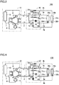
Fig. 1 shows a refrigeration cycle apparatus according to a first embodiment. -
Fig. 2 shows a refrigerant circuit when the refrigeration cycle apparatus shown inFig. 1 is performing a cooling-only operation. -
Fig. 3 shows a refrigerant circuit when the refrigeration cycle apparatus shown inFig. 1 is performing a cooling-dominated operation. -
Fig. 4 shows a refrigerant circuit when the refrigeration cycle apparatus shown inFig. 1 is performing a heating-only operation. -
Fig. 5 shows a refrigerant circuit when the refrigeration cycle apparatus shown inFig. 1 is performing a heating-dominated operation. -
Fig. 6 shows a refrigeration cycle apparatus according to a second embodiment. -
Fig. 7 shows a modification of the refrigeration cycle apparatus according to the second embodiment. -
Fig. 8 shows another modification of the refrigeration cycle apparatus according to the second embodiment. -
Fig. 9 shows a refrigerant circuit when a refrigeration cycle apparatus according to a third embodiment is performing the cooling-dominated operation. -
Fig. 10 shows a refrigerant circuit when a refrigeration cycle apparatus according to a fourth embodiment is performing the cooling-dominated operation. -
Fig. 11 shows a refrigerant circuit when a refrigeration cycle apparatus according to a fifth embodiment is performing the cooling-dominated operation. -
Fig. 12 shows a refrigerant circuit when the refrigeration cycle apparatus according to the fifth embodiment is performing the heating-dominated operation. - Embodiments of the present invention will be described in detail hereinafter with reference to the drawings, in which the same or corresponding portions are designated by the same reference characters and description thereof will not be repeated in principle.
- As shown in
Fig. 1 , arefrigeration cycle apparatus 100 according to a first embodiment includes a refrigerant circuit in which refrigerant circulates. The refrigerant circuit includes acompressor 11, a six-way valve 12, a firstoutdoor heat exchanger 13 as a first heat exchanger, a firstindoor heat exchanger 21a as a second heat exchanger, a secondindoor heat exchanger 21b as a third heat exchanger, a firstdecompressing unit 22a, a seconddecompressing unit 22b, a plurality of on-off valves decompressing unit 41, and a fourthdecompressing unit 42. The refrigerant is not particularly limited. - From a different perspective,
refrigeration cycle apparatus 100 includes anoutdoor unit 10, a firstindoor unit 20a, a secondindoor unit 20b, and abranch unit 30. A first circuit portion of the above-described refrigerantcircuit including compressor 11, six-way valve 12 and firstoutdoor heat exchanger 13 is disposed inoutdoor unit 10. A second circuit portion of the above-described refrigerant circuit including firstindoor heat exchanger 21a and firstdecompressing unit 22a is disposed in firstindoor unit 20a. A third circuit portion of the above-described refrigerant circuit including secondindoor heat exchanger 21b and seconddecompressing unit 22b is disposed in secondindoor unit 20b. A fourth circuit portion of the above-described refrigerant circuit including the plurality of on-offvalves decompressing unit 41 and fourthdecompressing unit 42 is disposed inbranch unit 30. - The above-described first circuit portion of the above-described refrigerant circuit disposed in
outdoor unit 10 and the above-described fourth circuit portion of the above-described refrigerant circuit disposed inbranch unit 30 are connected via afirst pipe 1 and asecond pipe 2. The above-described fourth circuit portion of the above-described refrigerant circuit disposed inbranch unit 30 and the above-described second circuit portion of the above-described refrigerant circuit disposed in firstindoor unit 20a are connected via athird pipe 3a and afourth pipe 4a. The above-described fourth circuit portion of the above-described refrigerant circuit disposed inbranch unit 30 and the above-described third circuit portion of the above-described refrigerant circuit disposed in secondindoor unit 20b are connected via afifth pipe 3b and asixth pipe 4b. The above-described second circuit portion and the above-described third circuit portion of the above-described refrigerant circuit are connected in parallel with the above-described fourth circuit portion. -
Compressor 11 has a discharge port through which the refrigerant is discharged, and a suction port through which the refrigerant is sucked. The discharge port ofcompressor 11 is connected to adischarge pipe 5. The suction port ofcompressor 11 is connected to asuction pipe 6.Compressor 11 is implemented by, for example, an inverter compressor in which inverter control of the number of rotations is performed. - First
outdoor heat exchanger 13 has afirst flow port 13a and asecond flow port 13b through which the refrigerant flows in and out. First flowport 13a is connected to afirst flow pipe 7, andsecond flow port 13b is connected to asecond flow pipe 8. - Six-
way valve 12 switches between a first state in which firstoutdoor heat exchanger 13 acts as a condenser and at least firstindoor heat exchanger 21a acts as an evaporator and a second state in which firstoutdoor heat exchanger 13 acts as an evaporator and at least firstindoor heat exchanger 21a acts as a condenser. - Six-
way valve 12 has a first opening P1, a second opening P2, a third opening P3, a fourth opening P4, a fifth opening P5, and a sixth opening P6. First opening P1 is connected to the discharge port ofcompressor 11 viadischarge pipe 5. Second opening P2 is connected tosecond pipe 2. Third opening P3 is connected tosecond flow port 13b of firstoutdoor heat exchanger 13 viasecond flow pipe 8. Fourth opening P4 is connected tofirst pipe 1. Fifth opening P5 is connected to the suction port ofcompressor 11 viasuction pipe 6. Sixth opening P6 is connected tofirst flow port 13a of firstoutdoor heat exchanger 13 viafirst flow pipe 7. - In the first state, a first flow path connecting the discharge port of
compressor 11 tofirst flow port 13a of firstoutdoor heat exchanger 13, a second flow path connectingsecond flow port 13b of firstoutdoor heat exchanger 13 tosecond pipe 2, and a third flow path connectingfirst pipe 1 to the suction port ofcompressor 11 are disposed in six-way valve 12. - In the second state, a fourth flow path connecting the discharge port of
compressor 11 tosecond pipe 2, a fifth flow path connectingfirst pipe 1 tosecond flow port 13b of firstoutdoor heat exchanger 13, and a sixth flow path connectingfirst flow port 13a of firstoutdoor heat exchanger 13 to the suction port ofcompressor 11 are disposed in six-way valve 12. - First
indoor heat exchanger 21a is connected in series tofirst decompressing unit 22a. Firstindoor heat exchanger 21a has two flow ports through which the refrigerant flows in and out. One flow port of firstindoor heat exchanger 21a is connected tothird pipe 3a. The other flow port of firstindoor heat exchanger 21a is connected tofourth pipe 4a via first decompressingunit 22a. - Second
indoor heat exchanger 21b is connected in series tosecond decompressing unit 22b. Secondindoor heat exchanger 21b has two flow ports through which the refrigerant flows in and out. One flow port of secondindoor heat exchanger 21b is connected tofifth pipe 3b. The other flow port of secondindoor heat exchanger 21b is connected tosixth pipe 4b viasecond decompressing unit 22b. - The above-described fourth circuit portion of the above-described refrigerant circuit disposed in
branch unit 30 further has a first connection pipe that connectsthird pipe 3a andfifth pipe 3b in parallel withfirst pipe 1, a second connection pipe that connectsthird pipe 3a andfifth pipe 3b in parallel withsecond pipe 2, a third connection pipe that connectsfourth pipe 4a andsixth pipe 4b in parallel withfirst pipe 1, and a fourth connection pipe that connectsfourth pipe 4a andsixth pipe 4b in parallel withsecond pipe 2. - The third connection pipe is a pipe that branches off from the first connection pipe. The first connection pipe and the third connection pipe have a first branch portion VI, and share a portion located on the
first pipe 1 side relative to first branch portion V1. The fourth connection pipe is a pipe that branches off from the second connection pipe. The second connection pipe and the fourth connection pipe have a second branch portion V2, and share a portion located on thesecond pipe 2 side relative to second branch portion V2. - On-off
valve 31a is disposed on thethird pipe 3a side relative to a third branch portion V3 included in the above-described first connection pipe. On-offvalve 31a is disposed betweenfirst pipe 1 andthird pipe 3a. On-offvalve 31a opens and closes a pipe of the above-described first connection pipe that connectsfirst pipe 1 andthird pipe 3a. - On-off
valve 31b is disposed on thefifth pipe 3b side relative to third branch portion V3 included in the above-described first connection pipe. On-offvalve 31b is disposed betweenfirst pipe 1 andfifth pipe 3b. On-offvalve 31b opens and closes a pipe of the above-described first connection pipe that connectsfirst pipe 1 andfifth pipe 3b. - On-off
valve 32a is disposed on thethird pipe 3a side relative to a fourth branch portion V4 included in the above-described second connection pipe. On-offvalve 32a is disposed betweensecond pipe 2 andthird pipe 3a. On-offvalve 32a opens and closes a pipe of the above-described second connection pipe that connectssecond pipe 2 andthird pipe 3a. - On-off
valve 32b is disposed on thefifth pipe 3b side relative to fourth branch portion V4 included in the above-described second connection pipe. On-offvalve 32b is disposed betweensecond pipe 2 andfifth pipe 3b. On-offvalve 32b opens and closes a pipe of the above-described second connection pipe that connectssecond pipe 2 andfifth pipe 3b. The plurality of on-offvalves - Third decompressing
unit 41 is disposed on thefirst pipe 1 side relative to a fifth branch portion V5 included in the above-described third connection pipe. Third decompressingunit 41 is disposed betweenfirst pipe 1 andfourth pipe 4a and betweenfirst pipe 1 andsixth pipe 4b. Third decompressingunit 41 opens and closes the above-described third connection pipe. - Fourth decompressing
unit 42 is disposed on thesecond pipe 2 side relative to a sixth branch portion V6 included in the above-described fourth connection pipe. Fourth decompressingunit 42 is disposed betweensecond pipe 2 andfourth pipe 4a and betweensecond pipe 2 andsixth pipe 4b. Fourth decompressingunit 42 opens and closes the above-described fourth connection pipe. - Second branch portion V2 of the above-described second connection pipe and the above-described fourth connection pipe is implemented by a
branch pipe 33.Branch pipe 33 has a flow port connected tosecond pipe 2, a flow port included in the second connection pipe, and a flow port included in the fourth connection pipe. Inbranch pipe 33, the flow port included in the second connection pipe is disposed above the flow port included in the fourth connection pipe. - As described above, six-
way valve 12 switches between the above-described first state and the above-described second state. Furthermore, whenrefrigeration cycle apparatus 100 is in the above-described first state,branch unit 30 switches between a third state shown inFig. 2 and a fourth state shown inFig. 3 . Furthermore, whenrefrigeration cycle apparatus 100 is in the above-described second state,branch unit 30 switches between a fifth state shown inFig. 4 and a sixth state shown inFig. 5 . - As shown in
Fig. 2 , in the above-described third state, all of the indoor units perform a cooling operation. That is, the above-described third state is implemented during a cooling-only operation. As shown inFig. 3 , in the above-described fourth state, firstindoor unit 20a performs the cooling operation and secondindoor unit 20b performs a heating operation, and a cooling air-conditioning load is larger than a heating air-conditioning load. That is, the above-described fourth state is implemented during a cooling-dominated operation. In other words, the above-described first state is implemented by six-way valve 12 whenrefrigeration cycle apparatus 100 performs the cooling-only operation and the cooling-dominated operation. - As shown in
Fig. 4 , in the above-described fifth state, all of the indoor units perform the heating operation. That is, the above-described fifth state is implemented during a heating-only operation. As shown inFig. 5 , in the above-described sixth state, firstindoor unit 20a performs the cooling operation and secondindoor unit 20b performs the heating operation, and the heating air-conditioning load is larger than the cooling air-conditioning load. That is, the above-described sixth state is implemented during a heating-dominated operation. In other words, the above-described second state is implemented by six-way valve 12 whenrefrigeration cycle apparatus 100 performs the heating-only operation and the heating-dominated operation. - As shown in
Fig. 2 , during the cooling-only operation, the above-described first state is implemented by six-way valve 12 and the above-described third state is implemented bybranch unit 30. During the cooling-only operation, on-offvalves branch unit 30 and fourth decompressingunit 42 are opened and on-offvalves branch unit 30 andthird decompressing unit 41 are closed. As a result, whenrefrigeration cycle apparatus 100 is in the above-described third state, a refrigerant flow path described below is formed in the above-described refrigerant circuit. - The gas single-phase refrigerant discharged from
compressor 11 flows throughdischarge pipe 5, the above-described first flow path of six-way valve 12, andfirst flow pipe 7, and flows into firstoutdoor heat exchanger 13 throughfirst flow port 13a. The gas single-phase refrigerant flowing into firstoutdoor heat exchanger 13 is subjected to heat exchange with the outdoor air, to thereby condense to liquid single-phase refrigerant. The liquid single-phase refrigerant flowing out throughsecond flow port 13b of firstoutdoor heat exchanger 13 flows through the above-described second flow path of six-way valve 12 andsecond pipe 2 intobranch unit 30. - The liquid single-phase refrigerant flowing into
branch unit 30 flows throughfourth decompressing unit 42, and then, is divided in sixth branch portion V6 into a part of the liquid single-phase refrigerant to be supplied to firstindoor unit 20a and a remaining part to be supplied to secondindoor unit 20b. The part of the liquid single-phase refrigerant flows throughfourth pipe 4a into firstindoor unit 20a and is decompressed and expanded to gas-liquid two-phase refrigerant infirst decompressing unit 22a. The remaining part of the liquid single-phase refrigerant flows throughsixth pipe 4b intosecond decompressing unit 22b and is decompressed and expanded to gas-liquid two-phase refrigerant insecond decompressing unit 22b. - The gas-liquid two-phase refrigerant flowing into each of first
indoor heat exchanger 21a and secondindoor heat exchanger 21b is subjected to heat exchange with the indoor air, to thereby evaporate to gas single-phase refrigerant. The gas single-phase refrigerant flowing out of firstindoor heat exchanger 21a flows throughthird pipe 3a and on-offvalve 31a to third branch portion V3. The gas single-phase refrigerant flowing out of secondindoor heat exchanger 21b flows throughfifth pipe 3b and on-offvalve 31b to third branch portion V3. The gas single-phase refrigerant flowing out of firstindoor heat exchanger 21a and the gas single-phase refrigerant flowing out of secondindoor heat exchanger 21b join in third branch portion V3 and flow throughfirst pipe 1 intooutdoor unit 10. A pressure of the gas single-phase refrigerant flowing throughfirst pipe 1 is lower than a pressure of the liquid single-phase refrigerant flowing throughsecond pipe 2. - The gas single-phase refrigerant flowing into
outdoor unit 10 flows through the above-described third flow path of six-way valve 12 andsuction pipe 6 and is sucked into the suction port ofcompressor 11. The gas single-phase refrigerant is compressed bycompressor 11, and then, is again discharged from the discharge port. - As shown in
Fig. 3 , during the cooling-dominated operation, the above-described first state is implemented by six-way valve 12 and the above-described fourth state is implemented bybranch unit 30. During the cooling-dominated operation, on-offvalves branch unit 30 are opened and on-offvalves branch unit 30 andthird decompressing unit 41 are closed. A degree of opening offourth decompressing unit 42 is adjusted as appropriate in accordance with a difference between the cooling air-conditioning load and the heating air-conditioning load. As a result, whenrefrigeration cycle apparatus 100 is in the above-described fourth state, a refrigerant flow path described below is formed in the above-described refrigerant circuit. - The gas single-phase refrigerant discharged from
compressor 11 flows throughdischarge pipe 5, the above-described first flow path of six-way valve 12, andfirst flow pipe 7, and flows into firstoutdoor heat exchanger 13 throughfirst flow port 13a. The gas single-phase refrigerant flowing into firstoutdoor heat exchanger 13 is subjected to heat exchange with the outdoor air, to thereby condense to gas-liquid two-phase refrigerant. The gas-liquid two-phase refrigerant flowing out throughsecond flow port 13b of firstoutdoor heat exchanger 13 flows through the above-described second flow path of six-way valve 12 andsecond pipe 2 intobranch unit 30. - The gas-liquid two-phase refrigerant flowing into
branch unit 30 is divided bybranch pipe 33 disposed in second branch portion V2 into gas single-phase refrigerant flowing through the above-described second connection pipe and liquid single-phase refrigerant flowing through the above-described fourth connection pipe. This is because the flow port ofbranch pipe 33 included in the second connection pipe is disposed above the flow port ofbranch pipe 33 included in the fourth connection pipe as described above. - The gas single-phase refrigerant subjected to gas-liquid separation by
branch pipe 33 flows through on-offvalve 32b disposed in the above-described second connection pipe andfifth pipe 3b into secondindoor heat exchanger 21b and is subjected to heat exchange with the indoor air, to thereby condense to liquid single-phase refrigerant. The liquid single-phase refrigerant flows throughsecond decompressing unit 22b andsixth pipe 4b intobranch unit 30 and reaches sixth branch portion V6. The liquid single-phase refrigerant subjected to gas-liquid separation bybranch pipe 33 flows throughfourth decompressing unit 42 disposed in the above-described fourth connection pipe to sixth branch portion V6, where the liquid single-phase refrigerant subjected to gas-liquid separation bybranch pipe 33 joins with the liquid single-phase refrigerant flowing throughsixth pipe 4b into sixth branch portion V6. The liquid single-phase refrigerant flows throughfourth pipe 4a into first decompressingunit 22a and is decompressed and expanded to gas-liquid two-phase refrigerant infirst decompressing unit 22a. The gas-liquid two-phase refrigerant flowing into firstindoor heat exchanger 21a is subjected to heat exchange with the indoor air, to thereby evaporate to gas single-phase refrigerant. - The gas single-phase refrigerant flowing out of first
indoor heat exchanger 21a flows throughthird pipe 3a, on-offvalve 31a andfirst pipe 1 intooutdoor unit 10. A pressure of the gas single-phase refrigerant flowing throughfirst pipe 1 is lower than a pressure of the gas-liquid two-phase refrigerant flowing throughsecond pipe 2. - The gas single-phase refrigerant flowing into
outdoor unit 10 flows through the above-described third flow path of six-way valve 12 andsuction pipe 6 and is sucked into the suction port ofcompressor 11. The gas single-phase refrigerant is compressed bycompressor 11, and then, is again discharged from the discharge port. - As shown in
Fig. 4 , during the heating-only operation, the above-described second state is implemented by six-way valve 12 and the above-described fifth state is implemented bybranch unit 30. During the heating-only operation, on-offvalves branch unit 30 andthird decompressing unit 41 are opened and on-offvalves branch unit 30 and fourth decompressingunit 42 are closed. As a result, whenrefrigeration cycle apparatus 100 is in the above-described fifth state, a refrigerant flow path described below is formed in the above-described refrigerant circuit. - The gas single-phase refrigerant discharged from
compressor 11 flows throughdischarge pipe 5, the above-described fourth flow path of six-way valve 12, andsecond pipe 2 intobranch unit 30. The gas single-phase refrigerant flowing intobranch unit 30 flows through the above-described second connection pipe, and then, is divided in the fourth branch portion into a part of the gas single-phase refrigerant to be supplied to firstindoor unit 20a and a remaining part to be supplied to secondindoor unit 20b. The part of the gas single-phase refrigerant flows through on-offvalve 32a andthird pipe 3a into firstindoor heat exchanger 21a. The remaining part of the gas single-phase refrigerant flows through on-offvalve 32b andfifth pipe 3b into secondindoor heat exchanger 21b. - The gas single-phase refrigerant flowing into each of first
indoor heat exchanger 21a and secondindoor heat exchanger 21b is subjected to heat exchange with the indoor air, to thereby condense to liquid single-phase refrigerant. The liquid single-phase refrigerant is decompressed and expanded to gas-liquid two-phase refrigerant infirst decompressing unit 22a orsecond decompressing unit 22b. - The gas-liquid two-phase refrigerant flowing out of first
indoor unit 20a flows throughfourth pipe 4a to fifth branch portion V5. The gas-liquid two-phase refrigerant flowing out of secondindoor unit 20b flows throughsixth pipe 4b to fifth branch portion V5. The gas-liquid two-phase refrigerant flowing out of firstindoor unit 20a and the gas-liquid two-phase refrigerant flowing out of secondindoor unit 20b join in fifth branch portion V5 and flow throughthird decompressing unit 41 andfirst pipe 1 intooutdoor unit 10. A pressure of the gas-liquid two-phase refrigerant flowing throughfirst pipe 1 is lower than a pressure of the gas single-phase refrigerant flowing throughsecond pipe 2. - The gas-liquid two-phase refrigerant flowing into
outdoor unit 10 flows through the above-described fifth flow path of six-way valve 12 andsecond flow pipe 8, and flows into firstoutdoor heat exchanger 13 throughsecond flow port 13b. The gas-liquid two-phase refrigerant flowing into firstoutdoor heat exchanger 13 is subjected to heat exchange with the outdoor air, to thereby evaporate to gas single-phase refrigerant. The gas single-phase refrigerant flowing out throughfirst flow port 13a of firstoutdoor heat exchanger 13 flows through the above-described sixth flow path of six-way valve 12 andsuction pipe 6 and is sucked into the suction port ofcompressor 11. The gas single-phase refrigerant is compressed bycompressor 11, and then, is again discharged from the discharge port. - As shown in
Fig. 5 , during the heating-dominated operation, the above-described second state is implemented by six-way valve 12 and the above-described sixth state is implemented bybranch unit 30. During the heating-dominated operation, on-offvalves branch unit 30 are opened and on-offvalves branch unit 30 and fourth decompressingunit 42 are closed. A degree of opening ofthird decompressing unit 41 is adjusted as appropriate in accordance with a difference between the cooling air-conditioning load and the heating air-conditioning load. As a result, whenrefrigeration cycle apparatus 100 is in the above-described sixth state, a refrigerant flow path described below is formed in the above-described refrigerant circuit. - The gas single-phase refrigerant discharged from
compressor 11 flows throughdischarge pipe 5, the above-described fourth flow path of six-way valve 12, andsecond pipe 2 intobranch unit 30. The gas single-phase refrigerant flowing intobranch unit 30 flows through on-offvalve 32b disposed in the above-described second connection pipe andfifth pipe 3b into secondindoor heat exchanger 21b and is subjected to heat exchange with the indoor air, to thereby condense to liquid single-phase refrigerant. The liquid single-phase refrigerant flows throughsecond decompressing unit 22b andsixth pipe 4b intobranch unit 30 and reaches fifth branch portion V5. - A part of the liquid single-phase refrigerant reaching fifth branch portion V5 flows into
third decompressing unit 41 and is decompressed and expanded to gas-liquid two-phase refrigerant inthird decompressing unit 41. - A remaining part of the liquid single-phase refrigerant reaching fifth branch portion V5 flows through
fourth pipe 4a into first decompressingunit 22a and is decompressed and expanded to gas-liquid two-phase refrigerant infirst decompressing unit 22a. The gas-liquid two-phase refrigerant flowing into firstindoor heat exchanger 21a is subjected to heat exchange with the indoor air, to thereby evaporate to gas single-phase refrigerant. The gas single-phase refrigerant flows throughthird pipe 3a and on-offvalve 31a to first branch portion VI, and joins with the gas-liquid two-phase refrigerant flowing throughthird decompressing unit 41 into first branch portion V1. The gas-liquid two-phase refrigerant flows throughfirst pipe 1 intooutdoor unit 10. A pressure of the gas-liquid two-phase refrigerant flowing throughfirst pipe 1 is lower than a pressure of the gas single-phase refrigerant flowing throughsecond pipe 2. - The gas-liquid two-phase refrigerant flowing into
outdoor unit 10 flows through the above-described fifth flow path of six-way valve 12 andsecond flow pipe 8, and flows into firstoutdoor heat exchanger 13 throughsecond flow port 13b. The gas-liquid two-phase refrigerant flowing into firstoutdoor heat exchanger 13 is subjected to heat exchange with the outdoor air, to thereby evaporate to gas single-phase refrigerant. The gas single-phase refrigerant flowing out throughfirst flow port 13a of firstoutdoor heat exchanger 13 flows through the above-described sixth flow path of six-way valve 12 andsuction pipe 6 and is sucked into the suction port ofcompressor 11. The gas single-phase refrigerant is compressed bycompressor 11, and then, is again discharged from the discharge port. -
Refrigeration cycle apparatus 100 is a refrigeration cycle apparatus having a refrigerant circuit in which refrigerant circulates.Refrigeration cycle apparatus 100 includes:outdoor unit 10;branch unit 30 connected tooutdoor unit 10 via the first pipe and the second pipe; firstindoor unit 20a connected to branchunit 30 via the third pipe and the fourth pipe; and secondindoor unit 20b connected to branchunit 30 via the fifth pipe and the sixth pipe. The refrigerant circuit includescompressor 11, firstoutdoor heat exchanger 13, firstindoor heat exchanger 21a, secondindoor heat exchanger 21b, and six-way valve 12.Compressor 11, firstoutdoor heat exchanger 13 and six-way valve 12 are located inoutdoor unit 10. Firstindoor heat exchanger 21a is disposed in firstindoor unit 20a. Secondindoor heat exchanger 21b is disposed in secondindoor unit 20b. Firstoutdoor heat exchanger 13 has a first flow port and a second flow port through which the refrigerant flows in and out in the refrigerant circuit - Six-
way valve 12 switches between the first state in which firstoutdoor heat exchanger 13 acts as a condenser and at least the second heat exchanger acts as an evaporator and the second state in which firstoutdoor heat exchanger 13 acts as an evaporator and at least the second heat exchanger acts as a condenser. In the first state, the first flow path connecting the discharge port ofcompressor 11 to the first flow port of firstoutdoor heat exchanger 13, the second flow path connecting the second flow port of firstoutdoor heat exchanger 13 to the second pipe, and the third flow path connecting the first pipe to the suction port ofcompressor 11 are disposed in six-way valve 12. In the second state, the fourth flow path connecting the discharge port ofcompressor 11 to the second pipe, the fifth flow path connecting the first pipe to the second flow port of firstoutdoor heat exchanger 13, and the sixth flow path connecting the first flow port of firstoutdoor heat exchanger 13 to the suction port ofcompressor 11 are disposed in six-way valve 12. - In the first state,
branch unit 30 switches between the third state in which firstindoor heat exchanger 21a and secondindoor heat exchanger 21b act as evaporators and the fourth state in which firstindoor heat exchanger 21a acts as an evaporator and secondindoor heat exchanger 21b acts as a condenser. In the second state,branch unit 30 switches between the fifth state in which firstindoor heat exchanger 21a and secondindoor heat exchanger 21b act as condensers and the sixth state in which secondindoor heat exchanger 21b acts as a condenser and firstindoor heat exchanger 21a acts as an evaporator. - In such
refrigeration cycle apparatus 100, by one six-way valve 12 and onebranch unit 30, switching can be performed among the cooling-only operation, the cooling-dominated operation, the heating-only operation, and the heating-dominated operation. For example, as for an air-conditioning facility in a large building, when an operation state of an indoor unit disposed in a general room is heating, an operation state of an indoor unit disposed in a room having a large amount of heat generation, such as a computer room or a kitchen, may in some cases be cooling.Refrigeration cycle apparatus 100 described above is suitable for such an air-conditioning facility. - Furthermore, in
refrigeration cycle apparatus 100, in all of the above-described operation states, the pressure of the gas-liquid two-phase refrigerant flowing throughfirst pipe 1 is lower than the pressure of the gas single-phase refrigerant flowing throughsecond pipe 2. In contrast, in the refrigeration cycle apparatus described inPTL 1 above, the above-described switching is implemented by one four-way valve, four check valves and one branch unit. - That is, the number of components for performing the above-described switching is smaller in
refrigeration cycle apparatus 100 than in the refrigeration cycle apparatus described inPTL 1 above. As a result, the manufacturing cost ofrefrigeration cycle apparatus 100 can be reduced as compared with the manufacturing cost of the above-described conventional refrigeration cycle apparatus. The manufacturing cost ofrefrigeration cycle apparatus 100 is also reduced as compared with the manufacturing cost when the four check valves are replaced with four solenoid valves in the above-described conventional refrigeration cycle apparatus. - In addition, in the above-described conventional refrigeration cycle apparatus, the refrigerant flows through two of the check valves and two flow paths in the four-way valve in any of the operation states. A pressure loss of the refrigerant flowing through a check valve is higher than a pressure loss of the refrigerant flowing through one flow path in the four-way valve or six-
way valve 12. Particularly when a diameter of the check valve is set relatively small in order to reduce the manufacturing cost thereof, the pressure loss of the refrigerant flowing through the check valve is significantly higher than the pressure loss of the refrigerant flowing through one flow path in the four-way valve or six-way valve 12. On the other hand, when the diameter of the check valve is increased in order to reduce the pressure loss of the refrigerant flowing through the check valve, the manufacturing cost of the refrigeration cycle apparatus is increased. - In contrast, in
refrigeration cycle apparatus 100, the refrigerant flows through three flow paths in six-way valve 12 in any of the operation states. A sum of pressure losses of the refrigerant flowing through three flow paths in six-way valve 12 may be smaller than a sum of pressure losses of the refrigerant flowing through two of the check valves and two flow paths in the four-way valve. That is, inrefrigeration cycle apparatus 100, the manufacturing cost is reduced and the pressure loss is also reduced, as compared with the above-described conventional refrigeration cycle apparatus. - Particularly, in the above-described conventional refrigeration cycle apparatus, the gas single-phase refrigerant flowing out of the indoor heat exchanger that acts as an evaporator during the cooling-only operation and during the cooling-dominated operation flows through one check valve and one flow path in the four-way valve. In contrast, in
refrigeration cycle apparatus 100, the gas single-phase refrigerant flowing out of the indoor heat exchanger that acts as an evaporator during the cooling-only operation and during the cooling-dominated operation flows through the third flow path of six-way valve 12 to the suction port ofcompressor 11. Therefore, a suction pressure loss during the cooling-only operation and during the cooling-dominated operation is lower inrefrigeration cycle apparatus 100 than in the above-described conventional refrigeration cycle apparatus. - In addition, the number of components is smaller, and thus, the number of connections between the components is smaller and the number of brazed portions on the above-described refrigerant circuit is also smaller in
refrigeration cycle apparatus 100 than in the above-described conventional refrigeration cycle apparatus. As a result, the risk of the occurrence of poor connection between the brazed portions inrefrigeration cycle apparatus 100 is lower than the risk of the occurrence of poor connection between the brazed portions in the above-described conventional refrigeration cycle apparatus. Furthermore,outdoor unit 10 ofrefrigeration cycle apparatus 100 can be reduced in size because the number of components is smaller inoutdoor unit 10 ofrefrigeration cycle apparatus 100 than in the outdoor unit of the above-described conventional refrigeration cycle apparatus. - Particularly, the above-described check valves have limitations in terms of arrangement, whereas six-
way valve 12 does not have such limitations. Therefore, the refrigerant pipes connected to six-way valve 12 inrefrigeration cycle apparatus 100 can be made shorter than the refrigerant pipes connected to four check valves in the above-described conventional refrigeration cycle apparatus. As a result,outdoor unit 10 ofrefrigeration cycle apparatus 100 can be reduced in size, as compared with the outdoor unit of the above-described conventional refrigeration cycle apparatus. - In addition, the upward force caused by a refrigerant flow and the downward force caused by the gravity force or the elastic force of a spring are applied to a valve body of a general check valve as described above. Opening and closing of the check valve is switched in accordance with whether or not one of the two forces is greater than the other. In addition, in the case of an inverter compressor, the number of rotations of the compressor is controlled in accordance with an air-conditioning load. Therefore, when an air-conditioning load of a refrigeration cycle apparatus is small, the number of rotations of the compressor is small and a flow rate of the refrigerant decreases. Thus, in the case where the above-described conventional refrigeration cycle apparatus includes the above-described general check valve and the above-described inverter compressor, the upward force applied to the valve body of the check valve may be reduced to thereby balance with the downward force applied to the valve body, when the air-conditioning load is small. In this case, the valve body vibrates without being fixed, and periodically comes into collision with another member such as a valve chamber of the check valve. As a result, the valve body or the other member of the check valve may be scraped to thereby reduce a closing capacity of the check valve, and/or noise may occur. In contrast, switching between the above-described first state and the above-described second state by six-
way valve 12 is not performed by the force applied to a valve body due to a refrigerant flow. Therefore, an abnormality that occurs in the above-described check valve does not occur in six-way valve 12, even when the air-conditioning load is small and the flow rate of the refrigerant decreases. Thus, inrefrigeration cycle apparatus 100, the above-described occurrence of the abnormality is reduced or prevented even whencompressor 11 is an inverter compressor, and thus,refrigeration cycle apparatus 100 is particularly suitable for a refrigeration cycle apparatus including an inverter compressor. - In addition, a plurality of branch pipes are disposed in the outdoor unit of the above-described conventional refrigeration cycle apparatus. For example, a branch pipe for connecting the four-way valve and the outdoor heat exchanger in parallel is disposed in the outdoor unit for each of two connection pipes that connect the outdoor unit and the branch unit to the outdoor heat exchanger. The branch pipe is provided to switch between a flow path through which the refrigerant flows during the cooling-only operation and during the cooling-dominated operation and a flow path through which the refrigerant flows during the heating-only operation and during the heating-dominated operation, and one check valve is disposed in each flow path. The gas single-phase refrigerant evaporated in the indoor heat exchanger during the heating-only operation and during the heating-dominated operation flows through one connection pipe into the outdoor unit, and flows through one of the two flow paths that branch off by the above-described branch pipe, and reaches the suction port of the compressor. A pressure loss also occurs when the gas single-phase refrigerant flows through the above-described branch pipe. In contrast, in
refrigeration cycle apparatus 100, six-way valve 12 switches between the above-described first state and the above-described second state, and thus, the branch pipes and the check valves for performing the switching are unnecessary. As a result, inrefrigeration cycle apparatus 100, a reduction in manufacturing cost and a reduction in pressure loss are simultaneously achieved, as compared with the above-described conventional refrigeration cycle apparatus. - As described above, in
refrigeration cycle apparatus 100, a reduction in manufacturing cost, a reduction in pressure loss, a reduction in risk of the occurrence of poor connection between the brazed portions, and a reduction in size ofoutdoor unit 10 are simultaneously achieved, as compared with the above-described conventional refrigeration cycle apparatus. Furthermore,refrigeration cycle apparatus 100 is particularly suitable for a refrigeration cycle apparatus including an inverter compressor. - As shown in
Fig. 6 , arefrigeration cycle apparatus 101 according to a second embodiment is configured basically similarly torefrigeration cycle apparatus 100 according to the first embodiment. However,refrigeration cycle apparatus 101 according to the second embodiment is different fromrefrigeration cycle apparatus 100 according to the first embodiment in thatrefrigeration cycle apparatus 101 according to the second embodiment includes a refrigerant circuit in which refrigerant circulates and a heat medium circuit in which a heat medium circulates. - The refrigerant circuit includes
compressor 11, six-way valve 12, firstoutdoor heat exchanger 13, a first branchunit heat exchanger 52a as a second heat exchanger, a second branchunit heat exchanger 52b as a third heat exchanger, a plurality of on-offvalves fifth decompressing unit 53a, asixth decompressing unit 53b, aseventh decompressing unit 56, and aneighth decompressing unit 57. - The heat medium circuit includes a
first pump 51a, asecond pump 51b, first branchunit heat exchanger 52a, second branchunit heat exchanger 52b, a plurality of on-offvalves indoor heat exchanger 21a, secondindoor heat exchanger 21b, a first flowrate control unit 23a, and a second flowrate control unit 23b. - The refrigerant is not particularly limited and may be, for example, fluorocarbon refrigerant suitable for a vapor compression-type refrigeration cycle.
- The heat medium is, for example, water or an antifreezing solution (such as, for example, propylene glycol or ethylene glycol).
-
Refrigeration cycle apparatus 101 includesoutdoor unit 10, firstindoor unit 20a, secondindoor unit 20b, and abranch unit 50. - A first circuit portion of the above-described refrigerant
circuit including compressor 11, six-way valve 12 and firstoutdoor heat exchanger 13 is disposed inoutdoor unit 10. A fifth circuit portion of the above-described refrigerant circuit including first branchunit heat exchanger 52a, second branchunit heat exchanger 52b, the plurality of on-offvalves fifth decompressing unit 53a,sixth decompressing unit 53b, seventh decompressingunit 56, andeighth decompressing unit 57 is disposed inbranch unit 50. - Furthermore, a first circuit portion of the heat medium circuit including
first pump 51a,second pump 51b, first branchunit heat exchanger 52a, second branchunit heat exchanger 52b, and the plurality of on-offvalves branch unit 50. A second circuit portion of the above-described heat medium circuit including firstindoor heat exchanger 21a and first flowrate control unit 23a is disposed in firstindoor unit 20a. A third circuit portion of the above-described heat medium circuit including secondindoor heat exchanger 21b and second flowrate control unit 23b is disposed in secondindoor unit 20b. - The above-described first circuit portion of the above-described refrigerant circuit disposed in
outdoor unit 10 and the above-described fifth circuit portion of the above-described refrigerant circuit disposed inbranch unit 50 are connected viafirst pipe 1 andsecond pipe 2. The above-described first circuit portion of the above-described heat medium circuit disposed inbranch unit 50 and the above-described second circuit portion of the above-described heat medium circuit disposed in firstindoor unit 20a are connected viathird pipe 3a andfourth pipe 4a. The above-described first circuit portion of the above-described heat medium circuit disposed inbranch unit 50 and the above-described third circuit portion of the above-described heat medium circuit disposed in secondindoor unit 20b are connected viafifth pipe 3b andsixth pipe 4b. The second circuit portion and the third circuit portion of the above-described heat medium circuit are connected in parallel with the first circuit portion of the above-described heat medium circuit. -
Outdoor unit 10 ofrefrigeration cycle apparatus 101 is configured similarly tooutdoor unit 10 ofrefrigeration cycle apparatus 100. That is, six-way valve 12 ofrefrigeration cycle apparatus 101 is configured similarly to six-way valve 12 ofrefrigeration cycle apparatus 100 and can switch between the above-described first state and the above-described second state. - The fifth circuit portion of the above-described refrigerant circuit disposed in
branch unit 50 further includes abranch pipe 58 configured similarly tobranch pipe 33 inrefrigeration cycle apparatus 100.Branch pipe 58 has a flow port connected tosecond pipe 2, a flow port disposed above the above-described flow port, and a flow port disposed below the above-described flow port. - An eleventh pipe connected to
first pipe 1, a twelfth pipe connected to the flow port ofbranch pipe 58 disposed in the lower part, and thirteenth, fourteenth and fifteenth pipes that connect the eleventh pipe to the twelfth pipe and are disposed in parallel are disposed in the above-described fifth circuit portion. On-offvalve 54a, first branchunit heat exchanger 52a andfifth decompressing unit 53a are included in the thirteenth pipe and disposed in this order from thefirst pipe 1 side. On-offvalve 54b, second branchunit heat exchanger 52b andsixth decompressing unit 53b are included in the fourteenth pipe and disposed in this order from thefirst pipe 1 side.Seventh decompressing unit 56 is included in the fifteenth pipe.Eighth decompressing unit 57 is included in the twelfth pipe. - A sixteenth pipe connected to the flow port of
branch pipe 58 disposed in the upper part, a seventeenth pipe that connects the sixteenth pipe to a portion of the thirteenth pipe located between on-offvalve 54a and first branchunit heat exchanger 52a, and an eighteenth pipe that connects the sixteenth pipe to a portion of the fourteenth pipe located between on-offvalve 54b and second branchunit heat exchanger 52b are further disposed in the above-described fifth circuit portion. On-offvalve 55a is included in the seventeenth pipe. On-offvalve 55b is included in the eighteenth pipe. - Twentieth and twenty-first pipes connected in parallel with the second circuit portion of the above-described heat medium circuit disposed in first
indoor unit 20a, and twenty-second and twenty-third pipes connected in parallel with the third circuit portion of the above-described heat medium circuit disposed in secondindoor unit 20b are disposed in the first circuit portion of the above-described heat medium circuit disposed inbranch unit 50. - The above-described twentieth pipe and the above-described twenty-second pipe share a part thereof, and
first pump 51a and first branchunit heat exchanger 52a are included in the part. The above-described twenty-first pipe and the above-described twenty-third pipe share a part thereof, andsecond pump 51b and second branchunit heat exchanger 52b are included in the part. On-offvalves valves valves valves - From a different perspective, first
indoor unit 20a and secondindoor unit 20b are connected in parallel with first branchunit heat exchanger 52a in the above-described heat medium circuit. Furthermore, firstindoor unit 20a and secondindoor unit 20b are connected in parallel with second branchunit heat exchanger 52b in the above-described heat medium circuit. - First branch
unit heat exchanger 52a and second branchunit heat exchanger 52b perform heat exchange between the refrigerant and the heat medium. First branchunit heat exchanger 52a is disposed on the outflow side offirst pump 51a in the above-described twentieth pipe and the above-described twenty-second pipe. Second branchunit heat exchanger 52b is disposed on the outflow side ofsecond pump 51b in the above-described twenty-first pipe and the above-described twenty-third pipe. - First flow
rate control unit 23a controls a flow rate of the heat medium supplied to firstindoor heat exchanger 21a. Second flowrate control unit 23b controls a flow rate of the heat medium supplied to secondindoor heat exchanger 21b. - As described above, six-
way valve 12 switches between the above-described first state and the above-described second state. Furthermore, whenrefrigeration cycle apparatus 101 is in the above-described first state,branch unit 50 switches between a seventh state in which first branchunit heat exchanger 52a and second branchunit heat exchanger 52b act as evaporators and an eighth state in which one of first branchunit heat exchanger 52a and second branchunit heat exchanger 52b acts as an evaporator and the other acts as a condenser. Furthermore, whenrefrigeration cycle apparatus 101 is in the above-described second state,branch unit 50 switches between a ninth state in which first branchunit heat exchanger 52a and second branchunit heat exchanger 52b act as condensers and a tenth state in which one of first branchunit heat exchanger 52a and second branchunit heat exchanger 52b acts as a condenser and the other acts as an evaporator. - The above-described seventh state is implemented during the cooling-only operation. The above-described eighth state is implemented during the cooling-dominated operation. The above-described ninth state is implemented during the heating-only operation. The above-described tenth state is implemented during the heating-dominated operation.
- Refrigerant flow paths in
outdoor unit 10 whenrefrigeration cycle apparatus 101 is in the above-described seventh state, the above-described eighth state, the above-described ninth state, and the above-described tenth state are similar to the refrigerant flow paths inoutdoor unit 10 whenrefrigeration cycle apparatus 100 is in the above-described first state, the above-described second state, the above-described third state, and the above-described fourth state, respectively. - Therefore,
refrigeration cycle apparatus 101 can provide an effect similar to that ofrefrigeration cycle apparatus 100. - Furthermore, the above-described refrigerant circuit of
refrigeration cycle apparatus 101 is disposed only inoutdoor unit 10,branch unit 50,first pipe 1, andsecond pipe 2, and is not disposed in firstindoor unit 20a and secondindoor unit 20b. Therefore, an amount of the refrigerant contained in the above-described refrigerant circuit ofrefrigeration cycle apparatus 101 can be smaller than an amount of the refrigerant contained in the above-described refrigerant circuit ofrefrigeration cycle apparatus 100. Furthermore, the risk of leakage of the refrigerant to the interior inrefrigeration cycle apparatus 101 is significantly lower than the risk of leakage of the refrigerant to the interior inrefrigeration cycle apparatus 100. - The above-described fifth circuit portion of the above-described refrigerant circuit of
refrigeration cycle apparatus 101 disposed inbranch unit 50 and the above-described heat medium circuit may be configured arbitrarily and are not limited to the above-described configuration. The above-described fifth circuit portion and the above-described heat medium circuit ofrefrigeration cycle apparatus 101 are configured similarly to those of a conventional refrigeration cycle apparatus including a refrigerant circuit and a heat medium circuit, for example. - As shown in
Figs. 7 and8 , first flowrate control unit 23a and second flowrate control unit 23b may be disposed inbranch unit 50. - As shown in
Fig. 7 , first flowrate control unit 23a may be disposed betweenfourth pipe 4a and on-offvalves rate control unit 23b may be disposed betweensixth pipe 4b and on-offvalves - As shown in
Fig. 8 , first flowrate control unit 23a may be disposed betweenthird pipe 3a and on-offvalves rate control unit 23b may be disposed betweenfifth pipe 3b and on-offvalves - As shown in
Fig. 9 , arefrigeration cycle apparatus 102 according to a third embodiment is configured basically similarly torefrigeration cycle apparatus 100 according to the first embodiment. However,refrigeration cycle apparatus 102 according to the third embodiment is different fromrefrigeration cycle apparatus 100 according to the first embodiment in thatrefrigeration cycle apparatus 102 according to the third embodiment further includes a secondoutdoor heat exchanger 14 as a fourth heat exchanger, and on-offvalves refrigeration cycle apparatus 102 is configured basically similarly to the above-described refrigerant circuit ofrefrigeration cycle apparatus 100. However, the refrigerant circuit ofrefrigeration cycle apparatus 102 is different from the above-described refrigerant circuit ofrefrigeration cycle apparatus 100 in that the refrigerant circuit ofrefrigeration cycle apparatus 102 further includes secondoutdoor heat exchanger 14 and on-offvalves Fig. 9 shows a refrigerant circuit whenrefrigeration cycle apparatus 102 is performing the cooling-dominated operation. - Second
outdoor heat exchanger 14 and on-offvalves outdoor unit 10. In the above-described refrigerant circuit, secondoutdoor heat exchanger 14 and on-offvalves outdoor heat exchanger 13 are connected in parallel betweenfirst flow pipe 7 andsecond flow pipe 8. On-offvalve 15 is disposed between secondoutdoor heat exchanger 14 andfirst flow pipe 7. On-offvalve 16 is disposed between secondoutdoor heat exchanger 14 andsecond flow pipe 8. - The operation for opening and closing on-off
valves valves - Since
refrigeration cycle apparatus 102 includes firstoutdoor heat exchanger 13 and secondoutdoor heat exchanger 14, a cooling and heating capacity when both of firstoutdoor heat exchanger 13 and secondoutdoor heat exchanger 14 act as condensers or evaporators is higher than a cooling and heating capacity of a refrigeration cycle apparatus including only one of firstoutdoor heat exchanger 13 and secondoutdoor heat exchanger 14. - Furthermore, in
refrigeration cycle apparatus 102, an operation state in which secondoutdoor heat exchanger 14 is not used is implemented by closing on-offvalves outdoor heat exchanger 13 and secondoutdoor heat exchanger 14 act as condensers when the outdoor air temperature is low during the cooling-dominated operation, a heat release capacity thereof becomes excessive, which leads to a reduction in condensation pressure. As a result, a saturation temperature of the gas-phase refrigerant supplied to the indoor heat exchangers that are performing the heating operation decreases, and thus, a requested heating capacity is not obtained. In such a case, inrefrigeration cycle apparatus 102, the heat release capacity of the condensers can be reduced by closing on-offvalves refrigeration cycle apparatus 102, the requested heating capacity can be obtained even in the above-described case. - As shown in
Fig. 10 , arefrigeration cycle apparatus 103 according to a fourth embodiment is configured basically similarly torefrigeration cycle apparatus 100 according to the first embodiment. However,refrigeration cycle apparatus 103 according to the fourth embodiment is different fromrefrigeration cycle apparatus 100 according to the first embodiment in thatrefrigeration cycle apparatus 103 according to the fourth embodiment further includes secondoutdoor heat exchanger 14 and on-offvalves refrigeration cycle apparatus 103 is configured basically similarly to the above-described refrigerant circuit ofrefrigeration cycle apparatus 100. However, the refrigerant circuit ofrefrigeration cycle apparatus 103 is different from the above-described refrigerant circuit ofrefrigeration cycle apparatus 100 in that the refrigerant circuit ofrefrigeration cycle apparatus 103 further includes secondoutdoor heat exchanger 14 and on-offvalves Fig. 10 shows a refrigerant circuit whenrefrigeration cycle apparatus 103 is performing the cooling-dominated operation and secondoutdoor heat exchanger 14 does not act as a condenser. - Second
outdoor heat exchanger 14 and on-offvalves outdoor unit 10. In the above-described refrigerant circuit, secondoutdoor heat exchanger 14 and on-offvalves outdoor heat exchanger 13 are connected in parallel betweendischarge pipe 5 andsecond flow pipe 8. On-offvalve 16 is disposed between secondoutdoor heat exchanger 14 andsecond flow pipe 8. On-offvalve 17 is disposed between secondoutdoor heat exchanger 14 anddischarge pipe 5. On-offvalve 18 is disposed between secondoutdoor heat exchanger 14 andsuction pipe 6. - In the above-described first state and the above-described second state, on-off
valve 16 is opened when firstoutdoor heat exchanger 13 and secondoutdoor heat exchanger 14 are used, and is closed when secondoutdoor heat exchanger 14 is not used. - In the above-described first state, on-off
valve 17 is opened when firstoutdoor heat exchanger 13 and secondoutdoor heat exchanger 14 are used, and is closed when secondoutdoor heat exchanger 14 is not used. In the above-described second state, on-offvalve 17 is closed. In the above-described first state, the operation for opening and closing on-offvalves valves - In the above-described first state, on-off
valve 18 is closed when firstoutdoor heat exchanger 13 and secondoutdoor heat exchanger 14 are used, and is opened when secondoutdoor heat exchanger 14 is not used. In the above-described second state, on-offvalve 18 is opened when firstoutdoor heat exchanger 13 and secondoutdoor heat exchanger 14 are used, and is closed when secondoutdoor heat exchanger 14 is not used. - Since
refrigeration cycle apparatus 103 includes firstoutdoor heat exchanger 13 and secondoutdoor heat exchanger 14, a cooling and heating capacity when both of firstoutdoor heat exchanger 13 and secondoutdoor heat exchanger 14 act as condensers or evaporators is higher than a cooling and heating capacity of a refrigeration cycle apparatus including only one of firstoutdoor heat exchanger 13 and secondoutdoor heat exchanger 14. - Furthermore, in
refrigeration cycle apparatus 103, an operation state in which secondoutdoor heat exchanger 14 is not used is implemented by closing on-offvalves Fig. 10 . Such an operation state is implemented, for example, when the outdoor air temperature is low during the cooling-dominated operation. If firstoutdoor heat exchanger 13 and secondoutdoor heat exchanger 14 act as condensers when the outdoor air temperature is low during the cooling-dominated operation, a heat release capacity thereof becomes excessive, which leads to a reduction in condensation pressure. As a result, a saturation temperature of the gas-phase refrigerant supplied to the indoor heat exchangers that are performing the heating operation decreases, and thus, a requested heating capacity is not obtained. In such a case, inrefrigeration cycle apparatus 103, the heat release capacity of the condensers can be reduced by closing on-offvalves refrigeration cycle apparatus 102, the requested heating capacity can be obtained even in the above-described case. - In addition, as shown in
Fig. 10 , on-offvalve 18 is preferably opened during an operation state in which secondoutdoor heat exchanger 14 is not used. With this, even when a closing capacity of on-offvalve 16 or on-offvalve 17 is insufficient and the refrigerant flows into secondoutdoor heat exchanger 14, the refrigerant flowing into secondoutdoor heat exchanger 14 is sucked intocompressor 11, and thus, accumulation in secondoutdoor heat exchanger 14 can be prevented. - As shown in
Figs. 11 and 12 , arefrigeration cycle apparatus 104 according to a fifth embodiment is configured basically similarly torefrigeration cycle apparatus 102 according to the third embodiment. However,refrigeration cycle apparatus 104 according to the fifth embodiment is different fromrefrigeration cycle apparatus 102 according to the third embodiment in that fourth opening P4 is connected to the suction port ofcompressor 11 viasuction pipe 6 and fifth opening P5 is connected tofirst pipe 1.Fig. 11 shows a refrigerant circuit whenrefrigeration cycle apparatus 104 is performing the cooling-dominated operation.Fig. 12 shows a refrigerant circuit whenrefrigeration cycle apparatus 104 is performing the heating-dominated operation. - As shown in
Figs. 11 and 12 , in either of the above-described first state and the above-described second state,first flow pipe 7 ofrefrigeration cycle apparatus 104 is disposed upstream of firstoutdoor heat exchanger 13 and secondoutdoor heat exchanger 14. In either of the above-described first state and the above-described second state,second flow pipe 8 ofrefrigeration cycle apparatus 104 is disposed downstream of firstoutdoor heat exchanger 13 and secondoutdoor heat exchanger 14. Therefore, inrefrigeration cycle apparatus 104, a flow direction of the refrigerant flowing through firstoutdoor heat exchanger 13 and secondoutdoor heat exchanger 14 is fixed in either of the above-described first state and the above-described second state. - As a result, in either of the above-described first state and the above-described second state, on-off
valve 15 is disposed upstream of secondoutdoor heat exchanger 14. In either of the above-described first state and the above-described second state, on-offvalve 16 is disposed downstream of secondoutdoor heat exchanger 14. - In the above-described first state and the above-described second state, on-off
valve 15 is opened when firstoutdoor heat exchanger 13 and secondoutdoor heat exchanger 14 are used, and is closed when secondoutdoor heat exchanger 14 is not used. The operation for opening and closing on-offvalve 15 is controlled in accordance with, for example, the outdoor air temperature and the like. In contrast, although on-offvalve 16 may be configured similarly to on-offvalve 15, on-offvalve 16 may only be provided to prevent at least an inflow of the refrigerant fromsecond flow pipe 8 to secondoutdoor heat exchanger 14. On-offvalve 16 may be implemented by, for example, a check valve. When on-offvalve 16 is implemented by a check valve, on-offvalve 16 can be reduced in size and the manufacturing cost ofrefrigeration cycle apparatus 104 can be reduced, as compared with when on-offvalve 16 is implemented by a solenoid valve or the like. - Although
refrigeration cycle apparatuses 102 to 104 according to the third to fifth embodiments shown inFigs. 9 to 11 include firstindoor unit 20a, secondindoor unit 20b andbranch unit 30 configured similarly to those ofrefrigeration cycle apparatus 100 according to the first embodiment,refrigeration cycle apparatuses 102 to 104 according to the third to fifth embodiments shown inFigs. 9 to 11 may include firstindoor unit 20a, secondindoor unit 20b andbranch unit 50 configured similarly to those ofrefrigeration cycle apparatus 101 according to the second embodiment. - In addition, although
refrigeration cycle apparatus 104 according to the fifth embodiment shown inFig. 11 includes secondoutdoor heat exchanger 14 and on-offvalves refrigeration cycle apparatus 102 according to the third embodiment,refrigeration cycle apparatus 104 according to the fifth embodiment shown inFig. 11 may include secondoutdoor heat exchanger 14 and on-offvalves refrigeration cycle apparatus 103 according to the fourth embodiment. - In addition, each of a pair of on-off
valves valves valves valves valves valves valves valves valves - While the embodiments of the present invention have been described above, the above-described embodiments can also be modified variously. In addition, the scope of the present invention is not limited to the above-described embodiments. The scope of the present invention is defined by the terms of the claims, and is intended to include any modifications within the scope and meaning equivalent to the terms of the claims.
- 1 first pipe; 2 second pipe; 3a third pipe; 3b fifth pipe; 4a fourth pipe; 4b sixth pipe; 5 discharge pipe; 6 suction pipe; 7, 8 flow pipe; 10 outdoor unit; 11 compressor; 12 six-way valve; 13 first outdoor heat exchanger; 13a first flow port; 13b second flow port; 14 second outdoor heat exchanger; 15, 16, 17, 18, 31a, 31b, 32a, 32b, 54a, 54b, 55a, 55b, 61, 62, 63, 64, 65, 66, 67, 68 on-off valve; 20a first indoor unit; 20b second indoor unit; 21a first indoor heat exchanger; 21b second indoor heat exchanger; 22a first decompressing unit; 22b second decompressing unit; 23a first flow rate control unit; 23b second flow rate control unit; 30, 50 branch unit; 33, 58 branch pipe; 41 third decompressing unit; 42 fourth decompressing unit; 51a first pump; 51b second pump; 52a first branch unit heat exchanger; 52b second branch unit heat exchanger; 53a fifth decompressing unit; 53b sixth decompressing unit; 56 seventh decompressing unit; 57 eighth decompressing unit; 100, 101, 102, 103, 104 refrigeration cycle apparatus.
Claims (6)
- A refrigeration cycle apparatus having a refrigerant circuit in which refrigerant circulates, the refrigeration cycle apparatus comprising:an outdoor unit;a branch unit connected to the outdoor unit via a first pipe and a second pipe;a first indoor unit connected to the branch unit via a third pipe and a fourth pipe; anda second indoor unit connected to the branch unit via a fifth pipe and a sixth pipe,the refrigerant circuit including a compressor, a first heat exchanger, a second heat exchanger, a third heat exchanger, and a six-way valve,the compressor, the first heat exchanger and the six-way valve being located in the outdoor unit,the second heat exchanger being disposed in the branch unit or the first indoor unit,the third heat exchanger being disposed in the branch unit or the second indoor unit,the first heat exchanger having a first flow port and a second flow port through which the refrigerant flows in and out in the refrigerant circuit,the six-way valve switching between a first state in which the first heat exchanger acts as a condenser and at least the second heat exchanger acts as an evaporator and a second state in which the first heat exchanger acts as an evaporator and at least the second heat exchanger acts as a condenser,in the first state, the six-way valve having a first flow path connecting a discharge port of the compressor to the first flow port of the first heat exchanger, a second flow path connecting the second flow port of the first heat exchanger to the second pipe, and a third flow path connecting the first pipe to a suction port of the compressor,in the second state, the six-way valve having a fourth flow path connecting the discharge port of the compressor to the second pipe, a fifth flow path connecting the first pipe to the second flow port of the first heat exchanger, and a sixth flow path connecting the first flow port of the first heat exchanger to the suction port of the compressor.
- The refrigeration cycle apparatus according to claim 1, wherein
the second heat exchanger is disposed in the first indoor unit,
the third heat exchanger is disposed in the second indoor unit,
in the first state, the branch unit switches between a third state in which the second heat exchanger and the third heat exchanger act as evaporators and a fourth state in which one of the second heat exchanger and the third heat exchanger acts as an evaporator and the other acts as a condenser, and
in the second state, the branch unit switches between a fifth state in which the second heat exchanger and the third heat exchanger act as condensers and a sixth state in which one of the second heat exchanger and the third heat exchanger acts as a condenser and the other acts as an evaporator. - The refrigeration cycle apparatus according to claim 1, further comprising a heat medium circuit in which a heat medium circulates, wherein
the second heat exchanger and the third heat exchanger are disposed in the branch unit,
in the second heat exchanger and the third heat exchanger, heat exchange is performed between the refrigerant circulating in the refrigerant circuit and the heat medium circulating in the heat medium circuit,
in the first state, the branch unit switches between a seventh state in which the second heat exchanger and the third heat exchanger act as evaporators and an eighth state in which one of the second heat exchanger and the third heat exchanger acts as an evaporator and the other acts as a condenser, and
in the second state, the branch unit switches between a ninth state in which the second heat exchanger and the third heat exchanger act as condensers and a tenth state in which one of the second heat exchanger and the third heat exchanger acts as a condenser and the other acts as an evaporator. - The refrigeration cycle apparatus according to any one of claims 1 to 3, wherein
the six-way valve has a first opening, a second opening, a third opening, a fourth opening, a fifth opening, and a sixth opening,
in the first state, the first flow path is disposed between the first opening and the sixth opening, the second flow path is disposed between the third opening and the second opening, and the third flow path is disposed between the fifth opening and the fourth opening,
in the second state, the fourth flow path is disposed between the first opening and the second opening, the fifth flow path is disposed between the fifth opening and the sixth opening, and the sixth flow path is disposed between the third opening and the fourth opening,
the first opening is connected to the discharge port of the compressor,
the second opening is connected to the second pipe,
the third opening is connected to the second flow port of the first heat exchanger,
the sixth opening is connected to the first flow port of the first heat exchanger,
the fourth opening is connected to the suction port of the compressor, and
the fifth opening is connected to the first pipe. - The refrigeration cycle apparatus according to any one of claims 1 to 4, wherein
the refrigerant circuit further includes a first on-off valve, a fourth heat exchanger and a second on-off valve,
the first on-off valve, the fourth heat exchanger and the second on-off valve are connected in series to each other and connected in parallel with the first heat exchanger,
the fourth heat exchanger has a third flow port and a fourth flow port through which the refrigerant flows in and out in the refrigerant circuit,
the first on-off valve is disposed between the discharge port of the compressor and the third flow port of the fourth heat exchanger, and
the second on-off valve is disposed between the fourth flow port of the fourth heat exchanger and the second pipe in the first state, and is disposed between the fourth flow port of the fourth heat exchanger and the suction port of the compressor in the second state. - The refrigeration cycle apparatus according to claim 5, wherein
the refrigerant circuit further includes a third on-off valve,
the third on-off valve is disposed between the suction port of the compressor and the third flow port of the fourth heat exchanger, and
in the first state and the second state, the third on-off valve is opened when the first on-off valve and the second on-off valve are closed.
Applications Claiming Priority (1)
| Application Number | Priority Date | Filing Date | Title |
|---|---|---|---|
| PCT/JP2018/018341 WO2019215916A1 (en) | 2018-05-11 | 2018-05-11 | Refrigeration cycle system |
Publications (2)
| Publication Number | Publication Date |
|---|---|
| EP3792570A1 true EP3792570A1 (en) | 2021-03-17 |
| EP3792570A4 EP3792570A4 (en) | 2021-04-21 |
Family
ID=68467874
Family Applications (1)
| Application Number | Title | Priority Date | Filing Date |
|---|---|---|---|
| EP18918085.4A Withdrawn EP3792570A4 (en) | 2018-05-11 | 2018-05-11 | REFRIGERATION CYCLE SYSTEM |
Country Status (4)
| Country | Link |
|---|---|
| US (1) | US11365914B2 (en) |
| EP (1) | EP3792570A4 (en) |
| JP (1) | JP7034272B2 (en) |
| WO (1) | WO2019215916A1 (en) |
Families Citing this family (6)
| Publication number | Priority date | Publication date | Assignee | Title |
|---|---|---|---|---|
| WO2021106084A1 (en) * | 2019-11-26 | 2021-06-03 | 三菱電機株式会社 | Refrigeration cycle device |
| US12083856B2 (en) * | 2020-10-29 | 2024-09-10 | Rivian Ip Holdings, Llc | Integrated thermal management system for a vehicle |
| US12480696B2 (en) | 2021-04-22 | 2025-11-25 | Mitsubishi Electric Corporation | Refrigeration cycle apparatus |
| CN117716187A (en) * | 2021-08-03 | 2024-03-15 | 三菱电机株式会社 | Refrigeration cycle device |
| KR102824539B1 (en) * | 2022-12-02 | 2025-06-25 | 엘지전자 주식회사 | Air conditioner |
| CN117029095A (en) * | 2023-08-23 | 2023-11-10 | 珠海格力电器股份有限公司 | Anti-condensation air conditioning system and control method |
Family Cites Families (21)
| Publication number | Priority date | Publication date | Assignee | Title |
|---|---|---|---|---|
| AU636215B2 (en) | 1990-04-23 | 1993-04-22 | Mitsubishi Denki Kabushiki Kaisha | Air conditioning apparatus |
| JPH0754218B2 (en) | 1990-04-23 | 1995-06-07 | 三菱電機株式会社 | Air conditioner |
| JP2944507B2 (en) * | 1991-01-10 | 1999-09-06 | 三菱電機株式会社 | Air conditioner |
| US5237833A (en) | 1991-01-10 | 1993-08-24 | Mitsubishi Denki Kabushiki Kaisha | Air-conditioning system |
| JPH07324844A (en) * | 1994-05-31 | 1995-12-12 | Sanyo Electric Co Ltd | Six-way switching valve and refrigerator using the same |
| JPH08170864A (en) | 1994-12-19 | 1996-07-02 | Sanyo Electric Co Ltd | Heat pump air conditioner and defrosting method |
| JP4389927B2 (en) * | 2006-12-04 | 2009-12-24 | ダイキン工業株式会社 | Air conditioner |
| JP5188571B2 (en) | 2008-04-30 | 2013-04-24 | 三菱電機株式会社 | Air conditioner |
| US20110146339A1 (en) | 2008-10-29 | 2011-06-23 | Koji Yamashita | Air-conditioning apparatus |
| WO2010082325A1 (en) * | 2009-01-15 | 2010-07-22 | 三菱電機株式会社 | Air conditioner |
| JP5911590B2 (en) | 2012-10-10 | 2016-04-27 | 三菱電機株式会社 | Air conditioner |
| JP5855284B2 (en) | 2012-12-28 | 2016-02-09 | 三菱電機株式会社 | Air conditioner |
| KR102344058B1 (en) * | 2013-12-24 | 2021-12-28 | 엘지전자 주식회사 | An air conditioning system and a method for controlling the same |
| CN104390283B (en) * | 2014-10-21 | 2017-06-30 | 广东美的暖通设备有限公司 | Multi-gang air-conditioner device and its outdoor machine system |
| EP3205910A4 (en) * | 2015-06-01 | 2018-05-16 | GD Midea Heating & Ventilating Equipment Co., Ltd. | Six-way reversing valve |
| WO2016192146A1 (en) | 2015-06-01 | 2016-12-08 | 广东美的暖通设备有限公司 | Six-way reversing valve, and air-conditioning outdoor unit, and air conditioner having same |
| WO2017085888A1 (en) | 2015-11-20 | 2017-05-26 | 三菱電機株式会社 | Refrigeration cycle device |
| JP6605117B2 (en) * | 2016-02-22 | 2019-11-13 | 三菱電機株式会社 | Refrigeration cycle equipment |
| US10830502B2 (en) * | 2016-09-13 | 2020-11-10 | Mitsubishi Electric Corporation | Air conditioner |
| CN109716041B (en) * | 2016-09-23 | 2020-08-11 | 三菱电机株式会社 | Refrigeration cycle device |
| ES3013114T3 (en) * | 2017-09-29 | 2025-04-11 | Daikin Ind Ltd | Refrigeration device |
-
2018
- 2018-05-11 US US16/980,912 patent/US11365914B2/en active Active
- 2018-05-11 EP EP18918085.4A patent/EP3792570A4/en not_active Withdrawn
- 2018-05-11 JP JP2020517739A patent/JP7034272B2/en not_active Expired - Fee Related
- 2018-05-11 WO PCT/JP2018/018341 patent/WO2019215916A1/en not_active Ceased
Also Published As
| Publication number | Publication date |
|---|---|
| JPWO2019215916A1 (en) | 2021-05-13 |
| US20210063033A1 (en) | 2021-03-04 |
| EP3792570A4 (en) | 2021-04-21 |
| JP7034272B2 (en) | 2022-03-11 |
| WO2019215916A1 (en) | 2019-11-14 |
| US11365914B2 (en) | 2022-06-21 |
Similar Documents
| Publication | Publication Date | Title |
|---|---|---|
| EP3792570A1 (en) | Refrigeration cycle system | |
| US10443869B2 (en) | Air conditioner construction method | |
| US9677790B2 (en) | Multi-room air-conditioning apparatus | |
| EP3534082B1 (en) | Air conditioner | |
| EP3680565B1 (en) | Air conditioning device | |
| US9851132B2 (en) | Air conditioner | |
| JP6045489B2 (en) | Air conditioner | |
| WO2021095134A1 (en) | Outdoor unit and air conditioner device | |
| KR20040100914A (en) | A air conditioner | |
| WO2020261387A1 (en) | Air conditioner | |
| EP3708924A1 (en) | Heat pump | |
| US20220214082A1 (en) | Refrigeration cycle apparatus | |
| KR20040094338A (en) | A refrigerator | |
| US11397015B2 (en) | Air conditioning apparatus | |
| EP4033175A1 (en) | Air conditioner | |
| KR102688988B1 (en) | An air conditioning apparatus | |
| EP4563915A1 (en) | Air conditioner | |
| JP3092212B2 (en) | Air conditioner | |
| JP2018080844A (en) | Air conditioner | |
| JP2024116457A (en) | Air conditioner | |
| JP2025180530A (en) | Refrigeration Cycle Equipment |
Legal Events
| Date | Code | Title | Description |
|---|---|---|---|
| STAA | Information on the status of an ep patent application or granted ep patent |
Free format text: STATUS: THE INTERNATIONAL PUBLICATION HAS BEEN MADE |
|
| PUAI | Public reference made under article 153(3) epc to a published international application that has entered the european phase |
Free format text: ORIGINAL CODE: 0009012 |
|
| STAA | Information on the status of an ep patent application or granted ep patent |
Free format text: STATUS: REQUEST FOR EXAMINATION WAS MADE |
|
| REG | Reference to a national code |
Ref country code: DE Ref legal event code: R079 Free format text: PREVIOUS MAIN CLASS: F25B0041040000 Ipc: F24F0005000000 |
|
| 17P | Request for examination filed |
Effective date: 20200921 |
|
| AK | Designated contracting states |
Kind code of ref document: A1 Designated state(s): AL AT BE BG CH CY CZ DE DK EE ES FI FR GB GR HR HU IE IS IT LI LT LU LV MC MK MT NL NO PL PT RO RS SE SI SK SM TR |
|
| AX | Request for extension of the european patent |
Extension state: BA ME |
|
| A4 | Supplementary search report drawn up and despatched |
Effective date: 20210319 |
|
| RIC1 | Information provided on ipc code assigned before grant |
Ipc: F24F 5/00 20060101AFI20210315BHEP Ipc: F25B 5/02 20060101ALI20210315BHEP Ipc: F25B 6/02 20060101ALI20210315BHEP Ipc: F25B 13/00 20060101ALI20210315BHEP Ipc: F25B 41/20 20210101ALI20210315BHEP |
|
| DAV | Request for validation of the european patent (deleted) | ||
| DAX | Request for extension of the european patent (deleted) | ||
| STAA | Information on the status of an ep patent application or granted ep patent |
Free format text: STATUS: EXAMINATION IS IN PROGRESS |
|
| 17Q | First examination report despatched |
Effective date: 20221103 |
|
| GRAP | Despatch of communication of intention to grant a patent |
Free format text: ORIGINAL CODE: EPIDOSNIGR1 |
|
| STAA | Information on the status of an ep patent application or granted ep patent |
Free format text: STATUS: GRANT OF PATENT IS INTENDED |
|
| INTG | Intention to grant announced |
Effective date: 20240709 |
|
| STAA | Information on the status of an ep patent application or granted ep patent |
Free format text: STATUS: THE APPLICATION IS DEEMED TO BE WITHDRAWN |
|
| 18D | Application deemed to be withdrawn |
Effective date: 20241112 |