EP3792532A1 - Gate valve - Google Patents
Gate valve Download PDFInfo
- Publication number
- EP3792532A1 EP3792532A1 EP19799885.9A EP19799885A EP3792532A1 EP 3792532 A1 EP3792532 A1 EP 3792532A1 EP 19799885 A EP19799885 A EP 19799885A EP 3792532 A1 EP3792532 A1 EP 3792532A1
- Authority
- EP
- European Patent Office
- Prior art keywords
- gate
- flow path
- valve
- valve chamber
- contact
- Prior art date
- Legal status (The legal status is an assumption and is not a legal conclusion. Google has not performed a legal analysis and makes no representation as to the accuracy of the status listed.)
- Pending
Links
Images



Classifications
-
- F—MECHANICAL ENGINEERING; LIGHTING; HEATING; WEAPONS; BLASTING
- F16—ENGINEERING ELEMENTS AND UNITS; GENERAL MEASURES FOR PRODUCING AND MAINTAINING EFFECTIVE FUNCTIONING OF MACHINES OR INSTALLATIONS; THERMAL INSULATION IN GENERAL
- F16K—VALVES; TAPS; COCKS; ACTUATING-FLOATS; DEVICES FOR VENTING OR AERATING
- F16K3/00—Gate valves or sliding valves, i.e. cut-off apparatus with closing members having a sliding movement along the seat for opening and closing
- F16K3/30—Details
- F16K3/32—Means for additional adjustment of the rate of flow
-
- F—MECHANICAL ENGINEERING; LIGHTING; HEATING; WEAPONS; BLASTING
- F16—ENGINEERING ELEMENTS AND UNITS; GENERAL MEASURES FOR PRODUCING AND MAINTAINING EFFECTIVE FUNCTIONING OF MACHINES OR INSTALLATIONS; THERMAL INSULATION IN GENERAL
- F16K—VALVES; TAPS; COCKS; ACTUATING-FLOATS; DEVICES FOR VENTING OR AERATING
- F16K27/00—Construction of housing; Use of materials therefor
- F16K27/04—Construction of housing; Use of materials therefor of sliding valves
-
- F—MECHANICAL ENGINEERING; LIGHTING; HEATING; WEAPONS; BLASTING
- F16—ENGINEERING ELEMENTS AND UNITS; GENERAL MEASURES FOR PRODUCING AND MAINTAINING EFFECTIVE FUNCTIONING OF MACHINES OR INSTALLATIONS; THERMAL INSULATION IN GENERAL
- F16K—VALVES; TAPS; COCKS; ACTUATING-FLOATS; DEVICES FOR VENTING OR AERATING
- F16K3/00—Gate valves or sliding valves, i.e. cut-off apparatus with closing members having a sliding movement along the seat for opening and closing
- F16K3/30—Details
- F16K3/314—Forms or constructions of slides; Attachment of the slide to the spindle
Definitions
- the present invention relates to gate valves.
- a known gate valve that has been proposed moves a gate up and down in a direction orthogonal to a flow path to open and close the flow path.
- a gate valve described in Japanese Laid-Open Patent Publication No. 06-265029 includes a gate provided with a seal member protruding from the body of the gate valve to ensure sealing performance.
- the seal member extends in a direction across the flow path and comes into contact with the flow path in the circumferential direction of the flow path.
- the known gate valve is not provided in consideration of flow of fluid flowing around the gate.
- the seal member on the surface of the gate prevents smooth flow of fluid and causes turbulence around the gate.
- fluid becomes harder to flow when the gate stops in mid-stroke.
- the gate valve needs to be raised by a considerable distance to allow a larger volume of fluid to flow. That is, the known gate valve needs a longer stroke range of the gate.
- the present invention has the object of providing a gate valve allowing a large volume of fluid to flow even when a gate stops in mid-stroke (while part of the gate is blocking a linear flow path).
- a gate valve comprises a valve body including a flow path with a linear shape, and a valve chamber disposed in a side portion of the flow path, a gate accommodated in the valve chamber and configured to move in an axial direction perpendicular to the flow path to close the flow path by bringing an outer surface of the gate into contact with an inner surface of the flow path, and a stem extending from a proximal end portion of the gate in the axial direction, wherein the outer surface of the gate at a part thereof protruding toward the flow path when the gate is in an open position is configured as a streamlined curved surface.
- the gate valve according to the above-described aspect reduces the occurrence of turbulence around the gate and enables fluid flow around the gate to be regulated.
- a larger volume of fluid can flow even when the gate is in mid-stroke (while part of the gate is blocking the linear flow path).
- the gate valve enables a large volume of fluid to flow with smaller stroke movements and can be manufactured on a commercial basis with reduced stroke movements compared with those of known technologies.
- a gate valve 10 includes a valve body 14 with a linear flow path 12, a gate 16 configured to move up and down in the axial direction orthogonal to the flow path 12 to open and close the flow path 12, a valve chamber 18 accommodating the gate 16, and a stem 20 extending from a proximal end portion 16a of the gate 16 in the axial direction.
- Fluid flowing through the flow path 12 includes gas such as air and steam (including vapor), gas at reduced pressure such as vacuum pressure, liquid such as water and oil, and fluid such as gel and mixtures of solid particles and liquid.
- the gate valve 10 opens and closes to allow the fluid to flow and to stop the fluid from flowing.
- the gate 16 can move up and down in a direction of an axis A perpendicular to the flow path 12. When the gate 16 moves downward to the lower end, the outer surface of the gate 16 comes into contact with an inner wall (inner surface) 12a of the flow path 12 to close the flow path 12.
- the gate 16 includes a gate body 22 made of, for example, metal or resin, and a seal member 24 covering the outer surface of the gate body 22.
- the gate 16 may include only the gate body 22 made of metal or resin without being covered. In this case, the gate body 22 of the gate 16 directly comes into contact with the flow path 12 in the valve body 14 to close the flow path 12.
- the gate body 22 has circular symmetry around the axis A.
- the gate body 22 includes, adjacent to a proximal end portion 22a, a tapered portion 22c which has a diameter gradually decreasing toward a distal end 22b.
- the gate body 22 includes, adjacent to the distal end 22b, a distal end portion 22d which has a spherical outer surface. It is preferable that the spherical surface of the distal end portion 22d have a radius of curvature larger than or equal to that of the inner wall 12a of the flow path 12 to reliably bring the distal end 22b of the gate body 22 into firm contact with the inner wall 12a.
- the gate body 22 is not limited to having circular symmetry around the axis A and may have any other shape streamlined along the direction of flow in the flow path 12.
- the gate body 22 may have, for example, an elliptical shape elongated in the direction of the flow path.
- the border part connecting the tapered portion 22c and the distal end portion 22d has a smoothly continuing curved surface. It is preferable that the outer surfaces of the tapered portion 22c and the distal end portion 22d be streamlined curved surfaces to prevent turbulence in the fluid flowing near the gate 16.
- the gate body 22 has a circular outer shape when viewed from the distal end 22b.
- the gate 16 has a circular cross-section when cut in a direction perpendicular to the axis A.
- the seal member 24 covers the outer circumferential portion of the gate body 22 to constitute the outer surface of the gate 16.
- the seal member 24 may be made of, for example, an elastically deformable material including rubber, elastomers, nylon, polyethylene, and fluoropolymers such as polytetrafluoroethylene.
- the seal member 24 may be formed by coating the surface of the gate body 22 with the above-described material.
- the seal member 24 may be a cap member produced using the above-described material and attached to the surface of the gate body 22.
- the structure of the gate 16 is not limited to that including the seal member 24 disposed on the surface of the gate body 22, and the seal member 24 may not necessarily be disposed on the surface as a separate member. That is, the gate body 22 may be made of the above-described elastically deformable material. In addition, the gate body 22 may be made only of metal or resin.
- the stem 20 extends from the proximal end portion 22a of the gate body 22.
- the stem 20 is cylindrical and extends linearly upward in the direction of the axis A of the gate 16.
- the stem 20 may be integrated with the gate body 22.
- the stem 20 extends to the outside of the valve body 14, and a drive mechanism (not illustrated) is attached to an end portion 20a of the stem 20.
- the drive mechanism drives the stem 20 and the gate 16 in the direction of the axis A.
- a packing 26 is attached to an outer circumferential portion of the stem 20. As illustrated in FIG. 1A , the packing 26 is brought into contact with a through-hole 28 for placing the stem 20 through the valve body 14, thereby airtightly and fluid-tightly sealing the valve chamber 18.
- the valve body 14 includes the flow path 12, the valve chamber 18, and the through-hole 28.
- the flow path 12 has a linear shape and passes through the valve body 14 from a first side portion 14c to a second side portion 14d.
- the flow path 12 has a circular cross-section.
- the cross-section of the flow path 12 is not limited to circular and may be rectangular or polygonal.
- the flow path 12 includes a seal groove 30 at a position close to the middle.
- the seal groove 30 is created in a part brought into contact with the gate 16.
- the seal groove 30 extends in the circumferential direction of the flow path 12, and the upper end thereof is connected to an opening portion 18c of the valve chamber 18.
- the surface of the seal groove 30 may have a curvature. In this case, it is preferable that the curvature of the curved surface of the seal groove 30 be equal to that of the outer surface of the gate 16 to bring the outer surface of the gate 16 into firm surface contact with the surface of the seal groove 30. This improves sealing performance.
- the surface of the seal groove 30 may not necessarily be a curved surface and may be a flat surface such as a slope.
- the surface of the seal groove 30 is not limited to the curved surface and may have any shape that can be brought into contact with the outer surface of the gate 16. In a case where the pressure of the fluid in the flow path 12 is low, that is, the gate 16 does not receive a high pressure, the seal groove 30 may not necessarily be provided.
- the valve chamber 18 is disposed above the flow path 12.
- the valve chamber 18 includes an inclined portion 18b connected to the flow path 12, and a cylindrical portion 18a including a cylindrical hollow and disposed above and connected to the inclined portion 18b.
- the cylindrical portion 18a includes a cylindrical hollow extending in the direction of the axis A and has an inner diameter slightly larger than the diameter of the proximal end portion 16a of the gate 16.
- the inclined portion 18b has a funnel shape with an inner diameter decreasing toward the bottom along the direction of the axis A.
- the lower end part of the inclined portion 18b serves as the opening portion 18c opened in the flow path 12.
- the valve chamber 18 communicates with the flow path 12 via the opening portion 18c. It is preferable that the inclination angle (angle with respect to the axis A) of the inner surface (tapered surface) of the inclined portion 18b be substantially equal to the inclination angle (angle with respect to the axis A) of the tapered portion 22c of the gate body 22.
- the tapered portion 22c of the gate body 22 comes into surface contact with the inclined portion 18b to close the opening portion 18c of the valve chamber 18.
- the volume of the valve chamber 18 is substantially equal to the volume of the gate 16.
- the through-hole 28 is formed above a central portion of the upper end of the valve chamber 18.
- the through-hole 28 has an inner diameter substantially equal to the diameter of the stem 20 and passes through the valve body 14 toward an upper portion of the valve body 14.
- the stem 20 is fitted in the through-hole 28.
- the valve body 14 may include two members, that is, a first portion 14a extending to the upper end of the valve chamber 18 and a second portion 14b covering the upper end of the valve chamber 18.
- the second portion 14b is separated from the first portion 14a so that the upper end of the valve chamber 18 becomes open.
- the second portion 14b is mounted on the first portion 14a and secured to the first portion 14a.
- the gate 16 can be fitted in the valve chamber 18 in this manner.
- the downward biasing force caused by the pressure remaining in the valve chamber 18 and acting on the gate 16 can be adjusted as appropriate by changing the area of the proximal end portion 16a of the gate 16. That is, the area of the proximal end portion 16a of the gate 16 decreases by increasing the diameter of the stem 20, and the downward biasing force acting on the gate 16 decreases accordingly.
- the gate 16 receives a force pushing the gate 16 upward caused by the pressure from the fluid upstream of the flow path 12.
- the upward force caused by the pressure from the upstream fluid and the downward biasing force caused by the pressure in the valve chamber 18 may be balanced (made substantially equal) by adjusting the area of the proximal end portion 16a of the gate 16 as appropriate. In this case, the gate 16 can be pulled upward from the closed state with a small operating force.
- the gate 16 has rotation symmetry (circular symmetry), the cross-section thereof is circular as illustrated in FIG. 4B . This prevents turbulence in the fluid flowing around the gate 16 and maintains regulated flow. As the fluid flows smoothly around the gate 16, raising the gate 16 only slightly allows a larger volume of fluid to flow through the flow path 12.
- the gate valve 10 produces the following effects.
- the gate valve 10 includes the gate 16 having a curved outer surface streamlined along the flow path 12. This prevents turbulence in the fluid flowing around the gate 16 and allows a larger volume of fluid to flow through the flow path 12 even when the gate 16 stops in mid-stroke. As a result, the flow path 12 can be opened and closed with short strokes. In addition, a reduction in the stroke range leads to a reduction in the size of the drive mechanism of the gate 16.
- the shape of the gate 16 is symmetric with respect to the direction of flow in the flow path 12. This allows the gate 16 to face any direction with respect to the valve body 14 and facilitates assembly of the gate 16 to the valve body 14.
- the gate 16 operates in the same manner regardless of in which direction fluid flows through the flow path 12.
- the distal end 22b of the gate 16 may be spherical. This further prevents turbulence in the fluid flowing around the gate 16.
- the part brought into contact with the flow path 12 is limited to a linear area (portion of the seal groove 30) extending in the circumferential direction of the flow path 12.
- the surface pressure at the contact part easily increases. This results in high sealing performance even in a case where the pressure of the fluid increases.
- the seal groove (recess) 30 hollowed outward in a radial direction of the flow path 12 may be formed at a part of the inner surface of the flow path 12, the part being brought into contact with the outer surface of the gate 16.
- the seal groove (recess) 30 may extend in the circumferential direction of the flow path 12 to have a groove shape.
- the seal groove 30 with the above-described structure holds the surface of the seal member 24 of the gate 16. This prevents deformation of the seal member 24 caused by the fluid pressure and thus improves the sealing performance.
- the curvature of the seal groove (recess) 30 in the flow path 12 may be substantially equal to the curvature of the outer surface of the gate 16 at the part thereof brought into contact with the seal groove (recess) 30. This brings the outer surface of the gate 16 into firm contact with the seal groove 30, resulting in an improvement in sealing performance.
- the valve chamber 18 may include the inclined portion 18b, and when the gate 16 is lowered to the flow path 12, the outer surface of the tapered portion 22c of the gate 16 may come into contact with the inclined portion 18b of the valve chamber 18 so that the valve chamber 18 is closed. This prevents fluid from flowing via the valve chamber 18.
- the valve chamber 18 communicates with the flow path 12, and the internal pressure of the valve chamber 18 and the internal pressure of the flow path 12 become equal. As a result, an increase in vertical movement of the gate 16 is prevented even when the fluid pressure becomes higher, and the gate 16 can be operated with a small operating force.
- a reduction in the stroke leads to a reduction in the height of the cylindrical portion 18a of the valve chamber 18. This reduces the size of a dead space inside the valve body 14, that is, the size of a liquid remaining spot. As a result, the gate valve 10 provides excellent replacement performance and allows fluid to flow without residual fluid remaining inside the valve body 14.
- a gate valve 40 differs from the gate valve 10 in FIG. 1A in the shape of a gate 16A and the shape of a recess 50 created in the flow path 12.
- the same reference numbers and symbols are used for structures similar to those of the gate valve 10 in FIG. 1A , and the detailed descriptions will be omitted.
- the gate 16A includes a gate body 44 with a flat surface 44a at the distal end thereof.
- the gate body 44 is tapered from a proximal end portion 44b to the flat surface 44a at the distal end such that the diameter gradually decreases.
- the surface of the gate body 44 is covered with a seal member 46.
- a valve body 14A includes a second member 42 with the flow path 12.
- the second member 42 includes the recess 50 in a middle portion at the lower end of the inner wall 12a of the flow path 12 to accommodate the flat surface 44a at the distal end of the gate body 44.
- the recess 50 has an inner diameter substantially equal to the diameter of the flat surface 44a of the gate body 44.
- a valve chamber 48 is disposed above a middle portion of the flow path 12.
- the valve chamber 48 includes an inclined portion 48b communicating with the flow path 12 via an opening portion 48c, and a cylindrical portion 48a formed above the inclined portion 48b.
- the inclined portion 48b extends along the inner wall 12a of the flow path 12 in the circumferential direction of the flow path 12 and communicates with the recess 50.
- the inner diameter of the cylindrical portion 48a is slightly larger than the diameter of the proximal end portion 44b of the gate 16A.
- the angle (angle with respect to the axis A) of the tapered surface of the inclined portion 48b is substantially equal to the inclination angle (angle with respect to the axis A) of the sidewall of the gate body 44 of the gate 16A.
- the structures of the gate body 44 and the recess 50 of this embodiment are not limited to the above.
- the side surface of the recess 50 may be tapered such that the diameter gradually decreases in a direction away from the flow path 12, and the bottom surface of the recess 50 may have a diameter smaller than the diameter of the flat surface 44a.
- the flat surface 44a of the gate body 44 comes into contact with the tapered side surface of the recess 50 to airtightly and fluid-tightly close the flow path 12.
- the gate body 44 is not necessarily in contact with the bottom surface of the recess 50.
- the above-described structure provides sufficient airtightness and fluid tightness even in a case where accuracy in machining the recess 50 and the gate body 44 is relatively low.
- the gate valve 40 configured as above produces the following effects.
- the gate 16A of the gate valve 40 is tapered such that the diameter decreases toward the distal end, and the distal end portion of the gate 16A is configured to be the flat surface 44a parallel to the flow path 12. This prevents turbulence in the fluid flowing around the gate 16A and allows a larger volume of fluid to flow through the flow path 12 even when the gate 16A stops in mid-stroke. As a result, the flow path 12 can be opened and closed with short strokes.
- the flow path 12 also includes the recess 50 hollowed outward in a radial direction of the flow path 12, in the inner surface at the part brought into contact with the outer surface of the gate 16A. This results in high sealing performance even in the case where the pressure of the fluid increases.
- a gate valve 60 differs from the gate valve 10 in FIG. 1A in that the flow path 12 is provided with a seal portion 61.
- the same reference numbers and symbols are used for structures similar to those of the gate valve 10 in FIG. 1A , and the detailed descriptions will be omitted.
- a valve body 14B includes a second member 42B with the flow path 12.
- the flow path 12 includes an installation portion 12b formed by partially cutting off an inner circumferential portion of the flow path 12.
- the seal portion 61 is fitted in the installation portion 12b.
- the seal portion 61 is a substantially cylindrical member and is made of, for example, an elastically deformable material including rubber, elastomers, nylon, polyethylene, and fluoropolymers such as polytetrafluoroethylene.
- the seal portion 61 includes a cylindrical body part 62, a flow path 64 formed inside the body part 62, a recess 66 brought into contact with the distal end of the gate 16, and an opening part 68 communicating with the valve chamber 18.
- the body part 62 has a radial thickness and an axial length respectively equal to the radial depth and the axial length of the cut-off portion constituting the installation portion 12b.
- the body part 62 includes the flow path 64 passing through the body part 62 in a direction parallel to the axis of the flow path 12.
- the inner circumferential surface of the flow path 64 is flush with the inner circumferential surface of the flow path 12.
- the recess 66 is created in the inner circumferential surface of the flow path 64 at a part brought into contact with the gate 16.
- the recess 66 has a shape similar to the shape of the seal groove 30 in FIG. 2 and extends in the circumferential direction of the flow path 64. Moreover, the inner surface of the recess 66 has a curvature substantially equal to the curvature of the distal end portion of the gate 16.
- the gate 16 may include only gate body 22 without the seal member 24.
- the opening part 68 is formed in an upper part of the body part 62 and passes through the body part 62 in the axial direction of the gate 16.
- the inner circumferential surface of the opening part 68 is inclined at the same angle as the surface of the inclined portion 18b of the valve chamber 18 and is flush with the surface of the inclined portion 18b.
- the seal portion 61 can be brought into firm contact with the gate 16 in an airtight or fluid tight manner. This ensures the sealing performance even in a case where the seal member 24 is not formed on the surface of the gate 16.
- a gate valve 70 differs from the gate valve 40 in FIGS. 5A and 5B in the structure of a gate 16B and in that the gate valve 70 includes a communication path 72.
- the same reference numbers and symbols are used for structures similar to those of the gate valve 40 in FIGS. 5A and 5B , and the detailed descriptions will be omitted.
- the gate 16B includes the gate body 44 with the flat surface 44a at the distal end thereof.
- the gate body 44 is tapered from the proximal end portion 44b to the flat surface 44a at the distal end such that the diameter gradually decreases.
- only a side surface 44c of the gate body 44 is covered with the seal member 46.
- the proximal end portion 44b and the flat surface 44a of the gate body 44 are not covered with the seal member 46, and the flat surface 44a directly comes into contact with the recess 50.
- the valve body 14B includes the communication path 72 enabling communication between the flow path 12 and the valve chamber 48.
- a first end of the communication path 72 communicates with the upstream part of the flow path 12, and a second end thereof communicates with the valve chamber 48.
- the structure of the second member 42 of the valve body 14B other than the above is similar to the structure of the second member 42 illustrated in FIG. 6 .
- the gate valve 70 configured as above produces the following effects.
- the valve body 14B includes the communication path 72 enabling communication between the flow path 12 and the valve chamber 48.
- the communication path 72 transfers the pressure in the upstream part of the flow path 12 to the valve chamber 48.
- the gate 16B is biased in a direction along which the gate 16B closes the flow path 12 due to the difference in pressure between the valve chamber 48 and the downstream part of the flow path 12. This improves sealing performance of the gate 16B and enables the gate 16B to close the flow path 12 more reliably.
- the side surface 44c that is brought into surface contact with the valve chamber 48 and the inclined portion 48b to close the flow path 12 is covered with the seal member 46. This ensures sufficient sealing performance.
- the application of the communication path 72 is not limited to this embodiment, and the communication path 72 may be provided for the gate valves 10, 40, and 60 described with reference to FIGS. 1A to 7 . In this case, effects similar to those produced by the gate valve 70 can be achieved.
- the gate body 44 that is not covered with the elastic seal member 46 as illustrated in FIG. 5B may be used as the gate 16B.
- the metal surface of the gate body 44 directly comes into contact with the inclined portion 48b of the valve chamber 48 and the recess 50 (see FIG. 6 ) to airtightly and fluid-tightly close the flow path 12.
- the gate body 22 illustrated in FIG. 1B may be used as the gate 16.
- the metal surface of the gate body 22 directly comes into contact with the seal groove 30 in the valve chamber 18 to airtightly and fluid-tightly close the flow path 12.
- the surface of the gate body 44 is not easily deformed by friction or pressure compared with the case where the gate body 44 is covered with the seal member 46 made of a material such as rubber and resin.
- the gate body 44 that is not covered with the seal member 46 achieves a gate valve with excellent wear and pressure resistances.
Landscapes
- Engineering & Computer Science (AREA)
- General Engineering & Computer Science (AREA)
- Mechanical Engineering (AREA)
- Sliding Valves (AREA)
Abstract
Description
- The present invention relates to gate valves.
- A known gate valve that has been proposed moves a gate up and down in a direction orthogonal to a flow path to open and close the flow path. For example, a gate valve described in Japanese Laid-Open Patent Publication No.
06-265029 - However, the known gate valve is not provided in consideration of flow of fluid flowing around the gate. Thus, when the gate stops in mid-stroke, the seal member on the surface of the gate prevents smooth flow of fluid and causes turbulence around the gate. As a result, fluid becomes harder to flow when the gate stops in mid-stroke. Thus, in the known gate valve, the gate needs to be raised by a considerable distance to allow a larger volume of fluid to flow. That is, the known gate valve needs a longer stroke range of the gate.
- The present invention has the object of providing a gate valve allowing a large volume of fluid to flow even when a gate stops in mid-stroke (while part of the gate is blocking a linear flow path).
- A gate valve according to an aspect of the present invention comprises a valve body including a flow path with a linear shape, and a valve chamber disposed in a side portion of the flow path, a gate accommodated in the valve chamber and configured to move in an axial direction perpendicular to the flow path to close the flow path by bringing an outer surface of the gate into contact with an inner surface of the flow path, and a stem extending from a proximal end portion of the gate in the axial direction, wherein the outer surface of the gate at a part thereof protruding toward the flow path when the gate is in an open position is configured as a streamlined curved surface.
- The gate valve according to the above-described aspect reduces the occurrence of turbulence around the gate and enables fluid flow around the gate to be regulated. Thus, a larger volume of fluid can flow even when the gate is in mid-stroke (while part of the gate is blocking the linear flow path). As a result, the gate valve enables a large volume of fluid to flow with smaller stroke movements and can be manufactured on a commercial basis with reduced stroke movements compared with those of known technologies.
-
-
FIG. 1A is a sectional perspective view of a gate valve according to a first embodiment of the present invention,FIG. 1B is a perspective view of a gate body and a stem of the gate valve inFIG. 1A, and FIG. 1C is a cross-sectional view of the gate body inFIG. 1B ; -
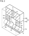
FIG. 2 is a perspective view of a flow path and a valve chamber in the gate valve inFIG. 1A ; -
FIG. 3 is a cross-sectional view of the gate valve inFIG. 1A in a closed state; -
FIG. 4A is a cross-sectional view of the gate valve inFIG. 1A in an open state, andFIG. 4B is a schematic view illustrating flow of fluid at a section taken along line IVB-IVB inFIG. 4A ; -
FIG. 5A is a sectional perspective view of a gate valve according to a second embodiment of the present invention, andFIG. 5B is a perspective view of a gate body and a stem inFIG. 5A ; -
FIG. 6 is a sectional perspective view of a flow path and a valve chamber in the gate valve inFIG. 5A ; -
FIG. 7 is a cross-sectional view of a gate valve according to a third embodiment of the present invention; and -
FIG. 8A is a sectional perspective view of a gate valve according to a fourth embodiment of the present invention, andFIG. 8B is a perspective view of a gate body inFIG. 8A . - Preferred embodiments of the present invention will be described in detail below with reference to the accompanying drawings. The ratio of the dimensions in the drawings may be exaggerated and differ from the actual ratio for ease of explanation. In the description below, a direction along which a gate is pushed into a flow path is referred to as "downward" or "lower side", and a direction along which the gate is retracted toward a valve body is referred to as "upward" or "upper side". However, this does not limit the direction the gate valve faces when the gate valve is installed.
- As illustrated in
FIG. 1A , agate valve 10 according to this embodiment includes avalve body 14 with alinear flow path 12, agate 16 configured to move up and down in the axial direction orthogonal to theflow path 12 to open and close theflow path 12, avalve chamber 18 accommodating thegate 16, and astem 20 extending from aproximal end portion 16a of thegate 16 in the axial direction. Fluid flowing through theflow path 12 includes gas such as air and steam (including vapor), gas at reduced pressure such as vacuum pressure, liquid such as water and oil, and fluid such as gel and mixtures of solid particles and liquid. Thegate valve 10 opens and closes to allow the fluid to flow and to stop the fluid from flowing. - The
gate 16 can move up and down in a direction of an axis A perpendicular to theflow path 12. When thegate 16 moves downward to the lower end, the outer surface of thegate 16 comes into contact with an inner wall (inner surface) 12a of theflow path 12 to close theflow path 12. Thegate 16 includes agate body 22 made of, for example, metal or resin, and aseal member 24 covering the outer surface of thegate body 22. Thegate 16 may include only thegate body 22 made of metal or resin without being covered. In this case, thegate body 22 of thegate 16 directly comes into contact with theflow path 12 in thevalve body 14 to close theflow path 12. - As illustrated in
FIG. 1B , thegate body 22 has circular symmetry around the axis A. Thegate body 22 includes, adjacent to aproximal end portion 22a, atapered portion 22c which has a diameter gradually decreasing toward adistal end 22b. Thegate body 22 includes, adjacent to thedistal end 22b, adistal end portion 22d which has a spherical outer surface. It is preferable that the spherical surface of thedistal end portion 22d have a radius of curvature larger than or equal to that of theinner wall 12a of theflow path 12 to reliably bring thedistal end 22b of thegate body 22 into firm contact with theinner wall 12a. Thegate body 22 is not limited to having circular symmetry around the axis A and may have any other shape streamlined along the direction of flow in theflow path 12. In this case, thegate body 22 may have, for example, an elliptical shape elongated in the direction of the flow path. - The border part connecting the tapered
portion 22c and thedistal end portion 22d has a smoothly continuing curved surface. It is preferable that the outer surfaces of the taperedportion 22c and thedistal end portion 22d be streamlined curved surfaces to prevent turbulence in the fluid flowing near thegate 16. As illustrated inFIG. 1C , thegate body 22 has a circular outer shape when viewed from thedistal end 22b. Thus, thegate 16 has a circular cross-section when cut in a direction perpendicular to the axis A. - The
seal member 24 covers the outer circumferential portion of thegate body 22 to constitute the outer surface of thegate 16. Theseal member 24 may be made of, for example, an elastically deformable material including rubber, elastomers, nylon, polyethylene, and fluoropolymers such as polytetrafluoroethylene. Theseal member 24 may be formed by coating the surface of thegate body 22 with the above-described material. Theseal member 24 may be a cap member produced using the above-described material and attached to the surface of thegate body 22. - The structure of the
gate 16 is not limited to that including theseal member 24 disposed on the surface of thegate body 22, and theseal member 24 may not necessarily be disposed on the surface as a separate member. That is, thegate body 22 may be made of the above-described elastically deformable material. In addition, thegate body 22 may be made only of metal or resin. - The
stem 20 extends from theproximal end portion 22a of thegate body 22. Thestem 20 is cylindrical and extends linearly upward in the direction of the axis A of thegate 16. Thestem 20 may be integrated with thegate body 22. Thestem 20 extends to the outside of thevalve body 14, and a drive mechanism (not illustrated) is attached to anend portion 20a of thestem 20. The drive mechanism drives thestem 20 and thegate 16 in the direction of the axis A. A packing 26 is attached to an outer circumferential portion of thestem 20. As illustrated inFIG. 1A , the packing 26 is brought into contact with a through-hole 28 for placing thestem 20 through thevalve body 14, thereby airtightly and fluid-tightly sealing thevalve chamber 18. - As illustrated in
FIG. 2 , thevalve body 14 includes theflow path 12, thevalve chamber 18, and the through-hole 28. Theflow path 12 has a linear shape and passes through thevalve body 14 from afirst side portion 14c to asecond side portion 14d. Theflow path 12 has a circular cross-section. The cross-section of theflow path 12 is not limited to circular and may be rectangular or polygonal. Theflow path 12 includes aseal groove 30 at a position close to the middle. Theseal groove 30 is created in a part brought into contact with thegate 16. Theseal groove 30 extends in the circumferential direction of theflow path 12, and the upper end thereof is connected to anopening portion 18c of thevalve chamber 18. The surface of theseal groove 30 may have a curvature. In this case, it is preferable that the curvature of the curved surface of theseal groove 30 be equal to that of the outer surface of thegate 16 to bring the outer surface of thegate 16 into firm surface contact with the surface of theseal groove 30. This improves sealing performance. - The surface of the
seal groove 30 may not necessarily be a curved surface and may be a flat surface such as a slope. The surface of theseal groove 30 is not limited to the curved surface and may have any shape that can be brought into contact with the outer surface of thegate 16. In a case where the pressure of the fluid in theflow path 12 is low, that is, thegate 16 does not receive a high pressure, theseal groove 30 may not necessarily be provided. - The
valve chamber 18 is disposed above theflow path 12. Thevalve chamber 18 includes aninclined portion 18b connected to theflow path 12, and acylindrical portion 18a including a cylindrical hollow and disposed above and connected to theinclined portion 18b. Thecylindrical portion 18a includes a cylindrical hollow extending in the direction of the axis A and has an inner diameter slightly larger than the diameter of theproximal end portion 16a of thegate 16. Theinclined portion 18b has a funnel shape with an inner diameter decreasing toward the bottom along the direction of the axis A. - The lower end part of the
inclined portion 18b serves as theopening portion 18c opened in theflow path 12. Thevalve chamber 18 communicates with theflow path 12 via theopening portion 18c. It is preferable that the inclination angle (angle with respect to the axis A) of the inner surface (tapered surface) of theinclined portion 18b be substantially equal to the inclination angle (angle with respect to the axis A) of the taperedportion 22c of thegate body 22. When thegate 16 is pushed downward to the lower end, the taperedportion 22c of thegate body 22 comes into surface contact with theinclined portion 18b to close the openingportion 18c of thevalve chamber 18. The volume of thevalve chamber 18 is substantially equal to the volume of thegate 16. - The through-
hole 28 is formed above a central portion of the upper end of thevalve chamber 18. The through-hole 28 has an inner diameter substantially equal to the diameter of thestem 20 and passes through thevalve body 14 toward an upper portion of thevalve body 14. Thestem 20 is fitted in the through-hole 28. - For example, the
valve body 14 may include two members, that is, afirst portion 14a extending to the upper end of thevalve chamber 18 and asecond portion 14b covering the upper end of thevalve chamber 18. To install thegate 16 in thegate valve 10, thesecond portion 14b is separated from thefirst portion 14a so that the upper end of thevalve chamber 18 becomes open. After thegate 16 is inserted into thevalve chamber 18, thesecond portion 14b is mounted on thefirst portion 14a and secured to thefirst portion 14a. Thegate 16 can be fitted in thevalve chamber 18 in this manner. - Next, the effects of the
gate valve 10 configured as above will be described. - As illustrated in
FIG. 3 , while thegate 16 is completely lowered, theseal member 24 of thegate 16 is in contact with theinner wall 12a of theflow path 12 and theinclined portion 18b, and thereby theflow path 12 is closed by thegate 16. At this time, the surface of theseal member 24 enters theseal groove 30 to come into surface contact with theseal groove 30. Thus, even when theseal member 24 receives a force caused by the pressure of fluid upstream of theflow path 12, theseal member 24 held by theseal groove 30 does not deform, and the sealing performance is maintained. At this moment, the upstream pressure remains in thevalve chamber 18, and thegate 16 receives a biasing force pushing thegate 16 downward. Thus, in a case where the pressure of fluid flowing in theflow path 12 is high, the sealing performance further improves. - The downward biasing force caused by the pressure remaining in the
valve chamber 18 and acting on thegate 16 can be adjusted as appropriate by changing the area of theproximal end portion 16a of thegate 16. That is, the area of theproximal end portion 16a of thegate 16 decreases by increasing the diameter of thestem 20, and the downward biasing force acting on thegate 16 decreases accordingly. While closed, thegate 16 receives a force pushing thegate 16 upward caused by the pressure from the fluid upstream of theflow path 12. Thus, the upward force caused by the pressure from the upstream fluid and the downward biasing force caused by the pressure in thevalve chamber 18 may be balanced (made substantially equal) by adjusting the area of theproximal end portion 16a of thegate 16 as appropriate. In this case, thegate 16 can be pulled upward from the closed state with a small operating force. - As illustrated in
FIG. 4A , when thegate 16 moves up and stops in mid-stroke, thegate 16 is separated from theinner wall 12a of theflow path 12, and fluid can flow through theflow path 12. At this moment, a gap is created between theinclined portion 18b and thegate 16, causing thevalve chamber 18 to communicate with theflow path 12. As a result, the internal pressure of thevalve chamber 18 and the internal pressure of theflow path 12 become equal. - As the
gate 16 has rotation symmetry (circular symmetry), the cross-section thereof is circular as illustrated inFIG. 4B . This prevents turbulence in the fluid flowing around thegate 16 and maintains regulated flow. As the fluid flows smoothly around thegate 16, raising thegate 16 only slightly allows a larger volume of fluid to flow through theflow path 12. - The
gate valve 10 produces the following effects. - The
gate valve 10 includes thegate 16 having a curved outer surface streamlined along theflow path 12. This prevents turbulence in the fluid flowing around thegate 16 and allows a larger volume of fluid to flow through theflow path 12 even when thegate 16 stops in mid-stroke. As a result, theflow path 12 can be opened and closed with short strokes. In addition, a reduction in the stroke range leads to a reduction in the size of the drive mechanism of thegate 16. - Furthermore, the shape of the
gate 16 is symmetric with respect to the direction of flow in theflow path 12. This allows thegate 16 to face any direction with respect to thevalve body 14 and facilitates assembly of thegate 16 to thevalve body 14. Thegate 16 operates in the same manner regardless of in which direction fluid flows through theflow path 12. - In the
gate valve 10, thedistal end 22b of thegate 16 may be spherical. This further prevents turbulence in the fluid flowing around thegate 16. The part brought into contact with theflow path 12 is limited to a linear area (portion of the seal groove 30) extending in the circumferential direction of theflow path 12. Thus, the surface pressure at the contact part easily increases. This results in high sealing performance even in a case where the pressure of the fluid increases. - In the
gate valve 10, the seal groove (recess) 30 hollowed outward in a radial direction of theflow path 12 may be formed at a part of the inner surface of theflow path 12, the part being brought into contact with the outer surface of thegate 16. The seal groove (recess) 30 may extend in the circumferential direction of theflow path 12 to have a groove shape. Theseal groove 30 with the above-described structure holds the surface of theseal member 24 of thegate 16. This prevents deformation of theseal member 24 caused by the fluid pressure and thus improves the sealing performance. - The curvature of the seal groove (recess) 30 in the
flow path 12 may be substantially equal to the curvature of the outer surface of thegate 16 at the part thereof brought into contact with the seal groove (recess) 30. This brings the outer surface of thegate 16 into firm contact with theseal groove 30, resulting in an improvement in sealing performance. - The
valve chamber 18 may include theinclined portion 18b, and when thegate 16 is lowered to theflow path 12, the outer surface of the taperedportion 22c of thegate 16 may come into contact with theinclined portion 18b of thevalve chamber 18 so that thevalve chamber 18 is closed. This prevents fluid from flowing via thevalve chamber 18. By raising thegate 16, thevalve chamber 18 communicates with theflow path 12, and the internal pressure of thevalve chamber 18 and the internal pressure of theflow path 12 become equal. As a result, an increase in vertical movement of thegate 16 is prevented even when the fluid pressure becomes higher, and thegate 16 can be operated with a small operating force. - A reduction in the stroke leads to a reduction in the height of the
cylindrical portion 18a of thevalve chamber 18. This reduces the size of a dead space inside thevalve body 14, that is, the size of a liquid remaining spot. As a result, thegate valve 10 provides excellent replacement performance and allows fluid to flow without residual fluid remaining inside thevalve body 14. - As illustrated in
FIG. 5A , agate valve 40 according to this embodiment differs from thegate valve 10 inFIG. 1A in the shape of agate 16A and the shape of arecess 50 created in theflow path 12. In thegate valve 40, the same reference numbers and symbols are used for structures similar to those of thegate valve 10 inFIG. 1A , and the detailed descriptions will be omitted. - As illustrated in
FIG. 5B , thegate 16A includes agate body 44 with aflat surface 44a at the distal end thereof. Thegate body 44 is tapered from aproximal end portion 44b to theflat surface 44a at the distal end such that the diameter gradually decreases. As illustrated inFIG. 5A , the surface of thegate body 44 is covered with aseal member 46. - As illustrated in
FIG. 6 , avalve body 14A includes asecond member 42 with theflow path 12. Thesecond member 42 includes therecess 50 in a middle portion at the lower end of theinner wall 12a of theflow path 12 to accommodate theflat surface 44a at the distal end of thegate body 44. Therecess 50 has an inner diameter substantially equal to the diameter of theflat surface 44a of thegate body 44. Avalve chamber 48 is disposed above a middle portion of theflow path 12. Thevalve chamber 48 includes aninclined portion 48b communicating with theflow path 12 via anopening portion 48c, and acylindrical portion 48a formed above theinclined portion 48b. Theinclined portion 48b extends along theinner wall 12a of theflow path 12 in the circumferential direction of theflow path 12 and communicates with therecess 50. - The inner diameter of the
cylindrical portion 48a is slightly larger than the diameter of theproximal end portion 44b of thegate 16A. The angle (angle with respect to the axis A) of the tapered surface of theinclined portion 48b is substantially equal to the inclination angle (angle with respect to the axis A) of the sidewall of thegate body 44 of thegate 16A. Thus, when thegate 16A is pushed downward, thegate 16A comes into surface contact with theinclined portion 48b to close thevalve chamber 48. At this moment, thegate 16A comes into surface contact with theinclined portion 48b extending in the circumferential direction of theflow path 12 and therecess 50 to completely close theflow path 12. That is, theflat surface 44a of thegate body 44 comes into contact with therecess 50, which has a diameter equal to the diameter of theflat surface 44a, to airtightly and fluid-tightly close theflow path 12. - The structures of the
gate body 44 and therecess 50 of this embodiment are not limited to the above. The side surface of therecess 50 may be tapered such that the diameter gradually decreases in a direction away from theflow path 12, and the bottom surface of therecess 50 may have a diameter smaller than the diameter of theflat surface 44a. In this case, theflat surface 44a of thegate body 44 comes into contact with the tapered side surface of therecess 50 to airtightly and fluid-tightly close theflow path 12. At this time, thegate body 44 is not necessarily in contact with the bottom surface of therecess 50. The above-described structure provides sufficient airtightness and fluid tightness even in a case where accuracy in machining therecess 50 and thegate body 44 is relatively low. - The
gate valve 40 configured as above produces the following effects. - The
gate 16A of thegate valve 40 is tapered such that the diameter decreases toward the distal end, and the distal end portion of thegate 16A is configured to be theflat surface 44a parallel to theflow path 12. This prevents turbulence in the fluid flowing around thegate 16A and allows a larger volume of fluid to flow through theflow path 12 even when thegate 16A stops in mid-stroke. As a result, theflow path 12 can be opened and closed with short strokes. - In the
gate valve 40, theflow path 12 also includes therecess 50 hollowed outward in a radial direction of theflow path 12, in the inner surface at the part brought into contact with the outer surface of thegate 16A. This results in high sealing performance even in the case where the pressure of the fluid increases. - As illustrated in
FIG. 7 , agate valve 60 according to this embodiment differs from thegate valve 10 inFIG. 1A in that theflow path 12 is provided with aseal portion 61. In thegate valve 60, the same reference numbers and symbols are used for structures similar to those of thegate valve 10 inFIG. 1A , and the detailed descriptions will be omitted. - In the
gate valve 60, avalve body 14B includes asecond member 42B with theflow path 12. Theflow path 12 includes aninstallation portion 12b formed by partially cutting off an inner circumferential portion of theflow path 12. Theseal portion 61 is fitted in theinstallation portion 12b. Theseal portion 61 is a substantially cylindrical member and is made of, for example, an elastically deformable material including rubber, elastomers, nylon, polyethylene, and fluoropolymers such as polytetrafluoroethylene. - The
seal portion 61 includes acylindrical body part 62, aflow path 64 formed inside thebody part 62, arecess 66 brought into contact with the distal end of thegate 16, and anopening part 68 communicating with thevalve chamber 18. Thebody part 62 has a radial thickness and an axial length respectively equal to the radial depth and the axial length of the cut-off portion constituting theinstallation portion 12b. Thebody part 62 includes theflow path 64 passing through thebody part 62 in a direction parallel to the axis of theflow path 12. The inner circumferential surface of theflow path 64 is flush with the inner circumferential surface of theflow path 12. Therecess 66 is created in the inner circumferential surface of theflow path 64 at a part brought into contact with thegate 16. Therecess 66 has a shape similar to the shape of theseal groove 30 inFIG. 2 and extends in the circumferential direction of theflow path 64. Moreover, the inner surface of therecess 66 has a curvature substantially equal to the curvature of the distal end portion of thegate 16. Thegate 16 may includeonly gate body 22 without theseal member 24. - The opening
part 68 is formed in an upper part of thebody part 62 and passes through thebody part 62 in the axial direction of thegate 16. The inner circumferential surface of theopening part 68 is inclined at the same angle as the surface of theinclined portion 18b of thevalve chamber 18 and is flush with the surface of theinclined portion 18b. When thegate 16 is pushed downward to the closed position, the taperedportion 22c adjacent to theproximal end portion 16a of thegate 16 comes into surface contact with the inner circumferential surface of theopening part 68 to airtightly or fluid-tightly close thevalve chamber 18. - According to the
gate valve 60 configured as above, theseal portion 61 can be brought into firm contact with thegate 16 in an airtight or fluid tight manner. This ensures the sealing performance even in a case where theseal member 24 is not formed on the surface of thegate 16. - As illustrated in
FIG. 8A , agate valve 70 according to this embodiment differs from thegate valve 40 inFIGS. 5A and 5B in the structure of agate 16B and in that thegate valve 70 includes acommunication path 72. In thegate valve 70, the same reference numbers and symbols are used for structures similar to those of thegate valve 40 inFIGS. 5A and 5B , and the detailed descriptions will be omitted. - As illustrated in
FIG. 8B , thegate 16B includes thegate body 44 with theflat surface 44a at the distal end thereof. Thegate body 44 is tapered from theproximal end portion 44b to theflat surface 44a at the distal end such that the diameter gradually decreases. In this embodiment, only aside surface 44c of thegate body 44 is covered with theseal member 46. Theproximal end portion 44b and theflat surface 44a of thegate body 44 are not covered with theseal member 46, and theflat surface 44a directly comes into contact with therecess 50. - As illustrated in
FIG. 8A , thevalve body 14B includes thecommunication path 72 enabling communication between theflow path 12 and thevalve chamber 48. A first end of thecommunication path 72 communicates with the upstream part of theflow path 12, and a second end thereof communicates with thevalve chamber 48. The structure of thesecond member 42 of thevalve body 14B other than the above is similar to the structure of thesecond member 42 illustrated inFIG. 6 . - The
gate valve 70 configured as above produces the following effects. - In the
gate valve 70 of this embodiment, thevalve body 14B includes thecommunication path 72 enabling communication between theflow path 12 and thevalve chamber 48. When thegate 16B is completely pushed down to close theflow path 12, thecommunication path 72 transfers the pressure in the upstream part of theflow path 12 to thevalve chamber 48. As a result, thegate 16B is biased in a direction along which thegate 16B closes theflow path 12 due to the difference in pressure between thevalve chamber 48 and the downstream part of theflow path 12. This improves sealing performance of thegate 16B and enables thegate 16B to close theflow path 12 more reliably. - In the
gate 16B of this embodiment, theside surface 44c that is brought into surface contact with thevalve chamber 48 and theinclined portion 48b to close theflow path 12 is covered with theseal member 46. This ensures sufficient sealing performance. - The application of the
communication path 72 is not limited to this embodiment, and thecommunication path 72 may be provided for thegate valves FIGS. 1A to 7 . In this case, effects similar to those produced by thegate valve 70 can be achieved. - The embodiments of the present invention are not limited in particular to those described above, and various modifications can be made thereto. For example, the
gate body 44 that is not covered with theelastic seal member 46 as illustrated inFIG. 5B may be used as thegate 16B. In this case, the metal surface of thegate body 44 directly comes into contact with theinclined portion 48b of thevalve chamber 48 and the recess 50 (seeFIG. 6 ) to airtightly and fluid-tightly close theflow path 12. - Moreover, for example, the
gate body 22 illustrated inFIG. 1B may be used as thegate 16. In this case, the metal surface of thegate body 22 directly comes into contact with theseal groove 30 in thevalve chamber 18 to airtightly and fluid-tightly close theflow path 12. The surface of thegate body 44 is not easily deformed by friction or pressure compared with the case where thegate body 44 is covered with theseal member 46 made of a material such as rubber and resin. Thus, thegate body 44 that is not covered with theseal member 46 achieves a gate valve with excellent wear and pressure resistances.
Claims (11)
- A gate valve comprising:a valve body (14) including a flow path (12) with a linear shape, and a valve chamber (18) disposed in a side portion of the flow path (12);a gate (16) accommodated in the valve chamber (18) and configured to move in an axial direction perpendicular to the flow path (12) to close the flow path (12) by bringing an outer surface of the gate (16) into contact with an inner surface of the flow path (12); anda stem (20) extending from a proximal end portion (16a) of the gate (16) in the axial direction, whereinthe outer surface of the gate (16) at a part thereof protruding toward the flow path (12) when the gate (16) is in an open position is configured as a streamlined curved surface.
- The gate valve according to claim 1, wherein a distal end portion of the gate (16) is configured to be a spherical surface.
- The gate valve according to claim 1, wherein the gate (16) has a tapered shape with a diameter decreasing toward a distal end, and a distal end portion of the gate (16) is configured to be a flat surface parallel to the flow path (12).
- The gate valve according to any one of claims 1 to 3, wherein a recess (30) hollowed outward in a radial direction of the flow path (12) is formed at a part of the inner surface of the flow path (12), the part being brought into contact with the outer surface of the gate (16).
- The gate valve according to claim 4, wherein the recess (30) extends in a circumferential direction of the flow path (12) to have a groove shape.
- The gate valve according to claim 5, wherein a curvature of the recess (30) is substantially equal to a curvature of the outer surface of the gate (16) at a part thereof brought into contact with the recess (30).
- The gate valve according to claim 1, wherein:
the valve chamber (18) includes a tapered surface with a diameter decreasing toward the flow path (12); and
when the gate (16) is lowered to the flow path (12), a tapered portion of the gate (16) comes into contact with the tapered surface of the valve chamber (18) to close the valve chamber (18). - The gate valve according to claim 7, wherein a volume of the valve chamber (18) is substantially equal to a volume of the gate (16).
- The gate valve according to any one of claims 1 to 8, wherein the flow path (12) includes a seal portion (61) brought into firm contact with the gate (16) in an airtight or fluid tight manner.
- The gate valve according to any one of claims 1 to 9, wherein, while the gate valve is closed, a force pushing up the gate (16) toward the valve chamber (18) caused by a pressure from fluid in an upstream part of the flow path (12) and a force biasing the gate (16) toward the flow path (12) caused by a pressure in the valve chamber (18) are balanced.
- The gate valve according to any one of claims 1 to 9, further comprising a communication path (72) enabling communication between the valve chamber (18, 48) and an upstream part of the flow path (12), wherein
while the gate valve is closed, the gate (16) is biased toward the flow path (12) by a pressure in the valve chamber (18, 48).
Applications Claiming Priority (2)
| Application Number | Priority Date | Filing Date | Title |
|---|---|---|---|
| JP2018091346 | 2018-05-10 | ||
| PCT/JP2019/018664 WO2019216398A1 (en) | 2018-05-10 | 2019-05-10 | Gate valve |
Publications (2)
| Publication Number | Publication Date |
|---|---|
| EP3792532A1 true EP3792532A1 (en) | 2021-03-17 |
| EP3792532A4 EP3792532A4 (en) | 2022-02-09 |
Family
ID=68468180
Family Applications (1)
| Application Number | Title | Priority Date | Filing Date |
|---|---|---|---|
| EP19799885.9A Pending EP3792532A4 (en) | 2018-05-10 | 2019-05-10 | Gate valve |
Country Status (9)
| Country | Link |
|---|---|
| US (1) | US11353122B2 (en) |
| EP (1) | EP3792532A4 (en) |
| JP (2) | JP7620182B2 (en) |
| KR (2) | KR20210006978A (en) |
| CN (1) | CN112105854B (en) |
| BR (1) | BR112020022798A2 (en) |
| MX (1) | MX2020011988A (en) |
| TW (1) | TWI698607B (en) |
| WO (1) | WO2019216398A1 (en) |
Families Citing this family (4)
| Publication number | Priority date | Publication date | Assignee | Title |
|---|---|---|---|---|
| KR102352372B1 (en) * | 2021-06-11 | 2022-01-18 | 박종환 | Valve system for easier parts replacement with improved order role |
| KR102352374B1 (en) * | 2021-06-11 | 2022-01-18 | 박종환 | Valve method with easy replacement structure with improved order role |
| KR102352373B1 (en) * | 2021-06-11 | 2022-01-18 | 박종환 | Valve device for easier parts replacement with improved order role |
| KR20250113806A (en) * | 2024-01-19 | 2025-07-28 | 한국원자력연구원 | Inadvertent actuation block valve and nuclear energy facility having the same |
Family Cites Families (38)
| Publication number | Priority date | Publication date | Assignee | Title |
|---|---|---|---|---|
| US1089160A (en) * | 1911-01-18 | 1914-03-03 | Jean Scherr | Tap and valve. |
| US2124334A (en) * | 1936-10-05 | 1938-07-19 | C C Brown | Valve mechanism |
| US2420849A (en) * | 1943-09-25 | 1947-05-20 | Everlasting Valve Co | Valve |
| US2911186A (en) * | 1956-07-13 | 1959-11-03 | Hydril Co | Gate valve |
| US3006597A (en) * | 1957-01-07 | 1961-10-31 | Cooper Alloy Corp | Valve |
| US3043555A (en) * | 1957-11-15 | 1962-07-10 | Stubbe Friedrich | Gate valve having an upsettable sealing member of rubber elastic material |
| US3217735A (en) * | 1963-12-18 | 1965-11-16 | Nibco | Valve |
| JPS4535Y1 (en) * | 1965-02-22 | 1970-01-06 | ||
| US3420499A (en) * | 1966-02-28 | 1969-01-07 | Nibco | Valve |
| US3380710A (en) * | 1966-02-28 | 1968-04-30 | Nibco | Valve |
| JPS4847517U (en) * | 1971-10-06 | 1973-06-22 | ||
| BE795109A (en) * | 1972-02-07 | 1973-05-29 | Whitey Research Tool Co | VALVE VALVE |
| US3826274A (en) * | 1973-03-26 | 1974-07-30 | A Moen | Shower-tub diverter valve |
| NL152066B (en) * | 1973-03-30 | 1977-01-17 | Ind En Handelsonderneming Conv | PLUG VALVE WITH A PLUG OF AN ELASTOMER MATERIAL. |
| CH596273A5 (en) | 1974-02-28 | 1978-03-15 | Ciba Geigy Ag | |
| JPS50121324U (en) * | 1974-03-18 | 1975-10-03 | ||
| JPS532730U (en) * | 1976-06-28 | 1978-01-11 | ||
| JPS55130964U (en) * | 1979-03-07 | 1980-09-16 | ||
| JPS6020630B2 (en) * | 1980-04-08 | 1985-05-23 | 旭有機材工業株式会社 | gate valve |
| JPS58169268U (en) * | 1982-05-07 | 1983-11-11 | 前沢化成工業株式会社 | Gate valve device |
| JPS6051364U (en) * | 1983-09-19 | 1985-04-11 | 旭有機材工業株式会社 | gate valve |
| JPS6084482A (en) * | 1983-10-15 | 1985-05-13 | Yamatake Honeywell Co Ltd | Valve |
| JPS60129473A (en) * | 1983-12-15 | 1985-07-10 | Asahi Organic Chem Ind Co Ltd | Valve device |
| JPS60139961U (en) * | 1984-02-29 | 1985-09-17 | 株式会社山武 | valve |
| YU65484A (en) * | 1984-04-10 | 1988-08-31 | Mladen Jankovic | Integrated bolt |
| JPH0242928Y2 (en) * | 1985-10-31 | 1990-11-15 | ||
| CN2088182U (en) * | 1991-02-01 | 1991-11-06 | 北京顺义天竺阀门厂 | Gate valve |
| US5439024A (en) * | 1992-12-09 | 1995-08-08 | Tri-Clover, Inc. | Sanitary gate valve with tapered valve plug |
| JPH06265029A (en) | 1993-03-09 | 1994-09-20 | Sekisui Chem Co Ltd | Gate valve |
| GB9514390D0 (en) * | 1995-07-13 | 1995-09-13 | Market Linc Valvetec Ltd | Valve |
| JP2005155737A (en) * | 2003-11-25 | 2005-06-16 | Meiwa Seisakusho:Kk | Gate valve |
| JP2006057739A (en) * | 2004-08-20 | 2006-03-02 | Pacific Ind Co Ltd | Control valve |
| CA2568681C (en) * | 2006-11-23 | 2008-02-19 | Domino Machine Inc. | Gate valve with offset valve stem |
| US7255329B1 (en) * | 2006-11-23 | 2007-08-14 | Domino Machine Inc. | Gate valve with offset valve stem |
| US20130240768A1 (en) * | 2011-09-14 | 2013-09-19 | Energyneering Solutions, Inc. | High Density Polyethylene Gate Valve |
| CN102494150A (en) * | 2011-12-07 | 2012-06-13 | 深圳大学 | Gate valve with novel sealing structure |
| CN206377291U (en) * | 2016-07-14 | 2017-08-04 | 福建省金牛机械发展有限公司 | A kind of flap is the dark bar plough groove type elastic sealing gate valve of spherical structure |
| CN206361176U (en) * | 2016-11-12 | 2017-07-28 | 唐工阀门有限公司 | Pneumatic type gate plate type gate valve |
-
2019
- 2019-05-10 WO PCT/JP2019/018664 patent/WO2019216398A1/en not_active Ceased
- 2019-05-10 US US17/054,082 patent/US11353122B2/en active Active
- 2019-05-10 JP JP2020518345A patent/JP7620182B2/en active Active
- 2019-05-10 BR BR112020022798-6A patent/BR112020022798A2/en not_active Application Discontinuation
- 2019-05-10 MX MX2020011988A patent/MX2020011988A/en unknown
- 2019-05-10 KR KR1020207035463A patent/KR20210006978A/en not_active Ceased
- 2019-05-10 CN CN201980031115.8A patent/CN112105854B/en active Active
- 2019-05-10 TW TW108116234A patent/TWI698607B/en active
- 2019-05-10 EP EP19799885.9A patent/EP3792532A4/en active Pending
- 2019-05-10 KR KR1020237020172A patent/KR102639548B1/en active Active
-
2023
- 2023-10-11 JP JP2023175983A patent/JP7666567B6/en active Active
Also Published As
| Publication number | Publication date |
|---|---|
| CN112105854B (en) | 2022-11-18 |
| EP3792532A4 (en) | 2022-02-09 |
| JP2023182761A (en) | 2023-12-26 |
| JP7666567B2 (en) | 2025-04-22 |
| JP7620182B2 (en) | 2025-01-23 |
| MX2020011988A (en) | 2021-01-29 |
| TW201947143A (en) | 2019-12-16 |
| CN112105854A (en) | 2020-12-18 |
| KR20210006978A (en) | 2021-01-19 |
| KR102639548B1 (en) | 2024-02-22 |
| US20210190214A1 (en) | 2021-06-24 |
| KR20230092032A (en) | 2023-06-23 |
| JPWO2019216398A1 (en) | 2021-05-13 |
| WO2019216398A1 (en) | 2019-11-14 |
| JP7666567B6 (en) | 2025-06-06 |
| TWI698607B (en) | 2020-07-11 |
| BR112020022798A2 (en) | 2021-02-02 |
| US11353122B2 (en) | 2022-06-07 |
Similar Documents
| Publication | Publication Date | Title |
|---|---|---|
| US11353122B2 (en) | Gate valve | |
| US8550117B2 (en) | Seal assembly for a fluid pressure control device | |
| US11828373B2 (en) | Check valve | |
| US10072766B2 (en) | Valve | |
| US10989317B2 (en) | Two-way valve | |
| CN108825803B (en) | Water outlet valve structure and humidifier comprising same | |
| EP4711653A1 (en) | Valve | |
| US12292124B2 (en) | Check valve | |
| CN212804417U (en) | Valve body assembly and valve body assembly | |
| KR101617924B1 (en) | Pilot-type electromagnetic valve | |
| US20250052326A1 (en) | Metering Valve | |
| KR102338790B1 (en) | Valve with Metal Seal for Improving Airtightness Efficiency | |
| KR200348821Y1 (en) | Needle valve | |
| JP2015021545A (en) | Check valve, cap body, and manufacturing method of cap | |
| AU2011204925B2 (en) | Ventil | |
| CN113586749A (en) | Valve core for valve and valve with same |
Legal Events
| Date | Code | Title | Description |
|---|---|---|---|
| STAA | Information on the status of an ep patent application or granted ep patent |
Free format text: STATUS: THE INTERNATIONAL PUBLICATION HAS BEEN MADE |
|
| PUAI | Public reference made under article 153(3) epc to a published international application that has entered the european phase |
Free format text: ORIGINAL CODE: 0009012 |
|
| STAA | Information on the status of an ep patent application or granted ep patent |
Free format text: STATUS: REQUEST FOR EXAMINATION WAS MADE |
|
| 17P | Request for examination filed |
Effective date: 20201203 |
|
| AK | Designated contracting states |
Kind code of ref document: A1 Designated state(s): AL AT BE BG CH CY CZ DE DK EE ES FI FR GB GR HR HU IE IS IT LI LT LU LV MC MK MT NL NO PL PT RO RS SE SI SK SM TR |
|
| AX | Request for extension of the european patent |
Extension state: BA ME |
|
| DAV | Request for validation of the european patent (deleted) | ||
| DAX | Request for extension of the european patent (deleted) | ||
| A4 | Supplementary search report drawn up and despatched |
Effective date: 20220111 |
|
| RIC1 | Information provided on ipc code assigned before grant |
Ipc: F16K 27/04 20060101ALI20220104BHEP Ipc: F16K 3/314 20060101AFI20220104BHEP |
|
| STAA | Information on the status of an ep patent application or granted ep patent |
Free format text: STATUS: EXAMINATION IS IN PROGRESS |
|
| 17Q | First examination report despatched |
Effective date: 20240322 |
|
| RAP3 | Party data changed (applicant data changed or rights of an application transferred) |
Owner name: SMC CORPORATION |