EP3792462A1 - Dosing and mixing assemblies for exhaust aftertreatment system - Google Patents
Dosing and mixing assemblies for exhaust aftertreatment system Download PDFInfo
- Publication number
- EP3792462A1 EP3792462A1 EP19197416.1A EP19197416A EP3792462A1 EP 3792462 A1 EP3792462 A1 EP 3792462A1 EP 19197416 A EP19197416 A EP 19197416A EP 3792462 A1 EP3792462 A1 EP 3792462A1
- Authority
- EP
- European Patent Office
- Prior art keywords
- conduit
- flow path
- exhaust
- arrangement
- zone
- Prior art date
- Legal status (The legal status is an assumption and is not a legal conclusion. Google has not performed a legal analysis and makes no representation as to the accuracy of the status listed.)
- Withdrawn
Links
Images








Classifications
-
- F—MECHANICAL ENGINEERING; LIGHTING; HEATING; WEAPONS; BLASTING
- F01—MACHINES OR ENGINES IN GENERAL; ENGINE PLANTS IN GENERAL; STEAM ENGINES
- F01N—GAS-FLOW SILENCERS OR EXHAUST APPARATUS FOR MACHINES OR ENGINES IN GENERAL; GAS-FLOW SILENCERS OR EXHAUST APPARATUS FOR INTERNAL-COMBUSTION ENGINES
- F01N3/00—Exhaust or silencing apparatus having means for purifying, rendering innocuous, or otherwise treating exhaust
- F01N3/08—Exhaust or silencing apparatus having means for purifying, rendering innocuous, or otherwise treating exhaust for rendering innocuous
- F01N3/10—Exhaust or silencing apparatus having means for purifying, rendering innocuous, or otherwise treating exhaust for rendering innocuous by thermal or catalytic conversion of noxious components of exhaust
- F01N3/24—Exhaust or silencing apparatus having means for purifying, rendering innocuous, or otherwise treating exhaust for rendering innocuous by thermal or catalytic conversion of noxious components of exhaust characterised by constructional aspects of converting apparatus
- F01N3/28—Construction of catalytic reactors
- F01N3/2892—Exhaust flow directors or the like, e.g. upstream of catalytic device
-
- F—MECHANICAL ENGINEERING; LIGHTING; HEATING; WEAPONS; BLASTING
- F01—MACHINES OR ENGINES IN GENERAL; ENGINE PLANTS IN GENERAL; STEAM ENGINES
- F01N—GAS-FLOW SILENCERS OR EXHAUST APPARATUS FOR MACHINES OR ENGINES IN GENERAL; GAS-FLOW SILENCERS OR EXHAUST APPARATUS FOR INTERNAL-COMBUSTION ENGINES
- F01N13/00—Exhaust or silencing apparatus characterised by constructional features
- F01N13/009—Exhaust or silencing apparatus characterised by constructional features having two or more separate purifying devices arranged in series
-
- F—MECHANICAL ENGINEERING; LIGHTING; HEATING; WEAPONS; BLASTING
- F01—MACHINES OR ENGINES IN GENERAL; ENGINE PLANTS IN GENERAL; STEAM ENGINES
- F01N—GAS-FLOW SILENCERS OR EXHAUST APPARATUS FOR MACHINES OR ENGINES IN GENERAL; GAS-FLOW SILENCERS OR EXHAUST APPARATUS FOR INTERNAL-COMBUSTION ENGINES
- F01N13/00—Exhaust or silencing apparatus characterised by constructional features
- F01N13/14—Exhaust or silencing apparatus characterised by constructional features having thermal insulation
- F01N13/141—Double-walled exhaust pipes or housings
- F01N13/143—Double-walled exhaust pipes or housings with air filling the space between both walls
-
- F—MECHANICAL ENGINEERING; LIGHTING; HEATING; WEAPONS; BLASTING
- F01—MACHINES OR ENGINES IN GENERAL; ENGINE PLANTS IN GENERAL; STEAM ENGINES
- F01N—GAS-FLOW SILENCERS OR EXHAUST APPARATUS FOR MACHINES OR ENGINES IN GENERAL; GAS-FLOW SILENCERS OR EXHAUST APPARATUS FOR INTERNAL-COMBUSTION ENGINES
- F01N3/00—Exhaust or silencing apparatus having means for purifying, rendering innocuous, or otherwise treating exhaust
- F01N3/08—Exhaust or silencing apparatus having means for purifying, rendering innocuous, or otherwise treating exhaust for rendering innocuous
- F01N3/10—Exhaust or silencing apparatus having means for purifying, rendering innocuous, or otherwise treating exhaust for rendering innocuous by thermal or catalytic conversion of noxious components of exhaust
- F01N3/18—Exhaust or silencing apparatus having means for purifying, rendering innocuous, or otherwise treating exhaust for rendering innocuous by thermal or catalytic conversion of noxious components of exhaust characterised by methods of operation; Control
- F01N3/20—Exhaust or silencing apparatus having means for purifying, rendering innocuous, or otherwise treating exhaust for rendering innocuous by thermal or catalytic conversion of noxious components of exhaust characterised by methods of operation; Control specially adapted for catalytic conversion
- F01N3/206—Adding periodically or continuously substances to exhaust gases for promoting purification, e.g. catalytic material in liquid form, NOx reducing agents
- F01N3/2066—Selective catalytic reduction [SCR]
-
- F—MECHANICAL ENGINEERING; LIGHTING; HEATING; WEAPONS; BLASTING
- F01—MACHINES OR ENGINES IN GENERAL; ENGINE PLANTS IN GENERAL; STEAM ENGINES
- F01N—GAS-FLOW SILENCERS OR EXHAUST APPARATUS FOR MACHINES OR ENGINES IN GENERAL; GAS-FLOW SILENCERS OR EXHAUST APPARATUS FOR INTERNAL-COMBUSTION ENGINES
- F01N2240/00—Combination or association of two or more different exhaust treating devices, or of at least one such device with an auxiliary device, not covered by indexing codes F01N2230/00 or F01N2250/00, one of the devices being
- F01N2240/20—Combination or association of two or more different exhaust treating devices, or of at least one such device with an auxiliary device, not covered by indexing codes F01N2230/00 or F01N2250/00, one of the devices being a flow director or deflector
-
- F—MECHANICAL ENGINEERING; LIGHTING; HEATING; WEAPONS; BLASTING
- F01—MACHINES OR ENGINES IN GENERAL; ENGINE PLANTS IN GENERAL; STEAM ENGINES
- F01N—GAS-FLOW SILENCERS OR EXHAUST APPARATUS FOR MACHINES OR ENGINES IN GENERAL; GAS-FLOW SILENCERS OR EXHAUST APPARATUS FOR INTERNAL-COMBUSTION ENGINES
- F01N2470/00—Structure or shape of exhaust gas passages, pipes or tubes
- F01N2470/02—Tubes being perforated
-
- F—MECHANICAL ENGINEERING; LIGHTING; HEATING; WEAPONS; BLASTING
- F01—MACHINES OR ENGINES IN GENERAL; ENGINE PLANTS IN GENERAL; STEAM ENGINES
- F01N—GAS-FLOW SILENCERS OR EXHAUST APPARATUS FOR MACHINES OR ENGINES IN GENERAL; GAS-FLOW SILENCERS OR EXHAUST APPARATUS FOR INTERNAL-COMBUSTION ENGINES
- F01N2470/00—Structure or shape of exhaust gas passages, pipes or tubes
- F01N2470/02—Tubes being perforated
- F01N2470/04—Tubes being perforated characterised by shape, disposition or dimensions of apertures
-
- F—MECHANICAL ENGINEERING; LIGHTING; HEATING; WEAPONS; BLASTING
- F01—MACHINES OR ENGINES IN GENERAL; ENGINE PLANTS IN GENERAL; STEAM ENGINES
- F01N—GAS-FLOW SILENCERS OR EXHAUST APPARATUS FOR MACHINES OR ENGINES IN GENERAL; GAS-FLOW SILENCERS OR EXHAUST APPARATUS FOR INTERNAL-COMBUSTION ENGINES
- F01N2470/00—Structure or shape of exhaust gas passages, pipes or tubes
- F01N2470/08—Exhaust gas passages being formed between the walls of an outer shell and an inner chamber
-
- F—MECHANICAL ENGINEERING; LIGHTING; HEATING; WEAPONS; BLASTING
- F01—MACHINES OR ENGINES IN GENERAL; ENGINE PLANTS IN GENERAL; STEAM ENGINES
- F01N—GAS-FLOW SILENCERS OR EXHAUST APPARATUS FOR MACHINES OR ENGINES IN GENERAL; GAS-FLOW SILENCERS OR EXHAUST APPARATUS FOR INTERNAL-COMBUSTION ENGINES
- F01N2470/00—Structure or shape of exhaust gas passages, pipes or tubes
- F01N2470/12—Tubes being corrugated
-
- F—MECHANICAL ENGINEERING; LIGHTING; HEATING; WEAPONS; BLASTING
- F01—MACHINES OR ENGINES IN GENERAL; ENGINE PLANTS IN GENERAL; STEAM ENGINES
- F01N—GAS-FLOW SILENCERS OR EXHAUST APPARATUS FOR MACHINES OR ENGINES IN GENERAL; GAS-FLOW SILENCERS OR EXHAUST APPARATUS FOR INTERNAL-COMBUSTION ENGINES
- F01N2470/00—Structure or shape of exhaust gas passages, pipes or tubes
- F01N2470/24—Concentric tubes or tubes being concentric to housing, e.g. telescopically assembled
-
- F—MECHANICAL ENGINEERING; LIGHTING; HEATING; WEAPONS; BLASTING
- F01—MACHINES OR ENGINES IN GENERAL; ENGINE PLANTS IN GENERAL; STEAM ENGINES
- F01N—GAS-FLOW SILENCERS OR EXHAUST APPARATUS FOR MACHINES OR ENGINES IN GENERAL; GAS-FLOW SILENCERS OR EXHAUST APPARATUS FOR INTERNAL-COMBUSTION ENGINES
- F01N2610/00—Adding substances to exhaust gases
- F01N2610/02—Adding substances to exhaust gases the substance being ammonia or urea
-
- F—MECHANICAL ENGINEERING; LIGHTING; HEATING; WEAPONS; BLASTING
- F01—MACHINES OR ENGINES IN GENERAL; ENGINE PLANTS IN GENERAL; STEAM ENGINES
- F01N—GAS-FLOW SILENCERS OR EXHAUST APPARATUS FOR MACHINES OR ENGINES IN GENERAL; GAS-FLOW SILENCERS OR EXHAUST APPARATUS FOR INTERNAL-COMBUSTION ENGINES
- F01N2610/00—Adding substances to exhaust gases
- F01N2610/14—Arrangements for the supply of substances, e.g. conduits
- F01N2610/1453—Sprayers or atomisers; Arrangement thereof in the exhaust apparatus
-
- Y—GENERAL TAGGING OF NEW TECHNOLOGICAL DEVELOPMENTS; GENERAL TAGGING OF CROSS-SECTIONAL TECHNOLOGIES SPANNING OVER SEVERAL SECTIONS OF THE IPC; TECHNICAL SUBJECTS COVERED BY FORMER USPC CROSS-REFERENCE ART COLLECTIONS [XRACs] AND DIGESTS
- Y02—TECHNOLOGIES OR APPLICATIONS FOR MITIGATION OR ADAPTATION AGAINST CLIMATE CHANGE
- Y02T—CLIMATE CHANGE MITIGATION TECHNOLOGIES RELATED TO TRANSPORTATION
- Y02T10/00—Road transport of goods or passengers
- Y02T10/10—Internal combustion engine [ICE] based vehicles
- Y02T10/12—Improving ICE efficiencies
Definitions
- Vehicles equipped with diesel engines typically include exhaust systems that have aftertreatment systems such as selective catalytic reduction catalyst devices, lean NOx catalyst devices, or lean NOx trap devices to reduce the amount of undesirable gases, such as nitrogen oxides (NOx) from the exhaust.
- a doser injects reactants, such as urea, ammonia, or hydrocarbons, into the exhaust gas.
- reactants such as urea, ammonia, or hydrocarbons
- the exhaust gas and reactants convert the undesirable gases, such as NOx, into more acceptable gases, such as nitrogen and oxygen.
- the efficiency of the aftertreatment system depends at least partially upon how evenly the reactants are mixed with the exhaust gases.
- reactant e.g., urea
- reactant-by-product e.g., cyanuric acid, biuret, melamine, ammelide, and ammeline
- deposits can be formed within the exhaust system when decomposition of the injected reactant is incomplete.
- the deposited reactant does not mix with the exhaust, thereby lowering the efficiency of the system.
- the deposit buildup may eventually clog the system, inhibiting or preventing exhaust flow from reaching the catalyst device.
- Certain aspects of the disclosure are directed to a system and method for treating exhaust gas using an aftertreatment device including a conduit arrangement defining overlapping outer and inner flow paths that join at a common flow path.
- the conduit arrangement defines a mixing region upstream of the outer flow path, a merge region where the outer and inner flow paths join, and an impact region defined by the inner flow path between the mixing region and the merge region.
- the outer flow path insulates the inner flow path at least at the impact region. Reactant can be dispensed into the inner flow path.
- the inner flow path is defined by an inner conduit (e.g., a tubular pipe) and the outer flow path is defined between the inner conduit and an outer conduit (e.g., another tubular pipe).
- an inner conduit e.g., a tubular pipe
- an outer conduit e.g., another tubular pipe
- the common flow path is defined by the outer conduit. In other implementations, the common flow path is defined by the inner conduit. In still other implementations, the common flow path is defined by a third conduit that couples to the outer or inner conduit.
- reactant is dispensed into the inner flow path along a spray path that intersects the inner conduit at the impact region.
- a mixer is carried by the inner conduit.
- the mixer includes a swirl mixer.
- the mixer includes a series of louvered openings defined by the inner conduit.
- other types of flow guides may induce swirl or other mixing turbulence within exhaust passing through the flow guides.
- the outer and inner flow paths join when the outer conduit extends beyond the inner conduit.
- the inner conduit defines one or more apertures that connect the outer and inner flow paths.
- a method of treating exhaust includes guiding a first portion of the exhaust through an entrance to a first flow path of a conduit arrangement; inducing swirling of the first portion of the exhaust at a mixing zone of the first flow path; injecting reactant into the first portion of the exhaust traveling along a conduit that defines at least an impact zone of the first flow path; guiding a second portion of the exhaust to bypass the entrance to the first flow path and to instead enter a second flow path upstream of the entrance to the first flow path; and merging the first and second portions of the exhaust downstream of the impact zone.
- the second flow path surrounding the conduit at least at the impact zone of the conduit.
- the impact zone being downstream from the mixing zone, the reactant being injected along a spray path that intersects the conduit at the impact zone.
- merging the first and second portions of the exhaust includes guiding the second portion of the exhaust from the second flow path inwardly through a plurality of apertures defined by the conduit.
- the apertures are elongate along slot axes. The apertures are oriented so that the slot axes are transverse to flow axes of the merged first and second portions of the exhaust along an interior surface of the conduit. Accordingly, a liquid film of reactant deposited on an inner surface of the conduit defining the apertures will be propelled by the exhaust towards the elongate sides of the apertures.
- the apertures overlap each other along reference axes normal to the slot axes. Accordingly, any deposited reactant will encounter the elongate side of one of the apertures.
- inventive aspects can relate to individual features and to combinations of features. It is to be understood that both the forgoing general description and the following detailed description are exemplary and explanatory only and are not restrictive of the broad inventive concepts upon which the embodiments disclosed herein are based.
- the present disclosure is directed to a dosing and mixing assembly 100, 200 at which reactant is mixed with exhaust flow within an exhaust aftertreatment device.
- reference numbers in the 100 's refer to components of the dosing and mixing assembly 100
- reference numbers in the 200 's refer to components of the dosing and mixing assembly 200.
- the dosing and mixing assembly 100, 200 includes a conduit arrangement 110, 210 extending along a conduit axis L between an inlet 102, 202 and an outlet 104, 204. Exhaust enters the dosing and mixing assembly 100, 200 at the inlet 102, 202, flows through the conduit arrangement 110, 210 along the conduit axis L, and out through the outlet 104, 204.
- the dosing and mixing assembly 100, 200 includes a doser mounting location at which a doser 145, 245 can be secured to the dosing and mixing assembly 100, 200 .
- the doser 145, 245 (also referred to as reactant injector) is configured to inject reactant (e.g., urea) into the exhaust flowing through the conduit arrangement 110, 210 .
- reactant e.g., urea
- One or more catalytic substrates such as a selective catalytic reduction (SCR) substrate or an SCR on filter (SCRoF)
- the catalytic substrate is coupled to the outlet 104, 204.
- the catalytic substrate may be disposed within the dosing and mixing assembly 100, 200.
- another treatment substrate 108 may be disposed upstream of the conduit arrangement 110, 210 (see FIG. 2 ).
- the upstream treatment substrate 108 can be a diesel particulate filter (DPF), a diesel oxidation catalyst (DOC), a close coupled SCR, or Lean NOx Trap.
- DPF diesel particulate filter
- DOC diesel oxidation catalyst
- Lean NOx Trap a diesel oxidation catalyst
- both a DPF and a DOC are disposed upstream of the dosing conduit arrangement 110, 210.
- the output of the one or more upstream substrates 108 may be coupled to the inlet 102, 202 of the conduit arrangement 110, 210.
- the conduit arrangement 110, 210 defines a first flow path P1 extending along the conduit axis L of the conduit arrangement 110, 210, a second flow path P2, and a common flow path P3 fed from both the first flow path P1 and the second flow path P2.
- the second flow path P2 surrounds the first flow path P1. Accordingly, the first flow path P1 may also be referred to herein as the inner flow path and the second flow path P2 may also be referred to herein as the outer flow path.
- the first flow path P1 has a first entrance 122, 222 at or downstream from the inlet 102, 202.
- the second flow path P2 has a second entrance 132, 232 that is offset downstream from the first entrance 122, 222.
- the common flow path P3 leads to the outlet 104, 204.
- a first portion of the exhaust passing through the inlet 102, 202 flows into the first flow path P1 through the first entrance 122, 222.
- a second portion of the exhaust bypasses the first entrance 122, 222 and instead flows into the second flow path P2 through the second entrance 132, 232.
- the doser mounting location 140, 240 is oriented so that the doser injects reactant into the first flow path P1 and not into the second flow path P2.
- the first and second portions of the exhaust merge back together at the common flow path P3 and flow together to the outlet 104, 204.
- the first portion of the exhaust includes a majority of the exhaust entering the inlet 102, 202. In certain implementations, the first portion of the exhaust includes at least about 60% of the exhaust entering the inlet 102, 202. In certain implementations, the first portion of the exhaust includes at least about 70% of the exhaust entering the inlet 102, 202. In certain implementations, the first portion of the exhaust includes at least about 80% of the exhaust entering the inlet 102, 202. In certain implementations, the first portion of the exhaust includes at least about 90% of the exhaust entering the inlet 102, 202. In certain examples, the first portion of the exhaust includes 60%-95% of the exhaust entering the inlet 102, 202.
- the second portion of the exhaust includes a minority of the exhaust entering the inlet 102, 202. In certain implementations, the second portion of the exhaust includes no more than about 40% of the exhaust entering the inlet 102, 202. In certain implementations, the second portion of the exhaust includes no more than about 30% of the exhaust entering the inlet 102, 202. In certain implementations, the second portion of the exhaust includes no more than about 20% of the exhaust entering the inlet 102, 202. In certain implementations, the second portion of the exhaust includes no more than about 10% of the exhaust entering the inlet 102, 202. In certain examples, the second portion of the exhaust includes 5%-40% of the exhaust entering the inlet 102, 202.
- the conduit arrangement 110, 210 includes a mixing zone PI, an impact zone P2, and a merge zone P3.
- turbulence e.g., swirling
- a tangential velocity is introduced to the exhaust entering the first conduit 120, 220.
- the exhaust flowing through the first flow path P1 has a higher turbulence intensity than the exhaust flowing through the second flow path P2.
- turbulence is not applied to exhaust bypassing the first flow path P1 and instead entering the second flow path P2.
- the doser mounting location 140, 240 is oriented to face into the first flow path P1.
- the impact zone P2 is located downstream of the mixing zone P1 and upstream of the common flow path P3.
- the spray path of the reactant intersects the inner surface of the first conduit 120, 220 at the impact zone P2. A majority of the reactant traveling along the spray path contacts the conduit arrangement at the impact zone P2. Accordingly, a thin liquid film of reactant may begin to form at the inner surface of the first conduit 120, 220 at the impact zone P2.
- the thin liquid film may flow in the same direction as the exhaust flow.
- the dosing and mixing assembly 100 is configured to retain heat at this surface to inhibit reactant buildup as will be described herein.
- the first conduit 120, 220 also inhibits reactant impact at the second conduit 130, 230 at the impact zone P2.
- the merge zone P3 is located downstream of the impact zone P2.
- the first and second flow paths PI, P2 combine to form the common flow path P3 at the merge zone P3.
- this disclosure refers to the mixing zone PI, the impact zone P2, and the merge zone P3 as three separate zones.
- the turbulence applied to the exhaust within the first flow path P1 is initiated in the mixing zone P1, but may continue within the impact zone P2 and/or the merge zone P3.
- the reactant impacts the conduit arrangement 110, 210 within the impact zone P2
- some of the reactant may impact the conduit arrangement 110, 210 within the mixing zone P1 and/or the merge zone P3.
- the conduit arrangement includes a first conduit 120, 220 defining the first flow path P1 and a second conduit 130, 230 surrounding at least a segment of the first conduit 120, 220 to form the second flow path P2 between the first and second conduits 120, 220, 130, 230.
- the second conduit 130, 230 is coaxial with the first conduit 120, 220.
- Each of the conduits 120, 220, 130, 230 extends between respective first and second axial ends 124, 224, 126, 226 and 134, 136, 234, 236.
- the first conduit 120, 220 includes a generally tubular body extending between the first and second axial ends 124, 126, 224, 226.
- the tubular body has a constant cross-dimension. In other examples, the body may have a frustoconical shape or otherwise have a non-constant cross-dimension.
- the first and second conduits 120, 220, 130, 230 are tubular and the second flow path P2 is ring-shaped.
- the second flow path P2 has a cross-sectional area that is smaller than a cross-sectional area of the first flow path P1.
- the second flow path P2 may have a cross-sectional area that is 5-70% of the cross-sectional area of the first flow path P1.
- the cross-sectional area of the second flow path P2 is 10-65% of the cross-sectional area of the first flow path P1.
- the cross-sectional area of the second flow path P2 is 5-50% of the cross-sectional area of the first flow path P1.
- the cross-sectional area of the second flow path P2 is 5-35% of the cross-sectional area of the first flow path P1.
- the first conduit 120, 220 defines the mixing zone P1.
- a mixer 128, 228 is disposed at the first end 124, 224 of the first conduit 120, 220.
- the mixer 128, 228 is configured to induce swirling of exhaust or other forms of turbulence as the exhaust flows through the first conduit 120, 220.
- the mixer 128, 228 includes a plurality of louvered openings 129, 229 defined by the first conduit 120, 220.
- the louvered openings 129, 229 may extend along part or all of the circumference of the first conduit 120, 220 at the first end 124, 224 of the first conduit 120, 220.
- the louvered openings 129, 229 define the entrance 122, 222 to the first conduit 120, 220.
- the louvered openings 129, 229 include vanes disposed at elongated slots.
- the louvered openings 129, 229 include scoops disposed at rounded or oblong holes.
- the mixer 128, 228 may include other tangential velocity-imparting members.
- turbulence may be otherwise applied to the exhaust at the mixing zone P1.
- the mixing zone P1 is configured so that the intensity of the turbulence (e.g., swirling) induced within the first conduit 120, 220 is greater than the intensity of any turbulence (e.g., swirling) between the first and second conduits.
- Turbulence intensity is quantified as a ratio between momentums as follows: Momentum of turbulent flow fluc t uations Momentum of bulk folow movement For each point along the conduit axis L of the conduit arrangement, the turbulence intensity of the exhaust within the first flow path P1 is higher than the turbulence intensity of the exhaust within the second flow path P2 regardless of the mass flow rate passing through the conduit arrangement.
- the turbulence intensity for the exhaust traveling along the first flow path is at least 15%. In certain implementations, the turbulence intensity for the exhaust traveling along the first flow path ranges between 30% and 5%, decreasing along the flow direction. In certain implementations, the turbulence intensity for the exhaust traveling along the first flow path ranges between 25% and 15%, decreasing along the flow direction. In certain implementations, the turbulence intensity for the exhaust traveling along the first flow path ranges between 20% and 10%, decreasing along the flow direction. In certain implementations, the turbulence intensity for the exhaust traveling along the first flow path ranges between 3% and 20%, decreasing along the flow direction.
- the turbulence intensity for the exhaust traveling along the second flow path is at least 5%. In certain implementations, the turbulence intensity for the exhaust traveling along the second flow path is no more than 20%. In certain implementations, the turbulence intensity for the exhaust traveling along the second flow path ranges between 20% and 5%, decreasing along the flow direction. In certain implementations, the turbulence intensity for the exhaust traveling along the second flow path ranges between 20% and 10%, decreasing along the flow direction. In certain implementations, the turbulence intensity for the exhaust traveling along the first flow path ranges between 15% and 5%, decreasing along the flow direction.
- the first conduit 120, 220 includes a non-louvered circumferential section 127, 227 (i.e., a section in which the adjacent louvered openings 129, 229 are circumferentially spaced further from each other compared to the remainder of the adjacent louvered openings 129, 229 ).
- the non-louvered section 127, 227 may face the inlet 102, 202 or an outlet of an upstream substrate 108 to guide the exhaust around the mixer input flow path P4, thereby evening out the distribution of the exhaust at the louvered openings 129, 229 instead of concentrating the exhaust at a louvered opening 129, 229 facing the inlet or substrate outlet.
- the first conduit 120, 220 defines the impact zone P2.
- the first conduit 120, 220 may define a continuous inner surface at the impact zone P2.
- a majority of the reactant passing through the conduit arrangement contacts the first conduit 120, 220 along the impact zone P2. Accordingly, the first conduit 120, 220 inhibits the reactant from passing radially beyond the first conduit 120, 220 before reaching the merge zone P3.
- the continuous inner surface has a constant cross-dimension (e.g., diameter) along the impact zone P2. In other implementations, the continuous inner surface is profiled along the impact zone P2.
- the second conduit 130, 230 has a constant cross-dimension (e.g., diameter) as it extends around the impact zone P2.
- the portion of the second conduit 130, 230 surrounding the impact zone P2 is profiled.
- the second conduit 130, 230 may be corrugated, textured, or otherwise have an uneven profile in the space around the impact zone P2 to increase the surface area of the conduit 130, 230.
- the increased surface area transfers an increased amount of heat from the second flow path P2 to the first flow path PI, which helps to maintain a high wall temperature at the impact zone P2 and mitigate cooling caused by the impact of the reactant at the impact zone P2.
- a separate, profiled structure e.g., a corrugated ring
- the doser mounting location 140, 240 is disposed at the first axial end 124, 224 of the first conduit 120, 220 at or upstream of the mixing zone P1.
- the doser mounting location 140, 240 is positioned to orient a doser 145, 245 mounted thereto to dispense a reactant along a spray path R leading to the impact zone P2 of the first conduit 120, 220.
- the spray path R extends along the conduit axis L.
- the spray path R has a conical shape centered about the conduit axis L.
- the impact zone P2 is located downstream of the second entrance 132, 232 of the second conduit 130, 230.
- the reactant does not enter the second flow path P2 between the two conduits 120, 220, 130, 230. As the reactant travels along the spray path R within the first conduit 120, 220, the reactant is mixed with the turbulent exhaust traveling along the first flow path P1.
- the first conduit 120, 220 includes a peripherally extending wall shared by the first and second flow paths PI, P2.
- the shared common wall defines the continuous inner surface at the impact zone P2.
- the second flow path P2 insulates the shared common wall at the impact zone P2. Heated exhaust passing through the second flow path P2 surrounds the first conduit 120, 220 at the impact zone P2. Heat may transfer from the exhaust traveling through the second flow path P2 to the first conduit 120, 220. Further, a profiled surface area of the impact zone P2 may increase the amount of heat that can transfer from the exhaust to the continuous inner surface.
- a heat transfer structure can be disposed within the second flow path P2. For example, a profiled heat-conducting insert may form channels defining the second flow path P2.
- Heating the first conduit 120, 220 aids in retaining heat within the first flow path P1.
- the transferred heat may counteract cooling of the inner surface of the first conduit 120, 220 where impacted by the reactant.
- the heated gap between the first conduit 120, 220 and an exterior of the conduit arrangement 110, 210 inhibits heat dissipation to the surrounding environment. conserveing heat within the first flow path P1 facilitates evaporation of the reactant and inhibits deposit formation of the reactant within the first conduit 120, 220.
- the conduit arrangement 110 also includes a housing 112, 212 surrounding at least the mixing zone P1 of the first conduit 120, 220.
- the housing 112, 212 is configured to direct exhaust towards the mixer 128, 228 of the first conduit 120, 220.
- the housing 112, 212 forms a mixer input flow path P4 extending circumferentially around the louvered openings 129, 229 of the first conduit 120, 220 (see FIGS. 3 and 7 ).
- the housing 112, 212 defines the doser mounting location 140, 240.
- the first axial end 124, 224 of the first conduit 120, 220 couples to the housing 112, 212 at the doser mounting location 140, 240.
- the first axial end 124, 224 of the first conduit 120, 220 mounts to a doser mounting unit mounted to the housing 112, 212 at the doser mounting location 140, 240.
- the first conduit 120, 220 may be otherwise coupled to the housing 112, 212.
- the housing 112, 212 couples to the second conduit 130, 230 at the first axial end 134, 234 of the second conduit 130, 230. In other implementations, the housing 112, 212 surrounds the second conduit 130, 230. In some implementations, the housing 112, 212 contains the upstream substrate 108. In other implementations, the housing 112, 212 couples to a housing that contains the upstream substrate 108.
- the second conduit 130 includes a generally tubular body extending between the first and second axial ends 134, 136.
- the tubular body has a generally constant cross-dimension.
- the second conduit 130 includes dimples 138, tabs, or other such features that help to align the second conduit 130 with the first conduit 120.
- the dimples 138 extend radially inwardly and contact the first conduit 120.
- the dimples 138 are secured to the first conduit 120 (e.g., by welding) to hold the second conduit 130 axially and rotationally fixed relative to the first conduit 120.
- a third entrance to the third flow path P3 is defined at the merge zone P3.
- the second axial end 126 of the first conduit 120 extends past the second axial end 136 of the second conduit 130 and the third entrance is defined at the second axial end 126 of the first conduit 120.
- the second portion of the exhaust flowing through the second flow path P2 merges with the first portion of the exhaust flowing through the first flow path P1 when the second portion passes the second axial end 126 of the first conduit 120.
- the conduit arrangement 110 includes a third conduit 150 that defines the merge zone P3.
- insulation can be disposed about at least some of the conduit arrangement 110 to inhibit heat dissipation. Maintaining the heated temperature within the conduit arrangement inhibits reactant deposit formation within the conduit arrangement 110.
- the insulation is disposed about the conduit arrangement 110 at the impact zone P2. In certain implementations, the insulation is disposed about the conduit arrangement 110 at the impact zone P2 and the merge zone P3. In certain examples, the mixing zone P1 also may be insulated.
- the third conduit 150 is mounted to the second conduit 130.
- the third conduit 150 can be secured to the second conduit 130 using a clamp C or other fastener.
- the third conduit 150 is mounted to the second conduit 130 at a coupling location that is radially aligned with the first conduit 120.
- the coupling location is radially aligned with the impact zone P2 of the first conduit 120.
- the insulation is reduced or absent at the location of the clamp C.
- the heated exhaust traveling through the second flow path P2 insulates the impact zone P2 from the external environment at the coupling location.
- the heated exhaust in the second flow path P2 flows between the clamp C or other fastener-which may otherwise dissipate heat at the coupling location-and the first conduit 120 at the impact zone P2.
- the second conduit 230 includes a generally tubular body extending between the first and second axial ends 234, 236.
- the tubular body has a generally constant cross-dimension.
- the second conduit 230 mounts to the housing 212.
- the second conduit 230 is integrally formed with the housing 212.
- the second axial end 236 of the second conduit 230 extends past the second axial end 226 of the first conduit 220 along the conduit axis L.
- the first conduit 220 defines the mixing zone PI, the impact zone P2, and at least a portion of the mixing zone P3.
- the first conduit 220 defines the mixing zone P1 at the mixer 228.
- the mixer 128, 228 may impart a tangential velocity (e.g., swirl) to the first portion of the exhaust passing through the first flow path P1.
- the first conduit 220 defines the impact zone P2 between the mixing zone P1 and the merge zone P3.
- the merge zone P3 is also partially defined by the second conduit 230 extending beyond the first conduit 220.
- the first conduit 220 has a first cross-dimension (e.g., diameter) H1 at the impact zone P2 that is smaller than a second cross-dimension H2 of the second conduit 230.
- the difference between the cross-dimensions HI, H2 provides the second flow passage P2.
- the first conduit 220 has an enlarged section 223 at the second axial end 226.
- the enlarged section 223 extends radially outwardly to the second conduit 230, thereby cutting off the second flow path P2 at the second axial end 226 of the first conduit 220.
- an outer periphery of the enlarged section 223 contacts an inner surface of the second conduit 230.
- a third entrance is provided to the third flow path P3 from the first and second flow paths PI, P2.
- the first conduit 220 defines one or more apertures 225 that define the third entrance.
- the one or more apertures 225 extend between the first and second flow paths PI, P2. Accordingly, exhaust flowing through the second flow path P2 passes through the one or more apertures 225 to enter the first conduit 220 and joins with the exhaust flowing through the first flow path P1.
- multiple apertures 225 extend along a circumference of the first conduit 220.
- the apertures 225 are circumferentially aligned in a ring. In other examples, the apertures 225 may form multiple rings. In other examples, the apertures 225 are not circumferentially aligned.
- the second portion of the exhaust passes into the first conduit 220 through the apertures 225 from the second flow path PP2, the second portion of the exhaust is mixed with the first portion of the exhaust. Accordingly, the second portion of the exhaust is entrained into the mixing (e.g., swirling) flow of the first portion of the exhaust at the merge zone P3. Accordingly, the merged exhaust also may flow in the turbulent pattern (e.g., a swirl).
- the mixing exhaust flows through the common flow path P3 to the outlet 204.
- the common flow path P3 is defined by the portion of the first conduit 220 defining the apertures 225, the enlarged portion 223 of the first conduit 220, and the portion of the second conduit 230 that extends beyond the second axial end 226 of the first conduit 220.
- the outlet 204 leads to a treatment substrate 206 (e.g., a catalytic treatment substrate).
- each aperture 225 is elongate along a slot axis S.
- each aperture 225 has a pair of straight edges 225 a connected by ends 225 b.
- the slot axis S extends between the ends 225 b.
- the straight edges 225 a are at least twice as long as the ends 225 b.
- the ends 225 b are curved.
- each aperture 225 has an oblong profile.
- the apertures 225 are oriented and spaced so that adjacent apertures 225 overlap (e.g., portions of the straight edges 225 a of the adjacent apertures 225 overlap) when viewed along a reference axis N extending perpendicular to the slot axis S.
- Each aperture 225 is oriented so that the slot axis S is angled relative to the conduit axis L.
- an angle ⁇ between the slot axis S and the conduit axis L is between about 5 degrees and about 85 degrees.
- the angle ⁇ is between about 25 degrees and about 75 degrees.
- the angle ⁇ is between about 30 degrees and about 60 degrees.
- the angle ⁇ is between about 40 degrees and about 50 degrees. In an example, the angle ⁇ is about 45 degrees.
- exhaust flows past the apertures 225 in a turbulent pattern so that local flow path lines F of the exhaust passing the apertures 225 are not coaxial with the conduit axis L.
- the exhaust passing the apertures 225 is moving in a swirling pattern.
- the local flow path lines F of the exhaust passing the apertures 225 extend at an angle ⁇ relative to the conduit axis L.
- an angle ⁇ between the local flow path lines F and the conduit axis L is between about 5 degrees and about 85 degrees.
- the angle ⁇ is between about 25 degrees and about 75 degrees.
- the angle ⁇ is between about 30 degrees and about 60 degrees.
- the angle ⁇ is between about 40 degrees and about 50 degrees. In an example, the angle ⁇ is about 45 degrees.
- the local flow path lines F of the exhaust near the apertures 225 in the conduit wall extend at a second angle ⁇ relative to the slot axes S.
- the local flow path lines F of the exhaust near the conduit wall defining the apertures 225 extend at an angle ⁇ of about 90 degrees.
- the angle ⁇ is between about 80 degrees and about 100 degrees.
- the angle ⁇ is between about 60 degrees and about 120 degrees.
- the local flow path lines F extend at angles ⁇ relative to the slot axes S of between about 30 degrees and about 150 degrees.
- the angle ⁇ is between about 45 degrees and about 135 degrees.
- a liquid film of reactant deposited on the inner surface of the first conduit 220 at or near the impact zone P2 is pushed along the conduit wall towards one of the apertures 225.
- the apertures 225 are oriented so that the exhaust passes generally transversely over elongate sides of the apertures 225.
- the deposited liquid film may be guided (e.g., pushed) towards the upstream straight edge 225 a of each aperture 225.
- the deposited liquid film also may be guided towards the downstream straight edges 225 a of each aperture 225.
- a liquid film of reactant will accumulate at the straight edges 225 a of the apertures 225.
- the droplet will be entrained by the mixing (e.g., swirling) flow of exhaust.
- the exhaust passing through the apertures 225 from the second flow path P2 may blow the droplet into the common flow path P3.
- the exhaust will remove the droplet of reactant from the inner surface of the first conduit 220 to reintroduce the reactant into the exhaust flow.
- the reintroduced reactant will mix with the exhaust as the exhaust and reactant travel down the combined flow path P3.
- a conduit arrangement such as conduit arrangement 110, 210, includes a first transition region T1 between the mixing zone P1 and the impact zone P2 and a second transition region T2 between the impact zone P2 and the merge zone P3.
- the first transition region T1 includes the entrance to the second flow path P2.
- the second transition region T2 includes the entrance to the third flow path P3.
- FIGS. 14-16 illustrate various example first transition regions T1 and FIGS. 17-20 illustrate various example second transition regions T2 suitable for use in any of the conduit arrangements 110, 210 disclosed herein.
- FIG. 14 shows an example first transition region T1A in which the second entrance 132, 232 to the second flow path P2 is defined by an open first axial end 134, 234 of a second conduit 130, 230 disposed around the first conduit 120, 220.
- the open first axial end 134, 234 extends fully along a circumference of the first conduit 120, 220.
- the open first axial end 134, 234 may extend partially along the circumference of the first conduit 120, 220.
- FIGS. 15 and 16 show other example first transition regions T1B, T1C in which the second entrance 132, 232 to the second flow path P2 is downstream from the first axial end 134, 234 of the second conduit 130, 230.
- the second entrance 132, 232 is defined by one or more apertures 135, 235 defined in the second conduit 130, 230 to allow exhaust to flow into the second flow path P2.
- the first conduit 120, 220 tapers radially inwardly away from the second conduit 130, 230 to provide the space for the second flow path P2.
- the second conduit 130, 230 tapers radially outwardly away from the first conduit 120, 220 to provide the space for the second flow path P2.
- FIG. 17 shows an example second transition region T2A in which the third entrance to the third flow path P3 is defined by an open second axial end 126, 226 of a first conduit 120, 220 disposed within a second conduit 130, 230.
- the second conduit 130, 230 defines the second flow path P2 around the first axial conduit 120, 220 before reaching the open second axial end 126, 226 of a first conduit 120, 220 and defines the third flow path P3 extending beyond the open second axial end 126, 226 of a first conduit 120, 220.
- FIGS. 18-20 show other example second transition regions T2B, T2C, T2D in which the third entrance to the third flow path P3 is downstream from the second axial end 126, 226 of the first conduit 120, 220. Instead, the third entrance is defined by one or more apertures 125, 225 defined in the first conduit 120, 220 to allow exhaust to flow from the second flow path P2 into the first flow path P1.
- the second axial end 126, 226 of the first conduit 120 tapers radially outward to the second conduit 130, 230.
- the radial tapering occurs downstream of the apertures 125, 225.
- the apertures 125, 225 can be provided along the radially tapering portion of the first conduit 120, 220.
- the third flow path P3 is partially defined by the second end 126, 226 of the first conduit 120, 220.
- the second axial end 126, 226 of the first conduit 120, 220 terminates upstream of the second axial end 136, 236 of the second conduit 130, 230.
- the second conduit 130, 230 defines another portion of the third flow path P3.
- the second axial end 126, 226 of the first conduit 120 tapers radially outward to the second conduit 130, 230 as it did in FIG. 18 .
- the first conduit 120, 220 also defines the apertures 125, 225 upstream of the radial taper. Unlike in FIG. 18 , however, the first conduit 120, 220 continues extending beyond the radially tapered portion. Accordingly, the third flow path P3 in FIG. 19 is defined by the first conduit 120, 220.
- the first conduit 120, 220 defines the first flow path P1 upstream of the apertures 125, 225 and defines the third flow path P3 downstream of the apertures 125, 225.
- the second axial end 136, 236 of the second conduit 130, 230 taper radially inward to the first conduit 120, 220, which extends beyond the second axial end 136, 236 of the second conduit 130, 230.
- the first conduit 120, 220 defines the apertures 125, 225 through which exhaust flows from the second flow path P2 to the third flow path P3.
- the first conduit 120, 220 defines the first flow path P1 upstream of the apertures 125, 225 and defines the third flow path P3 downstream of the apertures 125, 225.
Landscapes
- Engineering & Computer Science (AREA)
- Chemical & Material Sciences (AREA)
- Chemical Kinetics & Catalysis (AREA)
- Combustion & Propulsion (AREA)
- Mechanical Engineering (AREA)
- General Engineering & Computer Science (AREA)
- Health & Medical Sciences (AREA)
- Toxicology (AREA)
- Exhaust Gas After Treatment (AREA)
Abstract
A dosing and mixing assembly for an exhaust aftertreatment device includes a conduit arrangement defining overlapping, coaxial flow paths that join at a common flow path. The conduit arrangement defines a mixing region upstream of the overlapping, coaxial flow paths, an impact region at the overlapping, coaxial flow paths, and a merge region where the coaxial flow paths join. The outer of the coaxial flow paths insulates the inner of the flow paths at least as the impact region. Reactant can be dispensed into the inner flow path along a spray path that intersects the impact region of the conduit arrangement.
Description
- Vehicles equipped with diesel engines typically include exhaust systems that have aftertreatment systems such as selective catalytic reduction catalyst devices, lean NOx catalyst devices, or lean NOx trap devices to reduce the amount of undesirable gases, such as nitrogen oxides (NOx) from the exhaust. In order for these types of aftertreatment devices to work properly, a doser injects reactants, such as urea, ammonia, or hydrocarbons, into the exhaust gas. As the exhaust gas and reactants flow through the aftertreatment device, the exhaust gas and reactants convert the undesirable gases, such as NOx, into more acceptable gases, such as nitrogen and oxygen. The efficiency of the aftertreatment system depends at least partially upon how evenly the reactants are mixed with the exhaust gases.
- A problem with such catalyst device based systems is that reactant (e.g., urea) and reactant-by-product (e.g., cyanuric acid, biuret, melamine, ammelide, and ammeline) deposits can be formed within the exhaust system when decomposition of the injected reactant is incomplete. First, the deposited reactant does not mix with the exhaust, thereby lowering the efficiency of the system. Second, the deposit buildup may eventually clog the system, inhibiting or preventing exhaust flow from reaching the catalyst device.
- Improvements are desired.
- Certain aspects of the disclosure are directed to a system and method for treating exhaust gas using an aftertreatment device including a conduit arrangement defining overlapping outer and inner flow paths that join at a common flow path. The conduit arrangement defines a mixing region upstream of the outer flow path, a merge region where the outer and inner flow paths join, and an impact region defined by the inner flow path between the mixing region and the merge region. The outer flow path insulates the inner flow path at least at the impact region. Reactant can be dispensed into the inner flow path.
- In certain implementations, the inner flow path is defined by an inner conduit (e.g., a tubular pipe) and the outer flow path is defined between the inner conduit and an outer conduit (e.g., another tubular pipe).
- In some implementations, the common flow path is defined by the outer conduit. In other implementations, the common flow path is defined by the inner conduit. In still other implementations, the common flow path is defined by a third conduit that couples to the outer or inner conduit.
- In certain examples, reactant is dispensed into the inner flow path along a spray path that intersects the inner conduit at the impact region.
- In certain implementations, a mixer is carried by the inner conduit. In certain examples, the mixer includes a swirl mixer. In certain examples, the mixer includes a series of louvered openings defined by the inner conduit. In other examples, other types of flow guides may induce swirl or other mixing turbulence within exhaust passing through the flow guides.
- In some implementations, the outer and inner flow paths join when the outer conduit extends beyond the inner conduit. In other implementations, the inner conduit defines one or more apertures that connect the outer and inner flow paths.
- In accordance with other aspects of the disclosure, a method of treating exhaust includes guiding a first portion of the exhaust through an entrance to a first flow path of a conduit arrangement; inducing swirling of the first portion of the exhaust at a mixing zone of the first flow path; injecting reactant into the first portion of the exhaust traveling along a conduit that defines at least an impact zone of the first flow path; guiding a second portion of the exhaust to bypass the entrance to the first flow path and to instead enter a second flow path upstream of the entrance to the first flow path; and merging the first and second portions of the exhaust downstream of the impact zone. In certain examples, the second flow path surrounding the conduit at least at the impact zone of the conduit. In certain examples, the impact zone being downstream from the mixing zone, the reactant being injected along a spray path that intersects the conduit at the impact zone.
- In certain implementations, merging the first and second portions of the exhaust includes guiding the second portion of the exhaust from the second flow path inwardly through a plurality of apertures defined by the conduit. In certain examples, the apertures are elongate along slot axes. The apertures are oriented so that the slot axes are transverse to flow axes of the merged first and second portions of the exhaust along an interior surface of the conduit. Accordingly, a liquid film of reactant deposited on an inner surface of the conduit defining the apertures will be propelled by the exhaust towards the elongate sides of the apertures. In certain examples, the apertures overlap each other along reference axes normal to the slot axes. Accordingly, any deposited reactant will encounter the elongate side of one of the apertures.
- A variety of additional inventive aspects will be set forth in the description that follows. The inventive aspects can relate to individual features and to combinations of features. It is to be understood that both the forgoing general description and the following detailed description are exemplary and explanatory only and are not restrictive of the broad inventive concepts upon which the embodiments disclosed herein are based.
- The accompanying drawings, which are incorporated in and constitute a part of the description, illustrate several aspects of the present disclosure. A brief description of the drawings is as follows:
-
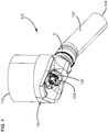
FIG. 1 is a perspective view of a first example dosing and mixing assembly including a conduit arrangement defining a mixing zone, an impact zone, and a merge zone in accordance with the principles of the present disclosure; -
FIG. 2 is a longitudinal cross-sectional view of the dosing and mixing assembly ofFIG. 1 ; -
FIG. 3 is an enlarged view of a portion of the dosing and mixing assembly ofFIG. 2 ; -
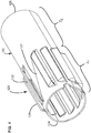
FIG. 4 is a first perspective view of an example first conduit suitable for use with the conduit arrangement of the dosing and mixing assembly ofFIG. 1 ; -
FIG. 5 is a second perspective view of the first conduit ofFIG. 4 ; -
FIG. 6 is a perspective view of an example second conduit suitable for use with the dosing and mixing assembly ofFIG. 1 ; -
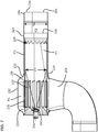
FIG. 7 is a perspective view of a second example dosing and mixing assembly including a conduit arrangement defining a mixing zone, an impact zone, and a merge zone in accordance with the principles of the present disclosure; -
FIG. 8 is a perspective view of at least part of the conduit arrangement ofFIG. 7 aligned with a treatment substrate; -
FIG. 9 is a first perspective view of an example first conduit suitable for use with the conduit arrangement of the dosing and mixing assembly ofFIG. 7 ; -
FIG. 10 is a second perspective view of the first conduit ofFIG. 9 ; -
FIG. 11 is a longitudinal cross-sectional view of the conduit arrangement ofFIG. 8 ; -
FIG. 12 is an enlarged view of a portion of the conduit arrangement ofFIG. 11 ; -
FIG. 13 is a longitudinal cross-sectional view of the three zones of an example conduit arrangement; -
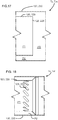
FIGS. 14-16 are longitudinal cross-sectional views showing example first transition regions between the mixing zone and the impact zone suitable for use with the conduit arrangement shown inFIG. 13 ; -
FIGS. 17-20 are longitudinal cross-sectional views showing example second transition regions between the impact zone and the merge zone suitable for use with the conduit arrangement shown inFIG. 13 ; and -
FIG. 21 is the enlarged view ofFIG. 12 with the local exhaust flow path lines illustrated. - Reference will now be made in detail to exemplary aspects of the present disclosure that are illustrated in the accompanying drawings. Wherever possible, the same reference numbers will be used throughout the drawings to refer to the same or like parts.
- The present disclosure is directed to a dosing and
mixing assembly 100, 200 at which reactant is mixed with exhaust flow within an exhaust aftertreatment device. For convenience within this disclosure, reference numbers in the 100's refer to components of the dosing and mixingassembly 100 and reference numbers in the 200's refer to components of the dosing and mixing assembly 200. The dosing andmixing assembly 100, 200 includes aconduit arrangement inlet outlet assembly 100, 200 at theinlet conduit arrangement outlet - The dosing and
mixing assembly 100, 200 includes a doser mounting location at which adoser mixing assembly 100, 200. Thedoser 145, 245 (also referred to as reactant injector) is configured to inject reactant (e.g., urea) into the exhaust flowing through theconduit arrangement assembly outlet assembly 100, 200. - In certain implementations, another
treatment substrate 108 may be disposed upstream of theconduit arrangement 110, 210 (seeFIG. 2 ). In various implementations, theupstream treatment substrate 108 can be a diesel particulate filter (DPF), a diesel oxidation catalyst (DOC), a close coupled SCR, or Lean NOx Trap. In certain implementations, both a DPF and a DOC are disposed upstream of thedosing conduit arrangement upstream substrates 108 may be coupled to theinlet conduit arrangement - The
conduit arrangement conduit arrangement first entrance inlet second entrance first entrance outlet - A first portion of the exhaust passing through the
inlet first entrance first entrance second entrance doser mounting location outlet - In certain implementations, the first portion of the exhaust includes a majority of the exhaust entering the
inlet inlet inlet inlet inlet inlet - In certain implementations, the second portion of the exhaust includes a minority of the exhaust entering the
inlet inlet inlet inlet inlet inlet - The
conduit arrangement first conduit - The
doser mounting location first conduit first conduit assembly 100 is configured to retain heat at this surface to inhibit reactant buildup as will be described herein. The more heat that can be added to this liquid film, the faster this liquid film will evaporate and mix with the exhaust. Thefirst conduit second conduit - For the sake of convenience and ease of understanding, this disclosure refers to the mixing zone PI, the impact zone P2, and the merge zone P3 as three separate zones. However, it will be understood by one of skill in the art that actions need not be fully confined to specific zones. For example, the turbulence applied to the exhaust within the first flow path P1 is initiated in the mixing zone P1, but may continue within the impact zone P2 and/or the merge zone P3. As another example, while a majority of the reactant impacts the
conduit arrangement conduit arrangement - In certain implementations, the conduit arrangement includes a
first conduit second conduit first conduit second conduits second conduit first conduit conduits first conduit second conduits - In certain examples, the second flow path P2 has a cross-sectional area that is smaller than a cross-sectional area of the first flow path P1. For example, the second flow path P2 may have a cross-sectional area that is 5-70% of the cross-sectional area of the first flow path P1. In certain examples, the cross-sectional area of the second flow path P2 is 10-65% of the cross-sectional area of the first flow path P1. In certain examples, the cross-sectional area of the second flow path P2 is 5-50% of the cross-sectional area of the first flow path P1. In certain examples, the cross-sectional area of the second flow path P2 is 5-35% of the cross-sectional area of the first flow path P1.
- In certain implementations, the
first conduit mixer first end first conduit mixer first conduit mixer louvered openings first conduit louvered openings first conduit first end first conduit louvered openings entrance first conduit louvered openings louvered openings mixer - The mixing zone P1 is configured so that the intensity of the turbulence (e.g., swirling) induced within the
first conduit 
- In certain implementations, the turbulence intensity for the exhaust traveling along the first flow path is at least 15%. In certain implementations, the turbulence intensity for the exhaust traveling along the first flow path ranges between 30% and 5%, decreasing along the flow direction. In certain implementations, the turbulence intensity for the exhaust traveling along the first flow path ranges between 25% and 15%, decreasing along the flow direction. In certain implementations, the turbulence intensity for the exhaust traveling along the first flow path ranges between 20% and 10%, decreasing along the flow direction. In certain implementations, the turbulence intensity for the exhaust traveling along the first flow path ranges between 3% and 20%, decreasing along the flow direction.
- In certain implementations, the turbulence intensity for the exhaust traveling along the second flow path is at least 5%. In certain implementations, the turbulence intensity for the exhaust traveling along the second flow path is no more than 20%. In certain implementations, the turbulence intensity for the exhaust traveling along the second flow path ranges between 20% and 5%, decreasing along the flow direction. In certain implementations, the turbulence intensity for the exhaust traveling along the second flow path ranges between 20% and 10%, decreasing along the flow direction. In certain implementations, the turbulence intensity for the exhaust traveling along the first flow path ranges between 15% and 5%, decreasing along the flow direction.
- In the example shown, the
first conduit circumferential section 127, 227 (i.e., a section in which the adjacentlouvered openings louvered openings 129, 229). For example, thenon-louvered section inlet upstream substrate 108 to guide the exhaust around the mixer input flow path P4, thereby evening out the distribution of the exhaust at thelouvered openings louvered opening - In some implementations, the
first conduit first conduit first conduit first conduit first conduit - In some implementations, the
second conduit second conduit second conduit conduit second conduits - In certain implementations, the
doser mounting location axial end first conduit doser mounting location doser first conduit second entrance second conduit conduits first conduit - In certain implementations, the
first conduit first conduit first conduit - Heating the
first conduit first conduit first conduit conduit arrangement first conduit - In certain implementations, the
conduit arrangement 110 also includes ahousing first conduit housing mixer first conduit housing louvered openings first conduit 120, 220 (seeFIGS. 3 and7 ). In certain examples, thehousing doser mounting location axial end first conduit housing doser mounting location axial end first conduit housing doser mounting location first conduit housing - In certain implementations, the
housing second conduit axial end second conduit housing second conduit housing upstream substrate 108. In other implementations, thehousing upstream substrate 108. - Referring now to
FIGS. 1-6 , a first example dosing and mixingassembly 100 is shown. In the first dosing and mixingassembly 100, thesecond conduit 130 includes a generally tubular body extending between the first and second axial ends 134, 136. In the example shown, the tubular body has a generally constant cross-dimension. In certain implementations, thesecond conduit 130 includesdimples 138, tabs, or other such features that help to align thesecond conduit 130 with thefirst conduit 120. In certain examples, thedimples 138 extend radially inwardly and contact thefirst conduit 120. In certain examples, thedimples 138 are secured to the first conduit 120 (e.g., by welding) to hold thesecond conduit 130 axially and rotationally fixed relative to thefirst conduit 120. - A third entrance to the third flow path P3 is defined at the merge zone P3. In the example shown, the second
axial end 126 of thefirst conduit 120 extends past the secondaxial end 136 of thesecond conduit 130 and the third entrance is defined at the secondaxial end 126 of thefirst conduit 120. The second portion of the exhaust flowing through the second flow path P2 merges with the first portion of the exhaust flowing through the first flow path P1 when the second portion passes the secondaxial end 126 of thefirst conduit 120. In certain implementations, theconduit arrangement 110 includes athird conduit 150 that defines the merge zone P3. - In certain implementations, insulation can be disposed about at least some of the
conduit arrangement 110 to inhibit heat dissipation. Maintaining the heated temperature within the conduit arrangement inhibits reactant deposit formation within theconduit arrangement 110. In certain implementations, the insulation is disposed about theconduit arrangement 110 at the impact zone P2. In certain implementations, the insulation is disposed about theconduit arrangement 110 at the impact zone P2 and the merge zone P3. In certain examples, the mixing zone P1 also may be insulated. - The
third conduit 150 is mounted to thesecond conduit 130. For example, thethird conduit 150 can be secured to thesecond conduit 130 using a clamp C or other fastener. In certain examples, thethird conduit 150 is mounted to thesecond conduit 130 at a coupling location that is radially aligned with thefirst conduit 120. In certain examples, the coupling location is radially aligned with the impact zone P2 of thefirst conduit 120. In certain implementations, the insulation is reduced or absent at the location of the clamp C. However, the heated exhaust traveling through the second flow path P2 insulates the impact zone P2 from the external environment at the coupling location. For example, the heated exhaust in the second flow path P2 flows between the clamp C or other fastener-which may otherwise dissipate heat at the coupling location-and thefirst conduit 120 at the impact zone P2. - Referring to
FIGS. 7-13 , a second example dosing and mixing assembly 200 is shown. In the second dosing and mixing assembly 200, thesecond conduit 230 includes a generally tubular body extending between the first and second axial ends 234, 236. In the example shown, the tubular body has a generally constant cross-dimension. In some implementations, thesecond conduit 230 mounts to thehousing 212. In other implementations, thesecond conduit 230 is integrally formed with thehousing 212. The secondaxial end 236 of thesecond conduit 230 extends past the secondaxial end 226 of thefirst conduit 220 along the conduit axis L. - In certain implementations, the
first conduit 220 defines the mixing zone PI, the impact zone P2, and at least a portion of the mixing zone P3. Thefirst conduit 220 defines the mixing zone P1 at themixer 228. For example, themixer first conduit 220 defines the impact zone P2 between the mixing zone P1 and the merge zone P3. In certain examples, the merge zone P3 is also partially defined by thesecond conduit 230 extending beyond thefirst conduit 220. - The
first conduit 220 has a first cross-dimension (e.g., diameter) H1 at the impact zone P2 that is smaller than a second cross-dimension H2 of thesecond conduit 230. The difference between the cross-dimensions HI, H2 provides the second flow passage P2. Thefirst conduit 220 has anenlarged section 223 at the secondaxial end 226. Theenlarged section 223 extends radially outwardly to thesecond conduit 230, thereby cutting off the second flow path P2 at the secondaxial end 226 of thefirst conduit 220. For example, an outer periphery of theenlarged section 223 contacts an inner surface of thesecond conduit 230. - At the merge zone P3, a third entrance is provided to the third flow path P3 from the first and second flow paths PI, P2. In the example shown, the
first conduit 220 defines one ormore apertures 225 that define the third entrance. The one ormore apertures 225 extend between the first and second flow paths PI, P2. Accordingly, exhaust flowing through the second flow path P2 passes through the one ormore apertures 225 to enter thefirst conduit 220 and joins with the exhaust flowing through the first flow path P1. In certain implementations,multiple apertures 225 extend along a circumference of thefirst conduit 220. In an example, theapertures 225 are circumferentially aligned in a ring. In other examples, theapertures 225 may form multiple rings. In other examples, theapertures 225 are not circumferentially aligned. - When the second portion of the exhaust passes into the
first conduit 220 through theapertures 225 from the second flow path PP2, the second portion of the exhaust is mixed with the first portion of the exhaust. Accordingly, the second portion of the exhaust is entrained into the mixing (e.g., swirling) flow of the first portion of the exhaust at the merge zone P3. Accordingly, the merged exhaust also may flow in the turbulent pattern (e.g., a swirl). The mixing exhaust flows through the common flow path P3 to theoutlet 204. In certain examples, the common flow path P3 is defined by the portion of thefirst conduit 220 defining theapertures 225, theenlarged portion 223 of thefirst conduit 220, and the portion of thesecond conduit 230 that extends beyond the secondaxial end 226 of thefirst conduit 220. In certain implementations, theoutlet 204 leads to a treatment substrate 206 (e.g., a catalytic treatment substrate). - Referring to
FIG. 12 , in certain implementations, eachaperture 225 is elongate along a slot axis S. In certain implementations, eachaperture 225 has a pair ofstraight edges 225a connected byends 225b. The slot axis S extends between theends 225b. In certain examples, thestraight edges 225a are at least twice as long as theends 225b. In certain examples, theends 225b are curved. In certain examples, eachaperture 225 has an oblong profile. In certain implementations, theapertures 225 are oriented and spaced so thatadjacent apertures 225 overlap (e.g., portions of thestraight edges 225a of theadjacent apertures 225 overlap) when viewed along a reference axis N extending perpendicular to the slot axis S. - Each
aperture 225 is oriented so that the slot axis S is angled relative to the conduit axis L. In certain implementations, an angle θ between the slot axis S and the conduit axis L is between about 5 degrees and about 85 degrees. In certain implementations, the angle θ is between about 25 degrees and about 75 degrees. In certain implementations, the angle θ is between about 30 degrees and about 60 degrees. In certain implementations, the angle θ is between about 40 degrees and about 50 degrees. In an example, the angle θ is about 45 degrees. - Referring to
FIG. 21 , in certain implementations, exhaust flows past theapertures 225 in a turbulent pattern so that local flow path lines F of the exhaust passing theapertures 225 are not coaxial with the conduit axis L. In certain examples, the exhaust passing theapertures 225 is moving in a swirling pattern. In certain implementations, the local flow path lines F of the exhaust passing theapertures 225 extend at an angle β relative to the conduit axis L. In certain implementations, an angle β between the local flow path lines F and the conduit axis L is between about 5 degrees and about 85 degrees. In certain implementations, the angle β is between about 25 degrees and about 75 degrees. In certain implementations, the angle β is between about 30 degrees and about 60 degrees. In certain implementations, the angle β is between about 40 degrees and about 50 degrees. In an example, the angle β is about 45 degrees. - The local flow path lines F of the exhaust near the
apertures 225 in the conduit wall extend at a second angle α relative to the slot axes S. In an implementation, the local flow path lines F of the exhaust near the conduit wall defining theapertures 225 extend at an angle α of about 90 degrees. In certain implementations, the angle α is between about 80 degrees and about 100 degrees. In other implementations, the angle α is between about 60 degrees and about 120 degrees. In certain implementations, the local flow path lines F extend at angles α relative to the slot axes S of between about 30 degrees and about 150 degrees. In certain implementations, the angle α is between about 45 degrees and about 135 degrees. - Referring to
FIGS. 12 and21 , a liquid film of reactant deposited on the inner surface of thefirst conduit 220 at or near the impact zone P2 is pushed along the conduit wall towards one of theapertures 225. In certain implementations, theapertures 225 are oriented so that the exhaust passes generally transversely over elongate sides of theapertures 225. For example, the deposited liquid film may be guided (e.g., pushed) towards the upstreamstraight edge 225a of eachaperture 225. In certain examples, the deposited liquid film also may be guided towards the downstreamstraight edges 225a of eachaperture 225. When theapertures 225 are oriented transverse to the local flow path lines F and spaced to overlap each other, any deposited reactant propelled by the exhaust will encounter one of theapertures 225. - In certain examples, a liquid film of reactant will accumulate at the
straight edges 225a of theapertures 225. In certain examples, when sufficient reactant accumulates into a droplet, the droplet will be entrained by the mixing (e.g., swirling) flow of exhaust. For example, the exhaust passing through theapertures 225 from the second flow path P2 may blow the droplet into the common flow path P3. Accordingly, the exhaust will remove the droplet of reactant from the inner surface of thefirst conduit 220 to reintroduce the reactant into the exhaust flow. The reintroduced reactant will mix with the exhaust as the exhaust and reactant travel down the combined flow path P3. - Referring to
FIG. 13 , a conduit arrangement, such asconduit arrangement -
FIGS. 14-16 illustrate various example first transition regions T1 andFIGS. 17-20 illustrate various example second transition regions T2 suitable for use in any of theconduit arrangements FIG. 14 shows an example first transition region T1A in which thesecond entrance axial end second conduit first conduit axial end first conduit axial end first conduit -
FIGS. 15 and16 show other example first transition regions T1B, T1C in which thesecond entrance axial end second conduit second entrance second conduit FIG. 15 , thefirst conduit second conduit FIG. 16 , thesecond conduit first conduit -
FIG. 17 shows an example second transition region T2A in which the third entrance to the third flow path P3 is defined by an open secondaxial end first conduit second conduit second conduit axial conduit axial end first conduit axial end first conduit -
FIGS. 18-20 show other example second transition regions T2B, T2C, T2D in which the third entrance to the third flow path P3 is downstream from the secondaxial end first conduit more apertures 125, 225 defined in thefirst conduit - In the second transition region T2B shown in
FIG. 18 , the secondaxial end first conduit 120 tapers radially outward to thesecond conduit apertures 125, 225. In other examples, theapertures 125, 225 can be provided along the radially tapering portion of thefirst conduit second end first conduit axial end first conduit axial end second conduit second conduit - In the second transition region T2C shown in
FIG. 19 , the secondaxial end first conduit 120 tapers radially outward to thesecond conduit FIG. 18 . Thefirst conduit apertures 125, 225 upstream of the radial taper. Unlike inFIG. 18 , however, thefirst conduit FIG. 19 is defined by thefirst conduit first conduit apertures 125, 225 and defines the third flow path P3 downstream of theapertures 125, 225. - In the second transition region T2D shown in
FIG. 20 , the secondaxial end second conduit first conduit axial end second conduit first conduit apertures 125, 225 through which exhaust flows from the second flow path P2 to the third flow path P3. Thefirst conduit apertures 125, 225 and defines the third flow path P3 downstream of theapertures 125, 225. - Specific combinations of features that represent embodiments of the invention disclosed herein, are described by the following numbered clauses:
- 1. A conduit arrangement (110, 210) for use in an exhaust aftertreatment assembly, the conduit arrangement extending along a conduit axis and comprising:
- a first flow path (P1) extending along the conduit axis (L) of the conduit arrangement (110, 210), the first flow path (P1) having a first entrance (122, 222);
- a second flow path (P2) at least partially surrounding the first flow path (P1), the second flow path (P2) having a second entrance (132, 232) that is located downstream from the first entrance (122, 222), the second flow path (P2) having a cross-sectional area that is smaller than a cross-sectional area of the first flow path (P1);
- a common flow (P3) path being fed from both the first flow path (P1) and the second flow path (P2);
- a mixing zone (P1) at which turbulence is applied to exhaust flowing through the first flow path (P1) such that the turbulence within the first flow path (P1) is greater than any turbulence within the second flow path (P2);
- an impact zone (P2) downstream of the mixing zone and upstream of the common flow path (P3), the impact zone (P2) defined within the first flow path (P1);
- a merge zone (P3) at which the first and second flow paths (P1, P2) combine to form the common flow path (P3), the merge zone (P3) being downstream of the impact zone (P2); and
- a doser mounting location (140, 240) configured to receive a reactant injector (145, 245), the doser mounting location (140, 240) being oriented to face into the first flow path (P1) at or upstream of the mixing zone (P1).
- 2. The conduit arrangement (110, 210) of clause 1, further comprising a first conduit (120, 220) extending between first and second axial ends (124, 126; 224, 226) and defining a through-passage, the through-passage forming the first flow path (P1), the first conduit (120, 220) defining the mixing zone (P1) and the impact zone (P2), the first conduit (120, 220) including tangential velocity imparting members disposed at the mixing zone (P2).
- 3. The conduit arrangement (110, 210) of clause 2, wherein the doser mounting location (140, 240) is disposed at the first axial (124, 224) end of the first conduit (120, 220) and is oriented to face along the conduit axis (L) of the conduit arrangement (110, 210).
- 4. The conduit arrangement (110, 210) of any of clauses 2-3, wherein the tangential velocity imparting members include louvered apertures (129, 229).
- 5. The conduit arrangement (110, 210) of any of clauses 2-4, further comprising a second conduit (130, 230) disposed at least partially around the first conduit (120, 220) to define the second flow path (P2) therebetween, the second conduit (130, 230) extending between respective first and second axial ends (134, 234; 136, 236), the first axial end (134, 234) of the second conduit (130, 230) being offset downstream from the first axial end (124, 224) of the first conduit (120, 220).
- 6. The conduit arrangement (110, 210) of clause 5, wherein the second conduit (130, 230) defines a constant cross-dimension around the impact zone (P2).
- 7. The conduit arrangement (110, 210) of clause 5, wherein the second conduit (130, 230) defines a profiled surface around the impact zone (P2).
- 8. The conduit arrangement (110, 210) of any of clauses 5-7, wherein the first axial end (134, 234) of the second conduit (130, 230) is open to define the second entrance (132, 232) to the second flow path (P2).
- 9. The conduit arrangement (110, 210) of any of clauses 5-7, wherein the second conduit (130, 230) defines one or more apertures (135, 235) downstream of the first axial end (134, 234) of the second conduit (130, 230), the one or more apertures (135, 235) of the second conduit (130, 230) defining the second entrance (132, 232) to the second flow path (P2).
- 10. The conduit arrangement (110, 210) of clause 9, wherein the second conduit (130, 230) extends radially outward away from the first conduit (120, 220) at the first axial end (134, 234) of the second conduit (130, 230).
- 11. The conduit arrangement (110, 210) of clause 9, wherein the first conduit (120, 220) extends radially inward away from the second conduit (130, 230) at the first axial end (134, 234) of the second conduit (130, 230).
- 12. The conduit arrangement (110, 210) of any of clauses 5-11, wherein the second axial end (126) of the first conduit (120) does not contact the second conduit (130) at the merge zone (P3).
- 13. The conduit arrangement (210) of any of clauses 5-11, wherein the first conduit (220) defines one or more apertures (225) that define an entrance to the common flow path (P3) at the merge zone (P3).
- 14. The conduit arrangement (210) of clause 13, wherein the first conduit (220) tapers radially outward to contact the second conduit (230) at or upstream of the one or more apertures (225) of the first conduit.
- 15. The conduit arrangement (210) of clause 13, wherein the second conduit (230) tapers radially inward to contact the first conduit (220) at or upstream of the one or more apertures (225) of the first conduit (220).
- 16. The conduit arrangement (110, 210) of any of clauses 13-15, wherein the common flow path (P3) is defined by the first conduit (120, 220).
- 17. The conduit arrangement (110, 210) of any of clauses 13-15, wherein the common flow path (P3) is defined by the second conduit (130, 230).
- 18. The conduit arrangement (110) of any of clauses 13-15, wherein the common flow path (P3) is defined by a third conduit (150) coupled to either of the first and second conduits (120; 230).
- 19. The conduit arrangement (210) of any of clauses 13-18, wherein the one or more apertures (225) of the first conduit (220) are elongate along slot axes (S), and wherein the one or more apertures (225) of the first conduit (220) are oriented so that the slot axes (S) are angled between 5 degrees and 85 degrees relative to the conduit axis (L) of the conduit arrangement (210).
- 20. The conduit arrangement of clause 19, wherein the one or more apertures (225) of the first conduit (220) are oriented and spaced so that the one or more apertures (225) of the first conduit overlap when viewed along a reference axis (N) extending perpendicular to any of the slot axes (S).
- 21. The conduit arrangement of clauses 13-20, wherein the one or more apertures (225) of the first conduit (220) are disposed in a ring extending around a circumference of the first conduit (220).
- 22. A mixing assembly (100, 200) for use in an exhaust aftertreatment assembly, the mixing assembly (100, 200) comprising:
- a first conduit (120, 220) extending along a conduit axis (L) from a first axial end (124, 224) to a second axial end (126, 226) to form a main flow path, the first conduit (120, 220) defining a bypass exit at the second axial end (126, 226), the first conduit (120, 220) also defining an impact region (P2) disposed between the first axial end (124, 224) and the bypass exit, the first conduit (120, 220) defining a continuous surface at the impact region (P2);
- a swirl mixer (128, 228) disposed at the first end (124, 224) of the first conduit (120, 220), the swirl mixer (128, 228) being configured to induce swirling of exhaust flowing through the first conduit (120, 220);
- a doser mounting location (140, 240) at the first axial end (124, 224) of the first conduit (120, 220), the doser mounting location (140, 240) being positioned to orient a doser (145, 245) mounted thereto to dispense a reactant along a spray path (R) intersecting the impact region (P2) of the first conduit (120, 220); and
- a second conduit (130, 230) surrounding at least a segment of the first conduit (120, 220) to form a bypass flow path between the first and second conduits (120, 220; 130, 230), the second conduit (130, 230) being coaxial with the first conduit (120, 220), the second conduit (130, 230) having a first axial (134, 234) end located downstream of the first axial end (124, 224) of the first conduit (120, 220) to form a bypass entrance downstream of the swirl mixer (128, 228),
- wherein the bypass exit provides fluid communication between the bypass flow path and the main flow path to allow exhaust flowing through the bypass flow path to rejoin with exhaust flowing through the main flow path.
- 23. The mixing assembly (100, 200) of
clause 22, wherein the swirl mixer (128, 228) includes a louvered section (129, 229) of the first conduit (120, 220). - 24. The mixing assembly (100, 200) of any of
clauses 22 and 23, wherein the second conduit (130, 230) has a profiled shape. - 25. The mixing assembly (100, 200) of any of clauses 22-24, wherein the bypass exit includes a plurality of apertures (225) disposed circumferentially around the first conduit (120, 220).
- 26. The mixing assembly (100, 200) of clause 25, wherein each of the apertures (225) is elongated along a slot axis that is non-orthogonally angled relative to the conduit axis.
- 27. The mixing assembly (100, 200) of clause 26, wherein one of the apertures (225) overlaps an adjacent aperture (225) when viewed along a reference axis normal to the slot axis of the one of the apertures (225).
- 28. The mixing assembly (100, 200) of any of clauses 22-24, wherein the bypass exit is defined by the second axial end (126, 226) of the first conduit (120, 220) terminating downstream of a second axial end (136, 236) of the second conduit (130, 230).
- 29. The mixing assembly (100, 200) of any of clauses 22-28, wherein the bypass entrance is defined through one or more apertures defined in the second conduit (130, 230).
- 30. The mixing assembly (100, 200) of any of clauses 22-28, wherein the bypass entrance is defined by a radial gap between the first conduit (120, 200) and the first axial end (134, 234) of the second conduit (130, 230).
- 31. A method of treating exhaust comprising:
- directing exhaust along a conduit axis (L) of a conduit arrangement (110,210);
- guiding a first portion of the exhaust through an entrance (122, 222) to a first flow path (P1) of the conduit arrangement (110, 210);
- inducing swirling of the first portion of the exhaust at a mixing zone (P1) of the first flow path (P1);
- injecting reactant into the first portion of the exhaust traveling along a conduit (120, 220) that defines at least an impact zone (P2) of the first flow path (P1), the impact zone (P2) being downstream from the mixing zone (P1), the reactant being injected along a spray path (R) that intersects the conduit (120, 220) at the impact zone (P2);
- guiding a second portion of the exhaust to bypass the entrance (122, 222) to the first flow path (P1) and to instead enter a second flow (P2) path upstream of the entrance (122, 222) to the first flow path (P1), the second flow path (P2) surrounding the conduit (120, 220) or at least at the impact zone (P2) of the conduit (120, 220); and
- merging the first and second portions of the exhaust downstream of the impact zone (P2).
- 32. The method of clause 31, wherein merging the first and second portions of the exhaust includes guiding the second portion of the exhaust from the second flow path (P2) inwardly through a plurality of apertures defined by the conduit.
- 33. The method of clause 32, wherein the apertures are elongate along slot axes; and wherein the apertures are oriented so that the slot axes are transverse to flow axes of the first portion of the exhaust along an interior surface of the conduit.
- 34. The method of clause 33, wherein the merged first and second portions of the exhaust are swirling at the apertures so that the flow axes are angled relative to the conduit axis of the conduit arrangement.
- 35. The method of clause 33, wherein the apertures are spaced to overlap along reference axes that are transverse to the slot axes so that each flow axis intersects at least one of the apertures.
- Having described the preferred aspects and implementations of the present disclosure, modifications and equivalents of the disclosed concepts may readily occur to one skilled in the art. However, it is intended that such modifications and equivalents be included within the scope of the claims which are appended hereto.
Claims (16)
- A conduit arrangement (110, 210) for use in an exhaust aftertreatment assembly, the conduit arrangement extending along a conduit axis and comprising:a first flow path (P1) extending along the conduit axis (L) of the conduit arrangement (110, 210), the first flow path (P1) having a first entrance (122, 222);a second flow path (P2) at least partially surrounding the first flow path (P1), the second flow path (P2) having a second entrance (132, 232) that is located downstream from the first entrance (122, 222), the second flow path (P2) having a cross-sectional area that is smaller than a cross-sectional area of the first flow path (P1);a common flow (P3) path being fed from both the first flow path (P1) and the second flow path (P2);a mixing zone (P1) at which turbulence is applied to exhaust flowing through the first flow path (P1) such that the turbulence within the first flow path (P1) is greater than any turbulence within the second flow path (P2);an impact zone (P2) downstream of the mixing zone and upstream of the common flow path (P3), the impact zone (P2) defined within the first flow path (P1);a merge zone (P3) at which the first and second flow paths (P1, P2) combine to form the common flow path (P3), the merge zone (P3) being downstream of the impact zone (P2); anda doser mounting location (140, 240) configured to receive a reactant injector (145, 245), the doser mounting location (140, 240) being oriented to face into the first flow path (P1) at or upstream of the mixing zone (P1).
- The conduit arrangement (110, 210) of claim 1, further comprising a first conduit (120, 220) extending between first and second axial ends (124, 126; 224, 226) and defining a through-passage, the through-passage forming the first flow path (P1), the first conduit (120, 220) defining the mixing zone (P1) and the impact zone (P2), the first conduit (120, 220) including tangential velocity imparting members disposed at the mixing zone (P2).
- The conduit arrangement (110, 210) of claim 2, wherein the doser mounting location (140, 240) is disposed at the first axial (124, 224) end of the first conduit (120, 220) and is oriented to face along the conduit axis (L) of the conduit arrangement (110, 210).
- The conduit arrangement (110, 210) of any of claims 2-3, wherein the tangential velocity imparting members include louvered apertures (129, 229).
- The conduit arrangement (110, 210) of any of claims 2-4, further comprising a second conduit (130, 230) disposed at least partially around the first conduit (120, 220) to define the second flow path (P2) therebetween, the second conduit (130, 230) extending between respective first and second axial ends (134, 234; 136, 236), the first axial end (134, 234) of the second conduit (130, 230) being offset downstream from the first axial end (124, 224) of the first conduit (120, 220).
- The conduit arrangement (110, 210) of claim 5, wherein the second conduit (130, 230) defines a constant cross-dimension around the impact zone (P2).
- The conduit arrangement (110, 210) of claim 5, wherein the second conduit (130, 230) defines a profiled surface around the impact zone (P2).
- The conduit arrangement (110, 210) of any of claims 5-7, wherein the first axial end (134, 234) of the second conduit (130, 230) is open to define the second entrance (132, 232) to the second flow path (P2).
- The conduit arrangement (110, 210) of any of claims 5-7, wherein the second conduit (130, 230) defines one or more apertures (135, 235) downstream of the first axial end (134, 234) of the second conduit (130, 230), the one or more apertures (135, 235) of the second conduit (130, 230) defining the second entrance (132, 232) to the second flow path (P2).
- The conduit arrangement (110, 210) of claim 9, wherein the second conduit (130, 230) extends radially outward away from the first conduit (120, 220) at the first axial end (134, 234) of the second conduit (130, 230).
- The conduit arrangement (110, 210) of claim 9, wherein the first conduit (120, 220) extends radially inward away from the second conduit (130, 230) at the first axial end (134, 234) of the second conduit (130, 230).
- The conduit arrangement (110) of any of claims 5-11, wherein the second axial end (126) of the first conduit (120) does not contact the second conduit (130) at the merge zone (P3).
- The conduit arrangement (210) of any of claims 5-11, wherein the first conduit (220) defines one or more apertures (225) that define an entrance to the common flow path (P3) at the merge zone (P3).
- The conduit arrangement (210) of claim 13, wherein the first conduit (220) tapers radially outward to contact the second conduit (230) at or upstream of the one or more apertures (225) of the first conduit.
- The conduit arrangement (210) of claim 13, wherein the second conduit (230) tapers radially inward to contact the first conduit (220) at or upstream of the one or more apertures (225) of the first conduit (220).
- A method of treating exhaust comprising:directing exhaust along a conduit axis (L) of a conduit arrangement (110, 210);guiding a first portion of the exhaust through an entrance (122, 222) to a first flow path (P1) of the conduit arrangement (110, 210);inducing swirling of the first portion of the exhaust at a mixing zone (P1) of the first flow path (P1);injecting reactant into the first portion of the exhaust traveling along a conduit (120, 220) that defines at least an impact zone (P2) of the first flow path (P1), the impact zone (P2) being downstream from the mixing zone (P1), the reactant being injected along a spray path (R) that intersects the conduit (120, 220) at the impact zone (P2);guiding a second portion of the exhaust to bypass the entrance (122, 222) to the first flow path (P1) and to instead enter a second flow (P2) path upstream of the entrance (122, 222) to the first flow path (P1), the second flow path (P2) surrounding the conduit (120, 220) or at least at the impact zone (P2) of the conduit (120, 220); andmerging the first and second portions of the exhaust downstream of the impact zone (P2).
Priority Applications (5)
| Application Number | Priority Date | Filing Date | Title |
|---|---|---|---|
| EP19197416.1A EP3792462A1 (en) | 2019-09-13 | 2019-09-13 | Dosing and mixing assemblies for exhaust aftertreatment system |
| EP20767889.7A EP4028653A1 (en) | 2019-09-13 | 2020-06-30 | Dosing and mixing assemblies for exhaust aftertreatment system |
| PCT/US2020/040293 WO2021050157A1 (en) | 2019-09-13 | 2020-06-30 | Dosing and mixing assemblies for exhaust aftertreatment system |
| US17/642,620 US11773763B2 (en) | 2019-09-13 | 2020-06-30 | Dosing and mixing assemblies for exhaust aftertreatment system |
| US18/476,989 US12473851B2 (en) | 2019-09-13 | 2023-09-28 | Dosing and mixing assemblies for exhaust aftertreatment system |
Applications Claiming Priority (1)
| Application Number | Priority Date | Filing Date | Title |
|---|---|---|---|
| EP19197416.1A EP3792462A1 (en) | 2019-09-13 | 2019-09-13 | Dosing and mixing assemblies for exhaust aftertreatment system |
Publications (1)
| Publication Number | Publication Date |
|---|---|
| EP3792462A1 true EP3792462A1 (en) | 2021-03-17 |
Family
ID=67981892
Family Applications (2)
| Application Number | Title | Priority Date | Filing Date |
|---|---|---|---|
| EP19197416.1A Withdrawn EP3792462A1 (en) | 2019-09-13 | 2019-09-13 | Dosing and mixing assemblies for exhaust aftertreatment system |
| EP20767889.7A Pending EP4028653A1 (en) | 2019-09-13 | 2020-06-30 | Dosing and mixing assemblies for exhaust aftertreatment system |
Family Applications After (1)
| Application Number | Title | Priority Date | Filing Date |
|---|---|---|---|
| EP20767889.7A Pending EP4028653A1 (en) | 2019-09-13 | 2020-06-30 | Dosing and mixing assemblies for exhaust aftertreatment system |
Country Status (3)
| Country | Link |
|---|---|
| US (2) | US11773763B2 (en) |
| EP (2) | EP3792462A1 (en) |
| WO (1) | WO2021050157A1 (en) |
Families Citing this family (6)
| Publication number | Priority date | Publication date | Assignee | Title |
|---|---|---|---|---|
| EP3760846A1 (en) | 2019-07-04 | 2021-01-06 | Donaldson Company, Inc. | System for mixing a liquid spray into a gaseous flow and exhaust aftertreatment device comprising same |
| CN114542248B (en) * | 2022-01-18 | 2023-06-23 | 潍柴动力股份有限公司 | SCR system and engine |
| DE102022104314A1 (en) | 2022-02-23 | 2023-08-24 | Friedrich Boysen GmbH & Co KG. | Device for mixing an additive with a gas stream |
| EP4239169A1 (en) | 2022-03-03 | 2023-09-06 | Donaldson Company, Inc. | Mixing tubes and exhaust aftertreatment systems with improved urea water solution mixing properties |
| CN119604670A (en) * | 2022-08-09 | 2025-03-11 | 康明斯排放处理公司 | Mixer for exhaust aftertreatment system |
| DE112023003669T5 (en) * | 2022-09-02 | 2025-06-18 | Cummins Emission Solutions Inc. | EXHAUST GAS AFTERTREATMENT SYSTEM INCLUDING A MIXER WITH INJECTOR CONE CROSS-REFERENCE TO RELATED APPLICATION |
Citations (5)
| Publication number | Priority date | Publication date | Assignee | Title |
|---|---|---|---|---|
| US20090255242A1 (en) * | 2008-04-09 | 2009-10-15 | Woodward Governor Company | Low Pressure Drop Mixer for Radial Mixing of Internal Combustion Engine Exhaust Flows, Combustor Incorporating Same, and Methods of Mixing |
| US20110061369A1 (en) * | 2009-09-15 | 2011-03-17 | Yetkin Dervis A | Burner for a Diesel Aftertreatment System |
| WO2012089290A1 (en) * | 2010-12-27 | 2012-07-05 | Friedrich Boysen Gmbh & Co. Kg | Device for distributing fluids in exhaust systems |
| DE102012010878A1 (en) * | 2012-06-01 | 2013-12-05 | Daimler Ag | Reductant addition and treatment system of a motor vehicle |
| US20160326931A1 (en) * | 2013-04-11 | 2016-11-10 | Perkins Engines Company Limited | Mixer and Emissions Cleaning Module |
Family Cites Families (59)
| Publication number | Priority date | Publication date | Assignee | Title |
|---|---|---|---|---|
| JP4928304B2 (en) | 2007-02-23 | 2012-05-09 | 日野自動車株式会社 | Exhaust purification device |
| DE102007028449A1 (en) | 2007-04-25 | 2008-10-30 | J. Eberspächer GmbH & Co. KG | Mixing and / or evaporating device and associated production method |
| DE102007019878A1 (en) | 2007-04-25 | 2008-11-06 | J. Eberspächer GmbH & Co. KG | Mixing and / or evaporating device and associated production method |
| DE202007010324U1 (en) | 2007-07-25 | 2008-11-27 | Heinrich Gillet Gmbh | Apparatus for aftertreating the exhaust gases of diesel engines |
| GB2452249A (en) | 2007-08-17 | 2009-03-04 | Emcon Technologies Germany | An exhaust system |
| US8079211B2 (en) | 2008-11-06 | 2011-12-20 | Ford Global Technologies, Llc | Bypass purge for protecting against formation of reductant deposits |
| DE102009014433A1 (en) | 2009-03-26 | 2010-09-30 | J. Eberspächer GmbH & Co. KG | Exhaust gas treatment device |
| DE102009024535A1 (en) | 2009-06-10 | 2010-12-16 | J. Eberspächer GmbH & Co. KG | exhaust aftertreatment device |
| DE102009034670A1 (en) | 2009-07-25 | 2011-01-27 | J. Eberspächer GmbH & Co. KG | Mixing and / or evaporation device |
| JP5566134B2 (en) * | 2010-03-05 | 2014-08-06 | 日野自動車株式会社 | Exhaust gas temperature increase combustor |
| EP3267005B2 (en) | 2010-06-22 | 2023-12-27 | Donaldson Company, Inc. | Exhaust aftertreatment device |
| DE102010032576A1 (en) | 2010-07-28 | 2012-02-02 | Emitec Gesellschaft Für Emissionstechnologie Mbh | Device for near-exhaust gas treatment |
| SE535219C2 (en) | 2010-10-06 | 2012-05-29 | Scania Cv Abp | Arrangement for introducing a liquid medium into exhaust gases from an internal combustion engine |
| FI20106317A0 (en) | 2010-12-14 | 2010-12-14 | Proventia Emission Control Oy | METHOD AND DEVICE FOR CLEANING THE EXHAUST GAS |
| JP5349575B2 (en) | 2011-12-27 | 2013-11-20 | 株式会社小松製作所 | Reducing agent aqueous solution mixing device and exhaust gas aftertreatment device |
| US8932530B2 (en) | 2011-12-27 | 2015-01-13 | Komatsu Ltd. | Reducing agent aqueous solution mixing device and exhaust gas post-treatment device |
| US8916100B2 (en) | 2011-12-27 | 2014-12-23 | Komatsu Ltd. | Reducing agent aqueous solution mixing device and exhaust gas post-treatment device |
| JP5985822B2 (en) * | 2011-12-28 | 2016-09-06 | 日野自動車株式会社 | Exhaust purification device |
| US8800276B2 (en) | 2012-03-14 | 2014-08-12 | Ford Global Technologies, Llc | Mixing system |
| US9266075B2 (en) | 2012-09-28 | 2016-02-23 | Faurecia Emissions Control Technologies Usa, Llc | Doser and mixer for a vehicle exhaust system |
| DE102012218565B4 (en) | 2012-10-11 | 2015-07-16 | Eberspächer Exhaust Technology GmbH & Co. KG | Exhaust system with line element |
| DE202012011764U1 (en) | 2012-12-07 | 2013-01-30 | Eberspächer Catem Gmbh & Co. Kg | Mixer for aftertreatment of exhaust gases |
| US9289724B2 (en) | 2013-05-07 | 2016-03-22 | Tenneco Automotive Operating Company Inc. | Flow reversing exhaust gas mixer |
| US9364790B2 (en) | 2013-05-07 | 2016-06-14 | Tenneco Automotive Operating Company Inc. | Exhaust mixing assembly |
| FI125946B (en) | 2013-06-03 | 2016-04-29 | Proventia Emission Control Oy | Exhaust after-treatment device |
| DE102013210799C5 (en) | 2013-06-10 | 2020-07-09 | Eberspächer Exhaust Technology GmbH & Co. KG | Exhaust system of an internal combustion engine |
| WO2015012829A1 (en) | 2013-07-25 | 2015-01-29 | Faurecia Emissions Control Technologies, Usa, Llc | Mixer with swirl box for a vehicle exhaust system |
| US9410464B2 (en) | 2013-08-06 | 2016-08-09 | Tenneco Automotive Operating Company Inc. | Perforated mixing pipe with swirler |
| US10369533B2 (en) | 2013-09-13 | 2019-08-06 | Donaldson Company, Inc. | Dosing and mixing arrangement for use in exhaust aftertreatment |
| EP2865861B2 (en) | 2013-10-22 | 2019-05-15 | Eberspächer Exhaust Technology GmbH & Co. KG | Catalyst assembly with injection section |
| EP3498995B1 (en) * | 2014-01-31 | 2020-09-09 | Donaldson Company, Inc. | Dosing and mixing arrangement for use in exhaust aftertreatment |
| DE102014205158A1 (en) | 2014-03-19 | 2015-09-24 | Eberspächer Exhaust Technology GmbH & Co. KG | Mixer for an exhaust system |
| EP3152419B1 (en) | 2014-06-03 | 2020-03-04 | Faurecia Emissions Control Technologies, USA, LLC | Doser cone assembly |
| DE202014102872U1 (en) | 2014-06-10 | 2014-07-09 | Tenneco Gmbh | exhaust mixer |
| DE102014213746A1 (en) | 2014-07-15 | 2016-01-21 | Eberspächer Exhaust Technology GmbH & Co. KG | Static mixer |
| DE102014215083B4 (en) | 2014-07-31 | 2023-11-02 | Purem GmbH | Mixer and mixing device for an exhaust system |
| DE102014222296A1 (en) | 2014-10-31 | 2016-05-04 | Eberspächer Exhaust Technology GmbH & Co. KG | Exhaust gas treatment device |
| DE102014222698B4 (en) | 2014-11-06 | 2017-12-14 | Eberspächer Exhaust Technology GmbH & Co. KG | Exhaust after-treatment device with injection section |
| DE102014119671A1 (en) | 2014-12-29 | 2016-06-30 | Eberspächer Exhaust Technology GmbH & Co. KG | Mixer arrangement for an exhaust system of an internal combustion engine |
| US9784163B2 (en) | 2015-01-22 | 2017-10-10 | Tenneco Automotive Operating Company Inc. | Exhaust aftertreatment system having mixer assembly |
| DE102015002974A1 (en) | 2015-03-10 | 2016-09-15 | Man Truck & Bus Ag | Device for the aftertreatment of exhaust gas of a motor vehicle |
| WO2016158993A1 (en) * | 2015-03-30 | 2016-10-06 | いすゞ自動車株式会社 | Exhaust purification unit |
| JP2016205188A (en) * | 2015-04-20 | 2016-12-08 | いすゞ自動車株式会社 | Exhaust emission control unit |
| US9714598B2 (en) | 2015-04-30 | 2017-07-25 | Faurecia Emissions Control Technologies, Usa, Llc | Mixer with integrated doser cone |
| BR112017026777B1 (en) | 2015-06-12 | 2022-11-16 | Donaldson Company, Inc | EXHAUST TREATMENT DEVICE |
| DE102015110426A1 (en) | 2015-06-29 | 2016-12-29 | Eberspächer Exhaust Technology GmbH & Co. KG | Exhaust gas mixing system |
| FR3041691B1 (en) | 2015-09-29 | 2017-12-01 | Faurecia Systemes D'echappement | EXHAUST LINE WITH REAGENT INJECTOR |
| US9644516B1 (en) | 2015-10-16 | 2017-05-09 | Cummins Emission Solutions Inc. | Mounting plate for mounting injectors and directing reductant flow in exhaust conduits |
| DE102016104361A1 (en) | 2016-03-10 | 2017-09-14 | Eberspächer Exhaust Technology GmbH & Co. KG | mixer |
| US10428718B2 (en) | 2016-05-09 | 2019-10-01 | Tenneco Automotive Operating Company Inc. | Compact inline inlet with integrated cast ring |
| DE102017100246A1 (en) | 2016-11-14 | 2018-05-17 | Eberspächer Exhaust Technology GmbH & Co. KG | Reagent dispensing assembly |
| GB2557651B (en) * | 2016-12-14 | 2019-08-21 | Perkins Engines Co Ltd | Pipe mixer for an aftertreatment system |
| WO2018156146A1 (en) | 2017-02-24 | 2018-08-30 | Faurecia Emissions Control Technologies, Usa, Llc | Injector spray protector |
| EP3392480B1 (en) | 2017-04-21 | 2021-06-02 | Donaldson Company, Inc. | System for mixing a liquid spray into a gaseous flow and exhaust aftertreatment device comprising same |
| US10273853B2 (en) | 2017-09-29 | 2019-04-30 | Tenneco Automotive Operating Company Inc. | Wire mesh mixing tube |
| CN108397262A (en) | 2018-02-12 | 2018-08-14 | 无锡威孚力达催化净化器有限责任公司 | Light-duty diesel vehicle oblique cutting eddy flow mix aperture pipe post-processes encapsulating structure |
| EP3847351B1 (en) * | 2018-09-06 | 2024-02-28 | CNH Industrial Italia S.p.A. | Improved after treatment system for a vehicle |
| EP3760846A1 (en) | 2019-07-04 | 2021-01-06 | Donaldson Company, Inc. | System for mixing a liquid spray into a gaseous flow and exhaust aftertreatment device comprising same |
| EP3997314B1 (en) | 2019-07-11 | 2024-03-06 | Donaldson Company, Inc. | Dosing conduit arrangements for exhaust aftertreatment system |
-
2019
- 2019-09-13 EP EP19197416.1A patent/EP3792462A1/en not_active Withdrawn
-
2020
- 2020-06-30 US US17/642,620 patent/US11773763B2/en active Active
- 2020-06-30 WO PCT/US2020/040293 patent/WO2021050157A1/en not_active Ceased
- 2020-06-30 EP EP20767889.7A patent/EP4028653A1/en active Pending
-
2023
- 2023-09-28 US US18/476,989 patent/US12473851B2/en active Active
Patent Citations (5)
| Publication number | Priority date | Publication date | Assignee | Title |
|---|---|---|---|---|
| US20090255242A1 (en) * | 2008-04-09 | 2009-10-15 | Woodward Governor Company | Low Pressure Drop Mixer for Radial Mixing of Internal Combustion Engine Exhaust Flows, Combustor Incorporating Same, and Methods of Mixing |
| US20110061369A1 (en) * | 2009-09-15 | 2011-03-17 | Yetkin Dervis A | Burner for a Diesel Aftertreatment System |
| WO2012089290A1 (en) * | 2010-12-27 | 2012-07-05 | Friedrich Boysen Gmbh & Co. Kg | Device for distributing fluids in exhaust systems |
| DE102012010878A1 (en) * | 2012-06-01 | 2013-12-05 | Daimler Ag | Reductant addition and treatment system of a motor vehicle |
| US20160326931A1 (en) * | 2013-04-11 | 2016-11-10 | Perkins Engines Company Limited | Mixer and Emissions Cleaning Module |
Also Published As
| Publication number | Publication date |
|---|---|
| WO2021050157A1 (en) | 2021-03-18 |
| US20240018890A1 (en) | 2024-01-18 |
| US11773763B2 (en) | 2023-10-03 |
| EP4028653A1 (en) | 2022-07-20 |
| US20220341357A1 (en) | 2022-10-27 |
| US12473851B2 (en) | 2025-11-18 |
Similar Documents
| Publication | Publication Date | Title |
|---|---|---|
| US12473851B2 (en) | Dosing and mixing assemblies for exhaust aftertreatment system | |
| US10940451B2 (en) | Exhaust treatment device | |
| US10844764B2 (en) | Dosing and mixing arrangement for use in exhaust aftertreatment | |
| US10967329B2 (en) | Automotive exhaust aftertreatment system having a swirl-back mixer | |
| US8756921B2 (en) | Reductant delivery device | |
| EP3111062B1 (en) | Exhaust aftertreatment device | |
| EP3997314B1 (en) | Dosing conduit arrangements for exhaust aftertreatment system | |
| KR20090094457A (en) | Fluid Injection and Mixing Systems for Exhaust Aftertreatment Devices | |
| CN110023603B (en) | Inline mixers for aftertreatment systems | |
| CN111771044B (en) | Mixing device | |
| GB2569339A (en) | Exhaust treatment system for an engine |
Legal Events
| Date | Code | Title | Description |
|---|---|---|---|
| PUAI | Public reference made under article 153(3) epc to a published international application that has entered the european phase |
Free format text: ORIGINAL CODE: 0009012 |
|
| STAA | Information on the status of an ep patent application or granted ep patent |
Free format text: STATUS: THE APPLICATION HAS BEEN PUBLISHED |
|
| AK | Designated contracting states |
Kind code of ref document: A1 Designated state(s): AL AT BE BG CH CY CZ DE DK EE ES FI FR GB GR HR HU IE IS IT LI LT LU LV MC MK MT NL NO PL PT RO RS SE SI SK SM TR |
|
| AX | Request for extension of the european patent |
Extension state: BA ME |
|
| STAA | Information on the status of an ep patent application or granted ep patent |
Free format text: STATUS: THE APPLICATION IS DEEMED TO BE WITHDRAWN |
|
| 18D | Application deemed to be withdrawn |
Effective date: 20210918 |