EP3792189A1 - Sampling method and sampling system - Google Patents
Sampling method and sampling system Download PDFInfo
- Publication number
- EP3792189A1 EP3792189A1 EP19799636.6A EP19799636A EP3792189A1 EP 3792189 A1 EP3792189 A1 EP 3792189A1 EP 19799636 A EP19799636 A EP 19799636A EP 3792189 A1 EP3792189 A1 EP 3792189A1
- Authority
- EP
- European Patent Office
- Prior art keywords
- reference mark
- arm
- sampling
- distal end
- end portion
- Prior art date
- Legal status (The legal status is an assumption and is not a legal conclusion. Google has not performed a legal analysis and makes no representation as to the accuracy of the status listed.)
- Granted
Links
Images


Classifications
-
- B—PERFORMING OPERATIONS; TRANSPORTING
- B64—AIRCRAFT; AVIATION; COSMONAUTICS
- B64G—COSMONAUTICS; VEHICLES OR EQUIPMENT THEREFOR
- B64G1/00—Cosmonautic vehicles
- B64G1/10—Artificial satellites; Systems of such satellites; Interplanetary vehicles
- B64G1/105—Space science
-
- B—PERFORMING OPERATIONS; TRANSPORTING
- B64—AIRCRAFT; AVIATION; COSMONAUTICS
- B64G—COSMONAUTICS; VEHICLES OR EQUIPMENT THEREFOR
- B64G1/00—Cosmonautic vehicles
- B64G1/10—Artificial satellites; Systems of such satellites; Interplanetary vehicles
- B64G1/105—Space science
- B64G1/1064—Space science specifically adapted for interplanetary, solar or interstellar exploration
- B64G1/1071—Planetary landers intended for the exploration of the surface of planets, moons or comets
-
- B—PERFORMING OPERATIONS; TRANSPORTING
- B64—AIRCRAFT; AVIATION; COSMONAUTICS
- B64G—COSMONAUTICS; VEHICLES OR EQUIPMENT THEREFOR
- B64G1/00—Cosmonautic vehicles
- B64G1/22—Parts of, or equipment specially adapted for fitting in or to, cosmonautic vehicles
- B64G1/24—Guiding or controlling apparatus, e.g. for attitude control
- B64G1/242—Orbits and trajectories
- B64G1/2427—Transfer orbits
-
- B—PERFORMING OPERATIONS; TRANSPORTING
- B64—AIRCRAFT; AVIATION; COSMONAUTICS
- B64G—COSMONAUTICS; VEHICLES OR EQUIPMENT THEREFOR
- B64G1/00—Cosmonautic vehicles
- B64G1/22—Parts of, or equipment specially adapted for fitting in or to, cosmonautic vehicles
- B64G1/24—Guiding or controlling apparatus, e.g. for attitude control
- B64G1/36—Guiding or controlling apparatus, e.g. for attitude control using sensors, e.g. sun-sensors, horizon sensors
-
- B—PERFORMING OPERATIONS; TRANSPORTING
- B64—AIRCRAFT; AVIATION; COSMONAUTICS
- B64G—COSMONAUTICS; VEHICLES OR EQUIPMENT THEREFOR
- B64G1/00—Cosmonautic vehicles
- B64G1/22—Parts of, or equipment specially adapted for fitting in or to, cosmonautic vehicles
- B64G1/66—Arrangements or adaptations of apparatus or instruments, not otherwise provided for
-
- B—PERFORMING OPERATIONS; TRANSPORTING
- B64—AIRCRAFT; AVIATION; COSMONAUTICS
- B64G—COSMONAUTICS; VEHICLES OR EQUIPMENT THEREFOR
- B64G4/00—Tools specially adapted for use in space
-
- B—PERFORMING OPERATIONS; TRANSPORTING
- B64—AIRCRAFT; AVIATION; COSMONAUTICS
- B64G—COSMONAUTICS; VEHICLES OR EQUIPMENT THEREFOR
- B64G99/00—Subject matter not provided for in other groups of this subclass
-
- G—PHYSICS
- G06—COMPUTING OR CALCULATING; COUNTING
- G06T—IMAGE DATA PROCESSING OR GENERATION, IN GENERAL
- G06T7/00—Image analysis
- G06T7/70—Determining position or orientation of objects or cameras
- G06T7/73—Determining position or orientation of objects or cameras using feature-based methods
- G06T7/74—Determining position or orientation of objects or cameras using feature-based methods involving reference images or patches
-
- G—PHYSICS
- G06—COMPUTING OR CALCULATING; COUNTING
- G06V—IMAGE OR VIDEO RECOGNITION OR UNDERSTANDING
- G06V10/00—Arrangements for image or video recognition or understanding
- G06V10/20—Image preprocessing
- G06V10/22—Image preprocessing by selection of a specific region containing or referencing a pattern; Locating or processing of specific regions to guide the detection or recognition
-
- G—PHYSICS
- G06—COMPUTING OR CALCULATING; COUNTING
- G06V—IMAGE OR VIDEO RECOGNITION OR UNDERSTANDING
- G06V10/00—Arrangements for image or video recognition or understanding
- G06V10/20—Image preprocessing
- G06V10/24—Aligning, centring, orientation detection or correction of the image
- G06V10/245—Aligning, centring, orientation detection or correction of the image by locating a pattern; Special marks for positioning
-
- G—PHYSICS
- G06—COMPUTING OR CALCULATING; COUNTING
- G06V—IMAGE OR VIDEO RECOGNITION OR UNDERSTANDING
- G06V20/00—Scenes; Scene-specific elements
- G06V20/10—Terrestrial scenes
-
- G—PHYSICS
- G06—COMPUTING OR CALCULATING; COUNTING
- G06V—IMAGE OR VIDEO RECOGNITION OR UNDERSTANDING
- G06V20/00—Scenes; Scene-specific elements
- G06V20/60—Type of objects
- G06V20/64—Three-dimensional [3D] objects
-
- B—PERFORMING OPERATIONS; TRANSPORTING
- B64—AIRCRAFT; AVIATION; COSMONAUTICS
- B64G—COSMONAUTICS; VEHICLES OR EQUIPMENT THEREFOR
- B64G1/00—Cosmonautic vehicles
- B64G1/16—Extraterrestrial cars
-
- B—PERFORMING OPERATIONS; TRANSPORTING
- B64—AIRCRAFT; AVIATION; COSMONAUTICS
- B64G—COSMONAUTICS; VEHICLES OR EQUIPMENT THEREFOR
- B64G1/00—Cosmonautic vehicles
- B64G1/22—Parts of, or equipment specially adapted for fitting in or to, cosmonautic vehicles
- B64G1/222—Parts of, or equipment specially adapted for fitting in or to, cosmonautic vehicles for deploying structures between a stowed and deployed state
-
- G—PHYSICS
- G06—COMPUTING OR CALCULATING; COUNTING
- G06T—IMAGE DATA PROCESSING OR GENERATION, IN GENERAL
- G06T2207/00—Indexing scheme for image analysis or image enhancement
- G06T2207/30—Subject of image; Context of image processing
- G06T2207/30204—Marker
-
- G—PHYSICS
- G06—COMPUTING OR CALCULATING; COUNTING
- G06T—IMAGE DATA PROCESSING OR GENERATION, IN GENERAL
- G06T2207/00—Indexing scheme for image analysis or image enhancement
- G06T2207/30—Subject of image; Context of image processing
- G06T2207/30248—Vehicle exterior or interior
-
- G—PHYSICS
- G06—COMPUTING OR CALCULATING; COUNTING
- G06T—IMAGE DATA PROCESSING OR GENERATION, IN GENERAL
- G06T2207/00—Indexing scheme for image analysis or image enhancement
- G06T2207/30—Subject of image; Context of image processing
- G06T2207/30248—Vehicle exterior or interior
- G06T2207/30252—Vehicle exterior; Vicinity of vehicle
- G06T2207/30261—Obstacle
Definitions
- the present invention relates to a sampling method of and a sampling system for performing sampling on a ground surface.
- the sampling point is a flat surface without obstacles, such as rocks and stones.
- the obstacle can be detected by a sensor (including a camera) provided on the work machine (see Patent Literature 1, for example).
- the detection precision of the sensor provided on the work machine is not high due to its wide detection range. Therefore, the sensor is not suitable for detecting small obstacles, such as small stones. If the detection precision of the sensor is set high, the sensor will be able to detect small obstacles. In this case, however, if the detection precision of the sensor is set high while still keeping its wide detection range, then the processing time will be lengthy, and the sampling cannot be performed speedily.
- the present invention has been made in view of the above, and an object of the present invention is to provide a sampling method and a sampling system that are capable of performing sampling speedily.
- a sampling method includes: obtaining topographical information about a predetermined wide area by using a first sensor provided on a work machine; selecting a candidate area within the wide area based on the topographical information about the wide area, the candidate area having an area less than an area of the wide area, and setting a movement route based on the topographical information about the wide area, the movement route being a route that allows a distal end portion of an arm provided on the work machine to reach a preparation position without coming into contact with an obstacle, the preparation position facing the candidate area; moving the distal end portion of the arm along the movement route to the preparation position, and thereafter obtaining topographical information about the candidate area by using a second sensor provided on the distal end portion of the arm; and specifying a sampling point based on the topographical information about the candidate area and performing sampling at the specified sampling point.
- the topographical information about the wide area which is obtained by using the first sensor, is used merely for setting the candidate area. Therefore, the first sensor is not required to have a high detection precision. For this reason, the detection by the first sensor can be performed speedily. Moreover, the topographical information obtained by using the second sensor is information about the candidate area, whose area is relatively small. For this reason, the detection by the second sensor can be performed speedily.
- the above sampling method makes it possible to specify the sampling point speedily, consequently making it possible to perform the sampling speedily.
- the movement route which does not cause the distal end portion of the arm to come into contact with the obstacle, is set based on the topographical information about the wide area, and the distal end portion of the arm is moved along the movement route. Therefore, the distal end portion of the arm can be prevented from coming into contact with the obstacle, and pieces of equipment provided on the distal end portion of the arm can be prevented from getting damaged.
- the second sensor may include a projector configured to project a predetermined reference mark
- obtaining the topographical information about the candidate area may include: projecting the reference mark onto the candidate area; and obtaining the topographical information about the candidate area based on a shape of the reference mark that is displayed on the candidate area by projection.
- the topographical information about the candidate area can be obtained speedily and accurately with a simple configuration.
- the above sampling method may include projecting the reference mark from the projector in an advancing direction of the distal end portion of the arm when moving the distal end portion of the arm to the preparation position, determining whether or not there is an obstacle on the movement route based on presence or absence of a display of the reference mark by projection or based on a shape and a size of the reference mark displayed by projection, and if it is determined that there is an obstacle on the movement route, moving the distal end portion of the arm to the preparation position in a manner to avoid the obstacle.
- the distal end portion of the arm is moved in a manner to avoid the obstacle. This makes it possible to more assuredly prevent damage to the pieces of equipment provided on the distal end portion of the arm.
- a sampling system includes: a sampler for bringing back a sample of a ground surface; a projector configured to project a reference mark onto the ground surface, the reference mark including a line that has a predetermined shape; a camera configured to capture an image of the reference mark that is displayed on the ground surface by projection; an arm whose distal end portion is provided with the sampler, the projector, and the camera; and a controller configured to: obtain a size of the line that is displayed on the ground surface by projection, based on image data of the reference mark captured by the camera; adjust a height position of the projector based on the obtained size of the line; and thereafter specify a sampling point, into which the sampler is thrown and inserted, based on the image data of the reference mark captured by the camera.
- the sampling point into which the sampler is thrown and inserted, is specified by capturing an image of the reference mark projected onto the ground surface. Accordingly, inspection of the ground surface can be performed speedily, and also, the sampling can be performed in a manner to avoid small stones or the like. Therefore, the above configuration is particularly useful in a case where the presence of small stones or the like would hinder the sampling, for example, a case where the sampler is inserted into the ground surface or a case where the use of a gear type sampler is adopted.
- the sampler may have a cylindrical shape.
- the reference mark may include a circular line.
- the controller may be configured to: obtain a diameter of the circular line that is displayed on the ground surface by projection, based on the image data of the reference mark captured by the camera; adjust a height position of the projector by driving the arm, such that the obtained diameter of the circular line coincides with a diameter of the sampler; and thereafter specify the sampling point, into which the sampler is thrown and inserted, based on the image data of the reference mark captured by the camera.
- the circular line the shape of which is the same as the cross-sectional shape of the sampler
- the diameter of the circular line displayed on the ground surface by projection is made coincide with the diameter of the sampler.
- the sampling point is specified by utilizing the circular line displayed on the ground surface by projection. That is, the sampling point can be specified by the detection that covers only the range corresponding to the shape and the size of the sampler. This makes it possible to efficiently specify the sampling point. Consequently, the sampling can be performed speedily.
- the reference mark may include one or two straight lines passing through a center of the circular line, each straight line having both end portions crossing the circular line.
- the diameter of the circular line can be obtained by measuring the distance between the intersection points of the straight line and the circular line. Therefore, the diameter of the circular line can be accurately and readily obtained. Moreover, since the straight line passes through the inside of the circular line, irregularities of the ground surface can be detected also inside the circular line. Therefore, detection precision can be improved by the above configuration.
- the reference mark may include a smaller-diameter circular line inside the circular line, the smaller-diameter circular line having a diameter less than the diameter of the circular line.
- the above configurations make it possible to provide a sampling method and a sampling system that are capable of performing sampling speedily.
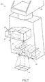
- FIG. 1 shows the sampling system 100, which is mounted to a work machine 101.
- the sampling system 100 according to the present embodiment is provided on the bottom surface of the work machine 101.
- the work machine 101 of the present embodiment is a landing probe that lands on a ground surface and then performs probing.
- the work machine 101 may be a different type of exploration probe such as an exploration rover, or may be, for example, a robot that performs work different from probing.
- FIG. 2 is an overall view of the sampling system 100
- FIG. 3 is a block diagram of a control system of the sampling system 100.
- the sampling system 100 includes a first sensor 10, an arm 20, a sampler 30, a second sensor 40, and a controller 50.
- a first sensor 10 an arm 20, a sampler 30, a second sensor 40, and a controller 50.
- the first sensor 10 is a sensor provided on the work machine 101.
- the first sensor 10 of the present embodiment includes a first projector 11 and a first camera 12.
- the first projector 11 projects a net-like grating.
- the first camera 12 captures an image of the grating that is displayed by projection. It should be noted that the first camera 12 is a stereoscopic camera.
- the first sensor 10 is electrically connected to the controller 50. Image data of the grating captured by the first camera 12 is transmitted to the controller 50.
- the arm 20 is a robotic arm, and its proximal end portion is provided on the work machine 101.
- the distal end portion of the arm 20 is provided with the sampler 30 and the second sensor 40.
- the arm 20 is electrically connected to the controller 50.
- the controller 50 is capable of driving the arm 20 arbitrarily by transmitting control signals to the arm 20.
- the sampler 30 is a piece of equipment configured to sample sand or the like on the ground surface (i.e., a piece of equipment for bringing back a sample of the ground surface).
- FIG. 4 is an enlarged view of the vicinity of the distal end portion of the arm 20.
- the sampling system 100 of the present embodiment includes an external cylinder member 32.
- the sampler 30 is accommodated inside the external cylinder member 32.
- the sampler 30 has a cylindrical shape.
- the sampler 30 is thrown against, and thereby inserted into, the ground surface by a sampler throwing and inserting device 31. After the sampler 30 is thrown and inserted into the ground surface, the sampler 30 is pulled out of the ground surface, and thereby the sand or the like in the sampler 30 can be collected.
- the second sensor 40 is a sensor provided on the distal end portion of the arm 20.
- the second sensor 40 includes: a second projector 41 configured to project a reference mark 44 (see FIG. 5 ), which will be described below; a second camera 42 configured to capture an image of the reference mark 44, which is displayed by projection; and an illuminator 43 configured to emit light in a direction in which the reference mark 44 is projected.
- the second camera 42 is a stereoscopic camera.
- the second sensor 40 is electrically connected to the controller 50. Image data of the reference mark 44 captured by the second camera 42 is transmitted to the controller 50.
- the second sensor 40 has a higher detection precision than the first sensor 10. The reason for this is as follows: the image-capturing range of the second camera 42 is narrower than the image-capturing range of the first camera 12; therefore, in the image-capturing range of the second camera 42, the number of pixels of the second camera 42 is greater than the number of pixels of the first camera 12.
- FIGS. 5A to 5F show examples of the aforementioned reference mark 44.
- the present embodiment adopts the reference mark 44 shown in FIG. 5A .
- the reference mark 44 of the present embodiment is constituted by a circular line 45 and two straight lines 46. Each straight line 46 passes through the center of the circular line 45, and both end portions of each straight line 46 cross the circular line 45.
- the reference mark 44 may include a rectangular line 47 as shown in FIG. 5B instead of the circular line 45.
- the reference mark 44 may include a polygonal line 48 as shown in FIG. 5C .
- the reference mark 44 may include a smaller-diameter circular line 49, which has a diameter less than the diameter of the circular line 45, as shown in FIG. 5D . Still further alternatively, the reference mark 44 may be constituted by the circular line 45 and one straight line 46 as shown in FIG. 5E . Still further alternatively, the reference mark 44 may be constituted only by the circular line 45 as shown in FIG. 5F .
- the controller 50 is a device configured to control various pieces of equipment.
- the controller 50 includes a processor, a volatile memory, a nonvolatile memory, an I/O interface, etc. As shown in FIG. 3 , the controller 50 is electrically connected to the first sensor 10 and the second sensor 40.
- the controller 50 is capable of obtaining image data transmitted from the first sensor 10 and the second sensor 40 and performing arbitrary control by transmitting control signals to the first sensor 10 and the second sensor 40.
- the controller 50 is electrically connected also to the arm 20 and the sampler throwing and inserting device 31.
- the controller 50 is capable of performing arbitrary control by transmitting control signals to the arm 20 and the sampler throwing and inserting device 31.
- FIG. 6 is a flowchart of control according to the sampling method of the present embodiment.
- the control shown in FIG. 6 is performed by the controller 50.
- sampling is performed on a ground surface where large and small obstacles exist sparsely.
- obstacle is defined herein to include not only rocks and stones, but also anything formed by unevenness of the ground surface.
- the controller 50 obtains topographical information about a wide area 13 on the ground surface from the first sensor 10 (step S1). Specifically, the controller 50 causes the first projector 11 provided on the work machine 101 to project a net-like grating onto the wide area 13 on the ground surface, causes the first camera 12 to capture an image of the grating that is displayed on the wide area 13 by projection, and obtains image data of the grating captured by the first camera 12. That is, the topographical information in step S1 is the image data of the grating.
- the controller 50 calculates a three-dimensional shape of the wide area 13 (step S2).
- the three-dimensional shape of the wide area 13 can be calculated by a known grating projection technique. Specifically, the image of the grating is binarized by using the image data, and thereby the grating is recognized. Then, the coordinates of a portion onto which the grating is projected are calculated based on the degree of distortion of the grating. It should be noted that the three-dimensional shape of the wide area 13 may be calculated not by the controller 50, but by the first sensor 10. In this case, the controller 50 obtains, from the first sensor 10, the three-dimensional shape data of the wide area 13 as the topographical information about the wide area 13.
- the controller 50 selects a candidate area 14 within the wide area 13 based on the three-dimensional shape of the wide area 13 (step S3). It should be noted that the candidate area 14 has an area less than the area of the wide area 13. In the present embodiment, a flat area with no obstacles is selected as the candidate area 14. However, since the detection precision of the first sensor 10 of the present embodiment is not high, it is possible that small obstacles exist in the candidate area 14 selected in step S3.
- the controller 50 checks the state of the arm 20 (step S4). Specifically, the controller 50 causes the first camera 12 to capture an image of the arm 20, and confirms that there is no abnormality, such as damage, on the arm 20 as well as checks the position of the distal end portion of the arm 20. It should be noted that, hereinafter, the position of the distal end portion of the arm 20 at the time is referred to as "standby position".
- the controller 50 sets a movement route based on the three-dimensional shape of the wide area 13 (step S5).
- the movement route is a route for the arm 20 to move from the "standby position" to a "preparation position" that faces the candidate area 14. For example, if it can be confirmed that there is no obstacle between the standby position and the preparation position based on the three-dimensional shape of the wide area 13, a route that is obtained by linearly connecting between the standby position and the preparation position is set as the movement route. On the other hand, if it is found that there is an obstacle between the standby position and the preparation position, a route that detours around the obstacle is set as the movement route.
- the movement route is a route that allows the distal end portion of the arm 20 to move from the standby position to the preparation position without coming into contact with the obstacle.
- the preparation position in the present embodiment is located vertically above the candidate area 14. However, for example, if the movable range of the arm 20 is limited, the preparation position need not be located vertically above the candidate area 14.
- the controller 50 causes the second projector 41 provided on the distal end portion of the arm 20 to project the reference mark 44 in the advancing direction of the distal end portion of the arm 20 (step S6).
- the movement route is a route that linearly connects between the standby position and the preparation position.
- the second projector 41 projects the reference mark 44 toward the preparation position.
- the controller 50 determines whether or not there is no obstacle on the movement route (step S7).
- the controller 50 causes the second camera 42 to capture an image of the reference mark 44 projected by the second projector 41, thereby obtaining image data. If the reference mark 44 cannot be recognized as a result of analyzing the image data, or if the size of the recognized reference mark 44 is greater than or equal to a particular value, i.e., the distance to an obstacle on which the reference mark 44 is displayed by projection is far, then it can be determined that there is no obstacle on the movement route. On the other hand, if the size of the reference mark 44 is less than the particular value, it can be determined that there is an obstacle on the movement route.
- step S7 If it is determined in step S7 that there is an obstacle on the movement route (NO in step S7), the controller 50 changes the advancing direction of the distal end portion of the arm 20, thereby changing the movement route (step S8). Thereafter, the flow returns to step S6. On the other hand, if it is determined in step S7 that there is no obstacle on the movement route (YES in step S7), the controller 50 moves the distal end portion of the arm 20 along the movement route (step S9).
- step S10 determines whether or not the distal end portion of the arm 20 has reached the preparation position. If it is determined that the distal end portion of the arm 20 has not yet reached the preparation position (NO in step S10), the flow returns to step S6. On the other hand, if it is determined that the distal end portion of the arm 20 has reached the preparation position (YES in step S10), the flow proceeds to step S11. That is, until the distal end portion of the arm 20 reaches the preparation position, the controller 50 moves the distal end portion of the arm 20 while repeatedly performing steps S6 to S10.
- the movement route is set in step S5 so as to allow the distal end portion of the arm 20 to move to the preparation position without coming into contact with any obstacles.
- steps S6 to S10 it is further determined whether or not there is an obstacle on the movement route.
- the distal end portion of the arm 20 is moved in a manner to avoid the obstacle.
- double preventative measures are taken so that the distal end portion of the arm 20 will not come into contact with any obstacles. This makes it possible to assuredly prevent the distal end portion of the arm 20, which is provided with the sampler 30 and the second sensor 40, from coming into contact with any obstacles.
- the controller 50 causes the second projector 41 to project the reference mark 44 onto the candidate area 14 selected in step S3 (step S11). Then, the controller 50 determines whether or not the diameter of the circular line 45 included in the reference mark 44 displayed on the candidate area 14 by projection coincides with the diameter of the sampler 30 (step S12). The controller 50 obtains, by the second camera 42, the image data of the reference mark 44 displayed on the candidate area 14 by projection, and performs the determination based on the obtained image data.
- step S12 If it is determined in step S12 that the diameter of the circular line 45 displayed on the candidate area 14 by projection does not coincide with the diameter of the sampler 30 (NO in step S12), the controller 50 moves the arm 20 such that the diameter of the circular line 45 displayed on the candidate area 14 by projection coincides with the diameter of the sampler 30, thereby adjusting the vertical position of the distal end portion of the arm 20 (step S13). Specifically, if the diameter of the circular line 45 displayed on the candidate area 14 by projection is less than the diameter of the sampler 30, the controller 50 moves the distal end portion of the arm 20 upward. On the other hand, if the diameter of the circular line 45 displayed on the candidate area 14 by projection is greater than the diameter of the sampler 30, the controller 50 moves the distal end portion of the arm 20 downward. After the vertical position of the distal end portion of the arm 20 is adjusted, the flow returns to step S11.
- step S12 determines in step S12 that the diameter of the circular line 45 displayed on the candidate area 14 by projection coincides with the diameter of the sampler 30 (NO in step S12), the flow proceeds to step S14.
- step S14 it is determined whether or not there is no obstacle in the candidate area 14. For example, based on the image data of the reference mark 44 captured by the second camera 42, the controller 50 performs binarization of the image, thereby recognizing the reference mark 44. If the amount of distortion of the recognized reference mark 44 is greater than or equal to a particular value, it can be determined that there is an obstacle in the candidate area 14. On the other hand, if the amount of distortion of the reference mark 44 is less than the particular value, it can be determined that there is no obstacle in the candidate area 14.
- step S15 If the controller 50 determines in step S14 that there is an obstacle in the candidate area 14 (NO in step S14), the controller 50 changes the candidate area 14 (step S15). In the present embodiment, an area adjacent to the current candidate area 14 is set as a new candidate area 14. Alternatively, the flow may return to step S3, in which the candidate area 14 is selected again. After the candidate area 14 is changed, the controller 50 moves the distal end portion of the arm 20 to a new preparation position that is located vertically above the changed candidate area 14 (step S16). After the distal end portion of the arm 20 is moved to the preparation position, the flow returns to step S11.
- step S14 determines whether there is no obstacle in the candidate area 14 (YES in step S14).
- the controller 50 sets the candidate area 14 as a sampling point (step S17). Then, the controller 50 performs sampling at the sampling point (step S18).
- the sampling is performed in the following manner.
- the sampler 30 is thrown and inserted into the sampling point by the sampler throwing and inserting device 31, such that the sampler 30 is embedded into the ground surface to a particular depth. Thereafter, the sampler 30, which contains the sand or the like of the ground surface, is collected by pulling out the sampler 30 from the ground surface, and thus the sampling is completed.
- the sampling system 100 and the sampling method according to the present embodiment are as described above.
- the topographical information about the wide area 13, which is obtained by using the first sensor 10 is used merely for selecting the candidate area 14. Therefore, the first sensor 10 is not required to have a high detection precision. For this reason, the detection by the first sensor 10 can be performed speedily.
- the topographical information obtained by using the second sensor 40 is information about the candidate area 14, whose area is small. For this reason, the detection by the second sensor 40 can be performed speedily.
- the sampling method according to the present embodiment makes it possible to specify the sampling point speedily, consequently making it possible to perform the sampling speedily.
- the circular line 45 the shape of which is the same as the cross-sectional shape of the sampler 30, is projected onto the ground surface, and the diameter of the circular line 45 displayed on the ground surface by projection is made coincide with the diameter of the sampler 30. Then, the sampling point is specified by utilizing the circular line 45 displayed on the ground surface by projection. In this manner, the sampling point can be specified by the detection that covers only the range corresponding to the shape and the size of the sampler 30. This makes it possible to efficiently specify the sampling point. Consequently, the sampling can be performed speedily.
- the sampling method according to the present embodiment is realized by the control performed by the controller 50.
- part of the control may be performed by an operator.
- the selection of the candidate area 14 may be performed by an operator.
- step S3 only one candidate area 14 is selected.
- a plurality of candidate areas 14 may be selected.
- the second projector 41 projects the reference mark 44.
- the second projector 41 may project a net-like grating.
- the three-dimensional shape of the candidate area 14 may be calculated by grating projection technique, and based on the calculated three-dimensional shape, the sampling point may be set.
- the sampling is not thus limited.
- the sampling may be performed by using a gear type sampler 33.
- the reference mark 44 has a shape corresponding to a sampling region on which the sampler 33 performs the sampling.
- the distal end of the arm 20 may be provided with a hand that is configured to hold a sampling target in a sandwiching manner, and sand or the like may be collected by using the hand.
- the sampling may be performed by using a scoop or brush.
Landscapes
- Engineering & Computer Science (AREA)
- Remote Sensing (AREA)
- Physics & Mathematics (AREA)
- General Physics & Mathematics (AREA)
- Theoretical Computer Science (AREA)
- Aviation & Aerospace Engineering (AREA)
- Multimedia (AREA)
- Astronomy & Astrophysics (AREA)
- Chemical & Material Sciences (AREA)
- Radar, Positioning & Navigation (AREA)
- Combustion & Propulsion (AREA)
- Computer Vision & Pattern Recognition (AREA)
- Life Sciences & Earth Sciences (AREA)
- Sustainable Development (AREA)
- Manipulator (AREA)
Abstract
Description
- The present invention relates to a sampling method of and a sampling system for performing sampling on a ground surface.
- In a case where a work machine, such as an exploration probe, performs sampling on a ground surface, it is necessary to specify a sampling point first. Desirably, the sampling point is a flat surface without obstacles, such as rocks and stones. At the time of specifying the sampling point, if there is a relatively large obstacle, the obstacle can be detected by a sensor (including a camera) provided on the work machine (see
Patent Literature 1, for example). - PTL 1: Japanese Laid-Open Patent Application Publication No.
H09-301300 - However, the detection precision of the sensor provided on the work machine is not high due to its wide detection range. Therefore, the sensor is not suitable for detecting small obstacles, such as small stones. If the detection precision of the sensor is set high, the sensor will be able to detect small obstacles. In this case, however, if the detection precision of the sensor is set high while still keeping its wide detection range, then the processing time will be lengthy, and the sampling cannot be performed speedily.
- The present invention has been made in view of the above, and an object of the present invention is to provide a sampling method and a sampling system that are capable of performing sampling speedily.
- A sampling method according to one aspect of the present invention includes: obtaining topographical information about a predetermined wide area by using a first sensor provided on a work machine; selecting a candidate area within the wide area based on the topographical information about the wide area, the candidate area having an area less than an area of the wide area, and setting a movement route based on the topographical information about the wide area, the movement route being a route that allows a distal end portion of an arm provided on the work machine to reach a preparation position without coming into contact with an obstacle, the preparation position facing the candidate area; moving the distal end portion of the arm along the movement route to the preparation position, and thereafter obtaining topographical information about the candidate area by using a second sensor provided on the distal end portion of the arm; and specifying a sampling point based on the topographical information about the candidate area and performing sampling at the specified sampling point.
- In the above method, the topographical information about the wide area, which is obtained by using the first sensor, is used merely for setting the candidate area. Therefore, the first sensor is not required to have a high detection precision. For this reason, the detection by the first sensor can be performed speedily. Moreover, the topographical information obtained by using the second sensor is information about the candidate area, whose area is relatively small. For this reason, the detection by the second sensor can be performed speedily. Thus, the above sampling method makes it possible to specify the sampling point speedily, consequently making it possible to perform the sampling speedily. In addition, in the above sampling method, the movement route, which does not cause the distal end portion of the arm to come into contact with the obstacle, is set based on the topographical information about the wide area, and the distal end portion of the arm is moved along the movement route. Therefore, the distal end portion of the arm can be prevented from coming into contact with the obstacle, and pieces of equipment provided on the distal end portion of the arm can be prevented from getting damaged.
- In the above sampling method, the second sensor may include a projector configured to project a predetermined reference mark, and obtaining the topographical information about the candidate area may include: projecting the reference mark onto the candidate area; and obtaining the topographical information about the candidate area based on a shape of the reference mark that is displayed on the candidate area by projection.
- According to this method, the topographical information about the candidate area can be obtained speedily and accurately with a simple configuration.
- The above sampling method may include projecting the reference mark from the projector in an advancing direction of the distal end portion of the arm when moving the distal end portion of the arm to the preparation position, determining whether or not there is an obstacle on the movement route based on presence or absence of a display of the reference mark by projection or based on a shape and a size of the reference mark displayed by projection, and if it is determined that there is an obstacle on the movement route, moving the distal end portion of the arm to the preparation position in a manner to avoid the obstacle.
- According to this method, even if there is an obstacle on the movement route, the distal end portion of the arm is moved in a manner to avoid the obstacle. This makes it possible to more assuredly prevent damage to the pieces of equipment provided on the distal end portion of the arm.
- A sampling system according to one aspect of the present invention includes: a sampler for bringing back a sample of a ground surface; a projector configured to project a reference mark onto the ground surface, the reference mark including a line that has a predetermined shape; a camera configured to capture an image of the reference mark that is displayed on the ground surface by projection; an arm whose distal end portion is provided with the sampler, the projector, and the camera; and a controller configured to: obtain a size of the line that is displayed on the ground surface by projection, based on image data of the reference mark captured by the camera; adjust a height position of the projector based on the obtained size of the line; and thereafter specify a sampling point, into which the sampler is thrown and inserted, based on the image data of the reference mark captured by the camera.
- According to this configuration, the sampling point, into which the sampler is thrown and inserted, is specified by capturing an image of the reference mark projected onto the ground surface. Accordingly, inspection of the ground surface can be performed speedily, and also, the sampling can be performed in a manner to avoid small stones or the like. Therefore, the above configuration is particularly useful in a case where the presence of small stones or the like would hinder the sampling, for example, a case where the sampler is inserted into the ground surface or a case where the use of a gear type sampler is adopted.
- In the above sampling system, the sampler may have a cylindrical shape. The reference mark may include a circular line. The controller may be configured to: obtain a diameter of the circular line that is displayed on the ground surface by projection, based on the image data of the reference mark captured by the camera; adjust a height position of the projector by driving the arm, such that the obtained diameter of the circular line coincides with a diameter of the sampler; and thereafter specify the sampling point, into which the sampler is thrown and inserted, based on the image data of the reference mark captured by the camera.
- According to this configuration, the circular line, the shape of which is the same as the cross-sectional shape of the sampler, is projected onto the ground surface, and the diameter of the circular line displayed on the ground surface by projection is made coincide with the diameter of the sampler. Then, the sampling point is specified by utilizing the circular line displayed on the ground surface by projection. That is, the sampling point can be specified by the detection that covers only the range corresponding to the shape and the size of the sampler. This makes it possible to efficiently specify the sampling point. Consequently, the sampling can be performed speedily.
- In the above sampling system, the reference mark may include one or two straight lines passing through a center of the circular line, each straight line having both end portions crossing the circular line.
- Here, when measuring the diameter of the circular line, there is a case where it is not clear which two points on the circular line should be used to measure an inter-point distance therebetween to obtain the diameter of the circular line. In this respect, in the above configuration, the diameter of the circular line can be obtained by measuring the distance between the intersection points of the straight line and the circular line. Therefore, the diameter of the circular line can be accurately and readily obtained. Moreover, since the straight line passes through the inside of the circular line, irregularities of the ground surface can be detected also inside the circular line. Therefore, detection precision can be improved by the above configuration.
- In the above sampling system, the reference mark may include a smaller-diameter circular line inside the circular line, the smaller-diameter circular line having a diameter less than the diameter of the circular line.
- According to this configuration, since the smaller-diameter circular line is positioned inside the circular line, irregularities of the ground surface can be detected also inside the circular line. Therefore, detection precision can be improved by the above configuration.
- The above configurations make it possible to provide a sampling method and a sampling system that are capable of performing sampling speedily.
-
-
FIG. 1 shows a sampling system mounted to a work machine. -
FIG. 2 is an overall view of the sampling system. -
FIG. 3 is a block diagram of a control system of the sampling system. -
FIG. 4 is an enlarged view of the vicinity of the distal end portion of an arm. -
FIGS. 5A to 5F show examples of a reference mark. -
FIG. 6 is a flowchart of control according to a sampling method. -
FIG. 7 is an enlarged view of the vicinity of the distal end portion of the arm according to a variation. - Hereinafter, an embodiment of the present invention is described with reference to the drawings. First, an overall configuration of a
sampling system 100 is described.FIG. 1 shows thesampling system 100, which is mounted to awork machine 101. Thesampling system 100 according to the present embodiment is provided on the bottom surface of thework machine 101. Thework machine 101 of the present embodiment is a landing probe that lands on a ground surface and then performs probing. Alternatively, thework machine 101 may be a different type of exploration probe such as an exploration rover, or may be, for example, a robot that performs work different from probing. -
FIG. 2 is an overall view of thesampling system 100, andFIG. 3 is a block diagram of a control system of thesampling system 100. As shown inFIG. 2 andFIG. 3 , thesampling system 100 includes afirst sensor 10, anarm 20, asampler 30, asecond sensor 40, and acontroller 50. Hereinafter, these components are described sequentially. - The
first sensor 10 is a sensor provided on thework machine 101. Thefirst sensor 10 of the present embodiment includes afirst projector 11 and afirst camera 12. Thefirst projector 11 projects a net-like grating. Thefirst camera 12 captures an image of the grating that is displayed by projection. It should be noted that thefirst camera 12 is a stereoscopic camera. As shown inFIG. 3 , thefirst sensor 10 is electrically connected to thecontroller 50. Image data of the grating captured by thefirst camera 12 is transmitted to thecontroller 50. - The
arm 20 is a robotic arm, and its proximal end portion is provided on thework machine 101. The distal end portion of thearm 20 is provided with thesampler 30 and thesecond sensor 40. Thearm 20 is electrically connected to thecontroller 50. Thecontroller 50 is capable of driving thearm 20 arbitrarily by transmitting control signals to thearm 20. - The
sampler 30 is a piece of equipment configured to sample sand or the like on the ground surface (i.e., a piece of equipment for bringing back a sample of the ground surface).FIG. 4 is an enlarged view of the vicinity of the distal end portion of thearm 20. As shown inFIG. 4 , thesampling system 100 of the present embodiment includes anexternal cylinder member 32. Thesampler 30 is accommodated inside theexternal cylinder member 32. Thesampler 30 has a cylindrical shape. Thesampler 30 is thrown against, and thereby inserted into, the ground surface by a sampler throwing and insertingdevice 31. After thesampler 30 is thrown and inserted into the ground surface, thesampler 30 is pulled out of the ground surface, and thereby the sand or the like in thesampler 30 can be collected. - The
second sensor 40 is a sensor provided on the distal end portion of thearm 20. Thesecond sensor 40 includes: asecond projector 41 configured to project a reference mark 44 (seeFIG. 5 ), which will be described below; asecond camera 42 configured to capture an image of thereference mark 44, which is displayed by projection; and anilluminator 43 configured to emit light in a direction in which thereference mark 44 is projected. Thesecond camera 42 is a stereoscopic camera. Thesecond sensor 40 is electrically connected to thecontroller 50. Image data of thereference mark 44 captured by thesecond camera 42 is transmitted to thecontroller 50. - It should be noted that when the distance from the
second projector 41 to its detection target is long, the size of thereference mark 44 displayed on the detection target by projection is large, whereas when the distance from thesecond projector 41 to the detection target is short, the size of thereference mark 44 displayed on the detection target by projection is small. Thesecond sensor 40 has a higher detection precision than thefirst sensor 10. The reason for this is as follows: the image-capturing range of thesecond camera 42 is narrower than the image-capturing range of thefirst camera 12; therefore, in the image-capturing range of thesecond camera 42, the number of pixels of thesecond camera 42 is greater than the number of pixels of thefirst camera 12. -
FIGS. 5A to 5F show examples of theaforementioned reference mark 44. The present embodiment adopts thereference mark 44 shown inFIG. 5A . Specifically, thereference mark 44 of the present embodiment is constituted by acircular line 45 and twostraight lines 46. Eachstraight line 46 passes through the center of thecircular line 45, and both end portions of eachstraight line 46 cross thecircular line 45. Alternatively, thereference mark 44 may include arectangular line 47 as shown inFIG. 5B instead of thecircular line 45. Further alternatively, thereference mark 44 may include apolygonal line 48 as shown inFIG. 5C . Still further alternatively, inside thecircular line 45, thereference mark 44 may include a smaller-diametercircular line 49, which has a diameter less than the diameter of thecircular line 45, as shown inFIG. 5D . Still further alternatively, thereference mark 44 may be constituted by thecircular line 45 and onestraight line 46 as shown inFIG. 5E . Still further alternatively, thereference mark 44 may be constituted only by thecircular line 45 as shown inFIG. 5F . - The
controller 50 is a device configured to control various pieces of equipment. Thecontroller 50 includes a processor, a volatile memory, a nonvolatile memory, an I/O interface, etc. As shown inFIG. 3 , thecontroller 50 is electrically connected to thefirst sensor 10 and thesecond sensor 40. Thecontroller 50 is capable of obtaining image data transmitted from thefirst sensor 10 and thesecond sensor 40 and performing arbitrary control by transmitting control signals to thefirst sensor 10 and thesecond sensor 40. Thecontroller 50 is electrically connected also to thearm 20 and the sampler throwing and insertingdevice 31. Thecontroller 50 is capable of performing arbitrary control by transmitting control signals to thearm 20 and the sampler throwing and insertingdevice 31. - Next, a sampling method according to the present embodiment is described.
FIG. 6 is a flowchart of control according to the sampling method of the present embodiment. The control shown inFIG. 6 is performed by thecontroller 50. In the present embodiment, it is assumed that sampling is performed on a ground surface where large and small obstacles exist sparsely. It should be noted that the term "obstacle" is defined herein to include not only rocks and stones, but also anything formed by unevenness of the ground surface. - First, as shown in
FIG. 6 , when the control starts, thecontroller 50 obtains topographical information about awide area 13 on the ground surface from the first sensor 10 (step S1). Specifically, thecontroller 50 causes thefirst projector 11 provided on thework machine 101 to project a net-like grating onto thewide area 13 on the ground surface, causes thefirst camera 12 to capture an image of the grating that is displayed on thewide area 13 by projection, and obtains image data of the grating captured by thefirst camera 12. That is, the topographical information in step S1 is the image data of the grating. - Next, based on the topographical information about the wide area 13 (the image data) obtained in step S1, the
controller 50 calculates a three-dimensional shape of the wide area 13 (step S2). The three-dimensional shape of thewide area 13 can be calculated by a known grating projection technique. Specifically, the image of the grating is binarized by using the image data, and thereby the grating is recognized. Then, the coordinates of a portion onto which the grating is projected are calculated based on the degree of distortion of the grating. It should be noted that the three-dimensional shape of thewide area 13 may be calculated not by thecontroller 50, but by thefirst sensor 10. In this case, thecontroller 50 obtains, from thefirst sensor 10, the three-dimensional shape data of thewide area 13 as the topographical information about thewide area 13. - Next, the
controller 50 selects acandidate area 14 within thewide area 13 based on the three-dimensional shape of the wide area 13 (step S3). It should be noted that thecandidate area 14 has an area less than the area of thewide area 13. In the present embodiment, a flat area with no obstacles is selected as thecandidate area 14. However, since the detection precision of thefirst sensor 10 of the present embodiment is not high, it is possible that small obstacles exist in thecandidate area 14 selected in step S3. - Next, the
controller 50 checks the state of the arm 20 (step S4). Specifically, thecontroller 50 causes thefirst camera 12 to capture an image of thearm 20, and confirms that there is no abnormality, such as damage, on thearm 20 as well as checks the position of the distal end portion of thearm 20. It should be noted that, hereinafter, the position of the distal end portion of thearm 20 at the time is referred to as "standby position". - Next, the
controller 50 sets a movement route based on the three-dimensional shape of the wide area 13 (step S5). The movement route is a route for thearm 20 to move from the "standby position" to a "preparation position" that faces thecandidate area 14. For example, if it can be confirmed that there is no obstacle between the standby position and the preparation position based on the three-dimensional shape of thewide area 13, a route that is obtained by linearly connecting between the standby position and the preparation position is set as the movement route. On the other hand, if it is found that there is an obstacle between the standby position and the preparation position, a route that detours around the obstacle is set as the movement route. That is, the movement route is a route that allows the distal end portion of thearm 20 to move from the standby position to the preparation position without coming into contact with the obstacle. It should be noted that the preparation position in the present embodiment is located vertically above thecandidate area 14. However, for example, if the movable range of thearm 20 is limited, the preparation position need not be located vertically above thecandidate area 14. - Next, before moving the distal end portion of the
arm 20, thecontroller 50 causes thesecond projector 41 provided on the distal end portion of thearm 20 to project thereference mark 44 in the advancing direction of the distal end portion of the arm 20 (step S6). For example, assume that the distal end portion of thearm 20 is at the standby position, and the movement route is a route that linearly connects between the standby position and the preparation position. In this case, thesecond projector 41 projects thereference mark 44 toward the preparation position. - Subsequently, the
controller 50 determines whether or not there is no obstacle on the movement route (step S7). Thecontroller 50 causes thesecond camera 42 to capture an image of thereference mark 44 projected by thesecond projector 41, thereby obtaining image data. If thereference mark 44 cannot be recognized as a result of analyzing the image data, or if the size of the recognizedreference mark 44 is greater than or equal to a particular value, i.e., the distance to an obstacle on which thereference mark 44 is displayed by projection is far, then it can be determined that there is no obstacle on the movement route. On the other hand, if the size of thereference mark 44 is less than the particular value, it can be determined that there is an obstacle on the movement route. - If it is determined in step S7 that there is an obstacle on the movement route (NO in step S7), the
controller 50 changes the advancing direction of the distal end portion of thearm 20, thereby changing the movement route (step S8). Thereafter, the flow returns to step S6. On the other hand, if it is determined in step S7 that there is no obstacle on the movement route (YES in step S7), thecontroller 50 moves the distal end portion of thearm 20 along the movement route (step S9). - Then, the
controller 50 determines whether or not the distal end portion of thearm 20 has reached the preparation position (step S10). If it is determined that the distal end portion of thearm 20 has not yet reached the preparation position (NO in step S10), the flow returns to step S6. On the other hand, if it is determined that the distal end portion of thearm 20 has reached the preparation position (YES in step S10), the flow proceeds to step S11. That is, until the distal end portion of thearm 20 reaches the preparation position, thecontroller 50 moves the distal end portion of thearm 20 while repeatedly performing steps S6 to S10. - In the present embodiment, the movement route is set in step S5 so as to allow the distal end portion of the
arm 20 to move to the preparation position without coming into contact with any obstacles. In addition, in steps S6 to S10, it is further determined whether or not there is an obstacle on the movement route. In a case where there is an obstacle on the movement route, the distal end portion of thearm 20 is moved in a manner to avoid the obstacle. Thus, in the present embodiment, double preventative measures are taken so that the distal end portion of thearm 20 will not come into contact with any obstacles. This makes it possible to assuredly prevent the distal end portion of thearm 20, which is provided with thesampler 30 and thesecond sensor 40, from coming into contact with any obstacles. - Next, the
controller 50 causes thesecond projector 41 to project thereference mark 44 onto thecandidate area 14 selected in step S3 (step S11). Then, thecontroller 50 determines whether or not the diameter of thecircular line 45 included in thereference mark 44 displayed on thecandidate area 14 by projection coincides with the diameter of the sampler 30 (step S12). Thecontroller 50 obtains, by thesecond camera 42, the image data of thereference mark 44 displayed on thecandidate area 14 by projection, and performs the determination based on the obtained image data. - If it is determined in step S12 that the diameter of the
circular line 45 displayed on thecandidate area 14 by projection does not coincide with the diameter of the sampler 30 (NO in step S12), thecontroller 50 moves thearm 20 such that the diameter of thecircular line 45 displayed on thecandidate area 14 by projection coincides with the diameter of thesampler 30, thereby adjusting the vertical position of the distal end portion of the arm 20 (step S13). Specifically, if the diameter of thecircular line 45 displayed on thecandidate area 14 by projection is less than the diameter of thesampler 30, thecontroller 50 moves the distal end portion of thearm 20 upward. On the other hand, if the diameter of thecircular line 45 displayed on thecandidate area 14 by projection is greater than the diameter of thesampler 30, thecontroller 50 moves the distal end portion of thearm 20 downward. After the vertical position of the distal end portion of thearm 20 is adjusted, the flow returns to step S11. - On the other hand, if the
controller 50 determines in step S12 that the diameter of thecircular line 45 displayed on thecandidate area 14 by projection coincides with the diameter of the sampler 30 (NO in step S12), the flow proceeds to step S14. - In step S14, it is determined whether or not there is no obstacle in the
candidate area 14. For example, based on the image data of thereference mark 44 captured by thesecond camera 42, thecontroller 50 performs binarization of the image, thereby recognizing thereference mark 44. If the amount of distortion of the recognizedreference mark 44 is greater than or equal to a particular value, it can be determined that there is an obstacle in thecandidate area 14. On the other hand, if the amount of distortion of thereference mark 44 is less than the particular value, it can be determined that there is no obstacle in thecandidate area 14. - If the
controller 50 determines in step S14 that there is an obstacle in the candidate area 14 (NO in step S14), thecontroller 50 changes the candidate area 14 (step S15). In the present embodiment, an area adjacent to thecurrent candidate area 14 is set as anew candidate area 14. Alternatively, the flow may return to step S3, in which thecandidate area 14 is selected again. After thecandidate area 14 is changed, thecontroller 50 moves the distal end portion of thearm 20 to a new preparation position that is located vertically above the changed candidate area 14 (step S16). After the distal end portion of thearm 20 is moved to the preparation position, the flow returns to step S11. - On the other hand, if it is determined in step S14 that there is no obstacle in the candidate area 14 (YES in step S14), the
controller 50 sets thecandidate area 14 as a sampling point (step S17). Then, thecontroller 50 performs sampling at the sampling point (step S18). The sampling is performed in the following manner. Thesampler 30 is thrown and inserted into the sampling point by the sampler throwing and insertingdevice 31, such that thesampler 30 is embedded into the ground surface to a particular depth. Thereafter, thesampler 30, which contains the sand or the like of the ground surface, is collected by pulling out thesampler 30 from the ground surface, and thus the sampling is completed. - The
sampling system 100 and the sampling method according to the present embodiment are as described above. In the sampling method according to the present embodiment, the topographical information about thewide area 13, which is obtained by using thefirst sensor 10, is used merely for selecting thecandidate area 14. Therefore, thefirst sensor 10 is not required to have a high detection precision. For this reason, the detection by thefirst sensor 10 can be performed speedily. Moreover, the topographical information obtained by using thesecond sensor 40 is information about thecandidate area 14, whose area is small. For this reason, the detection by thesecond sensor 40 can be performed speedily. Thus, the sampling method according to the present embodiment makes it possible to specify the sampling point speedily, consequently making it possible to perform the sampling speedily. - Further, according to the
sampling system 100 of the present embodiment, thecircular line 45, the shape of which is the same as the cross-sectional shape of thesampler 30, is projected onto the ground surface, and the diameter of thecircular line 45 displayed on the ground surface by projection is made coincide with the diameter of thesampler 30. Then, the sampling point is specified by utilizing thecircular line 45 displayed on the ground surface by projection. In this manner, the sampling point can be specified by the detection that covers only the range corresponding to the shape and the size of thesampler 30. This makes it possible to efficiently specify the sampling point. Consequently, the sampling can be performed speedily. - The sampling method according to the present embodiment is realized by the control performed by the
controller 50. Alternatively, part of the control may be performed by an operator. For example, the selection of thecandidate area 14 may be performed by an operator. Further, in the present embodiment, in step S3, only onecandidate area 14 is selected. Alternatively, a plurality ofcandidate areas 14 may be selected. - The above description of the sampling method according to the present embodiment gives an example case in which the
second projector 41 projects thereference mark 44. Alternatively, thesecond projector 41 may project a net-like grating. In this case, the three-dimensional shape of thecandidate area 14 may be calculated by grating projection technique, and based on the calculated three-dimensional shape, the sampling point may be set. - Although sand or the like is collected by using the
cylindrical sampler 30 in the present embodiment, the sampling is not thus limited. For example, as shown inFIG. 7 , the sampling may be performed by using agear type sampler 33. In this case, desirably, thereference mark 44 has a shape corresponding to a sampling region on which thesampler 33 performs the sampling. Alternatively, the distal end of thearm 20 may be provided with a hand that is configured to hold a sampling target in a sandwiching manner, and sand or the like may be collected by using the hand. Further alternatively, the sampling may be performed by using a scoop or brush. -
- 10
- first sensor
- 13
- wide area
- 14
- candidate area
- 20
- arm
- 30
- sampler
- 31
- sampler throwing and inserting device
- 33
- sampler
- 40
- second sensor
- 41
- second projector
- 42
- second camera
- 44
- reference mark
- 45
- circular line
- 46
- straight line
- 49
- smaller-diameter circular line
- 50
- controller
- 100
- sampling system
- 101
- work machine
Claims (7)
- A sampling method comprising:obtaining topographical information about a predetermined wide area by using a first sensor provided on a work machine;selecting a candidate area within the wide area based on the topographical information about the wide area, the candidate area having an area less than an area of the wide area, and setting a movement route based on the topographical information about the wide area, the movement route being a route that allows a distal end portion of an arm provided on the work machine to reach a preparation position without coming into contact with an obstacle, the preparation position facing the candidate area;moving the distal end portion of the arm along the movement route to the preparation position, and thereafter obtaining topographical information about the candidate area by using a second sensor provided on the distal end portion of the arm; andspecifying a sampling point based on the topographical information about the candidate area and performing sampling at the specified sampling point.
- The sampling method according to claim 1, wherein
the second sensor includes a projector configured to project a predetermined reference mark, and
obtaining the topographical information about the candidate area includes:projecting the reference mark onto the candidate area; andobtaining the topographical information about the candidate area based on a shape of the reference mark that is displayed on the candidate area by projection. - The sampling method according to claim 2, comprising projecting the reference mark from the projector in an advancing direction of the distal end portion of the arm when moving the distal end portion of the arm to the preparation position, determining whether or not there is an obstacle on the movement route based on presence or absence of a display of the reference mark by projection or based on a shape and a size of the reference mark displayed by projection, and if it is determined that there is an obstacle on the movement route, moving the distal end portion of the arm to the preparation position in a manner to avoid the obstacle.
- A sampling system comprising:a sampler for bringing back a sample of a ground surface;a projector configured to project a reference mark onto the ground surface, the reference mark including a line that has a predetermined shape;a camera configured to capture an image of the reference mark that is displayed on the ground surface by projection;an arm whose distal end portion is provided with the sampler, the projector, and the camera; anda controller configured to:obtain a size of the line that is displayed on the ground surface by projection, based on image data of the reference mark captured by the camera;adjust a height position of the projector based on the obtained size of the line; and thereafterspecify a sampling point, into which the sampler is thrown and inserted, based on the image data of the reference mark captured by the camera.
- The sampling system according to claim 4, wherein
the sampler has a cylindrical shape,
the reference mark includes a circular line, and
the controller is configured to:obtain a diameter of the circular line that is displayed on the ground surface by projection, based on the image data of the reference mark captured by the camera;adjust a height position of the projector by driving the arm, such that the obtained diameter of the circular line coincides with a diameter of the sampler; and thereafterspecify the sampling point, into which the sampler is thrown and inserted, based on the image data of the reference mark captured by the camera. - The sampling system according to claim 5, wherein
the reference mark includes one or two straight lines passing through a center of the circular line, each straight line having both end portions crossing the circular line. - The sampling system according to claim 5 or 6, wherein
the reference mark includes a smaller-diameter circular line inside the circular line, the smaller-diameter circular line having a diameter less than the diameter of the circular line.
Applications Claiming Priority (2)
| Application Number | Priority Date | Filing Date | Title |
|---|---|---|---|
| US201862668989P | 2018-05-09 | 2018-05-09 | |
| PCT/JP2019/018356 WO2019216336A1 (en) | 2018-05-09 | 2019-05-08 | Sampling method and sampling system |
Publications (3)
| Publication Number | Publication Date |
|---|---|
| EP3792189A1 true EP3792189A1 (en) | 2021-03-17 |
| EP3792189A4 EP3792189A4 (en) | 2022-01-26 |
| EP3792189B1 EP3792189B1 (en) | 2024-07-17 |
Family
ID=68466784
Family Applications (1)
| Application Number | Title | Priority Date | Filing Date |
|---|---|---|---|
| EP19799636.6A Active EP3792189B1 (en) | 2018-05-09 | 2019-05-08 | Sampling method and sampling system |
Country Status (5)
| Country | Link |
|---|---|
| US (2) | US11926440B2 (en) |
| EP (1) | EP3792189B1 (en) |
| JP (2) | JP7181926B2 (en) |
| CA (2) | CA3097102C (en) |
| WO (1) | WO2019216336A1 (en) |
Families Citing this family (8)
| Publication number | Priority date | Publication date | Assignee | Title |
|---|---|---|---|---|
| CN111762341B (en) * | 2020-07-06 | 2021-10-22 | 北京理工大学 | Multi-mode switching guidance method for secure attachment for online extraction of small celestial topography features |
| CN112255008B (en) * | 2020-09-16 | 2024-03-29 | 北京空间飞行器总体设计部 | A leg-arm multiplexed small celestial body attachment and sampling integrated detector |
| CN112629922B (en) * | 2020-12-31 | 2024-06-28 | 重庆壤科农业数据服务有限公司 | Unmanned aerial vehicle soil automatic sampler |
| CN113693636B (en) * | 2021-08-30 | 2023-11-24 | 南方科技大学 | Sampling methods, sampling systems and storage media |
| CN113788162B (en) * | 2021-09-18 | 2022-07-29 | 北京空间飞行器总体设计部 | High-performance Mars vehicle |
| EP4419427A4 (en) * | 2021-10-19 | 2025-07-23 | Lunar Outpost Inc | EXTENDABLE LADDER FOR HEAT MANAGEMENT |
| JP7785552B2 (en) * | 2022-01-27 | 2025-12-15 | 川崎重工業株式会社 | Sample transport device for space probe and space probe equipped with same |
| CN116460822B (en) * | 2022-10-29 | 2025-11-07 | 重庆大学 | Lifting base integrated rotary digging type ground surface sampling device |
Family Cites Families (20)
| Publication number | Priority date | Publication date | Assignee | Title |
|---|---|---|---|---|
| JPS5290246A (en) * | 1976-01-23 | 1977-07-29 | Hitachi Ltd | Material information input unit |
| JPH0361812A (en) * | 1989-07-31 | 1991-03-18 | Toshiba Corp | Proximity sensor |
| US5768940A (en) * | 1995-12-07 | 1998-06-23 | The Director-General Of The Institute Of Space And Astronautical Science | Sample collector |
| JPH09301300A (en) * | 1996-05-10 | 1997-11-25 | Mitsubishi Electric Corp | Landing point obstacle detection method for automatic landing gear |
| JP4448233B2 (en) * | 2000-05-19 | 2010-04-07 | 富士重工業株式会社 | Landing point search device, flying object using the same, and landing point evaluation device |
| JP4298155B2 (en) * | 2000-11-17 | 2009-07-15 | 本田技研工業株式会社 | Distance measuring device and distance measuring method |
| JP3870257B2 (en) | 2002-05-02 | 2007-01-17 | 独立行政法人 宇宙航空研究開発機構 | Robot with offset rotary joint |
| US20070030486A1 (en) * | 2005-08-08 | 2007-02-08 | Daniel Gelbart | Laser centering jig |
| US8019490B2 (en) * | 2006-09-29 | 2011-09-13 | Applied Minds, Llc | Imaging and display system to aid helicopter landings in brownout conditions |
| WO2009024756A1 (en) * | 2007-08-17 | 2009-02-26 | Renishaw Plc | Non-contact measurement apparatus and method |
| JP5653789B2 (en) | 2011-02-17 | 2015-01-14 | 株式会社 東京ウエルズ | Stepping motor drive method, drive system, and current pattern update device |
| US9266627B1 (en) * | 2012-04-24 | 2016-02-23 | Planetary Resources Development Corporation | Method, apparatus, and system for asteroid prospecting and mining |
| US9322651B2 (en) * | 2012-08-29 | 2016-04-26 | Ge Aviation Systems Llc | System and method for utilizing multiple sensors |
| US9102055B1 (en) * | 2013-03-15 | 2015-08-11 | Industrial Perception, Inc. | Detection and reconstruction of an environment to facilitate robotic interaction with the environment |
| US9617011B2 (en) * | 2014-06-24 | 2017-04-11 | Sikorsky Aircraft Corporation | Probabilistic safe landing area determination |
| US20160245641A1 (en) * | 2015-02-19 | 2016-08-25 | Microsoft Technology Licensing, Llc | Projection transformations for depth estimation |
| US9694498B2 (en) * | 2015-03-30 | 2017-07-04 | X Development Llc | Imager for detecting visual light and projected patterns |
| US9840003B2 (en) * | 2015-06-24 | 2017-12-12 | Brain Corporation | Apparatus and methods for safe navigation of robotic devices |
| JP2017015527A (en) * | 2015-06-30 | 2017-01-19 | 株式会社トプコン | Wide area sensor system, flight detection method and program |
| JP2018012184A (en) * | 2016-07-22 | 2018-01-25 | セイコーエプソン株式会社 | Control device, robot and robot system |
-
2019
- 2019-05-08 CA CA3097102A patent/CA3097102C/en active Active
- 2019-05-08 CA CA3153295A patent/CA3153295C/en active Active
- 2019-05-08 JP JP2020518314A patent/JP7181926B2/en active Active
- 2019-05-08 EP EP19799636.6A patent/EP3792189B1/en active Active
- 2019-05-08 WO PCT/JP2019/018356 patent/WO2019216336A1/en not_active Ceased
-
2020
- 2020-11-09 US US17/092,422 patent/US11926440B2/en active Active
-
2021
- 2021-10-04 JP JP2021163761A patent/JP7137679B2/en active Active
-
2023
- 2023-10-10 US US18/378,410 patent/US12116147B2/en active Active
Also Published As
| Publication number | Publication date |
|---|---|
| JP7137679B2 (en) | 2022-09-14 |
| JPWO2019216336A1 (en) | 2020-12-17 |
| US20210122500A1 (en) | 2021-04-29 |
| WO2019216336A1 (en) | 2019-11-14 |
| US20240034486A1 (en) | 2024-02-01 |
| US12116147B2 (en) | 2024-10-15 |
| CA3153295A1 (en) | 2019-11-14 |
| JP2022001485A (en) | 2022-01-06 |
| CA3153295C (en) | 2023-06-13 |
| CA3097102C (en) | 2023-01-03 |
| EP3792189A4 (en) | 2022-01-26 |
| EP3792189B1 (en) | 2024-07-17 |
| US11926440B2 (en) | 2024-03-12 |
| JP7181926B2 (en) | 2022-12-01 |
| CA3097102A1 (en) | 2019-11-14 |
Similar Documents
| Publication | Publication Date | Title |
|---|---|---|
| EP3792189B1 (en) | Sampling method and sampling system | |
| CN109577382B (en) | Pile head analysis system and method, and storage medium storing pile head analysis program | |
| CN108474747B (en) | Detection device and detection method | |
| CN110573855B (en) | Particle measuring device and particle measuring method | |
| JP3373831B2 (en) | Test specimen elongation measuring method and apparatus | |
| US20190170659A1 (en) | Defect inspection device, defect inspection method, and program | |
| JP7068307B2 (en) | Systems and methods for template-based image analysis | |
| US20140132729A1 (en) | Method and apparatus for camera-based 3d flaw tracking system | |
| JP2020073891A (en) | Image-based tray alignment and tube slot localization in vision system | |
| US12088910B2 (en) | Inspection workflow using object recognition and other techniques | |
| KR20160083895A (en) | Method and system for correlating optical images with scanning electron microscopy images | |
| JP6524529B2 (en) | Building limit judging device | |
| CN108474653A (en) | Three-dimensional measuring apparatus and its measurement aid in treatment method | |
| US10282837B2 (en) | Image measuring apparatus and non-temporary recording medium on which control program of same apparatus is recorded | |
| JP4757246B2 (en) | Nerve cell image analyzer and nerve cell image analysis software | |
| CN105014675B (en) | A kind of narrow space intelligent mobile robot vision navigation system and method | |
| CN110471086A (en) | A radar obstacle detection system and method | |
| JP2023029441A (en) | Measuring devices, measuring systems and vehicles | |
| CN109143167A (en) | A kind of complaint message acquisition device and method | |
| KR101563999B1 (en) | Method and System for measuring the state of Tire width and thickness | |
| JP4947592B2 (en) | Vehicle detection device | |
| CN115078372A (en) | Product process detection method, device, computer equipment and medium | |
| KR101428925B1 (en) | Width Measuring Device and Method using Laser | |
| JP6662126B2 (en) | Detecting device, method and program | |
| CN116128842B (en) | Material Sampling Method and Apparatus Based on Point Cloud Data |
Legal Events
| Date | Code | Title | Description |
|---|---|---|---|
| STAA | Information on the status of an ep patent application or granted ep patent |
Free format text: STATUS: THE INTERNATIONAL PUBLICATION HAS BEEN MADE |
|
| PUAI | Public reference made under article 153(3) epc to a published international application that has entered the european phase |
Free format text: ORIGINAL CODE: 0009012 |
|
| STAA | Information on the status of an ep patent application or granted ep patent |
Free format text: STATUS: REQUEST FOR EXAMINATION WAS MADE |
|
| 17P | Request for examination filed |
Effective date: 20201009 |
|
| AK | Designated contracting states |
Kind code of ref document: A1 Designated state(s): AL AT BE BG CH CY CZ DE DK EE ES FI FR GB GR HR HU IE IS IT LI LT LU LV MC MK MT NL NO PL PT RO RS SE SI SK SM TR |
|
| AX | Request for extension of the european patent |
Extension state: BA ME |
|
| DAV | Request for validation of the european patent (deleted) | ||
| DAX | Request for extension of the european patent (deleted) | ||
| REG | Reference to a national code |
Ref country code: DE Ref legal event code: R079 Free format text: PREVIOUS MAIN CLASS: B64G0001660000 Ipc: B64G0001100000 Ref document number: 602019055430 Country of ref document: DE |
|
| A4 | Supplementary search report drawn up and despatched |
Effective date: 20220104 |
|
| RIC1 | Information provided on ipc code assigned before grant |
Ipc: B64G 1/16 20060101ALN20211221BHEP Ipc: B64G 99/00 20090101ALI20211221BHEP Ipc: B64G 4/00 20060101ALI20211221BHEP Ipc: B64G 1/66 20060101ALI20211221BHEP Ipc: B64G 1/10 20060101AFI20211221BHEP |
|
| STAA | Information on the status of an ep patent application or granted ep patent |
Free format text: STATUS: EXAMINATION IS IN PROGRESS |
|
| 17Q | First examination report despatched |
Effective date: 20230419 |
|
| GRAP | Despatch of communication of intention to grant a patent |
Free format text: ORIGINAL CODE: EPIDOSNIGR1 |
|
| STAA | Information on the status of an ep patent application or granted ep patent |
Free format text: STATUS: GRANT OF PATENT IS INTENDED |
|
| RIC1 | Information provided on ipc code assigned before grant |
Ipc: B64G 1/16 20060101ALN20240411BHEP Ipc: B64G 99/00 20090101ALI20240411BHEP Ipc: B64G 4/00 20060101ALI20240411BHEP Ipc: B64G 1/66 20060101ALI20240411BHEP Ipc: B64G 1/10 20060101AFI20240411BHEP |
|
| INTG | Intention to grant announced |
Effective date: 20240430 |
|
| GRAS | Grant fee paid |
Free format text: ORIGINAL CODE: EPIDOSNIGR3 |
|
| GRAA | (expected) grant |
Free format text: ORIGINAL CODE: 0009210 |
|
| STAA | Information on the status of an ep patent application or granted ep patent |
Free format text: STATUS: THE PATENT HAS BEEN GRANTED |
|
| AK | Designated contracting states |
Kind code of ref document: B1 Designated state(s): AL AT BE BG CH CY CZ DE DK EE ES FI FR GB GR HR HU IE IS IT LI LT LU LV MC MK MT NL NO PL PT RO RS SE SI SK SM TR |
|
| REG | Reference to a national code |
Ref country code: CH Ref legal event code: EP |
|
| REG | Reference to a national code |
Ref country code: DE Ref legal event code: R096 Ref document number: 602019055430 Country of ref document: DE |
|
| REG | Reference to a national code |
Ref country code: IE Ref legal event code: FG4D |
|
| REG | Reference to a national code |
Ref country code: LT Ref legal event code: MG9D |
|
| REG | Reference to a national code |
Ref country code: NL Ref legal event code: MP Effective date: 20240717 |
|
| PG25 | Lapsed in a contracting state [announced via postgrant information from national office to epo] |
Ref country code: PT Free format text: LAPSE BECAUSE OF FAILURE TO SUBMIT A TRANSLATION OF THE DESCRIPTION OR TO PAY THE FEE WITHIN THE PRESCRIBED TIME-LIMIT Effective date: 20241118 |
|
| REG | Reference to a national code |
Ref country code: AT Ref legal event code: MK05 Ref document number: 1703906 Country of ref document: AT Kind code of ref document: T Effective date: 20240717 |
|
| PG25 | Lapsed in a contracting state [announced via postgrant information from national office to epo] |
Ref country code: NL Free format text: LAPSE BECAUSE OF FAILURE TO SUBMIT A TRANSLATION OF THE DESCRIPTION OR TO PAY THE FEE WITHIN THE PRESCRIBED TIME-LIMIT Effective date: 20240717 |
|
| PG25 | Lapsed in a contracting state [announced via postgrant information from national office to epo] |
Ref country code: PT Free format text: LAPSE BECAUSE OF FAILURE TO SUBMIT A TRANSLATION OF THE DESCRIPTION OR TO PAY THE FEE WITHIN THE PRESCRIBED TIME-LIMIT Effective date: 20241118 Ref country code: NL Free format text: LAPSE BECAUSE OF FAILURE TO SUBMIT A TRANSLATION OF THE DESCRIPTION OR TO PAY THE FEE WITHIN THE PRESCRIBED TIME-LIMIT Effective date: 20240717 |
|
| PG25 | Lapsed in a contracting state [announced via postgrant information from national office to epo] |
Ref country code: NO Free format text: LAPSE BECAUSE OF FAILURE TO SUBMIT A TRANSLATION OF THE DESCRIPTION OR TO PAY THE FEE WITHIN THE PRESCRIBED TIME-LIMIT Effective date: 20241017 |
|
| PG25 | Lapsed in a contracting state [announced via postgrant information from national office to epo] |
Ref country code: FI Free format text: LAPSE BECAUSE OF FAILURE TO SUBMIT A TRANSLATION OF THE DESCRIPTION OR TO PAY THE FEE WITHIN THE PRESCRIBED TIME-LIMIT Effective date: 20240717 Ref country code: GR Free format text: LAPSE BECAUSE OF FAILURE TO SUBMIT A TRANSLATION OF THE DESCRIPTION OR TO PAY THE FEE WITHIN THE PRESCRIBED TIME-LIMIT Effective date: 20241018 Ref country code: PL Free format text: LAPSE BECAUSE OF FAILURE TO SUBMIT A TRANSLATION OF THE DESCRIPTION OR TO PAY THE FEE WITHIN THE PRESCRIBED TIME-LIMIT Effective date: 20240717 |
|
| PG25 | Lapsed in a contracting state [announced via postgrant information from national office to epo] |
Ref country code: BG Free format text: LAPSE BECAUSE OF FAILURE TO SUBMIT A TRANSLATION OF THE DESCRIPTION OR TO PAY THE FEE WITHIN THE PRESCRIBED TIME-LIMIT Effective date: 20240717 |
|
| PG25 | Lapsed in a contracting state [announced via postgrant information from national office to epo] |
Ref country code: LV Free format text: LAPSE BECAUSE OF FAILURE TO SUBMIT A TRANSLATION OF THE DESCRIPTION OR TO PAY THE FEE WITHIN THE PRESCRIBED TIME-LIMIT Effective date: 20240717 |
|
| PG25 | Lapsed in a contracting state [announced via postgrant information from national office to epo] |
Ref country code: AT Free format text: LAPSE BECAUSE OF FAILURE TO SUBMIT A TRANSLATION OF THE DESCRIPTION OR TO PAY THE FEE WITHIN THE PRESCRIBED TIME-LIMIT Effective date: 20240717 Ref country code: IS Free format text: LAPSE BECAUSE OF FAILURE TO SUBMIT A TRANSLATION OF THE DESCRIPTION OR TO PAY THE FEE WITHIN THE PRESCRIBED TIME-LIMIT Effective date: 20241117 |
|
| PG25 | Lapsed in a contracting state [announced via postgrant information from national office to epo] |
Ref country code: HR Free format text: LAPSE BECAUSE OF FAILURE TO SUBMIT A TRANSLATION OF THE DESCRIPTION OR TO PAY THE FEE WITHIN THE PRESCRIBED TIME-LIMIT Effective date: 20240717 |
|
| PG25 | Lapsed in a contracting state [announced via postgrant information from national office to epo] |
Ref country code: RS Free format text: LAPSE BECAUSE OF FAILURE TO SUBMIT A TRANSLATION OF THE DESCRIPTION OR TO PAY THE FEE WITHIN THE PRESCRIBED TIME-LIMIT Effective date: 20241017 Ref country code: ES Free format text: LAPSE BECAUSE OF FAILURE TO SUBMIT A TRANSLATION OF THE DESCRIPTION OR TO PAY THE FEE WITHIN THE PRESCRIBED TIME-LIMIT Effective date: 20240717 |
|
| PG25 | Lapsed in a contracting state [announced via postgrant information from national office to epo] |
Ref country code: RS Free format text: LAPSE BECAUSE OF FAILURE TO SUBMIT A TRANSLATION OF THE DESCRIPTION OR TO PAY THE FEE WITHIN THE PRESCRIBED TIME-LIMIT Effective date: 20241017 Ref country code: PL Free format text: LAPSE BECAUSE OF FAILURE TO SUBMIT A TRANSLATION OF THE DESCRIPTION OR TO PAY THE FEE WITHIN THE PRESCRIBED TIME-LIMIT Effective date: 20240717 Ref country code: NO Free format text: LAPSE BECAUSE OF FAILURE TO SUBMIT A TRANSLATION OF THE DESCRIPTION OR TO PAY THE FEE WITHIN THE PRESCRIBED TIME-LIMIT Effective date: 20241017 Ref country code: LV Free format text: LAPSE BECAUSE OF FAILURE TO SUBMIT A TRANSLATION OF THE DESCRIPTION OR TO PAY THE FEE WITHIN THE PRESCRIBED TIME-LIMIT Effective date: 20240717 Ref country code: IS Free format text: LAPSE BECAUSE OF FAILURE TO SUBMIT A TRANSLATION OF THE DESCRIPTION OR TO PAY THE FEE WITHIN THE PRESCRIBED TIME-LIMIT Effective date: 20241117 Ref country code: HR Free format text: LAPSE BECAUSE OF FAILURE TO SUBMIT A TRANSLATION OF THE DESCRIPTION OR TO PAY THE FEE WITHIN THE PRESCRIBED TIME-LIMIT Effective date: 20240717 Ref country code: GR Free format text: LAPSE BECAUSE OF FAILURE TO SUBMIT A TRANSLATION OF THE DESCRIPTION OR TO PAY THE FEE WITHIN THE PRESCRIBED TIME-LIMIT Effective date: 20241018 Ref country code: FI Free format text: LAPSE BECAUSE OF FAILURE TO SUBMIT A TRANSLATION OF THE DESCRIPTION OR TO PAY THE FEE WITHIN THE PRESCRIBED TIME-LIMIT Effective date: 20240717 Ref country code: ES Free format text: LAPSE BECAUSE OF FAILURE TO SUBMIT A TRANSLATION OF THE DESCRIPTION OR TO PAY THE FEE WITHIN THE PRESCRIBED TIME-LIMIT Effective date: 20240717 Ref country code: BG Free format text: LAPSE BECAUSE OF FAILURE TO SUBMIT A TRANSLATION OF THE DESCRIPTION OR TO PAY THE FEE WITHIN THE PRESCRIBED TIME-LIMIT Effective date: 20240717 Ref country code: AT Free format text: LAPSE BECAUSE OF FAILURE TO SUBMIT A TRANSLATION OF THE DESCRIPTION OR TO PAY THE FEE WITHIN THE PRESCRIBED TIME-LIMIT Effective date: 20240717 |
|
| PG25 | Lapsed in a contracting state [announced via postgrant information from national office to epo] |
Ref country code: DK Free format text: LAPSE BECAUSE OF FAILURE TO SUBMIT A TRANSLATION OF THE DESCRIPTION OR TO PAY THE FEE WITHIN THE PRESCRIBED TIME-LIMIT Effective date: 20240717 Ref country code: RO Free format text: LAPSE BECAUSE OF FAILURE TO SUBMIT A TRANSLATION OF THE DESCRIPTION OR TO PAY THE FEE WITHIN THE PRESCRIBED TIME-LIMIT Effective date: 20240717 Ref country code: SM Free format text: LAPSE BECAUSE OF FAILURE TO SUBMIT A TRANSLATION OF THE DESCRIPTION OR TO PAY THE FEE WITHIN THE PRESCRIBED TIME-LIMIT Effective date: 20240717 |
|
| REG | Reference to a national code |
Ref country code: DE Ref legal event code: R097 Ref document number: 602019055430 Country of ref document: DE |
|
| PG25 | Lapsed in a contracting state [announced via postgrant information from national office to epo] |
Ref country code: EE Free format text: LAPSE BECAUSE OF FAILURE TO SUBMIT A TRANSLATION OF THE DESCRIPTION OR TO PAY THE FEE WITHIN THE PRESCRIBED TIME-LIMIT Effective date: 20240717 |
|
| PG25 | Lapsed in a contracting state [announced via postgrant information from national office to epo] |
Ref country code: CZ Free format text: LAPSE BECAUSE OF FAILURE TO SUBMIT A TRANSLATION OF THE DESCRIPTION OR TO PAY THE FEE WITHIN THE PRESCRIBED TIME-LIMIT Effective date: 20240717 |
|
| PG25 | Lapsed in a contracting state [announced via postgrant information from national office to epo] |
Ref country code: SK Free format text: LAPSE BECAUSE OF FAILURE TO SUBMIT A TRANSLATION OF THE DESCRIPTION OR TO PAY THE FEE WITHIN THE PRESCRIBED TIME-LIMIT Effective date: 20240717 |
|
| PLBE | No opposition filed within time limit |
Free format text: ORIGINAL CODE: 0009261 |
|
| STAA | Information on the status of an ep patent application or granted ep patent |
Free format text: STATUS: NO OPPOSITION FILED WITHIN TIME LIMIT |
|
| 26N | No opposition filed |
Effective date: 20250422 |
|
| PG25 | Lapsed in a contracting state [announced via postgrant information from national office to epo] |
Ref country code: SE Free format text: LAPSE BECAUSE OF FAILURE TO SUBMIT A TRANSLATION OF THE DESCRIPTION OR TO PAY THE FEE WITHIN THE PRESCRIBED TIME-LIMIT Effective date: 20240717 |
|
| REG | Reference to a national code |
Ref country code: CH Ref legal event code: H13 Free format text: ST27 STATUS EVENT CODE: U-0-0-H10-H13 (AS PROVIDED BY THE NATIONAL OFFICE) Effective date: 20251223 |
|
| PG25 | Lapsed in a contracting state [announced via postgrant information from national office to epo] |
Ref country code: LU Free format text: LAPSE BECAUSE OF NON-PAYMENT OF DUE FEES Effective date: 20250508 |
|
| PG25 | Lapsed in a contracting state [announced via postgrant information from national office to epo] |
Ref country code: CH Free format text: LAPSE BECAUSE OF NON-PAYMENT OF DUE FEES Effective date: 20250531 |
|
| GBPC | Gb: european patent ceased through non-payment of renewal fee |
Effective date: 20250508 |
|
| PG25 | Lapsed in a contracting state [announced via postgrant information from national office to epo] |
Ref country code: IT Free format text: LAPSE BECAUSE OF FAILURE TO SUBMIT A TRANSLATION OF THE DESCRIPTION OR TO PAY THE FEE WITHIN THE PRESCRIBED TIME-LIMIT Effective date: 20240717 |
|
| REG | Reference to a national code |
Ref country code: BE Ref legal event code: MM Effective date: 20250531 |
|
| PG25 | Lapsed in a contracting state [announced via postgrant information from national office to epo] |
Ref country code: MC Free format text: LAPSE BECAUSE OF FAILURE TO SUBMIT A TRANSLATION OF THE DESCRIPTION OR TO PAY THE FEE WITHIN THE PRESCRIBED TIME-LIMIT Effective date: 20240717 |
|
| PG25 | Lapsed in a contracting state [announced via postgrant information from national office to epo] |
Ref country code: GB Free format text: LAPSE BECAUSE OF NON-PAYMENT OF DUE FEES Effective date: 20250508 |
|
| PG25 | Lapsed in a contracting state [announced via postgrant information from national office to epo] |
Ref country code: IE Free format text: LAPSE BECAUSE OF NON-PAYMENT OF DUE FEES Effective date: 20250508 |
|
| PG25 | Lapsed in a contracting state [announced via postgrant information from national office to epo] |
Ref country code: BE Free format text: LAPSE BECAUSE OF NON-PAYMENT OF DUE FEES Effective date: 20250531 |
|
| PG25 | Lapsed in a contracting state [announced via postgrant information from national office to epo] |
Ref country code: LT Free format text: LAPSE BECAUSE OF FAILURE TO SUBMIT A TRANSLATION OF THE DESCRIPTION OR TO PAY THE FEE WITHIN THE PRESCRIBED TIME-LIMIT Effective date: 20240717 |
|
| PGFP | Annual fee paid to national office [announced via postgrant information from national office to epo] |
Ref country code: DE Payment date: 20260402 Year of fee payment: 8 |
|
| PGFP | Annual fee paid to national office [announced via postgrant information from national office to epo] |
Ref country code: FR Payment date: 20260401 Year of fee payment: 8 |
|
| PG25 | Lapsed in a contracting state [announced via postgrant information from national office to epo] |
Ref country code: CY Free format text: LAPSE BECAUSE OF FAILURE TO SUBMIT A TRANSLATION OF THE DESCRIPTION OR TO PAY THE FEE WITHIN THE PRESCRIBED TIME-LIMIT Effective date: 20240717 |