EP3792181A1 - Managing condensate drainage within chilled air ductwork background - Google Patents
Managing condensate drainage within chilled air ductwork background Download PDFInfo
- Publication number
- EP3792181A1 EP3792181A1 EP19216314.5A EP19216314A EP3792181A1 EP 3792181 A1 EP3792181 A1 EP 3792181A1 EP 19216314 A EP19216314 A EP 19216314A EP 3792181 A1 EP3792181 A1 EP 3792181A1
- Authority
- EP
- European Patent Office
- Prior art keywords
- return duct
- air return
- articulated
- air
- grille
- Prior art date
- Legal status (The legal status is an assumption and is not a legal conclusion. Google has not performed a legal analysis and makes no representation as to the accuracy of the status listed.)
- Granted
Links
Images




Classifications
-
- F—MECHANICAL ENGINEERING; LIGHTING; HEATING; WEAPONS; BLASTING
- F28—HEAT EXCHANGE IN GENERAL
- F28B—STEAM OR VAPOUR CONDENSERS
- F28B9/00—Auxiliary systems, arrangements, or devices
- F28B9/08—Auxiliary systems, arrangements, or devices for collecting and removing condensate
-
- B—PERFORMING OPERATIONS; TRANSPORTING
- B64—AIRCRAFT; AVIATION; COSMONAUTICS
- B64D—EQUIPMENT FOR FITTING IN OR TO AIRCRAFT; FLIGHT SUITS; PARACHUTES; ARRANGEMENT OR MOUNTING OF POWER PLANTS OR PROPULSION TRANSMISSIONS IN AIRCRAFT
- B64D13/00—Arrangements or adaptations of air-treatment apparatus for aircraft crew or passengers, or freight space
- B64D13/06—Arrangements or adaptations of air-treatment apparatus for aircraft crew or passengers, or freight space the air being conditioned
- B64D13/08—Arrangements or adaptations of air-treatment apparatus for aircraft crew or passengers, or freight space the air being conditioned the air being heated or cooled
-
- B—PERFORMING OPERATIONS; TRANSPORTING
- B64—AIRCRAFT; AVIATION; COSMONAUTICS
- B64D—EQUIPMENT FOR FITTING IN OR TO AIRCRAFT; FLIGHT SUITS; PARACHUTES; ARRANGEMENT OR MOUNTING OF POWER PLANTS OR PROPULSION TRANSMISSIONS IN AIRCRAFT
- B64D11/00—Passenger or crew accommodation; Flight-deck installations not otherwise provided for
- B64D11/0007—Devices specially adapted for food or beverage distribution services
-
- B—PERFORMING OPERATIONS; TRANSPORTING
- B64—AIRCRAFT; AVIATION; COSMONAUTICS
- B64D—EQUIPMENT FOR FITTING IN OR TO AIRCRAFT; FLIGHT SUITS; PARACHUTES; ARRANGEMENT OR MOUNTING OF POWER PLANTS OR PROPULSION TRANSMISSIONS IN AIRCRAFT
- B64D11/00—Passenger or crew accommodation; Flight-deck installations not otherwise provided for
- B64D11/04—Galleys
-
- F—MECHANICAL ENGINEERING; LIGHTING; HEATING; WEAPONS; BLASTING
- F24—HEATING; RANGES; VENTILATING
- F24F—AIR-CONDITIONING; AIR-HUMIDIFICATION; VENTILATION; USE OF AIR CURRENTS FOR SCREENING
- F24F13/00—Details common to, or for air-conditioning, air-humidification, ventilation or use of air currents for screening
- F24F13/08—Air-flow control members, e.g. louvres, grilles, flaps or guide plates
- F24F13/081—Air-flow control members, e.g. louvres, grilles, flaps or guide plates for guiding air around a curve
-
- F—MECHANICAL ENGINEERING; LIGHTING; HEATING; WEAPONS; BLASTING
- F24—HEATING; RANGES; VENTILATING
- F24F—AIR-CONDITIONING; AIR-HUMIDIFICATION; VENTILATION; USE OF AIR CURRENTS FOR SCREENING
- F24F13/00—Details common to, or for air-conditioning, air-humidification, ventilation or use of air currents for screening
- F24F13/08—Air-flow control members, e.g. louvres, grilles, flaps or guide plates
- F24F13/082—Grilles, registers or guards
-
- F—MECHANICAL ENGINEERING; LIGHTING; HEATING; WEAPONS; BLASTING
- F24—HEATING; RANGES; VENTILATING
- F24F—AIR-CONDITIONING; AIR-HUMIDIFICATION; VENTILATION; USE OF AIR CURRENTS FOR SCREENING
- F24F13/00—Details common to, or for air-conditioning, air-humidification, ventilation or use of air currents for screening
- F24F13/08—Air-flow control members, e.g. louvres, grilles, flaps or guide plates
- F24F13/10—Air-flow control members, e.g. louvres, grilles, flaps or guide plates movable, e.g. dampers
- F24F13/14—Air-flow control members, e.g. louvres, grilles, flaps or guide plates movable, e.g. dampers built up of tilting members, e.g. louvre
-
- F—MECHANICAL ENGINEERING; LIGHTING; HEATING; WEAPONS; BLASTING
- F25—REFRIGERATION OR COOLING; COMBINED HEATING AND REFRIGERATION SYSTEMS; HEAT PUMP SYSTEMS; MANUFACTURE OR STORAGE OF ICE; LIQUEFACTION SOLIDIFICATION OF GASES
- F25D—REFRIGERATORS; COLD ROOMS; ICE-BOXES; COOLING OR FREEZING APPARATUS NOT OTHERWISE PROVIDED FOR
- F25D21/00—Defrosting; Preventing frosting; Removing condensed or defrost water
- F25D21/14—Collecting or removing condensed and defrost water; Drip trays
-
- F—MECHANICAL ENGINEERING; LIGHTING; HEATING; WEAPONS; BLASTING
- F25—REFRIGERATION OR COOLING; COMBINED HEATING AND REFRIGERATION SYSTEMS; HEAT PUMP SYSTEMS; MANUFACTURE OR STORAGE OF ICE; LIQUEFACTION SOLIDIFICATION OF GASES
- F25D—REFRIGERATORS; COLD ROOMS; ICE-BOXES; COOLING OR FREEZING APPARATUS NOT OTHERWISE PROVIDED FOR
- F25D29/00—Arrangement or mounting of control or safety devices
- F25D29/003—Arrangement or mounting of control or safety devices for movable devices
-
- F—MECHANICAL ENGINEERING; LIGHTING; HEATING; WEAPONS; BLASTING
- F28—HEAT EXCHANGE IN GENERAL
- F28F—DETAILS OF HEAT-EXCHANGE AND HEAT-TRANSFER APPARATUS, OF GENERAL APPLICATION
- F28F9/00—Casings; Header boxes; Auxiliary supports for elements; Auxiliary members within casings
- F28F9/22—Arrangements for directing heat-exchange media into successive compartments, e.g. arrangements of guide plates
-
- B—PERFORMING OPERATIONS; TRANSPORTING
- B64—AIRCRAFT; AVIATION; COSMONAUTICS
- B64D—EQUIPMENT FOR FITTING IN OR TO AIRCRAFT; FLIGHT SUITS; PARACHUTES; ARRANGEMENT OR MOUNTING OF POWER PLANTS OR PROPULSION TRANSMISSIONS IN AIRCRAFT
- B64D13/00—Arrangements or adaptations of air-treatment apparatus for aircraft crew or passengers, or freight space
- B64D13/06—Arrangements or adaptations of air-treatment apparatus for aircraft crew or passengers, or freight space the air being conditioned
- B64D2013/0603—Environmental Control Systems
- B64D2013/0629—Environmental Control Systems with subsystems for cooling food, catering or special loads
-
- F—MECHANICAL ENGINEERING; LIGHTING; HEATING; WEAPONS; BLASTING
- F28—HEAT EXCHANGE IN GENERAL
- F28F—DETAILS OF HEAT-EXCHANGE AND HEAT-TRANSFER APPARATUS, OF GENERAL APPLICATION
- F28F9/00—Casings; Header boxes; Auxiliary supports for elements; Auxiliary members within casings
- F28F9/22—Arrangements for directing heat-exchange media into successive compartments, e.g. arrangements of guide plates
- F28F2009/222—Particular guide plates, baffles or deflectors, e.g. having particular orientation relative to an elongated casing or conduit
Definitions
- the direction of the circulated air is reversed (and sometimes the cooling medium is reversed in the heat exchanger) and the moisture is blown out as condensate to be drained away into the aircraft's waste water system.
- Air cooling units designed to be installed within the trolley compartment usually on the back wall of a double bay together with the air distribution ductwork, cannot use drip trays to dispose of condensate because placing a drip tray directly below the heat exchanger to collect the condensate would severely restrict airflow.
- return air ductwork collects any water discharged during defrost; however, when airflow is reversed, water droplets can be ejected from the air inlet grilles of the return air ductwork that is then re-ingested during the next chilling cycle.
- the increasing volume of moisture in a chilled compartment may exceed the capacity of the condensate drainage system to remove it in a single defrost cycle resulting in pooled water within the trolley compartments.
- embodiments of the inventive concepts disclosed herein are directed to an air return duct and air return duct grille for a chiller in an aircraft galley having articulated slats that are biased to open during chilling cycles and close during defrost cycles. In the closed orientation, the articulated slats divert any condensate from the chiller to a collection hose; in the open orientation, the articulated slates allow unrestricted airflow.
- the articulated slats include a passive biasing element to bias the articulated slats into an open or closed orientation as necessary.
- the air return duct also includes air return duct grills without articulated slates to allow unobstructed air flow when the articulated slats are in a closed orientation.
- inventive concepts are not limited in their application to the details of construction and the arrangement of the components or steps or methodologies set forth in the following description or illustrated in the drawings.
- inventive concepts disclosed herein may be practiced without these specific details.
- well-known features may not be described in detail to avoid unnecessarily complicating the instant disclosure.
- inventive concepts disclosed herein are capable of other embodiments or of being practiced or carried out in various ways. Also, it is to be understood that the phraseology and terminology employed herein is for the purpose of description and should not be regarded as limiting.
- a letter following a reference numeral is intended to reference an embodiment of the feature or element that may be similar, but not necessarily identical, to a previously described element or feature bearing the same reference numeral (e.g., 1, 1a, 1b).
- reference numeral e.g. 1, 1a, 1b
- Such shorthand notations are used for purposes of convenience only, and should not be construed to limit the inventive concepts disclosed herein in any way unless expressly stated to the contrary.
- any reference to "one embodiment,” or “some embodiments” means that a particular element, feature, structure, or characteristic described in connection with the embodiment is included in at least one embodiment of the inventive concepts disclosed herein.
- the appearances of the phrase “in some embodiments” in various places in the specification are not necessarily all referring to the same embodiment, and embodiments of the inventive concepts disclosed may include one or more of the features expressly described or inherently present herein, or any combination of sub-combination of two or more such features, along with any other features which may not necessarily be expressly described or inherently present in the instant disclosure.
- embodiments of the inventive concepts disclosed herein are directed to an air return duct and air return duct grille for a chiller in an aircraft galley having articulated slats that are biased to open during chilling cycles and close during defrost cycles.
- the articulated slats divert any condensate from the chiller to a collection hose; in the open orientation, the articulated slates allow unrestricted airflow.
- the chiller 100 includes an air outlet 102 disposed on a top surface and an air inlet 104 disposed on a bottom surface.
- the chiller 100 may operate in a chilling cycle where air is drawn in through the air inlet 104, cooled within the chiller 100, and expelled from the air outlet 102 to cool the surrounding space or any area where the cooled air is ducted.
- air flow is reversed so that air is drawn in through the air outlet 102 and expelled through the air inlet 104.
- frost buildup within the chiller 100 comes from ambient moisture, the air drawn back in through the air outlet 102 during the defrost cycle is generally dryer than the air that originally caused frost buildup and so does not contribute significantly to frost buildup. At least some of the condensate melted from the heat exchanger within the chiller 100 drips out of the air inlet 104 as the air inlet 104 is disposed on the bottom surface.
- the galley cart bay 200 adapted for chilled carts, comprises a chilled air outlet duct 202 having an outlet connection point 204 adapted to connect to the air outlet of a chiller; and defining one or more air supply outlets 206.
- the galley cart bay 200 also comprises an inlet duct 208 having an air inlet duct 208 having an inlet connection point 210 adapted to connect to the air inlet of the chiller.
- the air inlet duct 208 defines one or more biasable chilled air return ports 212 disposed below the inlet connection point 210. In at least one embodiment, the air inlet duct 208 also defines one or more open chilled air return ports 214 disposed distal from the inlet connection point 210.
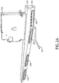
- FIGS. 3A-3B perspective views of a chiller 300 and air inlet duct 302 including embodiments of the inventive concepts disclosed herein are shown.
- a chiller 300 When a chiller 300 is operating in a defrost cycle, condensate from the chiller 300 is discharged via an air inlet in the bottom of the chiller 300 to drip into the air inlet duct 302 and be disposed of by a condensate hose 304 that drains the condensate into a waste water system.
- the air inlet duct 302 requires one or more air return ports 306, 308 to draw outside air into the chiller 300 during a chilling cycle and allow air to escape when operating in a defrost cycle.
- the air return ports 306, 308 include at least one biasable air return port 306, and may include one or more open air return ports 308.
- the open air return ports 308 may be completely open or may include a mesh configured to allow air to pass through but prevent intrusion by insects; or they may include a filtration system to prevent dust intrusion.
- airflow may be balanced across air return ports 306, 308, either in a chilling cycle or defrost cycle, via a baffle plate 310 disposed within the air inlet duct, below the chiller 300.
- the air inlet duct 302 comprises a slanted surface 312 configured to act as a condensate collector by generally angling the condensate hose 304.
- the biasable air return ports may also comprise a mesh to prevent bug intrusion when in an open orientation.
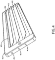
- An air return duct grille 400 includes articulated slats 402 configured to articulate about a corresponding pivot point 404.
- the air return duct grille 400 is disposed and oriented such that the articulated slates 402 articulate into an open orientation when the chiller is operating in a chilling cycle, drawing air into the air inlet and reducing the air pressure within air inlet duct.
- the articulated slats 402 articulate solely based on airflow due to the disparity in air pressure.
- the articulated slats 402 are actively biased in an open orientation.
- the articulated slats 402 form a generally continuous surface when in a closed orientation to allow condensate to flow over the closed articulated slats 402 toward a condensate hose.
- the air return duct grille 400 is disposed within the corresponding inlet duct at an angle such that condensate moves via gravity toward the condensate hose; for example, the air return duct grille 400 may be disposed in an angled surface of the inlet duct.
- the generally continuous surface is disposed to protrude from internal surface of the inlet duct sufficiently to prevent draining condensate from pooling near the air return duct grille 400.
- the articulated slats 402 are maintained in a closed orientation via gravity, air flow, and an air pressure disparity generated from the air inlet of a chiller during a defrost cycle. In at least one embodiment, the articulated slats 402 are actively biased into a closed position.
- each articulated slat 402 overlaps with the next lower articulated slat 402 to create a fluid seal.
- the air return duct grille 400 may be installed with the articulated slats 402 generally disposed vertically if installed in a surface other than a slanted surface directly below the chiller.
- each articulated slat 502 includes a slat weight 506 to bias the articulated slat 502 into a closed orientation.
- the slat weight 506 may be defined by the average air pressure disparity inside and outside the air inlet duct during a defrost cycle.
- the range of articulation of the articulated slats 502 is defined by at least one angle restrictor 508.
- the angle restrictor 508 prevents the articulated slats 502 from opening beyond a predefined point were the articulated slats 502 could pass a threshold where the articulated slats 502 would no longer close during normal operation.
Landscapes
- Engineering & Computer Science (AREA)
- General Engineering & Computer Science (AREA)
- Mechanical Engineering (AREA)
- Aviation & Aerospace Engineering (AREA)
- Chemical & Material Sciences (AREA)
- Combustion & Propulsion (AREA)
- Physics & Mathematics (AREA)
- Thermal Sciences (AREA)
- Pulmonology (AREA)
- General Health & Medical Sciences (AREA)
- Health & Medical Sciences (AREA)
- Cold Air Circulating Systems And Constructional Details In Refrigerators (AREA)
- Duct Arrangements (AREA)
- Heat-Exchange Devices With Radiators And Conduit Assemblies (AREA)
Abstract
Description
- In many commercial passenger aircraft galleys with chilled trolley compartments, cold air is supplied by either a vapour cycle air-chiller or a cold liquid supplied air cooling unit. During cooling, moisture condenses on the evaporator and/or heat exchanger. Where food storage regulations require the trolley compartment temperatures to be maintained between 0°C (32°F) and 4°C (39.2°F), the will freeze, significantly restricting air flow through the chiller.
- To defrost the heat exchanger and clear the excess moisture, the direction of the circulated air is reversed (and sometimes the cooling medium is reversed in the heat exchanger) and the moisture is blown out as condensate to be drained away into the aircraft's waste water system.
- The effectiveness of reversing the airflow depends on the type of chilling unit, its location in relation to the galley structure, and the chilled air distribution ductwork design. Air cooling units designed to be installed within the trolley compartment, usually on the back wall of a double bay together with the air distribution ductwork, cannot use drip trays to dispose of condensate because placing a drip tray directly below the heat exchanger to collect the condensate would severely restrict airflow. In those cases, return air ductwork collects any water discharged during defrost; however, when airflow is reversed, water droplets can be ejected from the air inlet grilles of the return air ductwork that is then re-ingested during the next chilling cycle.
- The increasing volume of moisture in a chilled compartment may exceed the capacity of the condensate drainage system to remove it in a single defrost cycle resulting in pooled water within the trolley compartments.
- In one aspect, embodiments of the inventive concepts disclosed herein are directed to an air return duct and air return duct grille for a chiller in an aircraft galley having articulated slats that are biased to open during chilling cycles and close during defrost cycles. In the closed orientation, the articulated slats divert any condensate from the chiller to a collection hose; in the open orientation, the articulated slates allow unrestricted airflow.
- In a further aspect, the articulated slats include a passive biasing element to bias the articulated slats into an open or closed orientation as necessary.
- In a further aspect, the air return duct also includes air return duct grills without articulated slates to allow unobstructed air flow when the articulated slats are in a closed orientation.
- It is to be understood that both the foregoing general description and the following detailed description are exemplary and explanatory only and should not restrict the scope of the claims. The accompanying drawings, which are incorporated in and constitute a part of the specification, illustrate exemplary embodiments of the inventive concepts disclosed herein and together with the general description, serve to explain the principles.
- The numerous advantages of the embodiments of the inventive concepts disclosed herein may be better understood by those skilled in the art by reference to the accompanying figures in which:
-
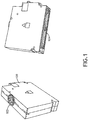
FIG. 1 shows perspective views of a chiller useful with embodiments of the inventive concepts disclosed herein; -
FIG. 2A shows a perspective view of a galley cart bay including embodiments of the inventive concepts disclosed herein; -
FIG. 2B shows a perspective view of a galley cart bay including embodiments of the inventive concepts disclosed herein; -
FIG. 3A shows a perspective view of a chiller and air inlet duct including embodiments of the inventive concepts disclosed herein; -
FIG. 3B shows a perspective view of a chiller and air inlet duct including embodiments of the inventive concepts disclosed herein; -
FIG. 4 shows a perspective view of an air return duct grille according to an exemplary embodiment of the inventive concepts disclosed herein; -
FIG. 5 shows a partial perspective view of an air return duct grille according to an exemplary embodiment of the inventive concepts disclosed herein; - Before explaining at least one embodiment of the inventive concepts disclosed herein in detail, it is to be understood that the inventive concepts are not limited in their application to the details of construction and the arrangement of the components or steps or methodologies set forth in the following description or illustrated in the drawings. In the following detailed description of embodiments of the instant inventive concepts, numerous specific details are set forth in order to provide a more thorough understanding of the inventive concepts. However, it will be apparent to one of ordinary skill in the art having the benefit of the instant disclosure that the inventive concepts disclosed herein may be practiced without these specific details. In other instances, well-known features may not be described in detail to avoid unnecessarily complicating the instant disclosure. The inventive concepts disclosed herein are capable of other embodiments or of being practiced or carried out in various ways. Also, it is to be understood that the phraseology and terminology employed herein is for the purpose of description and should not be regarded as limiting.
- As used herein a letter following a reference numeral is intended to reference an embodiment of the feature or element that may be similar, but not necessarily identical, to a previously described element or feature bearing the same reference numeral (e.g., 1, 1a, 1b). Such shorthand notations are used for purposes of convenience only, and should not be construed to limit the inventive concepts disclosed herein in any way unless expressly stated to the contrary.
- Further, unless expressly stated to the contrary, "or" refers to an inclusive or and not to an exclusive or. For example, a condition A or B is satisfied by anyone of the following: A is true (or present) and B is false (or not present), A is false (or not present) and B is true (or present), and both A and B are true (or present).
- In addition, use of the "a" or "an" are employed to describe elements and components of embodiments of the instant inventive concepts. This is done merely for convenience and to give a general sense of the inventive concepts, and "a" and "an" are intended to include one or at least one and the singular also includes the plural unless it is obvious that it is meant otherwise.
- Finally, as used herein any reference to "one embodiment," or "some embodiments" means that a particular element, feature, structure, or characteristic described in connection with the embodiment is included in at least one embodiment of the inventive concepts disclosed herein. The appearances of the phrase "in some embodiments" in various places in the specification are not necessarily all referring to the same embodiment, and embodiments of the inventive concepts disclosed may include one or more of the features expressly described or inherently present herein, or any combination of sub-combination of two or more such features, along with any other features which may not necessarily be expressly described or inherently present in the instant disclosure.
- Broadly, embodiments of the inventive concepts disclosed herein are directed to an air return duct and air return duct grille for a chiller in an aircraft galley having articulated slats that are biased to open during chilling cycles and close during defrost cycles. In the closed orientation, the articulated slats divert any condensate from the chiller to a collection hose; in the open orientation, the articulated slates allow unrestricted airflow.
- Referring to
FIG. 1 , perspective views of achiller 100 useful with embodiments of the inventive concepts disclosed herein is shown. Thechiller 100 includes anair outlet 102 disposed on a top surface and anair inlet 104 disposed on a bottom surface. During normal operation, thechiller 100 may operate in a chilling cycle where air is drawn in through theair inlet 104, cooled within thechiller 100, and expelled from theair outlet 102 to cool the surrounding space or any area where the cooled air is ducted. In a defrost cycle, air flow is reversed so that air is drawn in through theair outlet 102 and expelled through theair inlet 104. Because frost buildup within thechiller 100 comes from ambient moisture, the air drawn back in through theair outlet 102 during the defrost cycle is generally dryer than the air that originally caused frost buildup and so does not contribute significantly to frost buildup. At least some of the condensate melted from the heat exchanger within thechiller 100 drips out of theair inlet 104 as theair inlet 104 is disposed on the bottom surface. - Referring to
FIGS. 2A-2B , perspective views of agalley cart bay 200 including embodiments of the inventive concepts disclosed herein are shown. Thegalley cart bay 200, adapted for chilled carts, comprises a chilledair outlet duct 202 having anoutlet connection point 204 adapted to connect to the air outlet of a chiller; and defining one or moreair supply outlets 206. Thegalley cart bay 200 also comprises aninlet duct 208 having anair inlet duct 208 having aninlet connection point 210 adapted to connect to the air inlet of the chiller. - The
air inlet duct 208 defines one or more biasable chilledair return ports 212 disposed below theinlet connection point 210. In at least one embodiment, theair inlet duct 208 also defines one or more open chilledair return ports 214 disposed distal from theinlet connection point 210. - Referring to
FIGS. 3A-3B , perspective views of achiller 300 andair inlet duct 302 including embodiments of the inventive concepts disclosed herein are shown. When achiller 300 is operating in a defrost cycle, condensate from thechiller 300 is discharged via an air inlet in the bottom of thechiller 300 to drip into theair inlet duct 302 and be disposed of by acondensate hose 304 that drains the condensate into a waste water system. Theair inlet duct 302 requires one or moreair return ports chiller 300 during a chilling cycle and allow air to escape when operating in a defrost cycle. - The
air return ports air return port 306, and may include one or more openair return ports 308. The biasableair return ports 306, disposed beneath thechiller 300 and in line with a path of condensate dripping from thechiller 300 during a defrost cycle, include air return duct grills as described here. The openair return ports 308 may be completely open or may include a mesh configured to allow air to pass through but prevent intrusion by insects; or they may include a filtration system to prevent dust intrusion. - In at least one embodiment, airflow may be balanced across air return
ports baffle plate 310 disposed within the air inlet duct, below thechiller 300. - In at least one embodiment, the
air inlet duct 302 comprises aslanted surface 312 configured to act as a condensate collector by generally angling thecondensate hose 304. - In at least one embodiment, the biasable air return ports may also comprise a mesh to prevent bug intrusion when in an open orientation.
- Referring to
FIG. 4 , a perspective view of an airreturn duct grille 400 according to an exemplary embodiment of the inventive concepts disclosed herein is shown. An air returnduct grille 400 includes articulatedslats 402 configured to articulate about acorresponding pivot point 404. When installed in an inlet duct, the airreturn duct grille 400 is disposed and oriented such that the articulatedslates 402 articulate into an open orientation when the chiller is operating in a chilling cycle, drawing air into the air inlet and reducing the air pressure within air inlet duct. In at least one embodiment, the articulatedslats 402 articulate solely based on airflow due to the disparity in air pressure. In at least one embodiment, the articulatedslats 402 are actively biased in an open orientation. - In at least one embodiment, the articulated
slats 402 form a generally continuous surface when in a closed orientation to allow condensate to flow over the closed articulatedslats 402 toward a condensate hose. In at least one embodiment, the airreturn duct grille 400 is disposed within the corresponding inlet duct at an angle such that condensate moves via gravity toward the condensate hose; for example, the airreturn duct grille 400 may be disposed in an angled surface of the inlet duct. Furthermore, the generally continuous surface is disposed to protrude from internal surface of the inlet duct sufficiently to prevent draining condensate from pooling near the airreturn duct grille 400. - In at least one embodiment, the articulated
slats 402 are maintained in a closed orientation via gravity, air flow, and an air pressure disparity generated from the air inlet of a chiller during a defrost cycle. In at least one embodiment, the articulatedslats 402 are actively biased into a closed position. - In at least one embodiment, each articulated
slat 402 overlaps with the next lower articulatedslat 402 to create a fluid seal. Agasket 406 disposed near the top of the airreturn duct grille 400 to create a fluid seal at an upper portion of the top-most articulatedslat 402. - While embodiments shown herein generally show the air
return duct grille 400 installed with the articulatedslats 402 running horizontally, it is envisioned that the airreturn duct grille 400 may be installed with the articulatedslats 402 generally disposed vertically if installed in a surface other than a slanted surface directly below the chiller. - Referring to
FIG. 5 , a partial perspective view of an airreturn duct grille 500 according to an exemplary embodiment of the inventive concepts disclosed herein is shown. The air returnduct grille 500 includes a plurality of articulatedslats 502, each configured to articulate about acorresponding pivot point 504. In at least one embodiment, each articulatedslat 502 includes aslat weight 506 to bias the articulatedslat 502 into a closed orientation. Theslat weight 506 may be defined by the average air pressure disparity inside and outside the air inlet duct during a defrost cycle. - In at least one embodiment, the range of articulation of the articulated
slats 502 is defined by at least oneangle restrictor 508. The angle restrictor 508 prevents the articulatedslats 502 from opening beyond a predefined point were the articulatedslats 502 could pass a threshold where the articulatedslats 502 would no longer close during normal operation. - It is believed that the inventive concepts disclosed herein and many of their attendant advantages will be understood by the foregoing description of embodiments of the inventive concepts disclosed, and it will be apparent that various changes may be made in the form, construction, and arrangement of the components thereof without departing from the broad scope of the inventive concepts disclosed herein or without sacrificing all of their material advantages; and individual features from various embodiments may be combined to arrive at other embodiments. The form herein before described being merely an explanatory embodiment thereof, it is the intention of the following claims to encompass and include such changes. Furthermore, any of the features disclosed in relation to any of the individual embodiments may be incorporated into any other embodiment.
Claims (14)
- An air return duct comprising:a slanted surface (312) configured to slant toward a condensate hose (304); andat least one grille (400;500) comprising a plurality of partially overlapping articulated slats (402;502) configured to produce a fluid seal when in a closed orientation disposed in the slanted surface,wherein:the articulated slats are biased into a closed orientation when an air pressure disparity inside the air return duct and outside the air return duct is below a threshold; andthe articulated slats are configured to an open orientation when the air pressure disparity inside the air return duct and outside the air return duct is above the threshold.
- The air return duct of claim 1, wherein the at least one grille further comprises at least one angle restrictor (508) configured to define a maximum deflection of at least one articulated slat when in the open orientation.
- The air return duct of claim 1 or 2, further comprising at least one slant weight disposed on each of the articulated slats configured to bias the corresponding articulated slat into a closed orientation.
- The air return duct of any preceding claim, further comprising an insect mesh.
- The air return duct of any preceding claim, further comprising at least one open air inlet port disposed in the slanted surface, distal from an inlet connection port defined by the air return duct.
- The air return duct of claim 5, further comprising a baffle (310) disposed between the at least one grille and the inlet port.
- The air return duct of any preceding claim, wherein the at least one grille further comprises a gasket (406) disposed proximal to an articulated edge of an upper-most articulated slat.
- The air return duct of any preceding claim, further comprising a biasing spring configured to bias the articulated slats into a closed orientation.
- An aircraft galley comprising:a chilled air outlet duct (202) defining an outlet connection point;the air return duct of any preceding claim, the air return duct defining an inlet connection pointa chiller (100) disposed between the outlet connection point and inlet connection point; anda condensate hose (304) connected to the air return duct and an aircraft waste water system.
- An air return duct grille (400;500) comprising:a plurality of partially overlapping articulated slats (402;502) configured to produce a fluid seal when in a closed orientation; andat least one angle restrictor (508) configured to define a maximum deflection of at least one articulated slat when in an open orientation.
- The air return duct grille of claim 10, further comprising at least one slant weight disposed on each of the articulated slats configured to bias the corresponding articulated slat into a closed orientation.
- The air return duct grille of claim 10 or 11, further comprising an insect mesh.
- The air return duct grille of claim 10, 11, or 12, further comprising a gasket (406) disposed proximal to an articulated edge of an upper-most articulated slat.
- The air return duct grille of any of claims 10 to 13, further comprising a biasing spring configured to bias the articulated slats into a closed orientation.
Applications Claiming Priority (1)
| Application Number | Priority Date | Filing Date | Title |
|---|---|---|---|
| US16/571,682 US12377988B2 (en) | 2019-09-16 | 2019-09-16 | Managing condensate drainage within chilled air ductwork |
Publications (2)
| Publication Number | Publication Date |
|---|---|
| EP3792181A1 true EP3792181A1 (en) | 2021-03-17 |
| EP3792181B1 EP3792181B1 (en) | 2023-10-18 |
Family
ID=68917459
Family Applications (1)
| Application Number | Title | Priority Date | Filing Date |
|---|---|---|---|
| EP19216314.5A Active EP3792181B1 (en) | 2019-09-16 | 2019-12-13 | Managing condensate drainage within chilled air ductwork background |
Country Status (3)
| Country | Link |
|---|---|
| US (1) | US12377988B2 (en) |
| EP (1) | EP3792181B1 (en) |
| CN (1) | CN112503963B (en) |
Citations (6)
| Publication number | Priority date | Publication date | Assignee | Title |
|---|---|---|---|---|
| US2299833A (en) * | 1940-05-20 | 1942-10-27 | John Spargo | Louver mechanism for attic ventilation |
| JPH094916A (en) * | 1995-06-20 | 1997-01-10 | Toshiba Ave Corp | Indoor unit of air conditioner |
| US20150059378A1 (en) * | 2013-08-30 | 2015-03-05 | B/E Aerospace, Inc. | Device for reversing chiller airflow in an aircraft galley |
| GB2522040A (en) * | 2014-01-10 | 2015-07-15 | Lewis Peters | Duct assembly |
| US20160007736A1 (en) * | 2014-07-08 | 2016-01-14 | B/E Aerospace, Inc. | Compact liquid cooled, air through galley chiller |
| US20180093774A1 (en) * | 2015-06-03 | 2018-04-05 | Airbus Operations Gmbh | Cooling system for a galley, and method of operating such a cooling system |
Family Cites Families (14)
| Publication number | Priority date | Publication date | Assignee | Title |
|---|---|---|---|---|
| JPH11141905A (en) * | 1997-11-06 | 1999-05-28 | Fujitsu General Ltd | Air conditioner |
| US6880351B2 (en) * | 2001-09-05 | 2005-04-19 | Be Intellectual Property, Inc. | Liquid galley refrigeration system for aircraft |
| FR2962201B1 (en) * | 2010-07-02 | 2014-02-28 | France Etat | HEAT EXCHANGER WITH INTERNAL FEED AND RETURN TUBES |
| WO2013033439A1 (en) * | 2011-08-30 | 2013-03-07 | B/E Aerospace, Inc. | Reconfigurable chilled air outlet for an aircraft galley chiller |
| US20140014436A1 (en) * | 2012-07-12 | 2014-01-16 | B/E Aerospace, Inc. | Noise-Reducing Air Inlet Grille for an Appliance |
| US8936671B2 (en) | 2013-02-22 | 2015-01-20 | The Boeing Company | Aircraft cabin air entrainment filtration with condensation drain |
| US9157683B2 (en) * | 2013-04-02 | 2015-10-13 | Hamilton Sundstrand Corporation | Heat exchanger for aircraft application |
| US10029798B2 (en) * | 2014-03-31 | 2018-07-24 | The Boeing Company | Structure and method for reducing air flow in a wall volume of an aircraft |
| US20170122647A1 (en) * | 2014-07-08 | 2017-05-04 | B/E Aerospace, Inc. | Compact liquid cooled, air through galley chiller |
| DE102015200111A1 (en) * | 2015-01-08 | 2016-07-14 | Airbus Operations Gmbh | Cooling system with a water separator and method of operating a cooling system |
| US20170370630A1 (en) * | 2015-01-28 | 2017-12-28 | Sell Gmbh | Method and apparatus for cooling a chilled-goods container |
| US10492603B2 (en) * | 2015-05-19 | 2019-12-03 | The Boeing Company | Systems and methods of cooling a galley of an aircraft |
| DE102015210271A1 (en) * | 2015-06-03 | 2016-12-08 | Airbus Operations Gmbh | Trolley compartment and galley |
| CN106767109B (en) * | 2017-01-18 | 2024-04-26 | 中国海洋石油集团有限公司 | A fluid uniform distribution guide device and a wound tube heat exchanger having the same |
-
2019
- 2019-09-16 US US16/571,682 patent/US12377988B2/en active Active
- 2019-12-13 EP EP19216314.5A patent/EP3792181B1/en active Active
-
2020
- 2020-01-16 CN CN202010056932.3A patent/CN112503963B/en active Active
Patent Citations (6)
| Publication number | Priority date | Publication date | Assignee | Title |
|---|---|---|---|---|
| US2299833A (en) * | 1940-05-20 | 1942-10-27 | John Spargo | Louver mechanism for attic ventilation |
| JPH094916A (en) * | 1995-06-20 | 1997-01-10 | Toshiba Ave Corp | Indoor unit of air conditioner |
| US20150059378A1 (en) * | 2013-08-30 | 2015-03-05 | B/E Aerospace, Inc. | Device for reversing chiller airflow in an aircraft galley |
| GB2522040A (en) * | 2014-01-10 | 2015-07-15 | Lewis Peters | Duct assembly |
| US20160007736A1 (en) * | 2014-07-08 | 2016-01-14 | B/E Aerospace, Inc. | Compact liquid cooled, air through galley chiller |
| US20180093774A1 (en) * | 2015-06-03 | 2018-04-05 | Airbus Operations Gmbh | Cooling system for a galley, and method of operating such a cooling system |
Also Published As
| Publication number | Publication date |
|---|---|
| CN112503963A (en) | 2021-03-16 |
| CN112503963B (en) | 2025-03-18 |
| EP3792181B1 (en) | 2023-10-18 |
| US12377988B2 (en) | 2025-08-05 |
| US20210323682A1 (en) | 2021-10-21 |
Similar Documents
| Publication | Publication Date | Title |
|---|---|---|
| US5499514A (en) | Defrost water drain system for a refrigerator | |
| CA2870456C (en) | Louver device for removing moisture and dust | |
| US8647183B2 (en) | Air curtain system for a refrigerated case | |
| EP3205950B1 (en) | Air conditioner with condensate collection device | |
| CN109990529B (en) | refrigerator | |
| CN107031491B (en) | Cooling device | |
| US20070289323A1 (en) | Refrigerated case with low frost operation | |
| DE102012209938A1 (en) | The refrigerator | |
| JP2018054201A6 (en) | Duct fan module and cooling unit using the same | |
| JP2018054201A (en) | Duct fan module and cooling unit using the same | |
| US12377988B2 (en) | Managing condensate drainage within chilled air ductwork | |
| CN112298575B (en) | Air cooler for confined spaces | |
| DK177870B1 (en) | A cooling unit for a climatized cabinet | |
| JP6796797B2 (en) | Showcase and control device | |
| JP2003146070A (en) | Moving refrigeration unit | |
| JP2007046892A (en) | refrigerator | |
| JP2001108351A (en) | Refrigerator | |
| EP3699527B1 (en) | Entrance refrigerator | |
| JP2009275929A (en) | Refrigerator | |
| EP3699526B1 (en) | Entrance refrigerator | |
| CN220624499U (en) | Refrigerator with a refrigerator body | |
| CN107062748A (en) | Refrigerator | |
| EP2373200B1 (en) | Refrigerated case defrost water evaporation | |
| JPH08136107A (en) | Cold air circulation showcase | |
| CN215002489U (en) | Air duct plate assembly of refrigeration equipment and refrigeration equipment with same |
Legal Events
| Date | Code | Title | Description |
|---|---|---|---|
| PUAI | Public reference made under article 153(3) epc to a published international application that has entered the european phase |
Free format text: ORIGINAL CODE: 0009012 |
|
| STAA | Information on the status of an ep patent application or granted ep patent |
Free format text: STATUS: THE APPLICATION HAS BEEN PUBLISHED |
|
| AK | Designated contracting states |
Kind code of ref document: A1 Designated state(s): AL AT BE BG CH CY CZ DE DK EE ES FI FR GB GR HR HU IE IS IT LI LT LU LV MC MK MT NL NO PL PT RO RS SE SI SK SM TR |
|
| AX | Request for extension of the european patent |
Extension state: BA ME |
|
| STAA | Information on the status of an ep patent application or granted ep patent |
Free format text: STATUS: REQUEST FOR EXAMINATION WAS MADE |
|
| 17P | Request for examination filed |
Effective date: 20210915 |
|
| RBV | Designated contracting states (corrected) |
Designated state(s): AL AT BE BG CH CY CZ DE DK EE ES FI FR GB GR HR HU IE IS IT LI LT LU LV MC MK MT NL NO PL PT RO RS SE SI SK SM TR |
|
| STAA | Information on the status of an ep patent application or granted ep patent |
Free format text: STATUS: EXAMINATION IS IN PROGRESS |
|
| 17Q | First examination report despatched |
Effective date: 20220126 |
|
| RIC1 | Information provided on ipc code assigned before grant |
Ipc: B64D 11/00 20060101ALN20230405BHEP Ipc: B64D 13/06 20060101ALN20230405BHEP Ipc: B64D 11/04 20060101AFI20230405BHEP |
|
| GRAP | Despatch of communication of intention to grant a patent |
Free format text: ORIGINAL CODE: EPIDOSNIGR1 |
|
| STAA | Information on the status of an ep patent application or granted ep patent |
Free format text: STATUS: GRANT OF PATENT IS INTENDED |
|
| RIC1 | Information provided on ipc code assigned before grant |
Ipc: B64D 11/00 20060101ALN20230502BHEP Ipc: B64D 13/06 20060101ALN20230502BHEP Ipc: B64D 11/04 20060101AFI20230502BHEP |
|
| INTG | Intention to grant announced |
Effective date: 20230519 |
|
| GRAS | Grant fee paid |
Free format text: ORIGINAL CODE: EPIDOSNIGR3 |
|
| GRAA | (expected) grant |
Free format text: ORIGINAL CODE: 0009210 |
|
| STAA | Information on the status of an ep patent application or granted ep patent |
Free format text: STATUS: THE PATENT HAS BEEN GRANTED |
|
| AK | Designated contracting states |
Kind code of ref document: B1 Designated state(s): AL AT BE BG CH CY CZ DE DK EE ES FI FR GB GR HR HU IE IS IT LI LT LU LV MC MK MT NL NO PL PT RO RS SE SI SK SM TR |
|
| REG | Reference to a national code |
Ref country code: GB Ref legal event code: FG4D |
|
| REG | Reference to a national code |
Ref country code: CH Ref legal event code: EP |
|
| P01 | Opt-out of the competence of the unified patent court (upc) registered |
Effective date: 20230922 |
|
| REG | Reference to a national code |
Ref country code: IE Ref legal event code: FG4D |
|
| REG | Reference to a national code |
Ref country code: DE Ref legal event code: R096 Ref document number: 602019039515 Country of ref document: DE |
|
| REG | Reference to a national code |
Ref country code: LT Ref legal event code: MG9D |
|
| REG | Reference to a national code |
Ref country code: NL Ref legal event code: MP Effective date: 20231018 |
|
| REG | Reference to a national code |
Ref country code: AT Ref legal event code: MK05 Ref document number: 1622238 Country of ref document: AT Kind code of ref document: T Effective date: 20231018 |
|
| PG25 | Lapsed in a contracting state [announced via postgrant information from national office to epo] |
Ref country code: NL Free format text: LAPSE BECAUSE OF FAILURE TO SUBMIT A TRANSLATION OF THE DESCRIPTION OR TO PAY THE FEE WITHIN THE PRESCRIBED TIME-LIMIT Effective date: 20231018 |
|
| PG25 | Lapsed in a contracting state [announced via postgrant information from national office to epo] |
Ref country code: GR Free format text: LAPSE BECAUSE OF FAILURE TO SUBMIT A TRANSLATION OF THE DESCRIPTION OR TO PAY THE FEE WITHIN THE PRESCRIBED TIME-LIMIT Effective date: 20240119 |
|
| PG25 | Lapsed in a contracting state [announced via postgrant information from national office to epo] |
Ref country code: IS Free format text: LAPSE BECAUSE OF FAILURE TO SUBMIT A TRANSLATION OF THE DESCRIPTION OR TO PAY THE FEE WITHIN THE PRESCRIBED TIME-LIMIT Effective date: 20240218 |
|
| PG25 | Lapsed in a contracting state [announced via postgrant information from national office to epo] |
Ref country code: LT Free format text: LAPSE BECAUSE OF FAILURE TO SUBMIT A TRANSLATION OF THE DESCRIPTION OR TO PAY THE FEE WITHIN THE PRESCRIBED TIME-LIMIT Effective date: 20231018 |
|
| PG25 | Lapsed in a contracting state [announced via postgrant information from national office to epo] |
Ref country code: AT Free format text: LAPSE BECAUSE OF FAILURE TO SUBMIT A TRANSLATION OF THE DESCRIPTION OR TO PAY THE FEE WITHIN THE PRESCRIBED TIME-LIMIT Effective date: 20231018 |
|
| PG25 | Lapsed in a contracting state [announced via postgrant information from national office to epo] |
Ref country code: ES Free format text: LAPSE BECAUSE OF FAILURE TO SUBMIT A TRANSLATION OF THE DESCRIPTION OR TO PAY THE FEE WITHIN THE PRESCRIBED TIME-LIMIT Effective date: 20231018 |
|
| PG25 | Lapsed in a contracting state [announced via postgrant information from national office to epo] |
Ref country code: LT Free format text: LAPSE BECAUSE OF FAILURE TO SUBMIT A TRANSLATION OF THE DESCRIPTION OR TO PAY THE FEE WITHIN THE PRESCRIBED TIME-LIMIT Effective date: 20231018 Ref country code: IS Free format text: LAPSE BECAUSE OF FAILURE TO SUBMIT A TRANSLATION OF THE DESCRIPTION OR TO PAY THE FEE WITHIN THE PRESCRIBED TIME-LIMIT Effective date: 20240218 Ref country code: GR Free format text: LAPSE BECAUSE OF FAILURE TO SUBMIT A TRANSLATION OF THE DESCRIPTION OR TO PAY THE FEE WITHIN THE PRESCRIBED TIME-LIMIT Effective date: 20240119 Ref country code: ES Free format text: LAPSE BECAUSE OF FAILURE TO SUBMIT A TRANSLATION OF THE DESCRIPTION OR TO PAY THE FEE WITHIN THE PRESCRIBED TIME-LIMIT Effective date: 20231018 Ref country code: BG Free format text: LAPSE BECAUSE OF FAILURE TO SUBMIT A TRANSLATION OF THE DESCRIPTION OR TO PAY THE FEE WITHIN THE PRESCRIBED TIME-LIMIT Effective date: 20240118 Ref country code: AT Free format text: LAPSE BECAUSE OF FAILURE TO SUBMIT A TRANSLATION OF THE DESCRIPTION OR TO PAY THE FEE WITHIN THE PRESCRIBED TIME-LIMIT Effective date: 20231018 Ref country code: PT Free format text: LAPSE BECAUSE OF FAILURE TO SUBMIT A TRANSLATION OF THE DESCRIPTION OR TO PAY THE FEE WITHIN THE PRESCRIBED TIME-LIMIT Effective date: 20240219 |
|
| PG25 | Lapsed in a contracting state [announced via postgrant information from national office to epo] |
Ref country code: SE Free format text: LAPSE BECAUSE OF FAILURE TO SUBMIT A TRANSLATION OF THE DESCRIPTION OR TO PAY THE FEE WITHIN THE PRESCRIBED TIME-LIMIT Effective date: 20231018 Ref country code: RS Free format text: LAPSE BECAUSE OF FAILURE TO SUBMIT A TRANSLATION OF THE DESCRIPTION OR TO PAY THE FEE WITHIN THE PRESCRIBED TIME-LIMIT Effective date: 20231018 Ref country code: PL Free format text: LAPSE BECAUSE OF FAILURE TO SUBMIT A TRANSLATION OF THE DESCRIPTION OR TO PAY THE FEE WITHIN THE PRESCRIBED TIME-LIMIT Effective date: 20231018 Ref country code: NO Free format text: LAPSE BECAUSE OF FAILURE TO SUBMIT A TRANSLATION OF THE DESCRIPTION OR TO PAY THE FEE WITHIN THE PRESCRIBED TIME-LIMIT Effective date: 20240118 Ref country code: LV Free format text: LAPSE BECAUSE OF FAILURE TO SUBMIT A TRANSLATION OF THE DESCRIPTION OR TO PAY THE FEE WITHIN THE PRESCRIBED TIME-LIMIT Effective date: 20231018 Ref country code: HR Free format text: LAPSE BECAUSE OF FAILURE TO SUBMIT A TRANSLATION OF THE DESCRIPTION OR TO PAY THE FEE WITHIN THE PRESCRIBED TIME-LIMIT Effective date: 20231018 |
|
| PG25 | Lapsed in a contracting state [announced via postgrant information from national office to epo] |
Ref country code: DK Free format text: LAPSE BECAUSE OF FAILURE TO SUBMIT A TRANSLATION OF THE DESCRIPTION OR TO PAY THE FEE WITHIN THE PRESCRIBED TIME-LIMIT Effective date: 20231018 |
|
| REG | Reference to a national code |
Ref country code: DE Ref legal event code: R097 Ref document number: 602019039515 Country of ref document: DE |
|
| PG25 | Lapsed in a contracting state [announced via postgrant information from national office to epo] |
Ref country code: CZ Free format text: LAPSE BECAUSE OF FAILURE TO SUBMIT A TRANSLATION OF THE DESCRIPTION OR TO PAY THE FEE WITHIN THE PRESCRIBED TIME-LIMIT Effective date: 20231018 |
|
| PG25 | Lapsed in a contracting state [announced via postgrant information from national office to epo] |
Ref country code: SK Free format text: LAPSE BECAUSE OF FAILURE TO SUBMIT A TRANSLATION OF THE DESCRIPTION OR TO PAY THE FEE WITHIN THE PRESCRIBED TIME-LIMIT Effective date: 20231018 |
|
| PG25 | Lapsed in a contracting state [announced via postgrant information from national office to epo] |
Ref country code: SM Free format text: LAPSE BECAUSE OF FAILURE TO SUBMIT A TRANSLATION OF THE DESCRIPTION OR TO PAY THE FEE WITHIN THE PRESCRIBED TIME-LIMIT Effective date: 20231018 Ref country code: SK Free format text: LAPSE BECAUSE OF FAILURE TO SUBMIT A TRANSLATION OF THE DESCRIPTION OR TO PAY THE FEE WITHIN THE PRESCRIBED TIME-LIMIT Effective date: 20231018 Ref country code: RO Free format text: LAPSE BECAUSE OF FAILURE TO SUBMIT A TRANSLATION OF THE DESCRIPTION OR TO PAY THE FEE WITHIN THE PRESCRIBED TIME-LIMIT Effective date: 20231018 Ref country code: IT Free format text: LAPSE BECAUSE OF FAILURE TO SUBMIT A TRANSLATION OF THE DESCRIPTION OR TO PAY THE FEE WITHIN THE PRESCRIBED TIME-LIMIT Effective date: 20231018 Ref country code: EE Free format text: LAPSE BECAUSE OF FAILURE TO SUBMIT A TRANSLATION OF THE DESCRIPTION OR TO PAY THE FEE WITHIN THE PRESCRIBED TIME-LIMIT Effective date: 20231018 Ref country code: DK Free format text: LAPSE BECAUSE OF FAILURE TO SUBMIT A TRANSLATION OF THE DESCRIPTION OR TO PAY THE FEE WITHIN THE PRESCRIBED TIME-LIMIT Effective date: 20231018 Ref country code: CZ Free format text: LAPSE BECAUSE OF FAILURE TO SUBMIT A TRANSLATION OF THE DESCRIPTION OR TO PAY THE FEE WITHIN THE PRESCRIBED TIME-LIMIT Effective date: 20231018 |
|
| REG | Reference to a national code |
Ref country code: CH Ref legal event code: PL |
|
| PLBE | No opposition filed within time limit |
Free format text: ORIGINAL CODE: 0009261 |
|
| STAA | Information on the status of an ep patent application or granted ep patent |
Free format text: STATUS: NO OPPOSITION FILED WITHIN TIME LIMIT |
|
| PG25 | Lapsed in a contracting state [announced via postgrant information from national office to epo] |
Ref country code: LU Free format text: LAPSE BECAUSE OF NON-PAYMENT OF DUE FEES Effective date: 20231213 |
|
| PG25 | Lapsed in a contracting state [announced via postgrant information from national office to epo] |
Ref country code: MC Free format text: LAPSE BECAUSE OF FAILURE TO SUBMIT A TRANSLATION OF THE DESCRIPTION OR TO PAY THE FEE WITHIN THE PRESCRIBED TIME-LIMIT Effective date: 20231018 |
|
| REG | Reference to a national code |
Ref country code: BE Ref legal event code: MM Effective date: 20231231 |
|
| PG25 | Lapsed in a contracting state [announced via postgrant information from national office to epo] |
Ref country code: MC Free format text: LAPSE BECAUSE OF FAILURE TO SUBMIT A TRANSLATION OF THE DESCRIPTION OR TO PAY THE FEE WITHIN THE PRESCRIBED TIME-LIMIT Effective date: 20231018 Ref country code: LU Free format text: LAPSE BECAUSE OF NON-PAYMENT OF DUE FEES Effective date: 20231213 |
|
| 26N | No opposition filed |
Effective date: 20240719 |
|
| REG | Reference to a national code |
Ref country code: IE Ref legal event code: MM4A |
|
| PG25 | Lapsed in a contracting state [announced via postgrant information from national office to epo] |
Ref country code: IE Free format text: LAPSE BECAUSE OF NON-PAYMENT OF DUE FEES Effective date: 20231213 |
|
| PG25 | Lapsed in a contracting state [announced via postgrant information from national office to epo] |
Ref country code: BE Free format text: LAPSE BECAUSE OF NON-PAYMENT OF DUE FEES Effective date: 20231231 |
|
| PG25 | Lapsed in a contracting state [announced via postgrant information from national office to epo] |
Ref country code: CH Free format text: LAPSE BECAUSE OF NON-PAYMENT OF DUE FEES Effective date: 20231231 |
|
| PG25 | Lapsed in a contracting state [announced via postgrant information from national office to epo] |
Ref country code: SI Free format text: LAPSE BECAUSE OF FAILURE TO SUBMIT A TRANSLATION OF THE DESCRIPTION OR TO PAY THE FEE WITHIN THE PRESCRIBED TIME-LIMIT Effective date: 20231018 |
|
| PG25 | Lapsed in a contracting state [announced via postgrant information from national office to epo] |
Ref country code: SI Free format text: LAPSE BECAUSE OF FAILURE TO SUBMIT A TRANSLATION OF THE DESCRIPTION OR TO PAY THE FEE WITHIN THE PRESCRIBED TIME-LIMIT Effective date: 20231018 Ref country code: IE Free format text: LAPSE BECAUSE OF NON-PAYMENT OF DUE FEES Effective date: 20231213 Ref country code: CH Free format text: LAPSE BECAUSE OF NON-PAYMENT OF DUE FEES Effective date: 20231231 Ref country code: BE Free format text: LAPSE BECAUSE OF NON-PAYMENT OF DUE FEES Effective date: 20231231 |
|
| PG25 | Lapsed in a contracting state [announced via postgrant information from national office to epo] |
Ref country code: FI Free format text: LAPSE BECAUSE OF FAILURE TO SUBMIT A TRANSLATION OF THE DESCRIPTION OR TO PAY THE FEE WITHIN THE PRESCRIBED TIME-LIMIT Effective date: 20231019 |
|
| PG25 | Lapsed in a contracting state [announced via postgrant information from national office to epo] |
Ref country code: CY Free format text: LAPSE BECAUSE OF FAILURE TO SUBMIT A TRANSLATION OF THE DESCRIPTION OR TO PAY THE FEE WITHIN THE PRESCRIBED TIME-LIMIT; INVALID AB INITIO Effective date: 20191213 |
|
| PG25 | Lapsed in a contracting state [announced via postgrant information from national office to epo] |
Ref country code: HU Free format text: LAPSE BECAUSE OF FAILURE TO SUBMIT A TRANSLATION OF THE DESCRIPTION OR TO PAY THE FEE WITHIN THE PRESCRIBED TIME-LIMIT; INVALID AB INITIO Effective date: 20191213 |
|
| PG25 | Lapsed in a contracting state [announced via postgrant information from national office to epo] |
Ref country code: TR Free format text: LAPSE BECAUSE OF FAILURE TO SUBMIT A TRANSLATION OF THE DESCRIPTION OR TO PAY THE FEE WITHIN THE PRESCRIBED TIME-LIMIT Effective date: 20231018 |
|
| PGFP | Annual fee paid to national office [announced via postgrant information from national office to epo] |
Ref country code: DE Payment date: 20251126 Year of fee payment: 7 |
|
| PGFP | Annual fee paid to national office [announced via postgrant information from national office to epo] |
Ref country code: GB Payment date: 20251119 Year of fee payment: 7 |
|
| PGFP | Annual fee paid to national office [announced via postgrant information from national office to epo] |
Ref country code: FR Payment date: 20251120 Year of fee payment: 7 |