EP3792175A1 - A thermal management system, a composite wing, and a composite wing spar - Google Patents
A thermal management system, a composite wing, and a composite wing spar Download PDFInfo
- Publication number
- EP3792175A1 EP3792175A1 EP20197832.7A EP20197832A EP3792175A1 EP 3792175 A1 EP3792175 A1 EP 3792175A1 EP 20197832 A EP20197832 A EP 20197832A EP 3792175 A1 EP3792175 A1 EP 3792175A1
- Authority
- EP
- European Patent Office
- Prior art keywords
- composite
- structural member
- heat
- heat transfer
- thermally conductive
- Prior art date
- Legal status (The legal status is an assumption and is not a legal conclusion. Google has not performed a legal analysis and makes no representation as to the accuracy of the status listed.)
- Granted
Links
Images
Classifications
-
- B—PERFORMING OPERATIONS; TRANSPORTING
- B32—LAYERED PRODUCTS
- B32B—LAYERED PRODUCTS, i.e. PRODUCTS BUILT-UP OF STRATA OF FLAT OR NON-FLAT, e.g. CELLULAR OR HONEYCOMB, FORM
- B32B7/00—Layered products characterised by the relation between layers; Layered products characterised by the relative orientation of features between layers, or by the relative values of a measurable parameter between layers, i.e. products comprising layers having different physical, chemical or physicochemical properties; Layered products characterised by the interconnection of layers
- B32B7/04—Interconnection of layers
- B32B7/08—Interconnection of layers by mechanical means
-
- B—PERFORMING OPERATIONS; TRANSPORTING
- B64—AIRCRAFT; AVIATION; COSMONAUTICS
- B64C—AEROPLANES; HELICOPTERS
- B64C3/00—Wings
- B64C3/36—Structures adapted to reduce effects of aerodynamic or other external heating
-
- B—PERFORMING OPERATIONS; TRANSPORTING
- B64—AIRCRAFT; AVIATION; COSMONAUTICS
- B64C—AEROPLANES; HELICOPTERS
- B64C3/00—Wings
- B64C3/18—Spars; Ribs; Stringers
- B64C3/182—Stringers, longerons
-
- B—PERFORMING OPERATIONS; TRANSPORTING
- B32—LAYERED PRODUCTS
- B32B—LAYERED PRODUCTS, i.e. PRODUCTS BUILT-UP OF STRATA OF FLAT OR NON-FLAT, e.g. CELLULAR OR HONEYCOMB, FORM
- B32B27/00—Layered products comprising a layer of synthetic resin
- B32B27/06—Layered products comprising a layer of synthetic resin as the main or only constituent of a layer, which is next to another layer of the same or of a different material
- B32B27/065—Layered products comprising a layer of synthetic resin as the main or only constituent of a layer, which is next to another layer of the same or of a different material of foam
-
- B—PERFORMING OPERATIONS; TRANSPORTING
- B32—LAYERED PRODUCTS
- B32B—LAYERED PRODUCTS, i.e. PRODUCTS BUILT-UP OF STRATA OF FLAT OR NON-FLAT, e.g. CELLULAR OR HONEYCOMB, FORM
- B32B5/00—Layered products characterised by the non- homogeneity or physical structure, i.e. comprising a fibrous, filamentary, particulate or foam layer; Layered products characterised by having a layer differing constitutionally or physically in different parts
- B32B5/18—Layered products characterised by the non- homogeneity or physical structure, i.e. comprising a fibrous, filamentary, particulate or foam layer; Layered products characterised by having a layer differing constitutionally or physically in different parts characterised by features of a layer of foamed material
-
- B—PERFORMING OPERATIONS; TRANSPORTING
- B32—LAYERED PRODUCTS
- B32B—LAYERED PRODUCTS, i.e. PRODUCTS BUILT-UP OF STRATA OF FLAT OR NON-FLAT, e.g. CELLULAR OR HONEYCOMB, FORM
- B32B5/00—Layered products characterised by the non- homogeneity or physical structure, i.e. comprising a fibrous, filamentary, particulate or foam layer; Layered products characterised by having a layer differing constitutionally or physically in different parts
- B32B5/22—Layered products characterised by the non- homogeneity or physical structure, i.e. comprising a fibrous, filamentary, particulate or foam layer; Layered products characterised by having a layer differing constitutionally or physically in different parts characterised by the presence of two or more layers which are next to each other and are fibrous, filamentary, formed of particles or foamed
- B32B5/24—Layered products characterised by the non- homogeneity or physical structure, i.e. comprising a fibrous, filamentary, particulate or foam layer; Layered products characterised by having a layer differing constitutionally or physically in different parts characterised by the presence of two or more layers which are next to each other and are fibrous, filamentary, formed of particles or foamed one layer being a fibrous or filamentary layer
- B32B5/245—Layered products characterised by the non- homogeneity or physical structure, i.e. comprising a fibrous, filamentary, particulate or foam layer; Layered products characterised by having a layer differing constitutionally or physically in different parts characterised by the presence of two or more layers which are next to each other and are fibrous, filamentary, formed of particles or foamed one layer being a fibrous or filamentary layer another layer next to it being a foam layer
-
- B—PERFORMING OPERATIONS; TRANSPORTING
- B64—AIRCRAFT; AVIATION; COSMONAUTICS
- B64C—AEROPLANES; HELICOPTERS
- B64C1/00—Fuselages; Constructional features common to fuselages, wings, stabilising surfaces or the like
- B64C1/40—Sound or heat insulation, e.g. using insulation blankets
-
- B—PERFORMING OPERATIONS; TRANSPORTING
- B64—AIRCRAFT; AVIATION; COSMONAUTICS
- B64D—EQUIPMENT FOR FITTING IN OR TO AIRCRAFT; FLIGHT SUITS; PARACHUTES; ARRANGEMENT OR MOUNTING OF POWER PLANTS OR PROPULSION TRANSMISSIONS IN AIRCRAFT
- B64D13/00—Arrangements or adaptations of air-treatment apparatus for aircraft crew or passengers, or freight space
- B64D13/006—Arrangements or adaptations of air-treatment apparatus for aircraft crew or passengers, or freight space the air being used to cool structural parts of the aircraft
-
- B—PERFORMING OPERATIONS; TRANSPORTING
- B64—AIRCRAFT; AVIATION; COSMONAUTICS
- B64G—COSMONAUTICS; VEHICLES OR EQUIPMENT THEREFOR
- B64G1/00—Cosmonautic vehicles
- B64G1/22—Parts of, or equipment specially adapted for fitting in or to, cosmonautic vehicles
- B64G1/46—Arrangements or adaptations of devices for control of environment or living conditions
- B64G1/50—Arrangements or adaptations of devices for control of environment or living conditions for temperature control
-
- F—MECHANICAL ENGINEERING; LIGHTING; HEATING; WEAPONS; BLASTING
- F28—HEAT EXCHANGE IN GENERAL
- F28F—DETAILS OF HEAT-EXCHANGE AND HEAT-TRANSFER APPARATUS, OF GENERAL APPLICATION
- F28F13/00—Arrangements for modifying heat-transfer, e.g. increasing, decreasing
- F28F13/14—Arrangements for modifying heat-transfer, e.g. increasing, decreasing by endowing the walls of conduits with zones of different degrees of conduction of heat
-
- B—PERFORMING OPERATIONS; TRANSPORTING
- B32—LAYERED PRODUCTS
- B32B—LAYERED PRODUCTS, i.e. PRODUCTS BUILT-UP OF STRATA OF FLAT OR NON-FLAT, e.g. CELLULAR OR HONEYCOMB, FORM
- B32B2260/00—Layered product comprising an impregnated, embedded, or bonded layer wherein the layer comprises an impregnation, embedding, or binder material
- B32B2260/02—Composition of the impregnated, bonded or embedded layer
- B32B2260/021—Fibrous or filamentary layer
- B32B2260/023—Two or more layers
-
- B—PERFORMING OPERATIONS; TRANSPORTING
- B32—LAYERED PRODUCTS
- B32B—LAYERED PRODUCTS, i.e. PRODUCTS BUILT-UP OF STRATA OF FLAT OR NON-FLAT, e.g. CELLULAR OR HONEYCOMB, FORM
- B32B2260/00—Layered product comprising an impregnated, embedded, or bonded layer wherein the layer comprises an impregnation, embedding, or binder material
- B32B2260/04—Impregnation, embedding, or binder material
- B32B2260/046—Synthetic resin
-
- B—PERFORMING OPERATIONS; TRANSPORTING
- B32—LAYERED PRODUCTS
- B32B—LAYERED PRODUCTS, i.e. PRODUCTS BUILT-UP OF STRATA OF FLAT OR NON-FLAT, e.g. CELLULAR OR HONEYCOMB, FORM
- B32B2262/00—Composition or structural features of fibres which form a fibrous or filamentary layer or are present as additives
- B32B2262/10—Inorganic fibres
- B32B2262/101—Glass fibres
-
- B—PERFORMING OPERATIONS; TRANSPORTING
- B32—LAYERED PRODUCTS
- B32B—LAYERED PRODUCTS, i.e. PRODUCTS BUILT-UP OF STRATA OF FLAT OR NON-FLAT, e.g. CELLULAR OR HONEYCOMB, FORM
- B32B2262/00—Composition or structural features of fibres which form a fibrous or filamentary layer or are present as additives
- B32B2262/10—Inorganic fibres
- B32B2262/106—Carbon fibres, e.g. graphite fibres
-
- B—PERFORMING OPERATIONS; TRANSPORTING
- B32—LAYERED PRODUCTS
- B32B—LAYERED PRODUCTS, i.e. PRODUCTS BUILT-UP OF STRATA OF FLAT OR NON-FLAT, e.g. CELLULAR OR HONEYCOMB, FORM
- B32B2266/00—Composition of foam
- B32B2266/02—Organic
-
- B—PERFORMING OPERATIONS; TRANSPORTING
- B32—LAYERED PRODUCTS
- B32B—LAYERED PRODUCTS, i.e. PRODUCTS BUILT-UP OF STRATA OF FLAT OR NON-FLAT, e.g. CELLULAR OR HONEYCOMB, FORM
- B32B2307/00—Properties of the layers or laminate
- B32B2307/30—Properties of the layers or laminate having particular thermal properties
- B32B2307/302—Conductive
-
- B—PERFORMING OPERATIONS; TRANSPORTING
- B32—LAYERED PRODUCTS
- B32B—LAYERED PRODUCTS, i.e. PRODUCTS BUILT-UP OF STRATA OF FLAT OR NON-FLAT, e.g. CELLULAR OR HONEYCOMB, FORM
- B32B2307/00—Properties of the layers or laminate
- B32B2307/70—Other properties
- B32B2307/72—Density
-
- B—PERFORMING OPERATIONS; TRANSPORTING
- B32—LAYERED PRODUCTS
- B32B—LAYERED PRODUCTS, i.e. PRODUCTS BUILT-UP OF STRATA OF FLAT OR NON-FLAT, e.g. CELLULAR OR HONEYCOMB, FORM
- B32B2605/00—Vehicles
- B32B2605/18—Aircraft
-
- B—PERFORMING OPERATIONS; TRANSPORTING
- B32—LAYERED PRODUCTS
- B32B—LAYERED PRODUCTS, i.e. PRODUCTS BUILT-UP OF STRATA OF FLAT OR NON-FLAT, e.g. CELLULAR OR HONEYCOMB, FORM
- B32B5/00—Layered products characterised by the non- homogeneity or physical structure, i.e. comprising a fibrous, filamentary, particulate or foam layer; Layered products characterised by having a layer differing constitutionally or physically in different parts
- B32B5/02—Layered products characterised by the non- homogeneity or physical structure, i.e. comprising a fibrous, filamentary, particulate or foam layer; Layered products characterised by having a layer differing constitutionally or physically in different parts characterised by structural features of a fibrous or filamentary layer
-
- B—PERFORMING OPERATIONS; TRANSPORTING
- B64—AIRCRAFT; AVIATION; COSMONAUTICS
- B64C—AEROPLANES; HELICOPTERS
- B64C1/00—Fuselages; Constructional features common to fuselages, wings, stabilising surfaces or the like
- B64C1/38—Constructions adapted to reduce effects of aerodynamic or other external heating
-
- B—PERFORMING OPERATIONS; TRANSPORTING
- B64—AIRCRAFT; AVIATION; COSMONAUTICS
- B64C—AEROPLANES; HELICOPTERS
- B64C13/00—Control systems or transmitting systems for actuating flying-control surfaces, lift-increasing flaps, air brakes, or spoilers
- B64C13/24—Transmitting means
- B64C13/38—Transmitting means with power amplification
- B64C13/50—Transmitting means with power amplification using electrical energy
-
- B—PERFORMING OPERATIONS; TRANSPORTING
- B64—AIRCRAFT; AVIATION; COSMONAUTICS
- B64C—AEROPLANES; HELICOPTERS
- B64C1/00—Fuselages; Constructional features common to fuselages, wings, stabilising surfaces or the like
- B64C2001/0054—Fuselage structures substantially made from particular materials
- B64C2001/0072—Fuselage structures substantially made from particular materials from composite materials
-
- B—PERFORMING OPERATIONS; TRANSPORTING
- B64—AIRCRAFT; AVIATION; COSMONAUTICS
- B64C—AEROPLANES; HELICOPTERS
- B64C3/00—Wings
- B64C3/18—Spars; Ribs; Stringers
-
- B—PERFORMING OPERATIONS; TRANSPORTING
- B64—AIRCRAFT; AVIATION; COSMONAUTICS
- B64C—AEROPLANES; HELICOPTERS
- B64C3/00—Wings
- B64C3/26—Construction, shape, or attachment of separate skins, e.g. panels
-
- B—PERFORMING OPERATIONS; TRANSPORTING
- B64—AIRCRAFT; AVIATION; COSMONAUTICS
- B64C—AEROPLANES; HELICOPTERS
- B64C9/00—Adjustable control surfaces or members, e.g. rudders
-
- F—MECHANICAL ENGINEERING; LIGHTING; HEATING; WEAPONS; BLASTING
- F28—HEAT EXCHANGE IN GENERAL
- F28F—DETAILS OF HEAT-EXCHANGE AND HEAT-TRANSFER APPARATUS, OF GENERAL APPLICATION
- F28F13/00—Arrangements for modifying heat-transfer, e.g. increasing, decreasing
- F28F2013/001—Particular heat conductive materials, e.g. superconductive elements
-
- Y—GENERAL TAGGING OF NEW TECHNOLOGICAL DEVELOPMENTS; GENERAL TAGGING OF CROSS-SECTIONAL TECHNOLOGIES SPANNING OVER SEVERAL SECTIONS OF THE IPC; TECHNICAL SUBJECTS COVERED BY FORMER USPC CROSS-REFERENCE ART COLLECTIONS [XRACs] AND DIGESTS
- Y02—TECHNOLOGIES OR APPLICATIONS FOR MITIGATION OR ADAPTATION AGAINST CLIMATE CHANGE
- Y02T—CLIMATE CHANGE MITIGATION TECHNOLOGIES RELATED TO TRANSPORTATION
- Y02T50/00—Aeronautics or air transport
- Y02T50/40—Weight reduction
-
- Y—GENERAL TAGGING OF NEW TECHNOLOGICAL DEVELOPMENTS; GENERAL TAGGING OF CROSS-SECTIONAL TECHNOLOGIES SPANNING OVER SEVERAL SECTIONS OF THE IPC; TECHNICAL SUBJECTS COVERED BY FORMER USPC CROSS-REFERENCE ART COLLECTIONS [XRACs] AND DIGESTS
- Y02—TECHNOLOGIES OR APPLICATIONS FOR MITIGATION OR ADAPTATION AGAINST CLIMATE CHANGE
- Y02T—CLIMATE CHANGE MITIGATION TECHNOLOGIES RELATED TO TRANSPORTATION
- Y02T50/00—Aeronautics or air transport
- Y02T50/50—On board measures aiming to increase energy efficiency
Definitions
- This disclosure relates generally to thermal management systems for thin wing or composite material wing aircraft. More particularly, this disclosure relates to systems for structurally integrating thermal management for advanced control surface actuators into thin and/or composite wing aircraft.
- the carbon foam used in or as heat transfer member 12 can be "graphitic” or “non-graphitic” and have higher thermal and electrical conductivity with a lower density than, for example, a metal.
- the effective thermal conductivity of the graphitic foam is more than 150 W/(m-K), which is higher than the value of 2-26 W/(m-K) for aluminum.
- the density of the graphitic foam in this example is 0.2 - 0.6 g/cm 3 , which is approximately one-fifth the density of aluminum.
- the low density and high thermal conductivity of carbon foam is advantageous for use as or in heat transfer member 12.
Landscapes
- Engineering & Computer Science (AREA)
- Aviation & Aerospace Engineering (AREA)
- Mechanical Engineering (AREA)
- Health & Medical Sciences (AREA)
- General Health & Medical Sciences (AREA)
- Physics & Mathematics (AREA)
- Remote Sensing (AREA)
- Toxicology (AREA)
- Environmental Sciences (AREA)
- Environmental & Geological Engineering (AREA)
- Biodiversity & Conservation Biology (AREA)
- Life Sciences & Earth Sciences (AREA)
- Pulmonology (AREA)
- Thermal Sciences (AREA)
- General Engineering & Computer Science (AREA)
- Fluid Mechanics (AREA)
- Laminated Bodies (AREA)
- Moulding By Coating Moulds (AREA)
Abstract
Description
- This disclosure relates generally to thermal management systems for thin wing or composite material wing aircraft. More particularly, this disclosure relates to systems for structurally integrating thermal management for advanced control surface actuators into thin and/or composite wing aircraft.
- The recent trend in aircraft manufacturing is to use more composite material (i.e., carbon fiber reinforced polymer (CFRP)) and less metallic material to reduce the weight of the aircraft. However, composite material is not as good at conducting heat as metals. More specifically, the fibers in the composite material have relatively high thermal conductivity (e.g., carbon). However, the resin surrounding the fibers is not as thermally-conductive (e.g., a polymer), which lowers the overall thermal-conductivity of the composite material.
- Another trend in aircraft manufacturing is the push for implementing More Electric Aircraft ("MEA") with more electrically powered subsystems, Electric Actuation Systems ("EAS"), and fewer pneumatic and hydraulic systems. EAS, such as control surface actuators in the wing, generate heat as they are operated. In contrast, for hydraulic actuators, generated heat is transferred to the hydraulic fluid, which is channeled to a heat exchanger to manage the heat generated in the wing. EAS have no such fluid, hydraulic or otherwise, to transfer heat away from the actuator. Accordingly, compared to metal wings that do efficiently transfer heat, within a composite wing, heat can build up and the composite material does not efficiently transfer the heat to a cooler location (i.e., ambient atmosphere and/or a wing fuel tank). The buildup of heat can damage the EAS, surrounding structures, or the like.
- Some EAS have active cooling systems that include coolant conduits and heat exchangers. However, such active cooling systems use power and add weight to the aircraft.
- Document
US 2010/0321891 A1 is titled "AVIONICS CHASSIS". DocumentUS 2013/0187004 A1 is titled "FIRE PROTECTION DEVICE FOR AIRCRAFT". Further,document EP 2 409 914 A1 is titled "Aircraft thermal insulation". - Disclosed embodiments include a thermal management system for transferring heat from a heat load including a composite structural member that supports a heat load source and a heat transfer member in thermal contact with the composite structural member, and in thermal contact with a heat sink. The system further includes at least one thermally-conductive first fastener, in thermal contact with the heat transfer member, that couples the heat load source to the composite structural member, and conducts heat from the heat load source into the heat transfer member, and the heat transfer member conducts heat from the thermally-conductive first fastener to the heat sink.
- The heat sink may be ambient atmosphere and the system further includes a thermally-conductive second fastener, in thermal contact with the heat transfer member, and that couples a composite wing skin to the composite structural member, and the wing skin has at least one side exposed to the ambient atmosphere, and at least a portion of the thermally-conductive second fastener extends to the at least one side exposed to the ambient atmosphere.
- The heat transfer member may be carbon foam material. In addition, the composite structural member has a first thermal conductivity coefficient, the heat transfer member has a second thermal conductivity coefficient that is higher than the first thermal conductivity coefficient, and the at least one thermally-conductive first fastener has a third thermal conductivity coefficient that is higher than the second thermal conductivity coefficient.
- The heat load source may be an EAS. The composite wing skin may be fibers in a resin and the fibers are more thermally-conductive than the resin.
- Disclosed embodiments also include a structurally integrated thermal management system for a composite aircraft wing, the system including a first composite wing skin, in thermal contact on an interior side with a heat transfer member, and exposed to ambient atmosphere on an exterior side, a composite wing spar having an interior cavity that contains a portion of the heat transfer member, a second composite wing skin, in thermal contact on an interior side with the heat transfer member, and exposed to ambient atmosphere on an exterior side, an EAS coupled to the composite wing spar by a thermally-conductive mount and at least one thermally-conductive first fastener that extends into the interior cavity and is in thermal contact with the heat transfer member, one or more thermally-conductive second fasteners that couple the first composite wing skin and the second composite wing skin to the composite wing spar, and thermally contact the heat transfer member, and a portion of the one or more thermally-conductive second fasteners extend through to the exterior side of the first composite wing skin, or the second composite wing skin.
- The system may also include a stiffening member in contact with the composite wing spar and the interior side of the first composite wing skin, or the second composite wing skin. The stiffening member is configured to define one or more channels. The one or more channels contain a portion of the heat transfer member. The at least one thermally-conductive first fastener, or the at least one thermally-conductive second fastener may be formed of stainless steel.
- The first composite wing skin, or the second composite wing skin, may be fibers in a resin. In some embodiments, the fibers may be glass or carbon.
- The at least one composite structural member is included in a a composite wing spar, the at least one composite structural member including a first composite structural member having a base, a cap, and a web portion, a second composite structural member having a base, a cap, and a web portion, the web portion of the first composite structural member is positioned adjacent, and spaced apart from, the web portion of the second composite structural member to define a central cavity between the first composite structural member and the second composite structural member, and a thermally-conductive material positioned in at least a portion of the central cavity and extending to cover at least a portion of the base and the cap of the first composite structural member, and at least a portion of the base and cap of the second composite structural member.
-
-
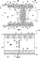
FIG. 1 is a cross-sectional schematic of a portion of structurally integrated thermal management system in accordance with disclosed embodiments. -
FIG. 2 is a side-view, cross-sectional schematic along line 2-2 ofFIG. 1 . -
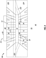
FIG. 3 is a top-view, cross-sectional schematic along line 3-3 ofFIG. 1 . - While the disclosure is susceptible to various modifications and alternative forms, specific embodiments have been shown by way of example in the drawings and will be described in detail herein. However, it should be understood that the disclosure is not intended to be limited to the particular forms disclosed. Rather, the intention is to cover all modifications and alternatives falling within the scope of the invention as defined by the appended claims.
- The embodiments described herein provide an improved, lightweight system to manage heat loads caused by EAS and other electrical systems in composite aircraft components. The disclosed system recovers, and potentially improves upon, the heat conduction of metal structures while retaining the weight savings of composite structures. This is accomplished by the intimate integration of heat conduction paths into composite structures. More specifically, there is disclosed a composite stiffener assembly for an aircraft component (e.g., a spar assembly for a wing) that includes an inner, thermally-conductive material that can transfer heat from a heat load (e.g., an EAS) to a heat sink which includes ambient atmosphere, a wing tank, some other internal or external tank, a phase change material, some other location, or combinations of the foregoing. The thermally-conductive material has a higher heat conductivity than the surrounding composite material to create a thermal path to, at least, the aircraft skin. The thermal path enables heat to transfer from the heat load, through the thermally-conductive material to the wing skin, and from the exterior surface of the skin to the ambient atmosphere (which can be quite cold at altitude).
-
FIG. 1 is a front-view, cross-sectional schematic of a portion of structurally integratedthermal management system 10 in accordance with disclosed embodiments. As shown,system 10 includes astructural member 22, aheat transfer member 12, and at least one first fastener 30. Thestructural member 22 includes and/or is formed from a composite material. Theheat transfer member 12 is in thermal contact with thestructural member 22 and aheat sink 23. The first fastener(s) 30 includes and/or is formed from a thermally-conductive material. The first fastener(s) 30 is in thermal contact with theheat transfer member 12 and couples aheat load source 24 to the compositestructural member 22. The first fastener(s) 30 conducts heat from theheat load source 24 into theheat transfer member 12, and theheat transfer member 12 conducts heat from the first fastener(s) 30 to aheat sink 23. Thesystem 10 and its components are described in more detail herein. - The
heat transfer member 12 is formed from the thermally-conductive material 14. The thermally-conductive material 14 is preferably a solid, although it need not be, that is not reactive with the composite material 16 (e.g., absent a galvanic barrier, aluminum and carbon fiber react with each other and are, thus, a less desirable combination). Theheat transfer member 12 can be formed from a carbon foam, or other material. For example,heat transfer member 12 is formed of thermally-conductive materials such as metals, non-metals, pyrolytic graphite strips or straps, copper strips or straps, silver strips or straps, graphene, carbon nano tube straps or strips, or the like. Other materials for theheat transfer member 12 are a metallic foam, a microlattice, or the like. Embodiments employing a microlattice may also utilize a cooling fluid flowing through or around the microlattice to improve heat transfer performance. - The carbon foam used in or as
heat transfer member 12 can be "graphitic" or "non-graphitic" and have higher thermal and electrical conductivity with a lower density than, for example, a metal. In one example whereheat transfer member 12 is or includes a graphitic foam, the effective thermal conductivity of the graphitic foam is more than 150 W/(m-K), which is higher than the value of 2-26 W/(m-K) for aluminum. Likewise, the density of the graphitic foam in this example is 0.2 - 0.6 g/cm3, which is approximately one-fifth the density of aluminum. Thus, where weight is a consideration, as it is in aircraft, the low density and high thermal conductivity of carbon foam is advantageous for use as or inheat transfer member 12. - As described above, the
system 10 includes one or morestructural members 22 that are formed from a composite material, such as CFRP. Awing spar 20 includes at least astructural member 22a, a secondstructural member 22b, and a thermally-conductive material 14. Eachstructural member web portion 222, acap 224, and a base 226 (see, e.g.,FIG. 2 ). Theweb portion 222 of the firststructural member 22a is positioned adjacent to, and spaced apart from, theweb portion 222 of the secondstructural member 22b to define acentral cavity 38 between the firststructural member 22a and the secondstructural member 22b. The thermally-conductive material 14 (e.g., the heat transfer member 12) is positioned in at least a portion of thecentral cavity 38. The thermally-conductive material 14 extends to cover at least a portion of thebase 226 and thecap 224 of the firststructural member 22a and to cover at least a portion of thebase 226 and thecap 224 of the secondstructural member 22b. - A
composite wing 40 for an aircraft includes a firstcomposite wing skin 18a, thewing spar 20, a secondcomposite wing skin 18b, an electric actuation system (EAS) 25, and one or more thermally-conductivesecond fasteners 32. Thefirst wing skin 18a is in thermal contact on aninterior side 42 with theheat transfer member 12 and is exposed toambient atmosphere 46 on anexterior side 44. Thewing spar 20 has theinterior cavity 38 that contains a portion of theheat transfer member 12. Thesecond wing skin 18b is in thermal contact on aninterior side 42 with theheat transfer member 12 and is exposed toambient atmosphere 46 on anexterior side 44. TheEAS 25 is coupled to thewing spar 20 by a thermally-conductive mount 28 and at least one thermally-conductivefirst fastener 30 that extends into theinterior cavity 38 of thespar 20. TheEAS 25 is in thermal contact with theheat transfer member 12. The one or more thermally-conductivesecond fasteners 32 couple thefirst wing skin 18a and thesecond wing skin 18b to thecomposite wing spar 20 and thermally contact theheat transfer member 12. A portion of the one or more thermally-conductivesecond fasteners 32 extend through to theexterior side 44 of thefirst wing skin 18a or thesecond wing skin 18b. - For embodiments where
system 10 is incorporated into awing spar 20, as shown inFIG. 1 ,heat transfer member 12 extends throughout thewing spar 20 and is in thermal contact with theinterior side 42 ofwing skin 18. As also shown, the one or morestructural members 22 are included inwing spar 20. In the exemplary embodiment shown in the figures, eachstructural member 22 has a cross-sectional shape with linear sections connected by partially arcuate corners (i.e., a "C-channel"), or the like. Alternatively, instead of twostructural members 22, a single beam with a cross-sectional shape having generally rectangular, parallel base and cap portions separated by a generally perpendicular rectangular support (i.e., an "I beam") with a hollow interior, or the like shapedwing spar 20 may be used. Other structural members and shapes are also possible. - As disclosed herein, the
system 10 is configured to manage the heat load generated by theheat load source 24, such as theEAS 25, or the like, mounted to an aircraft structural member (e.g., structural member(s) 22 forming the wing spar 20). As shown inFIG. 1 , for embodiments where theheat load source 24 is anEAS 25, thesystem 10 also includes an electrically operatedactuator 26 and amount 28 that supports theactuator 26 in the desired position on thewing spar 20, or other structural member.Mount 28 is suitably shaped and formed of a suitable, thermally-conductive material to facilitate the transfer of heat away from theactuator 26. For example, if an outer surface of theEAS 25 is generally cylindrical, mount 28 is reciprocally curved so that theEAS 25 and themount 28 make sufficient contact to efficiently transfer heat away from theEAS 25. Likewise, mount 28 is formed from thermally-conductive materials including: stainless steel, aluminum, metals, non-metals, pyrolytic graphite blocks, carbon foams, pyrolytic graphite strips or straps, copper blocks, strips, or straps, temperature sensitive hydro gels, phase change materials, thermally-conductive epoxy, thermally-conductive polymers, thermally-conductive pastes, or other thermally-conductive material. The particular material formount 28 is selected based on, among other things, the desired strength, durability, and thermal conductivity for themount 28. -
System 10 also includes one or morefirst fasteners 30. Thefasteners 30 are configured to further enhance the thermal path from the heat load 24 (e.g., an EAS 25) to theheat transfer member 12. More specifically, as shown, thefirst fasteners 30 extend through at least two composite components (e.g., through twostructural members 22, or through astructural member 22 and the wing skin 18) and through theheat transfer member 12 between the composite components.First fasteners 30 are a metal, or other thermally-conductive material, and may vary in number and location. Accordingly, the heat fromheat source 24, e.g., anEAS 25 or the like, is transferred along thefirst fasteners 30 into theheat transfer member 12 instead of through the relatively low thermally-conductive composite components (e.g.,structural member 22 and wing skin 18). Thefirst fasteners 30 also stiffen a vertical section of the structural member(s) 22 to prevent deformation of the vertical section of the structural member(s) 22. - The
system 10 can further include at least onesecond fastener 32 formed from a thermally-conductive material.Second fasteners 32 couple thewing skin 18 to theheat transfer member 12 and the structural member(s) 22 (e.g., that form wing spar 20).Second fasteners 32 are also a metal or other thermally-conductive material and also vary in number and location. Thesecond fasteners 32 not only bear a mechanical load, but also transfer heat from theheat transfer member 12 to theheat sink 23, such as the ambient atmosphere 46 (e.g., outside wing skin 18), awing tank 48, and/or othersuitable heat sink 23. Thesecond fasteners 32 also provide a heat path to the carbon fibers of thecomposite skin 18. The carbon fibers generally have a thermal conductivity of approximately 21-180 W/(m-K) and heat will be conducted along the fibers and spread out to large parts of theskin 18. In this manner, the heat is distributed to an area much larger (e.g., hundreds or thousands times larger) than the area ofsecond fastener 32 heads, which facilitates the heat conduction to theatmosphere 46, or other surrounding environment, in that the heat has been distributed to large area. - The
first fasteners 30 andsecond fasteners 32 are sized based on the anticipated heat load and the thermal conductivity of the composite material (e.g.,wing skin 18,wing spar 20, or other structural members). In addition, thefirst fasteners 30 andsecond fasteners 32 also serve a structural, load-bearing function and are sized according to the load to be borne. Overall, to manage the heat produced by anEAS 25, or other heat generating device, coupled to the composite assembly, the thermal path is generally from theactuator 26, along anactuator mount 28, into thefirst fasteners 30, then into the heat transfer member 12 (and/or a wing tank), from theheat transfer member 12 into second fasteners 32 (and/or the composite wing skin 18), and ultimately to the heat sink 23 (e.g., theambient atmosphere 46 on the other side of the wing skin 18). InFIGS. 1-3 , thefasteners fasteners wing skin 18 fastening), or the like. - For embodiments using a
heat transfer member 12 comprising a carbon foam, which typically does not have particularly high mechanical strength, to strengthen the structural assembly (e.g., wing spar 20), stiffeningmembers 34, or the like, are positioned between thecomposite wing skin 18 and the structural member 22 (e.g., that form wing spar 20). -
FIG. 2 is a side-view, cross-sectional schematic along 2-2 ofFIG. 1 that illustrates an embodiment including stiffeningmembers 34.Channels 36 are defined between stiffeningmembers 34, and theheat transfer member 12 extends through thechannels 36. As shown, thesecond fasteners 32 are coupled through theheat transfer member 12, not through stiffeningmembers 34, in order to, among other things, facilitate the heat transfer. Embodiments of stiffeningmembers 34 include CFRP material, thermally-conductive metals, or combinations of the foregoing that add desired structural strength without adding undesired weight to the aircraft. As shown inFIG. 2 ,wing spar 20 includes aweb 222, acap 224, and abase 226. Theweb portion 222,cap 224, andbase 226 are formed by structural member(s) 22, as described above. Stiffeningmembers 34 are placed betweencap 224 andwing skin 18 on the top side, andbase 226 andwing skin 18 on the bottom side. InFIG. 2 , only a few representativefirst fasteners 30 and only a few representativesecond fasteners 32 are shown for illustrative purposes. In practice, there may be more than one row and/or column offirst fasteners 30 in theweb portion 222, and there would be more than onesecond fastener 32 in thebottom wing skin 18b. -
FIG. 3 is a top-view, cross-sectional schematic along 3-3 ofFIG. 1 with thetop wing skin 18 removed for clarity. As shown in this view,channels 36 vary in size, shape, width, and length as is desired.Heat transfer member 12 fills thevarious channels 36 as disclosed herein. Stiffeningmembers 34 are also sized and distributed as disclosed herein to add structural strength to thethermal management system 10. Again, inFIG. 3 ,first fasteners 30 are not illustrated for clarity, and a few exemplarysecond fasteners 32 are shown providing a heat path fromheat transfer member 12 to outer wing skin (not shown inFIG. 3 ). - Also provided are the following illustrative, non-exhaustive examples of the subject-matter encompassed herein, which relate to:
Athermal management system 10 for transferring heat from a heat load, the system comprising: a compositestructural member 22 that supports aheat load source 24; aheat transfer member 12 in thermal contact with the compositestructural member 22, and in thermal contact with aheat sink 23; and at least one thermally conductivefirst fastener 30, in thermal contact with theheat transfer member 12, that couples theheat load source 24 to the compositestructural member 22, and conducts heat from theheat load source 24 into theheat transfer member 12; and wherein theheat transfer member 12 conducts heat from the thermally conductivefirst fastener 30 to theheat sink 23. - The system described in the immediately preceding paragraph, wherein the
heat sink 23 comprises ambient atmosphere and the system further comprises: a thermally conductivesecond fastener 32, in thermal contact with theheat transfer member 12, and that couples acomposite wing skin 18 to the compositestructural member 22; and wherein thewing skin 18 has at least one side exposed to the ambient atmosphere, and at least a portion of the thermally conductivesecond fastener 32 extends to the at least one side exposed to the ambient atmosphere. - The system described in the immediately preceding paragraph, wherein the
composite wing skin 18 further comprises fibers in a resin and wherein the fibers are more thermally conductive than the resin. - The system described in any one of the three immediately preceding paragraphs, wherein the heat transfer member further comprises carbon foam material.
- The system described in any one of the four immediately preceding paragraphs, wherein the composite
structural member 22 has a first thermal conductivity coefficient, theheat transfer member 12 has a second thermal conductivity coefficient that is higher than the first thermal conductivity coefficient, and the at least one thermally conductivefirst fastener 30 has a third thermal conductivity coefficient that is higher than the second thermal conductivity coefficient. - The system described in any one of the five immediately preceding paragraphs, wherein the
heat load source 24 further comprises an electric actuation system (EAS). - A
composite aircraft wing 40 comprising: a firstcomposite wing skin 18a, in thermal contact on an interior side with aheat transfer member 12, and exposed to ambient atmosphere on an exterior side; acomposite wing spar 20 having an interior cavity that contains a portion of theheat transfer member 12; a secondcomposite wing skin 18b, in thermal contact on an interior side with theheat transfer member 12, and exposed to ambient atmosphere on an exterior side; an electric actuation system (EAS) coupled to thecomposite wing spar 20 by a thermally conductive mount and at least one thermally conductivefirst fastener 30 that extends into the interior cavity and is in thermal contact with theheat transfer member 12; and one or more thermally conductivesecond fasteners 32 that couple the firstcomposite wing skin 18a and the secondcomposite wing skin 18b to thecomposite wing spar 20, and thermally contact theheat transfer member 12; wherein a portion of the one or more thermally conductivesecond fasteners 32 extend through to the exterior side of the firstcomposite wing skin 18a, or the secondcomposite wing skin 18b. - The wing described in the immediately preceding paragraph, further comprising a stiffening member in contact with the
composite wing spar 20 and the interior side of the firstcomposite wing skin 18a, or the secondcomposite wing skin 18b. - The wing described in the immediately preceding paragraph, wherein the stiffening member is configured to define one or more channels.
- The wing described in the immediately preceding paragraph, wherein the one or more channels contain a portion of the
heat transfer member 12. - The wing described in any one of the four immediately preceding paragraphs, wherein the at least one thermally conductive
first fastener 30, or the at least one thermally conductivesecond fastener 32 further comprises stainless steel. - The wing described in any one of the five immediately preceding paragraphs, wherein the first
composite wing skin 18a, or the secondcomposite wing skin 18b, further comprise fibers in a resin. - The wing described in the immediately preceding paragraph, wherein the fibers comprise glass or carbon.
- A
composite wing spar 20 comprising: a first compositestructural member 22a comprising abase 226 , acap 224, and aweb portion 222; a second compositestructural member 22b comprising a base, a cap, and a web portion, wherein theweb portion 222 of the first composite structural member is positioned adjacent, and spaced apart from, the web portion of the second compositestructural member 22b to define acentral cavity 38 between the firststructural member 22a and the secondstructural member 22b; and a thermally conductive material positioned in at least a portion of thecentral cavity 38 and extending to cover at least a portion of thebase 226 and thecap 224 of the first compositestructural member 22a, and at least a portion of the base and the cap of the second compositestructural member 22b. - The
composite wing spar 20 described in the immediately preceding paragraph, wherein the thermally conductive material further comprises carbon foam. - The
composite wing spar 20 described in any one of the two immediately preceding paragraphs, further comprising a stiffening member in contact with one of thecap 224 and thebase 226 of the first compositestructural member 22a. - The
composite wing spar 20 described in any one of the three immediately preceding paragraphs, further comprising a stiffening member in contact with one of the cap and the base of the second compositestructural member 22b. - The
composite wing spar 20 described in any one of the four immediately preceding paragraphs, further comprising an electric actuation system (EAS) mounted to theweb portion 222 of the first compositestructural member 22a by a thermally conductive mount. - The
composite wing spar 20 described in the immediately preceding paragraph, further comprising a thermally conductive fastener that connects the thermally conductive mount to theweb portion 222 of the first compositestructural member 22a, and extends into the thermally conductive material positioned in at least a portion of thecentral cavity 38. - The
composite wing spar 20 described in any one of the six immediately preceding paragraphs, wherein at least one of the first compositestructural member 22a or the second compositestructural member 22b further comprise a C-channel member. - Although various examples have been shown and described, the present disclosure is not so limited and will be understood to include all such modifications and variations are would be apparent to one skilled in the art.
Claims (15)
- A thermal management system (10) for transferring heat from a heat load, the thermal management system comprising:at least one composite structural member (22) that supports a heat load source (24) that generates the heat load;a heat transfer member (12) in thermal contact with the at least one composite structural member (22) and in thermal contact with a heat sink (23); andat least one thermally conductive first fastener (30), in thermal contact with the heat transfer member (12), that couples the heat load source (24) to the at least one composite structural member (22) and conducts heat from the heat load source (24) into the heat transfer member (12),wherein:the heat transfer member (12) conducts heat from the thermally conductive first fastener (30) to the heat sink (23);the at least one composite structural member (22) is included in a composite wing spar (20);the at least one composite structural member (22) comprises a first composite structural member (22a), comprising a base (226), a cap (224), and a web portion (222) and a second composite structural member (22b), comprising a base, a cap, and a web portion;the web portion (222) of the first composite structural member (22a) is positioned adjacent and spaced apart from the web portion of the second composite structural member (22b) to define a central cavity (38) between the first composite structural member (22a) and the second composite structural member (22b); andthe heat transfer member (12) is a thermally conductive material, positioned in at least a portion of the central cavity (38) and extending to cover at least a portion of the base (226) and the cap (224) of the first composite structural member (22a) and at least a portion of the base and the cap of the second composite structural member (22b).
- The thermal management system (10) of claim 1, wherein:the heat sink (23) comprises ambient atmosphere (46);the thermal management system (10) further comprises a composite wing skin (18) and a thermally conductive second fastener (32), which is in thermal contact with the heat transfer member (12) and which couples the composite wing skin (18) to the at least one composite structural member (22);the composite wing skin (18) has at least one side, exposed to the ambient atmosphere (46); andat least a portion of the thermally conductive second fastener (32) extends to the at least one side, exposed to the ambient atmosphere (46).
- The thermal management system (10) of claim 2, wherein the composite wing skin (18) further comprises fibers in a resin and wherein the fibers are more thermally conductive than the resin.
- The thermal management system (10) of any one of claims 1 to 3, wherein the heat transfer member (12) further comprises carbon foam material.
- The thermal management system (10) of any one of claims 1 to 4, wherein:the at least one composite structural member (22) has a first thermal conductivity coefficient,the heat transfer member (12) has a second thermal conductivity coefficient that is higher than the first thermal conductivity coefficient, andthe thermally conductive first fastener (30) has a third thermal conductivity coefficient that is higher than the second thermal conductivity coefficient.
- The thermal management system (10) of any one of claims 1 to 5, wherein the heat load source (24) further comprises an electric actuation system (EAS) (25).
- The thermal management system of claim 6, when claim 6 depends on claim 3, wherein the fibers comprise glass or carbon.
- The thermal management system of any one of claims 1 to 7, further comprising at least one of:a first stiffening member (34) in contact with one of the cap (224) and the base (226) of the first composite structural member (22a); anda second stiffening member in contact with one of the cap and the base of the second composite structural member (22b).
- The thermal management system of any one of claims 1 to 8, further comprising an electric actuation system (EAS) (25) mounted to the web portion (222) of the first composite structural member (22a) by a thermally conductive mount (28).
- The thermal management system of claim 9, further comprising a thermally conductive second fastener (32) that connects the thermally conductive mount (28) to the web portion (222) of the first composite structural member (22a) and extends into the thermally conductive material positioned in at least a portion of the central cavity (38).
- A composite aircraft wing (40), comprising the thermal management system (10) of claim 9 or 10.
- The composite aircraft wing of claim 11, wherein:the at least one composite structural member (22) is included in the composite wing spar (20) having an interior cavity contains a portion of the heat transfer member (12);the heat load source (24) is the electric actuation system (EAS) (25), coupled to the composite wing spar (20) by the thermally conductive mount (28) and the thermally conductive first fastener (30);the thermally conductive first fastener (30) extends into the interior cavity and is in thermal contact with the heat transfer member (12);the composite wing skin (18) comprises:a first composite wing skin (18a) in thermal contact on an interior side (42) of the first composite wing skin (18a) with the heat transfer member (12) and exposed to the ambient atmosphere (46) on an exterior side first composite wing skin (18a); anda second composite wing skin (18b) in thermal contact on an interior side of the second composite wing skin (18b) with the heat transfer member (12) and exposed to the ambient atmosphere (46) on an exterior side of the second composite wing skin (18b); andthe composite aircraft wing further comprises a thermally conductive second fastener (32) that couples the first composite wing skin (18a) and the second composite wing skin (18b) to the composite wing spar (20) and that thermally contacts the heat transfer member (12); anda portion of the thermally conductive second fastener (32) extends through to the exterior side of the first composite wing skin (18a) or the second composite wing skin (18b).
- The composite aircraft wing (40) of claim 12, further comprising at least one stiffening member (34) in contact with the composite wing spar (20) and the interior side (42) of the first composite wing skin (18a) or the second composite wing skin (18b).
- The composite aircraft wing (40) of claim 13, wherein:the at least one stiffening member is configured to define at least one channel (36); andpreferably, the at least one channel (36) contains a portion of the heat transfer member (12).
- The composite aircraft wing (40) of any one of claims 11 to 14, further comprising an electrically operated actuator (26),
wherein:the thermally conductive mount (28) supports the electrically operated actuator (26) in a desired position on the composite wing spar (20),the thermally conductive mount (28) is configured to transfer heat away from the electrically operated actuator (26), andpreferably, the thermally conductive first fastener (30) further comprises stainless steel.
Applications Claiming Priority (2)
| Application Number | Priority Date | Filing Date | Title |
|---|---|---|---|
| US15/607,962 US10723437B2 (en) | 2017-05-30 | 2017-05-30 | System for structurally integrated thermal management for thin wing aircraft control surface actuators |
| EP18165160.5A EP3409578B1 (en) | 2017-05-30 | 2018-03-29 | A thermal management system, a composite wing, and a composite wing spar |
Related Parent Applications (2)
| Application Number | Title | Priority Date | Filing Date |
|---|---|---|---|
| EP18165160.5A Division EP3409578B1 (en) | 2017-05-30 | 2018-03-29 | A thermal management system, a composite wing, and a composite wing spar |
| EP18165160.5A Division-Into EP3409578B1 (en) | 2017-05-30 | 2018-03-29 | A thermal management system, a composite wing, and a composite wing spar |
Publications (2)
| Publication Number | Publication Date |
|---|---|
| EP3792175A1 true EP3792175A1 (en) | 2021-03-17 |
| EP3792175B1 EP3792175B1 (en) | 2023-01-25 |
Family
ID=61868316
Family Applications (2)
| Application Number | Title | Priority Date | Filing Date |
|---|---|---|---|
| EP20197832.7A Active EP3792175B1 (en) | 2017-05-30 | 2018-03-29 | A thermal management system, a composite wing, and a composite wing spar |
| EP18165160.5A Active EP3409578B1 (en) | 2017-05-30 | 2018-03-29 | A thermal management system, a composite wing, and a composite wing spar |
Family Applications After (1)
| Application Number | Title | Priority Date | Filing Date |
|---|---|---|---|
| EP18165160.5A Active EP3409578B1 (en) | 2017-05-30 | 2018-03-29 | A thermal management system, a composite wing, and a composite wing spar |
Country Status (3)
| Country | Link |
|---|---|
| US (2) | US10723437B2 (en) |
| EP (2) | EP3792175B1 (en) |
| CN (1) | CN108974324B (en) |
Families Citing this family (3)
| Publication number | Priority date | Publication date | Assignee | Title |
|---|---|---|---|---|
| CN109841692B (en) * | 2018-12-29 | 2021-01-22 | 西京学院 | Thermal management system for solar aircraft, solar aircraft and thermal management method |
| US12163547B2 (en) | 2021-03-18 | 2024-12-10 | General Electric Company | Ceramic matrix composite fastener |
| US12292000B1 (en) | 2024-02-29 | 2025-05-06 | General Electric Company | Thermal management systems having an oil tank comprising solid-solid phase change material for gas turbine engines |
Citations (7)
| Publication number | Priority date | Publication date | Assignee | Title |
|---|---|---|---|---|
| US20080277526A1 (en) * | 2005-11-18 | 2008-11-13 | Airbus Uk Limited | Aircraft Cooling Duct |
| US20090288814A1 (en) * | 2008-05-20 | 2009-11-26 | The Boeing Company. | Mixed Carbon Foam/Metallic Heat Exchanger |
| FR2937304A1 (en) * | 2008-10-16 | 2010-04-23 | Airbus France | Electrical actuator e.g. electrohydraulic actuator, for aircraft, has closed enclosure for receiving fluid, where fluid is circulated in form of vapor between evaporator and condenser and in form of liquid between condenser and evaporator |
| US20100321891A1 (en) | 2009-06-19 | 2010-12-23 | General Electric Company | Avionics Chassis |
| EP2409914A1 (en) | 2010-07-23 | 2012-01-25 | BAE SYSTEMS plc | Aircraft thermal insulation |
| US20130187004A1 (en) | 2012-01-24 | 2013-07-25 | Eads Construcciones Aeronauticas, S.A. | Fire protection device for aircraft |
| WO2016088470A1 (en) * | 2014-12-03 | 2016-06-09 | 三菱重工業株式会社 | Member |
Family Cites Families (37)
| Publication number | Priority date | Publication date | Assignee | Title |
|---|---|---|---|---|
| US4283464A (en) * | 1979-05-08 | 1981-08-11 | Norman Hascoe | Prefabricated composite metallic heat-transmitting plate unit |
| US4416349A (en) * | 1981-09-30 | 1983-11-22 | The Boeing Company | Viscoelastically damped reinforced skin structures |
| US4591400A (en) * | 1984-05-15 | 1986-05-27 | United Technologies Corporation | Method of forming a fiber reinforced composite article of a complex configuration |
| US4819720A (en) | 1984-11-09 | 1989-04-11 | Mcdonnell Douglas Corporation | Skin heat exchanger |
| US5506032A (en) | 1994-04-08 | 1996-04-09 | Martin Marietta Corporation | Structural panel having integral heat pipe network |
| US5688426A (en) * | 1995-06-07 | 1997-11-18 | The Boeing Company | Hybrid metal webbed composite beam |
| DE19542843C1 (en) * | 1995-11-17 | 1996-12-19 | Daimler Benz Aerospace Airbus | Reduction of structure heating in supersonic aircraft during flight |
| US5692558A (en) | 1996-07-22 | 1997-12-02 | Northrop Grumman Corporation | Microchannel cooling using aviation fuels for airborne electronics |
| GB9713209D0 (en) * | 1997-06-20 | 1997-08-27 | British Aerospace | Friction welding metal components |
| US6375120B1 (en) * | 1997-07-14 | 2002-04-23 | Jason M. Wolnek | Method and apparatus for building a metal/composite hybrid airplane component |
| US6463699B1 (en) * | 2001-03-23 | 2002-10-15 | Obi Corporation | Air beam construction using differential pressure chambers |
| US7197852B2 (en) * | 2002-09-20 | 2007-04-03 | The Boeing Company | Internally stiffened composite panels and methods for their manufacture |
| US6863980B2 (en) * | 2002-10-08 | 2005-03-08 | The Boeing Company | Monolithic composite firewall |
| US7325772B1 (en) | 2003-09-04 | 2008-02-05 | L-3 Communications Corporation | Aircraft heat sink and electronics enclosure |
| GB0329373D0 (en) * | 2003-12-18 | 2004-01-21 | Airbus Uk Ltd | Method of joining structural elements in an aircraft |
| US7080805B2 (en) * | 2004-05-05 | 2006-07-25 | The Boeing Company | Stiffened structures and associated methods |
| US7387277B2 (en) * | 2004-12-29 | 2008-06-17 | The Boeing Company | Aircraft wing composed of composite and metal panels |
| US8109324B2 (en) | 2005-04-14 | 2012-02-07 | Illinois Institute Of Technology | Microchannel heat exchanger with micro-encapsulated phase change material for high flux cooling |
| US8950468B2 (en) | 2007-05-11 | 2015-02-10 | The Boeing Company | Cooling system for aerospace vehicle components |
| AU2012206414A1 (en) | 2011-01-11 | 2013-08-01 | Bae Systems Plc | Turboprop-powered aircraft |
| US8640469B2 (en) | 2011-08-08 | 2014-02-04 | The Boeing Company | Aircraft supplemental liquid cooler and method |
| US9756764B2 (en) | 2011-08-29 | 2017-09-05 | Aerovironment, Inc. | Thermal management system for an aircraft avionics bay |
| US9067287B2 (en) * | 2011-08-29 | 2015-06-30 | Aerovironment, Inc. | Method of manufacturing a heat transfer system for aircraft structures |
| FR2992629B1 (en) | 2012-06-27 | 2014-09-12 | Airbus Operations Sas | DEVICE FOR MECHANICALLY CONNECTING A GOVERNMENT TO A FIXED AIRCRAFT STRUCTURAL ELEMENT AND AN AIRCRAFT SAILING MEMBER EQUIPPED WITH SAID DEVICE |
| GB2503494A (en) * | 2012-06-29 | 2014-01-01 | Bae Systems Plc | Heat exchanger comprising a fibre reinforced polymer composite |
| FR2995589B1 (en) * | 2012-09-19 | 2015-07-31 | Liebherr Aerospace Toulouse Sas | BODY PANEL FOR A TRANSPORT VEHICLE COMPRISING A THERMAL EXCHANGE DEVICE AND A TRANSPORT VEHICLE COMPRISING SUCH A BODY PANEL |
| EP2886448B1 (en) * | 2013-12-20 | 2017-03-08 | Airbus Operations GmbH | A load bearing element and a method for manufacturing a load bearing element |
| US10167550B2 (en) * | 2014-06-03 | 2019-01-01 | Aurora Flight Sciences Corporation | Multi-functional composite structures |
| US10028413B2 (en) * | 2014-07-25 | 2018-07-17 | Toyota Motor Engineering & Manufacturing North America, Inc. | Heat transfer management apparatuses having a composite lamina |
| US10514214B2 (en) * | 2014-09-10 | 2019-12-24 | Ge Aviation Systems Limited | Heat transfer assemblies |
| US10225953B2 (en) * | 2014-10-31 | 2019-03-05 | Thermal Corp. | Vehicle thermal management system |
| JP6405914B2 (en) * | 2014-11-11 | 2018-10-17 | 株式会社デンソー | HEAT EXCHANGE DEVICE AND HEAT EXCHANGE DEVICE MANUFACTURING METHOD |
| US20170197701A1 (en) * | 2015-06-02 | 2017-07-13 | Iowa State University Research Foundation, Inc. | Cooling of aerospace flight systems |
| US10161491B1 (en) * | 2015-06-24 | 2018-12-25 | The United States Of America As Represented By The Secretary Of The Air Force | Fail-safe selective self-locking actuator |
| US10299407B2 (en) * | 2015-06-29 | 2019-05-21 | Microsoft Technology Licensing, Llc | Differently oriented layered thermal conduit |
| US10029808B2 (en) * | 2016-02-29 | 2018-07-24 | The Boeing Company | Structurally integrated thermal management system for aerospace vehicles |
| US10227719B2 (en) * | 2016-03-31 | 2019-03-12 | The Boeing Company | Interwoven carbon nanotube mats |
-
2017
- 2017-05-30 US US15/607,962 patent/US10723437B2/en active Active
-
2018
- 2018-03-29 EP EP20197832.7A patent/EP3792175B1/en active Active
- 2018-03-29 EP EP18165160.5A patent/EP3409578B1/en active Active
- 2018-05-21 CN CN201810492124.4A patent/CN108974324B/en active Active
-
2020
- 2020-06-18 US US16/905,008 patent/US11273900B2/en active Active
Patent Citations (7)
| Publication number | Priority date | Publication date | Assignee | Title |
|---|---|---|---|---|
| US20080277526A1 (en) * | 2005-11-18 | 2008-11-13 | Airbus Uk Limited | Aircraft Cooling Duct |
| US20090288814A1 (en) * | 2008-05-20 | 2009-11-26 | The Boeing Company. | Mixed Carbon Foam/Metallic Heat Exchanger |
| FR2937304A1 (en) * | 2008-10-16 | 2010-04-23 | Airbus France | Electrical actuator e.g. electrohydraulic actuator, for aircraft, has closed enclosure for receiving fluid, where fluid is circulated in form of vapor between evaporator and condenser and in form of liquid between condenser and evaporator |
| US20100321891A1 (en) | 2009-06-19 | 2010-12-23 | General Electric Company | Avionics Chassis |
| EP2409914A1 (en) | 2010-07-23 | 2012-01-25 | BAE SYSTEMS plc | Aircraft thermal insulation |
| US20130187004A1 (en) | 2012-01-24 | 2013-07-25 | Eads Construcciones Aeronauticas, S.A. | Fire protection device for aircraft |
| WO2016088470A1 (en) * | 2014-12-03 | 2016-06-09 | 三菱重工業株式会社 | Member |
Also Published As
| Publication number | Publication date |
|---|---|
| CN108974324A (en) | 2018-12-11 |
| US20180346096A1 (en) | 2018-12-06 |
| US10723437B2 (en) | 2020-07-28 |
| US11273900B2 (en) | 2022-03-15 |
| EP3792175B1 (en) | 2023-01-25 |
| EP3409578B1 (en) | 2020-12-30 |
| US20200317323A1 (en) | 2020-10-08 |
| CN108974324B (en) | 2023-06-06 |
| EP3409578A1 (en) | 2018-12-05 |
Similar Documents
| Publication | Publication Date | Title |
|---|---|---|
| CA2950699C (en) | Structurally integrated thermal management system for aerospace vehicles | |
| US11273900B2 (en) | System for structurally integrated thermal management for thin wing aircraft control surface actuators | |
| KR102767229B1 (en) | Battery arrangement for structurally integrating batteries in a vehicle | |
| EP3546361B1 (en) | Cooling system for aerospace vehicle components | |
| US9923252B2 (en) | Battery pack with variable-conductance heat pipe (VCHP) cooling | |
| US20170321020A1 (en) | Composite structure comprising a resin loaded with flat graphene sheets having enhanced thermal and electrical conductivity, in particular for a satellite | |
| CN112606994A (en) | Integrated thermal control design method for wings of solar unmanned aerial vehicle | |
| JP2021515978A (en) | High conductance thermal link | |
| Steeves et al. | Optimization of thermal protection systems utilizing sandwich structures with low coefficient of thermal expansion lattice hot faces | |
| CN209938923U (en) | Special unmanned aerial vehicle structure function integration cabin section and special unmanned aerial vehicle | |
| US8908820B1 (en) | Stirling radioisotope generator and thermal management system | |
| US12565304B2 (en) | Heat exchangers for airframes | |
| CN119786459B (en) | Heat radiation structure applied to large heat consumption integrated circuit of space equipment and satellite equipment | |
| CN223396383U (en) | Distributed mounting structure of micro-channel heat dissipation system of unmanned aerial vehicle of hydrogen fuel cell | |
| US20240039077A1 (en) | Energy storage radiators | |
| CN119975756B (en) | Aircraft fuselage heat dissipation system | |
| BR102017000592A2 (en) | AEROSPACE VEHICLE, METHOD FOR COOLING OF AEROSPACE VEHICLE, AND, THERMAL MANAGEMENT SYSTEM FOR AN AEROSPACE VEHICLE | |
| BR102017000592B1 (en) | AEROSPACE VEHICLE, AND, METHOD FOR COOLING AN AEROSPACE VEHICLE | |
| WO2025184660A1 (en) | Antenna-radiator designs | |
| CN117650307A (en) | Battery heat radiation structure for unmanned aerial vehicle | |
| Chu | Composite structures for magnetosphere imager spacecraft | |
| CN110505789A (en) | Method for improving thermal conductivity of electronic module with PMI foam sandwich structure |
Legal Events
| Date | Code | Title | Description |
|---|---|---|---|
| PUAI | Public reference made under article 153(3) epc to a published international application that has entered the european phase |
Free format text: ORIGINAL CODE: 0009012 |
|
| STAA | Information on the status of an ep patent application or granted ep patent |
Free format text: STATUS: THE APPLICATION HAS BEEN PUBLISHED |
|
| AC | Divisional application: reference to earlier application |
Ref document number: 3409578 Country of ref document: EP Kind code of ref document: P |
|
| AK | Designated contracting states |
Kind code of ref document: A1 Designated state(s): AL AT BE BG CH CY CZ DE DK EE ES FI FR GB GR HR HU IE IS IT LI LT LU LV MC MK MT NL NO PL PT RO RS SE SI SK SM TR |
|
| STAA | Information on the status of an ep patent application or granted ep patent |
Free format text: STATUS: REQUEST FOR EXAMINATION WAS MADE |
|
| 17P | Request for examination filed |
Effective date: 20210803 |
|
| RBV | Designated contracting states (corrected) |
Designated state(s): AL AT BE BG CH CY CZ DE DK EE ES FI FR GB GR HR HU IE IS IT LI LT LU LV MC MK MT NL NO PL PT RO RS SE SI SK SM TR |
|
| GRAP | Despatch of communication of intention to grant a patent |
Free format text: ORIGINAL CODE: EPIDOSNIGR1 |
|
| STAA | Information on the status of an ep patent application or granted ep patent |
Free format text: STATUS: GRANT OF PATENT IS INTENDED |
|
| RIC1 | Information provided on ipc code assigned before grant |
Ipc: B32B 5/18 20060101ALN20220325BHEP Ipc: B32B 7/08 20190101ALN20220325BHEP Ipc: B32B 5/24 20060101ALN20220325BHEP Ipc: B32B 27/06 20060101ALN20220325BHEP Ipc: B64C 9/00 20060101ALN20220325BHEP Ipc: B64C 13/50 20060101ALI20220325BHEP Ipc: B64C 1/00 20060101ALI20220325BHEP Ipc: B64C 3/26 20060101ALI20220325BHEP Ipc: B64C 3/18 20060101ALI20220325BHEP Ipc: B64G 1/50 20060101ALI20220325BHEP Ipc: B64D 13/00 20060101ALI20220325BHEP Ipc: B64C 1/40 20060101AFI20220325BHEP |
|
| INTG | Intention to grant announced |
Effective date: 20220413 |
|
| GRAJ | Information related to disapproval of communication of intention to grant by the applicant or resumption of examination proceedings by the epo deleted |
Free format text: ORIGINAL CODE: EPIDOSDIGR1 |
|
| STAA | Information on the status of an ep patent application or granted ep patent |
Free format text: STATUS: REQUEST FOR EXAMINATION WAS MADE |
|
| GRAP | Despatch of communication of intention to grant a patent |
Free format text: ORIGINAL CODE: EPIDOSNIGR1 |
|
| STAA | Information on the status of an ep patent application or granted ep patent |
Free format text: STATUS: GRANT OF PATENT IS INTENDED |
|
| INTC | Intention to grant announced (deleted) | ||
| RIC1 | Information provided on ipc code assigned before grant |
Ipc: B32B 5/18 20060101ALN20220726BHEP Ipc: B32B 7/08 20190101ALN20220726BHEP Ipc: B32B 5/24 20060101ALN20220726BHEP Ipc: B32B 27/06 20060101ALN20220726BHEP Ipc: B64C 9/00 20060101ALN20220726BHEP Ipc: B64C 13/50 20060101ALI20220726BHEP Ipc: B64C 1/00 20060101ALI20220726BHEP Ipc: B64C 3/26 20060101ALI20220726BHEP Ipc: B64C 3/18 20060101ALI20220726BHEP Ipc: B64G 1/50 20060101ALI20220726BHEP Ipc: B64D 13/00 20060101ALI20220726BHEP Ipc: B64C 1/40 20060101AFI20220726BHEP |
|
| INTG | Intention to grant announced |
Effective date: 20220822 |
|
| GRAS | Grant fee paid |
Free format text: ORIGINAL CODE: EPIDOSNIGR3 |
|
| GRAA | (expected) grant |
Free format text: ORIGINAL CODE: 0009210 |
|
| STAA | Information on the status of an ep patent application or granted ep patent |
Free format text: STATUS: THE PATENT HAS BEEN GRANTED |
|
| AC | Divisional application: reference to earlier application |
Ref document number: 3409578 Country of ref document: EP Kind code of ref document: P |
|
| AK | Designated contracting states |
Kind code of ref document: B1 Designated state(s): AL AT BE BG CH CY CZ DE DK EE ES FI FR GB GR HR HU IE IS IT LI LT LU LV MC MK MT NL NO PL PT RO RS SE SI SK SM TR |
|
| REG | Reference to a national code |
Ref country code: GB Ref legal event code: FG4D |
|
| REG | Reference to a national code |
Ref country code: CH Ref legal event code: EP |
|
| REG | Reference to a national code |
Ref country code: AT Ref legal event code: REF Ref document number: 1545742 Country of ref document: AT Kind code of ref document: T Effective date: 20230215 Ref country code: IE Ref legal event code: FG4D |
|
| REG | Reference to a national code |
Ref country code: DE Ref legal event code: R096 Ref document number: 602018045871 Country of ref document: DE |
|
| RAP4 | Party data changed (patent owner data changed or rights of a patent transferred) |
Owner name: THE BOEING COMPANY |
|
| REG | Reference to a national code |
Ref country code: LT Ref legal event code: MG9D |
|
| REG | Reference to a national code |
Ref country code: NL Ref legal event code: MP Effective date: 20230125 |
|
| REG | Reference to a national code |
Ref country code: AT Ref legal event code: MK05 Ref document number: 1545742 Country of ref document: AT Kind code of ref document: T Effective date: 20230125 |
|
| P01 | Opt-out of the competence of the unified patent court (upc) registered |
Effective date: 20230516 |
|
| PG25 | Lapsed in a contracting state [announced via postgrant information from national office to epo] |
Ref country code: NL Free format text: LAPSE BECAUSE OF FAILURE TO SUBMIT A TRANSLATION OF THE DESCRIPTION OR TO PAY THE FEE WITHIN THE PRESCRIBED TIME-LIMIT Effective date: 20230125 |
|
| PG25 | Lapsed in a contracting state [announced via postgrant information from national office to epo] |
Ref country code: RS Free format text: LAPSE BECAUSE OF FAILURE TO SUBMIT A TRANSLATION OF THE DESCRIPTION OR TO PAY THE FEE WITHIN THE PRESCRIBED TIME-LIMIT Effective date: 20230125 Ref country code: PT Free format text: LAPSE BECAUSE OF FAILURE TO SUBMIT A TRANSLATION OF THE DESCRIPTION OR TO PAY THE FEE WITHIN THE PRESCRIBED TIME-LIMIT Effective date: 20230525 Ref country code: NO Free format text: LAPSE BECAUSE OF FAILURE TO SUBMIT A TRANSLATION OF THE DESCRIPTION OR TO PAY THE FEE WITHIN THE PRESCRIBED TIME-LIMIT Effective date: 20230425 Ref country code: LV Free format text: LAPSE BECAUSE OF FAILURE TO SUBMIT A TRANSLATION OF THE DESCRIPTION OR TO PAY THE FEE WITHIN THE PRESCRIBED TIME-LIMIT Effective date: 20230125 Ref country code: LT Free format text: LAPSE BECAUSE OF FAILURE TO SUBMIT A TRANSLATION OF THE DESCRIPTION OR TO PAY THE FEE WITHIN THE PRESCRIBED TIME-LIMIT Effective date: 20230125 Ref country code: HR Free format text: LAPSE BECAUSE OF FAILURE TO SUBMIT A TRANSLATION OF THE DESCRIPTION OR TO PAY THE FEE WITHIN THE PRESCRIBED TIME-LIMIT Effective date: 20230125 Ref country code: ES Free format text: LAPSE BECAUSE OF FAILURE TO SUBMIT A TRANSLATION OF THE DESCRIPTION OR TO PAY THE FEE WITHIN THE PRESCRIBED TIME-LIMIT Effective date: 20230125 Ref country code: AT Free format text: LAPSE BECAUSE OF FAILURE TO SUBMIT A TRANSLATION OF THE DESCRIPTION OR TO PAY THE FEE WITHIN THE PRESCRIBED TIME-LIMIT Effective date: 20230125 |
|
| PG25 | Lapsed in a contracting state [announced via postgrant information from national office to epo] |
Ref country code: SE Free format text: LAPSE BECAUSE OF FAILURE TO SUBMIT A TRANSLATION OF THE DESCRIPTION OR TO PAY THE FEE WITHIN THE PRESCRIBED TIME-LIMIT Effective date: 20230125 Ref country code: PL Free format text: LAPSE BECAUSE OF FAILURE TO SUBMIT A TRANSLATION OF THE DESCRIPTION OR TO PAY THE FEE WITHIN THE PRESCRIBED TIME-LIMIT Effective date: 20230125 Ref country code: IS Free format text: LAPSE BECAUSE OF FAILURE TO SUBMIT A TRANSLATION OF THE DESCRIPTION OR TO PAY THE FEE WITHIN THE PRESCRIBED TIME-LIMIT Effective date: 20230525 Ref country code: GR Free format text: LAPSE BECAUSE OF FAILURE TO SUBMIT A TRANSLATION OF THE DESCRIPTION OR TO PAY THE FEE WITHIN THE PRESCRIBED TIME-LIMIT Effective date: 20230426 Ref country code: FI Free format text: LAPSE BECAUSE OF FAILURE TO SUBMIT A TRANSLATION OF THE DESCRIPTION OR TO PAY THE FEE WITHIN THE PRESCRIBED TIME-LIMIT Effective date: 20230125 |
|
| REG | Reference to a national code |
Ref country code: DE Ref legal event code: R097 Ref document number: 602018045871 Country of ref document: DE |
|
| PG25 | Lapsed in a contracting state [announced via postgrant information from national office to epo] |
Ref country code: SM Free format text: LAPSE BECAUSE OF FAILURE TO SUBMIT A TRANSLATION OF THE DESCRIPTION OR TO PAY THE FEE WITHIN THE PRESCRIBED TIME-LIMIT Effective date: 20230125 Ref country code: RO Free format text: LAPSE BECAUSE OF FAILURE TO SUBMIT A TRANSLATION OF THE DESCRIPTION OR TO PAY THE FEE WITHIN THE PRESCRIBED TIME-LIMIT Effective date: 20230125 Ref country code: MC Free format text: LAPSE BECAUSE OF FAILURE TO SUBMIT A TRANSLATION OF THE DESCRIPTION OR TO PAY THE FEE WITHIN THE PRESCRIBED TIME-LIMIT Effective date: 20230125 Ref country code: EE Free format text: LAPSE BECAUSE OF FAILURE TO SUBMIT A TRANSLATION OF THE DESCRIPTION OR TO PAY THE FEE WITHIN THE PRESCRIBED TIME-LIMIT Effective date: 20230125 Ref country code: DK Free format text: LAPSE BECAUSE OF FAILURE TO SUBMIT A TRANSLATION OF THE DESCRIPTION OR TO PAY THE FEE WITHIN THE PRESCRIBED TIME-LIMIT Effective date: 20230125 Ref country code: CZ Free format text: LAPSE BECAUSE OF FAILURE TO SUBMIT A TRANSLATION OF THE DESCRIPTION OR TO PAY THE FEE WITHIN THE PRESCRIBED TIME-LIMIT Effective date: 20230125 |
|
| REG | Reference to a national code |
Ref country code: CH Ref legal event code: PL |
|
| PG25 | Lapsed in a contracting state [announced via postgrant information from national office to epo] |
Ref country code: SK Free format text: LAPSE BECAUSE OF FAILURE TO SUBMIT A TRANSLATION OF THE DESCRIPTION OR TO PAY THE FEE WITHIN THE PRESCRIBED TIME-LIMIT Effective date: 20230125 |
|
| REG | Reference to a national code |
Ref country code: BE Ref legal event code: MM Effective date: 20230331 |
|
| PLBE | No opposition filed within time limit |
Free format text: ORIGINAL CODE: 0009261 |
|
| STAA | Information on the status of an ep patent application or granted ep patent |
Free format text: STATUS: NO OPPOSITION FILED WITHIN TIME LIMIT |
|
| PG25 | Lapsed in a contracting state [announced via postgrant information from national office to epo] |
Ref country code: LU Free format text: LAPSE BECAUSE OF NON-PAYMENT OF DUE FEES Effective date: 20230329 |
|
| 26N | No opposition filed |
Effective date: 20231026 |
|
| REG | Reference to a national code |
Ref country code: IE Ref legal event code: MM4A |
|
| PG25 | Lapsed in a contracting state [announced via postgrant information from national office to epo] |
Ref country code: SI Free format text: LAPSE BECAUSE OF FAILURE TO SUBMIT A TRANSLATION OF THE DESCRIPTION OR TO PAY THE FEE WITHIN THE PRESCRIBED TIME-LIMIT Effective date: 20230125 Ref country code: LI Free format text: LAPSE BECAUSE OF NON-PAYMENT OF DUE FEES Effective date: 20230331 Ref country code: IE Free format text: LAPSE BECAUSE OF NON-PAYMENT OF DUE FEES Effective date: 20230329 Ref country code: CH Free format text: LAPSE BECAUSE OF NON-PAYMENT OF DUE FEES Effective date: 20230331 |
|
| PG25 | Lapsed in a contracting state [announced via postgrant information from national office to epo] |
Ref country code: BE Free format text: LAPSE BECAUSE OF NON-PAYMENT OF DUE FEES Effective date: 20230331 |
|
| PG25 | Lapsed in a contracting state [announced via postgrant information from national office to epo] |
Ref country code: IT Free format text: LAPSE BECAUSE OF FAILURE TO SUBMIT A TRANSLATION OF THE DESCRIPTION OR TO PAY THE FEE WITHIN THE PRESCRIBED TIME-LIMIT Effective date: 20230125 |
|
| PG25 | Lapsed in a contracting state [announced via postgrant information from national office to epo] |
Ref country code: BG Free format text: LAPSE BECAUSE OF FAILURE TO SUBMIT A TRANSLATION OF THE DESCRIPTION OR TO PAY THE FEE WITHIN THE PRESCRIBED TIME-LIMIT Effective date: 20230125 |
|
| PG25 | Lapsed in a contracting state [announced via postgrant information from national office to epo] |
Ref country code: BG Free format text: LAPSE BECAUSE OF FAILURE TO SUBMIT A TRANSLATION OF THE DESCRIPTION OR TO PAY THE FEE WITHIN THE PRESCRIBED TIME-LIMIT Effective date: 20230125 |
|
| PG25 | Lapsed in a contracting state [announced via postgrant information from national office to epo] |
Ref country code: CY Free format text: LAPSE BECAUSE OF FAILURE TO SUBMIT A TRANSLATION OF THE DESCRIPTION OR TO PAY THE FEE WITHIN THE PRESCRIBED TIME-LIMIT; INVALID AB INITIO Effective date: 20180329 |
|
| PG25 | Lapsed in a contracting state [announced via postgrant information from national office to epo] |
Ref country code: HU Free format text: LAPSE BECAUSE OF FAILURE TO SUBMIT A TRANSLATION OF THE DESCRIPTION OR TO PAY THE FEE WITHIN THE PRESCRIBED TIME-LIMIT; INVALID AB INITIO Effective date: 20180329 |
|
| PG25 | Lapsed in a contracting state [announced via postgrant information from national office to epo] |
Ref country code: TR Free format text: LAPSE BECAUSE OF FAILURE TO SUBMIT A TRANSLATION OF THE DESCRIPTION OR TO PAY THE FEE WITHIN THE PRESCRIBED TIME-LIMIT Effective date: 20230125 |
|
| PGFP | Annual fee paid to national office [announced via postgrant information from national office to epo] |
Ref country code: GB Payment date: 20260327 Year of fee payment: 9 |
|
| PGFP | Annual fee paid to national office [announced via postgrant information from national office to epo] |
Ref country code: DE Payment date: 20260327 Year of fee payment: 9 |
|
| PGFP | Annual fee paid to national office [announced via postgrant information from national office to epo] |
Ref country code: FR Payment date: 20260325 Year of fee payment: 9 |