EP3792164A1 - Active front splitter for automobile - Google Patents
Active front splitter for automobile Download PDFInfo
- Publication number
- EP3792164A1 EP3792164A1 EP19207884.8A EP19207884A EP3792164A1 EP 3792164 A1 EP3792164 A1 EP 3792164A1 EP 19207884 A EP19207884 A EP 19207884A EP 3792164 A1 EP3792164 A1 EP 3792164A1
- Authority
- EP
- European Patent Office
- Prior art keywords
- splitter
- active front
- connecting rod
- front splitter
- support
- Prior art date
- Legal status (The legal status is an assumption and is not a legal conclusion. Google has not performed a legal analysis and makes no representation as to the accuracy of the status listed.)
- Granted
Links
Images
Classifications
-
- B—PERFORMING OPERATIONS; TRANSPORTING
- B62—LAND VEHICLES FOR TRAVELLING OTHERWISE THAN ON RAILS
- B62D—MOTOR VEHICLES; TRAILERS
- B62D35/00—Vehicle bodies characterised by streamlining
- B62D35/005—Front spoilers
-
- B—PERFORMING OPERATIONS; TRANSPORTING
- B62—LAND VEHICLES FOR TRAVELLING OTHERWISE THAN ON RAILS
- B62D—MOTOR VEHICLES; TRAILERS
- B62D37/00—Stabilising vehicle bodies without controlling suspension arrangements
- B62D37/02—Stabilising vehicle bodies without controlling suspension arrangements by aerodynamic means
-
- B—PERFORMING OPERATIONS; TRANSPORTING
- B62—LAND VEHICLES FOR TRAVELLING OTHERWISE THAN ON RAILS
- B62D—MOTOR VEHICLES; TRAILERS
- B62D35/00—Vehicle bodies characterised by streamlining
- B62D35/02—Streamlining the undersurfaces
-
- Y—GENERAL TAGGING OF NEW TECHNOLOGICAL DEVELOPMENTS; GENERAL TAGGING OF CROSS-SECTIONAL TECHNOLOGIES SPANNING OVER SEVERAL SECTIONS OF THE IPC; TECHNICAL SUBJECTS COVERED BY FORMER USPC CROSS-REFERENCE ART COLLECTIONS [XRACs] AND DIGESTS
- Y02—TECHNOLOGIES OR APPLICATIONS FOR MITIGATION OR ADAPTATION AGAINST CLIMATE CHANGE
- Y02T—CLIMATE CHANGE MITIGATION TECHNOLOGIES RELATED TO TRANSPORTATION
- Y02T10/00—Road transport of goods or passengers
- Y02T10/80—Technologies aiming to reduce greenhouse gasses emissions common to all road transportation technologies
- Y02T10/82—Elements for improving aerodynamics
Definitions
- the invention relates to the field of automotive exterior parts, and more particularly, an active front splitter.
- a fixed-type splitter used in automobile has a certain capacity of improving aerodynamic performance.
- An automobile splitter reduces the amount of air entering the automobile by preventing air from entering its chassis.
- the pressure on the chassis is reduced, increasing the downforce of the automobile. Therefore, the wind drag can be effectively reduced.
- the height of the splitter is limited, which causes poor results of the reduction of wind drag.
- the invention provides an active front splitter for automobile.
- the active front splitter for automobile provided by the invention is rotatably connected to a splitter support by spindle supports fixed at its two ends.
- a driving mechanism of the active front splitter is mounted to each end of the splitter support.
- An electric motor is mounted in the middle of the splitter support.
- the driving mechanisms are driven by the electric motor and are fixedly connected with the active front splitter so that the active front splitter is driven by the driving mechanism to rotate around a spindle fixed to the splitter support between a forwardly extended position and a retreated position.
- the driving mechanism comprises a primary driving rod which is connected with the electric motor, a secondary driving rod fixed to the primary driving rod, a first connecting rod movably connected with the secondary driving rod and pivotally connected with the splitter support, and a second connecting rod pivotally connected with the first connecting rod and fixed to the active front splitter.
- the spindle support defines the axis and radius of the rotation of the active front splitter, which is driven by the multiple rods transmission mechanism to move.
- one end of the first connecting rod is pivotally connected with the splitter support and the other end is hinged with the second connecting rod.
- the secondary driving rod is provided with a slider
- the first connecting rod is provided with a sliding slot in which the slider slides. With the rotation of the secondary driving rod, the slider slides in the sliding slot, which is for example an elongated slot along the first connecting rod, so as to rotate the first connecting rod relative to the splitter support.
- the active front splitter comprises an inner panel and an outer panel which is bonded to an external surface of the inner panel. In other embodiments, the active front splitter may only comprise a unique panel.
- an anti-wearing plate is screwed at each of the two ends of the splitter support.
- the electric motor is provided with a motor cover.
- the driving mechanism is provided with a sand prevention cover.
- the angle between the first connecting rod and the second connecting rod is 180° and the angle between the secondary driving rod and the first connecting rod is 90°.
- This embodiment is particularly interesting since the structure constituted here is self-locked when the active front splitter is subject to exterior force, such as high-speed wind force or impact of debris.
- the angle between the first connecting rod and the second connecting rod is smaller than 90° and the secondary driving rod and the first connecting rod are substantially parallel to each other.
- the secondary driving rod, the first and second connecting rods are folded together and occupies a smaller space.
- the active front splitter is retreated rearward to a maximum extent.
- the invention provides an active front splitter for automobile to remedy the drawback of a fixed-type splitter that it is unable to effectively reduce air drag.
- the active front splitter is able to rotate between two operating positions: forwardly extended position and retreated position.
- the ground clearance of the automobile is reduced, thus reducing the amount of air entering the automobile chassis, increasing the downforce, and thus reducing wind drag.
- the active front splitter is in the retreated position, the ground clearance of the automobile is increased, in order to meet the trafficability requirements. Therefore, the invention is able to ensure the trafficability of assembled automobile while reducing the wind drag and thus achieving expected aerodynamic performance.
- an active front splitter for automobile comprises a splitter support 1, a spindle support 2, a driving mechanism 3, an electric motor 4, an inner panel 5 of the front splitter, and an outer panel 6 of the front splitter.
- the splitter support 1 is provided with the driving mechanism 3 at each of its two ends, and the electric motor 4 at its middle.
- One end of the spindle supports 2 is hinged to the splitter support 1, and the other end of them is fixed to the inner panel 5 of the front splitter.
- the inner panel 5 and the outer panel 6 of the front splitter are bonded together by an adhesive tape.
- the driving mechanism 3 comprises a primary driving rod 30, a secondary driving rod 31, a first connecting rod 32 and a second connecting rod 33.
- the primary driving rod 30 is mounted inside the splitter support 1, with one end connected to the electric motor 4, and the other end fixed with the secondary driving rod 31.
- One end of the first connecting rod 32 is pivotally connected with the splitter support 1.
- the other end of the first connecting rod 32 is pivotally connected with, for example hinged with, the second connecting rod 33 via a pivot 11, so that the second connecting rod 33 can rotate around the pivot 11.
- the other end of the second connecting rod 33 is fixed to the inner panel 5 of the front splitter.
- the first connecting rod 32 comprises a sliding slot 10 in the middle.
- the sliding slot 10 is an elongated slot extending in the longitudinal direction of the first connecting rod 32.
- the secondary driving rod 31 comprises a slider 13. The slider 13 is able to slide inside the sliding slot 10.
- the active front splitter works as follows: the electric motor 4 drives the primary driving rod 30 to rotate, which in turn drives the secondary driving rod 31 to rotate.
- the first connecting rod 32 is driven to rotate around its pivot relative to the splitter support 1.
- the second connecting rod 33 is driven to move, thus driving the active front splitter to rotate around its spindle on the splitter support 1.
- the active front splitter is moved to the forwardly extended position. At this moment, the ground clearance of the automobile is reduced, thus reducing the amount of air entering the automobile's chassis, increasing the downforce thus reducing the wind drag.
- the active front splitter When encountering an obstacle or a rugged road surface, the active front splitter is moved to the retreated position. At this moment, the ground clearance of the automobile is increased so that the automobile can successfully pass.
- the active front splitter is in the forwardly extended position.
- the first and second connecting rods are aligned and the secondary driving rod 31 is perpendicular to this line, no rotation torque due to exterior force applied to the active front splitter 2 can be transmitted to the pivots.
- the driving mechanism 3 is in a self-locked state. Thanks to the locked state, the driving mechanism 3 can sustain relatively high wind pressure and impact forces of debris, thus improving the safety and stability of the mechanism.
- the active front splitter of the present embodiment comprises an inner panel 5 and an outer panel 6 bonded together by an adhesive tape.
- the active front splitter according to the invention does not have an outer panel.
- the splitter support 1 is further provided with an anti-wearing plate 12.
- the anti-wearing plate is mounted to the splitter support 1 by a screw and has a form that is easy to produce. It can enhance the endurance of the active front splitter and facilitate the production and assembly at the same time.
- the electric motor 4 is provided with a motor cover 7, and each driving mechanism 3 is provided with a sand prevention cover 8.
- the covers are used for protecting, respectively, the electric motor and the driving mechanisms against impacts of debris. Therefore, the structure of the active front splitter is effectively protected during use.
- Both the active front splitter 1 and the electric motor 4 are provided with threaded holes 13, and the motor cover 7 and the sand prevention covers 8 are respectively mounted to the electric motor 4 and the driving mechanisms by screws.
Landscapes
- Engineering & Computer Science (AREA)
- Chemical & Material Sciences (AREA)
- Combustion & Propulsion (AREA)
- Transportation (AREA)
- Mechanical Engineering (AREA)
- Physics & Mathematics (AREA)
- Fluid Mechanics (AREA)
- Body Structure For Vehicles (AREA)
- Non-Portable Lighting Devices Or Systems Thereof (AREA)
Abstract
Description
- The invention relates to the field of automotive exterior parts, and more particularly, an active front splitter.
- Currently, environmental pollution has become more and more serious. National policies impose stricter environmental requirements, requiring automobiles to reduce the emission of CO2. As consumers' costs of using automobiles increase, they also urgently hope to reduce energy consumption of automobiles. To achieve the above-described objectives, current solutions include: reducing the weight of an assembled automobile; reducing rolling resistance; developing electric automobiles. However, reducing the weight of an assembled automobile will affect its stability; reducing rolling resistance will increase the costs of tires; and electric automobiles have a limited range and rely on immature technologies.
- A fixed-type splitter used in automobile has a certain capacity of improving aerodynamic performance. An automobile splitter reduces the amount of air entering the automobile by preventing air from entering its chassis. Thus, the pressure on the chassis is reduced, increasing the downforce of the automobile. Therefore, the wind drag can be effectively reduced. However, because of the trafficability requirements, the height of the splitter is limited, which causes poor results of the reduction of wind drag.
- To solve the problem of limited splitter height in the prior art that causes poor results of wind drag reduction, the invention provides an active front splitter for automobile.
- The active front splitter for automobile provided by the invention is rotatably connected to a splitter support by spindle supports fixed at its two ends. A driving mechanism of the active front splitter is mounted to each end of the splitter support. An electric motor is mounted in the middle of the splitter support. The driving mechanisms are driven by the electric motor and are fixedly connected with the active front splitter so that the active front splitter is driven by the driving mechanism to rotate around a spindle fixed to the splitter support between a forwardly extended position and a retreated position.
- In an embodiment, the driving mechanism comprises a primary driving rod which is connected with the electric motor, a secondary driving rod fixed to the primary driving rod, a first connecting rod movably connected with the secondary driving rod and pivotally connected with the splitter support, and a second connecting rod pivotally connected with the first connecting rod and fixed to the active front splitter.
- Thus, the spindle support defines the axis and radius of the rotation of the active front splitter, which is driven by the multiple rods transmission mechanism to move.
- In an embodiment, one end of the first connecting rod is pivotally connected with the splitter support and the other end is hinged with the second connecting rod. In an embodiment, the secondary driving rod is provided with a slider, the first connecting rod is provided with a sliding slot in which the slider slides. With the rotation of the secondary driving rod, the slider slides in the sliding slot, which is for example an elongated slot along the first connecting rod, so as to rotate the first connecting rod relative to the splitter support.
- In an embodiment, the active front splitter comprises an inner panel and an outer panel which is bonded to an external surface of the inner panel. In other embodiments, the active front splitter may only comprise a unique panel.
- In an embodiment, an anti-wearing plate is screwed at each of the two ends of the splitter support.
- In an embodiment, the electric motor is provided with a motor cover.
- In an embodiment, the driving mechanism is provided with a sand prevention cover.
- In an embodiment, when the active front splitter is in the forwardly extended position, the angle between the first connecting rod and the second connecting rod is 180° and the angle between the secondary driving rod and the first connecting rod is 90°. This embodiment is particularly interesting since the structure constituted here is self-locked when the active front splitter is subject to exterior force, such as high-speed wind force or impact of debris.
- In an embodiment, when the active front splitter is in a retreated position, the angle between the first connecting rod and the second connecting rod is smaller than 90° and the secondary driving rod and the first connecting rod are substantially parallel to each other. In other words, the secondary driving rod, the first and second connecting rods are folded together and occupies a smaller space. The active front splitter is retreated rearward to a maximum extent.
- The invention provides an active front splitter for automobile to remedy the drawback of a fixed-type splitter that it is unable to effectively reduce air drag. By means of the driving mechanisms that are driven by the electric motor, the active front splitter is able to rotate between two operating positions: forwardly extended position and retreated position. When the active front splitter is in the forwardly extended position, the ground clearance of the automobile is reduced, thus reducing the amount of air entering the automobile chassis, increasing the downforce, and thus reducing wind drag. When the active front splitter is in the retreated position, the ground clearance of the automobile is increased, in order to meet the trafficability requirements. Therefore, the invention is able to ensure the trafficability of assembled automobile while reducing the wind drag and thus achieving expected aerodynamic performance.
-
-
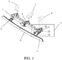
Figure 1 is a schematic diagram of an active front splitter according to the invention. -
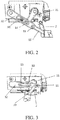
Figure 2 is a schematic view of an active front splitter according to the invention in a forwardly extended position. -
Figure 3 is a schematic view of an active front splitter according to the invention in a retreated position. -
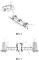
Figure 4 is an assembled view of an active front splitter according to the invention and an anti-wearing plate. -
Figure 5 is an assembled view of a sand prevention cover according to the invention and a motor cover. - The following provides preferred embodiments of the present invention with reference to the accompanying drawings and provides detailed descriptions.
- As shown in
Figure 1 , an active front splitter for automobile comprises asplitter support 1, aspindle support 2, adriving mechanism 3, an electric motor 4, aninner panel 5 of the front splitter, and anouter panel 6 of the front splitter. Thesplitter support 1 is provided with thedriving mechanism 3 at each of its two ends, and the electric motor 4 at its middle. One end of the spindle supports 2 is hinged to thesplitter support 1, and the other end of them is fixed to theinner panel 5 of the front splitter. Theinner panel 5 and theouter panel 6 of the front splitter are bonded together by an adhesive tape. - The
driving mechanism 3 comprises aprimary driving rod 30, asecondary driving rod 31, a first connectingrod 32 and a second connectingrod 33. Theprimary driving rod 30 is mounted inside thesplitter support 1, with one end connected to the electric motor 4, and the other end fixed with thesecondary driving rod 31. One end of the first connectingrod 32 is pivotally connected with thesplitter support 1. The other end of the first connectingrod 32 is pivotally connected with, for example hinged with, the second connectingrod 33 via apivot 11, so that the second connectingrod 33 can rotate around thepivot 11. The other end of the second connectingrod 33 is fixed to theinner panel 5 of the front splitter. The first connectingrod 32 comprises asliding slot 10 in the middle. In the illustrated embodiment, thesliding slot 10 is an elongated slot extending in the longitudinal direction of the first connectingrod 32. Thesecondary driving rod 31 comprises aslider 13. Theslider 13 is able to slide inside thesliding slot 10. - The active front splitter according to the invention works as follows: the electric motor 4 drives the
primary driving rod 30 to rotate, which in turn drives thesecondary driving rod 31 to rotate. By means of the cooperation between theslider 13 carried by thesecondary driving rod 31 and thesliding slot 10 in the first connectingrod 32, the first connectingrod 32 is driven to rotate around its pivot relative to thesplitter support 1. The second connectingrod 33 is driven to move, thus driving the active front splitter to rotate around its spindle on thesplitter support 1. When the automobile runs normally, the active front splitter is moved to the forwardly extended position. At this moment, the ground clearance of the automobile is reduced, thus reducing the amount of air entering the automobile's chassis, increasing the downforce thus reducing the wind drag. When encountering an obstacle or a rugged road surface, the active front splitter is moved to the retreated position. At this moment, the ground clearance of the automobile is increased so that the automobile can successfully pass. - As shown in
Figure 2 , when the angle between the first connectingrod 32 and the second connectingrod 33 is 180° and the angle between thesecondary driving rod 31 and the first connectingrod 32 is 90°, the active front splitter is in the forwardly extended position. At this moment, the first and second connecting rods are aligned and thesecondary driving rod 31 is perpendicular to this line, no rotation torque due to exterior force applied to the activefront splitter 2 can be transmitted to the pivots. Thus, thedriving mechanism 3 is in a self-locked state. Thanks to the locked state, thedriving mechanism 3 can sustain relatively high wind pressure and impact forces of debris, thus improving the safety and stability of the mechanism. - As shown in
Figure 3 , when the angle between the first connectingrod 32 and the second connectingrod 33 is smaller than 90° and thesecondary driving rod 31 and the first connectingrod 32 are substantially parallel to each other, the active front splitter is in the retreated position. At this moment, the active front splitter has completely retreated. The trafficabiity requirements of the automobile are satisfied. - Considering the aesthetic requirements, the active front splitter of the present embodiment comprises an
inner panel 5 and anouter panel 6 bonded together by an adhesive tape. Of course, it is also possible that the active front splitter according to the invention does not have an outer panel. - In the present embodiment, the
splitter support 1 is further provided with ananti-wearing plate 12. As shown inFigure 4 , the anti-wearing plate is mounted to thesplitter support 1 by a screw and has a form that is easy to produce. It can enhance the endurance of the active front splitter and facilitate the production and assembly at the same time. - In the present embodiment, as shown in
Figure 5 , the electric motor 4 is provided with amotor cover 7, and eachdriving mechanism 3 is provided with asand prevention cover 8. The covers are used for protecting, respectively, the electric motor and the driving mechanisms against impacts of debris. Therefore, the structure of the active front splitter is effectively protected during use. Both the activefront splitter 1 and the electric motor 4 are provided with threadedholes 13, and themotor cover 7 and the sand prevention covers 8 are respectively mounted to the electric motor 4 and the driving mechanisms by screws. - The foregoing descriptions are merely preferred embodiments of the present invention and are not intended to limit the scope of the present invention. Various changes may be further made to the foregoing embodiments of the present invention. That is, a simple, equivalent change and modification made according to the claims of this application and the content of the specification of the present invention shall fall within the protection scope of the present invention. What is not described in detail in the present invention all belongs to common technologies.
Claims (10)
- An active front splitter for automobile, rotatably connected to a splitter support (1) by spindle supports (2) fixed at its two ends, a driving mechanism (3) of the active front splitter being mounted to each end of the splitter support (1), an electric motor (4) being mounted in the middle of the splitter support (1), the driving mechanisms (3) being driven by the electric motor (4) and fixedly connected with the active front splitter, so that the active front splitter is driven by the driving mechanism (3) to rotate around a spindle fixed to the splitter support (1) between a forwardly extended position and a retreated position.
- The active front splitter according to claim 1, wherein the driving mechanism (3) comprises:- a primary driving rod (30), which is connected with the electric motor (4);- a secondary driving rod (31) fixed to the primary driving rod (30),- a first connecting rod (32) moveably connected with the secondary driving rod (31) and pivotally connected with the splitter support (1), and- a second connecting rod (33) pivotally connected with the first connecting rod (32) and fixed to the active front splitter.
- The active front splitter according to claim 2, wherein one end of the first connecting rod (32) is pivotally connected with the splitter support (1) and the other end is hinged with the second connecting rod (33).
- The active front splitter according to claim 2 or 3, wherein the secondary driving rod (31) is provided with a slider (13), the first connecting rod is provided with a sliding slot (10) in which the slider (13) slides so as to rotate the first connecting rod (32) relative to the splitter support (1).
- The active front splitter according to anyone of the preceding claims, wherein the active front splitter comprises an inner panel (5) and an outer panel (6) which is bonded to an external surface of the inner panel (5).
- The active front splitter according to anyone of the preceding claims, wherein an anti-wearing plate (12) is screwed at each of the two ends of the splitter support (1).
- The active front splitter according to anyone of the preceding claims, wherein the electric motor (4) is provided with a motor cover (7).
- The active front splitter according to anyone of the preceding claims, wherein the driving mechanism (3) is provided with a sand prevention cover (8).
- The active front splitter according to anyone of claims 2 to 8, wherein, when the active front splitter is in the forwardly extended position, the angle between the first connecting rod (32) and the second connecting rod (33) is 180° and the angle between the secondary driving rod (31) and the first connecting rod (32) is 90°.
- The active front splitter according to anyone of claims 2 to 9, wherein, when the active front splitter is in the retreated position, the angle between the first connecting rod (32) and the second connecting rod (33) is smaller than 90° and the secondary driving rod (31) and the first connecting rod (32) are substantially parallel to each other.
Applications Claiming Priority (2)
| Application Number | Priority Date | Filing Date | Title |
|---|---|---|---|
| CN201910854176.6A CN110466626B (en) | 2019-09-10 | 2019-09-10 | Active front lip of automobile |
| CN201921501221.1U CN210478846U (en) | 2019-09-10 | 2019-09-10 | A car active front lip |
Publications (2)
| Publication Number | Publication Date |
|---|---|
| EP3792164A1 true EP3792164A1 (en) | 2021-03-17 |
| EP3792164B1 EP3792164B1 (en) | 2023-01-04 |
Family
ID=68501368
Family Applications (1)
| Application Number | Title | Priority Date | Filing Date |
|---|---|---|---|
| EP19207884.8A Active EP3792164B1 (en) | 2019-09-10 | 2019-11-08 | Active front splitter for automobile |
Country Status (2)
| Country | Link |
|---|---|
| US (1) | US11161556B2 (en) |
| EP (1) | EP3792164B1 (en) |
Families Citing this family (7)
| Publication number | Priority date | Publication date | Assignee | Title |
|---|---|---|---|---|
| DE102018213251A1 (en) * | 2018-08-07 | 2020-02-13 | Röchling Automotive SE & Co. KG | Motor vehicle with synchronously operable actuators |
| US11208160B1 (en) * | 2020-06-25 | 2021-12-28 | AISIN Technical Center of America, Inc. | Adjustable airfoil system for a vehicle |
| JP7634446B2 (en) * | 2021-08-31 | 2025-02-21 | 株式会社東海理化電機製作所 | Rectification Device |
| US11772720B2 (en) * | 2021-10-22 | 2023-10-03 | Toyota Motor Engineering & Manufacturing North America, Inc. | Vehicle active aerodynamic device with service support logic and mechanism |
| JP7667066B2 (en) * | 2021-11-10 | 2025-04-22 | 株式会社東海理化電機製作所 | Rectification Device |
| US12570364B2 (en) * | 2021-12-02 | 2026-03-10 | Ventra Group Co. | Active air dam system with object impact damage control |
| FR3152784B1 (en) * | 2023-09-13 | 2025-10-03 | Renault Sas | vehicle equipped with simplified operation of two deflectors placed in front of the front wheels |
Citations (4)
| Publication number | Priority date | Publication date | Assignee | Title |
|---|---|---|---|---|
| US20150210325A1 (en) * | 2014-01-28 | 2015-07-30 | Mark E. DeAngelis | Vehicle air dam with openable and closable air flow openings |
| DE102016123140A1 (en) * | 2015-12-04 | 2017-06-22 | GM Global Technology Operations LLC | Actively controlled spoiler for a motor vehicle |
| DE102016102678A1 (en) * | 2016-02-16 | 2017-08-17 | Dr. Ing. H.C. F. Porsche Aktiengesellschaft | Flow guide for a vehicle |
| US20190002039A1 (en) * | 2017-06-30 | 2019-01-03 | Hyundai Motor Company | Vehicular spoiler system to adjust airflow based on environmental factor |
Family Cites Families (8)
| Publication number | Priority date | Publication date | Assignee | Title |
|---|---|---|---|---|
| US6286893B1 (en) * | 2000-01-03 | 2001-09-11 | Daimlerchrysler Corporation | Front wing with cockpit adjustment |
| US7780223B2 (en) * | 2007-08-09 | 2010-08-24 | Bayerische Motoren Werke Aktiengesellschaft | Aerodynamically activated front skirt for a vehicle |
| US9039068B2 (en) * | 2013-09-23 | 2015-05-26 | Fca Us Llc | Deployable air dam |
| EP3154846B1 (en) * | 2014-06-11 | 2019-02-20 | Magna Exteriors Inc. | Active front deflector |
| WO2015191711A2 (en) * | 2014-06-11 | 2015-12-17 | Magna International Inc. | Active front deflector |
| KR102518234B1 (en) * | 2016-11-15 | 2023-04-07 | 현대자동차주식회사 | Variable rear spoiler apparatus of rear bumper for vehicle |
| FR3060512B1 (en) * | 2016-12-21 | 2019-05-17 | Compagnie Plastic Omnium | RETRACTABLE AERODYNAMIC DEFLECTOR |
| DE102018132356A1 (en) * | 2018-12-14 | 2020-06-18 | Röchling Automotive SE & Co. KG | Wheel spoiler with spatially compact overload clutch |
-
2019
- 2019-11-08 US US16/677,765 patent/US11161556B2/en not_active Expired - Fee Related
- 2019-11-08 EP EP19207884.8A patent/EP3792164B1/en active Active
Patent Citations (4)
| Publication number | Priority date | Publication date | Assignee | Title |
|---|---|---|---|---|
| US20150210325A1 (en) * | 2014-01-28 | 2015-07-30 | Mark E. DeAngelis | Vehicle air dam with openable and closable air flow openings |
| DE102016123140A1 (en) * | 2015-12-04 | 2017-06-22 | GM Global Technology Operations LLC | Actively controlled spoiler for a motor vehicle |
| DE102016102678A1 (en) * | 2016-02-16 | 2017-08-17 | Dr. Ing. H.C. F. Porsche Aktiengesellschaft | Flow guide for a vehicle |
| US20190002039A1 (en) * | 2017-06-30 | 2019-01-03 | Hyundai Motor Company | Vehicular spoiler system to adjust airflow based on environmental factor |
Also Published As
| Publication number | Publication date |
|---|---|
| US20210070380A1 (en) | 2021-03-11 |
| EP3792164B1 (en) | 2023-01-04 |
| US11161556B2 (en) | 2021-11-02 |
Similar Documents
| Publication | Publication Date | Title |
|---|---|---|
| US11161556B2 (en) | Active front splitter for automobile | |
| US10953934B2 (en) | Aerodynamic deflector device for motor vehicle wheel | |
| US6773044B2 (en) | Active vehicle front structure for energy management | |
| CN112482158B (en) | Radar car is used in road detection with obstacle clearance function | |
| CN110010813B (en) | Movable power battery protection system | |
| CN113511274B (en) | A water conservancy diversion structure for truck | |
| EP3792159A1 (en) | Driving mechanism for an active front splitter | |
| CN219236650U (en) | Hub system, wheel and vehicle | |
| CN115009394A (en) | Stable transportation type AGV dolly | |
| US7028423B1 (en) | Snowplow blade lifting mechanism | |
| CN210062909U (en) | Anti-collision device for tail part of automobile | |
| CN110228420B (en) | An external acquisition mechanism to solve the blind area of A-pillar vision | |
| CN110466626B (en) | Active front lip of automobile | |
| CN115843561A (en) | Hedgerow pruning engineering vehicle with anti-collision function | |
| CN210478846U (en) | A car active front lip | |
| CN218877144U (en) | New energy automobile rear anti-collision beam assembly | |
| CN210918620U (en) | Active pedestrian protection engine hood three-connecting-rod hinge system | |
| JPS596174A (en) | Hood for car | |
| CN214564571U (en) | A drainage protection device for battery package goes up and down | |
| EP3792163A1 (en) | Revolvable active diffuser for vehicle | |
| CN212637383U (en) | Automobile front bumper integrated with fog lamp | |
| CN115649097A (en) | A car bumper with multiple buffer structures | |
| CN209490472U (en) | Preceding shock mitigation system and model car | |
| US20250136197A1 (en) | Adjustable air deflector actuator assembly | |
| CN116022251B (en) | A vehicle bottom flow guide device and design method |
Legal Events
| Date | Code | Title | Description |
|---|---|---|---|
| PUAI | Public reference made under article 153(3) epc to a published international application that has entered the european phase |
Free format text: ORIGINAL CODE: 0009012 |
|
| STAA | Information on the status of an ep patent application or granted ep patent |
Free format text: STATUS: THE APPLICATION HAS BEEN PUBLISHED |
|
| AK | Designated contracting states |
Kind code of ref document: A1 Designated state(s): AL AT BE BG CH CY CZ DE DK EE ES FI FR GB GR HR HU IE IS IT LI LT LU LV MC MK MT NL NO PL PT RO RS SE SI SK SM TR |
|
| AX | Request for extension of the european patent |
Extension state: BA ME |
|
| STAA | Information on the status of an ep patent application or granted ep patent |
Free format text: STATUS: REQUEST FOR EXAMINATION WAS MADE |
|
| 17P | Request for examination filed |
Effective date: 20210623 |
|
| RBV | Designated contracting states (corrected) |
Designated state(s): AL AT BE BG CH CY CZ DE DK EE ES FI FR GB GR HR HU IE IS IT LI LT LU LV MC MK MT NL NO PL PT RO RS SE SI SK SM TR |
|
| GRAP | Despatch of communication of intention to grant a patent |
Free format text: ORIGINAL CODE: EPIDOSNIGR1 |
|
| STAA | Information on the status of an ep patent application or granted ep patent |
Free format text: STATUS: GRANT OF PATENT IS INTENDED |
|
| RIC1 | Information provided on ipc code assigned before grant |
Ipc: B62D 35/00 20060101ALI20220706BHEP Ipc: B62D 37/02 20060101AFI20220706BHEP |
|
| INTG | Intention to grant announced |
Effective date: 20220804 |
|
| GRAS | Grant fee paid |
Free format text: ORIGINAL CODE: EPIDOSNIGR3 |
|
| GRAA | (expected) grant |
Free format text: ORIGINAL CODE: 0009210 |
|
| STAA | Information on the status of an ep patent application or granted ep patent |
Free format text: STATUS: THE PATENT HAS BEEN GRANTED |
|
| AK | Designated contracting states |
Kind code of ref document: B1 Designated state(s): AL AT BE BG CH CY CZ DE DK EE ES FI FR GB GR HR HU IE IS IT LI LT LU LV MC MK MT NL NO PL PT RO RS SE SI SK SM TR |
|
| REG | Reference to a national code |
Ref country code: GB Ref legal event code: FG4D |
|
| REG | Reference to a national code |
Ref country code: DE Ref legal event code: R096 Ref document number: 602019023901 Country of ref document: DE |
|
| REG | Reference to a national code |
Ref country code: CH Ref legal event code: EP |
|
| REG | Reference to a national code |
Ref country code: AT Ref legal event code: REF Ref document number: 1541762 Country of ref document: AT Kind code of ref document: T Effective date: 20230115 |
|
| REG | Reference to a national code |
Ref country code: IE Ref legal event code: FG4D |
|
| REG | Reference to a national code |
Ref country code: LT Ref legal event code: MG9D |
|
| REG | Reference to a national code |
Ref country code: NL Ref legal event code: MP Effective date: 20230104 |
|
| REG | Reference to a national code |
Ref country code: AT Ref legal event code: MK05 Ref document number: 1541762 Country of ref document: AT Kind code of ref document: T Effective date: 20230104 |
|
| PG25 | Lapsed in a contracting state [announced via postgrant information from national office to epo] |
Ref country code: NL Free format text: LAPSE BECAUSE OF FAILURE TO SUBMIT A TRANSLATION OF THE DESCRIPTION OR TO PAY THE FEE WITHIN THE PRESCRIBED TIME-LIMIT Effective date: 20230104 |
|
| P01 | Opt-out of the competence of the unified patent court (upc) registered |
Effective date: 20230526 |
|
| PG25 | Lapsed in a contracting state [announced via postgrant information from national office to epo] |
Ref country code: RS Free format text: LAPSE BECAUSE OF FAILURE TO SUBMIT A TRANSLATION OF THE DESCRIPTION OR TO PAY THE FEE WITHIN THE PRESCRIBED TIME-LIMIT Effective date: 20230104 Ref country code: PT Free format text: LAPSE BECAUSE OF FAILURE TO SUBMIT A TRANSLATION OF THE DESCRIPTION OR TO PAY THE FEE WITHIN THE PRESCRIBED TIME-LIMIT Effective date: 20230504 Ref country code: NO Free format text: LAPSE BECAUSE OF FAILURE TO SUBMIT A TRANSLATION OF THE DESCRIPTION OR TO PAY THE FEE WITHIN THE PRESCRIBED TIME-LIMIT Effective date: 20230404 Ref country code: LV Free format text: LAPSE BECAUSE OF FAILURE TO SUBMIT A TRANSLATION OF THE DESCRIPTION OR TO PAY THE FEE WITHIN THE PRESCRIBED TIME-LIMIT Effective date: 20230104 Ref country code: LT Free format text: LAPSE BECAUSE OF FAILURE TO SUBMIT A TRANSLATION OF THE DESCRIPTION OR TO PAY THE FEE WITHIN THE PRESCRIBED TIME-LIMIT Effective date: 20230104 Ref country code: HR Free format text: LAPSE BECAUSE OF FAILURE TO SUBMIT A TRANSLATION OF THE DESCRIPTION OR TO PAY THE FEE WITHIN THE PRESCRIBED TIME-LIMIT Effective date: 20230104 Ref country code: ES Free format text: LAPSE BECAUSE OF FAILURE TO SUBMIT A TRANSLATION OF THE DESCRIPTION OR TO PAY THE FEE WITHIN THE PRESCRIBED TIME-LIMIT Effective date: 20230104 Ref country code: AT Free format text: LAPSE BECAUSE OF FAILURE TO SUBMIT A TRANSLATION OF THE DESCRIPTION OR TO PAY THE FEE WITHIN THE PRESCRIBED TIME-LIMIT Effective date: 20230104 |
|
| PG25 | Lapsed in a contracting state [announced via postgrant information from national office to epo] |
Ref country code: SE Free format text: LAPSE BECAUSE OF FAILURE TO SUBMIT A TRANSLATION OF THE DESCRIPTION OR TO PAY THE FEE WITHIN THE PRESCRIBED TIME-LIMIT Effective date: 20230104 Ref country code: PL Free format text: LAPSE BECAUSE OF FAILURE TO SUBMIT A TRANSLATION OF THE DESCRIPTION OR TO PAY THE FEE WITHIN THE PRESCRIBED TIME-LIMIT Effective date: 20230104 Ref country code: IS Free format text: LAPSE BECAUSE OF FAILURE TO SUBMIT A TRANSLATION OF THE DESCRIPTION OR TO PAY THE FEE WITHIN THE PRESCRIBED TIME-LIMIT Effective date: 20230504 Ref country code: GR Free format text: LAPSE BECAUSE OF FAILURE TO SUBMIT A TRANSLATION OF THE DESCRIPTION OR TO PAY THE FEE WITHIN THE PRESCRIBED TIME-LIMIT Effective date: 20230405 Ref country code: FI Free format text: LAPSE BECAUSE OF FAILURE TO SUBMIT A TRANSLATION OF THE DESCRIPTION OR TO PAY THE FEE WITHIN THE PRESCRIBED TIME-LIMIT Effective date: 20230104 |
|
| REG | Reference to a national code |
Ref country code: DE Ref legal event code: R097 Ref document number: 602019023901 Country of ref document: DE |
|
| PG25 | Lapsed in a contracting state [announced via postgrant information from national office to epo] |
Ref country code: SM Free format text: LAPSE BECAUSE OF FAILURE TO SUBMIT A TRANSLATION OF THE DESCRIPTION OR TO PAY THE FEE WITHIN THE PRESCRIBED TIME-LIMIT Effective date: 20230104 Ref country code: RO Free format text: LAPSE BECAUSE OF FAILURE TO SUBMIT A TRANSLATION OF THE DESCRIPTION OR TO PAY THE FEE WITHIN THE PRESCRIBED TIME-LIMIT Effective date: 20230104 Ref country code: EE Free format text: LAPSE BECAUSE OF FAILURE TO SUBMIT A TRANSLATION OF THE DESCRIPTION OR TO PAY THE FEE WITHIN THE PRESCRIBED TIME-LIMIT Effective date: 20230104 Ref country code: DK Free format text: LAPSE BECAUSE OF FAILURE TO SUBMIT A TRANSLATION OF THE DESCRIPTION OR TO PAY THE FEE WITHIN THE PRESCRIBED TIME-LIMIT Effective date: 20230104 Ref country code: CZ Free format text: LAPSE BECAUSE OF FAILURE TO SUBMIT A TRANSLATION OF THE DESCRIPTION OR TO PAY THE FEE WITHIN THE PRESCRIBED TIME-LIMIT Effective date: 20230104 |
|
| PLBE | No opposition filed within time limit |
Free format text: ORIGINAL CODE: 0009261 |
|
| STAA | Information on the status of an ep patent application or granted ep patent |
Free format text: STATUS: NO OPPOSITION FILED WITHIN TIME LIMIT |
|
| PG25 | Lapsed in a contracting state [announced via postgrant information from national office to epo] |
Ref country code: SK Free format text: LAPSE BECAUSE OF FAILURE TO SUBMIT A TRANSLATION OF THE DESCRIPTION OR TO PAY THE FEE WITHIN THE PRESCRIBED TIME-LIMIT Effective date: 20230104 |
|
| 26N | No opposition filed |
Effective date: 20231005 |
|
| PG25 | Lapsed in a contracting state [announced via postgrant information from national office to epo] |
Ref country code: SI Free format text: LAPSE BECAUSE OF FAILURE TO SUBMIT A TRANSLATION OF THE DESCRIPTION OR TO PAY THE FEE WITHIN THE PRESCRIBED TIME-LIMIT Effective date: 20230104 |
|
| PG25 | Lapsed in a contracting state [announced via postgrant information from national office to epo] |
Ref country code: IT Free format text: LAPSE BECAUSE OF FAILURE TO SUBMIT A TRANSLATION OF THE DESCRIPTION OR TO PAY THE FEE WITHIN THE PRESCRIBED TIME-LIMIT Effective date: 20230104 |
|
| REG | Reference to a national code |
Ref country code: CH Ref legal event code: PL |
|
| PG25 | Lapsed in a contracting state [announced via postgrant information from national office to epo] |
Ref country code: MC Free format text: LAPSE BECAUSE OF FAILURE TO SUBMIT A TRANSLATION OF THE DESCRIPTION OR TO PAY THE FEE WITHIN THE PRESCRIBED TIME-LIMIT Effective date: 20230104 |
|
| PG25 | Lapsed in a contracting state [announced via postgrant information from national office to epo] |
Ref country code: LU Free format text: LAPSE BECAUSE OF NON-PAYMENT OF DUE FEES Effective date: 20231108 |
|
| PG25 | Lapsed in a contracting state [announced via postgrant information from national office to epo] |
Ref country code: CH Free format text: LAPSE BECAUSE OF NON-PAYMENT OF DUE FEES Effective date: 20231130 |
|
| GBPC | Gb: european patent ceased through non-payment of renewal fee |
Effective date: 20231108 |
|
| PG25 | Lapsed in a contracting state [announced via postgrant information from national office to epo] |
Ref country code: MC Free format text: LAPSE BECAUSE OF FAILURE TO SUBMIT A TRANSLATION OF THE DESCRIPTION OR TO PAY THE FEE WITHIN THE PRESCRIBED TIME-LIMIT Effective date: 20230104 Ref country code: LU Free format text: LAPSE BECAUSE OF NON-PAYMENT OF DUE FEES Effective date: 20231108 Ref country code: CH Free format text: LAPSE BECAUSE OF NON-PAYMENT OF DUE FEES Effective date: 20231130 |
|
| REG | Reference to a national code |
Ref country code: BE Ref legal event code: MM Effective date: 20231130 |
|
| REG | Reference to a national code |
Ref country code: DE Ref legal event code: R081 Ref document number: 602019023901 Country of ref document: DE Owner name: YANFENG PLASTIC OMNIUM AUTOMOTIVE EXTERIOR SYS, CN Free format text: FORMER OWNERS: COMPAGNIE PLASTIC OMNIUM SE, LYON, FR; YANFENG PLASTIC OMNIUM AUTOMOTIVE EXTERIOR SYSTEMS CO., LTD., SHANGHAI, CN Ref country code: DE Ref legal event code: R081 Ref document number: 602019023901 Country of ref document: DE Owner name: OPMOBILITY SE, FR Free format text: FORMER OWNERS: COMPAGNIE PLASTIC OMNIUM SE, LYON, FR; YANFENG PLASTIC OMNIUM AUTOMOTIVE EXTERIOR SYSTEMS CO., LTD., SHANGHAI, CN Ref country code: DE Ref legal event code: R081 Ref document number: 602019023901 Country of ref document: DE Owner name: YANFENG PLASTIC OMNIUM AUTOMOTIVE EXTERIOR SYS, CN Free format text: FORMER OWNERS: COMPAGNIE PLASTIC OMNIUM, LYON, FR; YANFENG PLASTIC OMNIUM AUTOMOTIVE EXTERIOR SYSTEMS CO., LTD., SHANGHAI, CN Ref country code: DE Ref legal event code: R081 Ref document number: 602019023901 Country of ref document: DE Owner name: OPMOBILITY SE, FR Free format text: FORMER OWNERS: COMPAGNIE PLASTIC OMNIUM, LYON, FR; YANFENG PLASTIC OMNIUM AUTOMOTIVE EXTERIOR SYSTEMS CO., LTD., SHANGHAI, CN |
|
| REG | Reference to a national code |
Ref country code: IE Ref legal event code: MM4A |
|
| PG25 | Lapsed in a contracting state [announced via postgrant information from national office to epo] |
Ref country code: IE Free format text: LAPSE BECAUSE OF NON-PAYMENT OF DUE FEES Effective date: 20231108 |
|
| PG25 | Lapsed in a contracting state [announced via postgrant information from national office to epo] |
Ref country code: GB Free format text: LAPSE BECAUSE OF NON-PAYMENT OF DUE FEES Effective date: 20231108 |
|
| PG25 | Lapsed in a contracting state [announced via postgrant information from national office to epo] |
Ref country code: BE Free format text: LAPSE BECAUSE OF NON-PAYMENT OF DUE FEES Effective date: 20231130 |
|
| PG25 | Lapsed in a contracting state [announced via postgrant information from national office to epo] |
Ref country code: IE Free format text: LAPSE BECAUSE OF NON-PAYMENT OF DUE FEES Effective date: 20231108 Ref country code: GB Free format text: LAPSE BECAUSE OF NON-PAYMENT OF DUE FEES Effective date: 20231108 Ref country code: BE Free format text: LAPSE BECAUSE OF NON-PAYMENT OF DUE FEES Effective date: 20231130 |
|
| PG25 | Lapsed in a contracting state [announced via postgrant information from national office to epo] |
Ref country code: BG Free format text: LAPSE BECAUSE OF FAILURE TO SUBMIT A TRANSLATION OF THE DESCRIPTION OR TO PAY THE FEE WITHIN THE PRESCRIBED TIME-LIMIT Effective date: 20230104 |
|
| PG25 | Lapsed in a contracting state [announced via postgrant information from national office to epo] |
Ref country code: BG Free format text: LAPSE BECAUSE OF FAILURE TO SUBMIT A TRANSLATION OF THE DESCRIPTION OR TO PAY THE FEE WITHIN THE PRESCRIBED TIME-LIMIT Effective date: 20230104 |
|
| PG25 | Lapsed in a contracting state [announced via postgrant information from national office to epo] |
Ref country code: CY Free format text: LAPSE BECAUSE OF FAILURE TO SUBMIT A TRANSLATION OF THE DESCRIPTION OR TO PAY THE FEE WITHIN THE PRESCRIBED TIME-LIMIT; INVALID AB INITIO Effective date: 20191108 |
|
| PG25 | Lapsed in a contracting state [announced via postgrant information from national office to epo] |
Ref country code: HU Free format text: LAPSE BECAUSE OF FAILURE TO SUBMIT A TRANSLATION OF THE DESCRIPTION OR TO PAY THE FEE WITHIN THE PRESCRIBED TIME-LIMIT; INVALID AB INITIO Effective date: 20191108 |
|
| PG25 | Lapsed in a contracting state [announced via postgrant information from national office to epo] |
Ref country code: TR Free format text: LAPSE BECAUSE OF FAILURE TO SUBMIT A TRANSLATION OF THE DESCRIPTION OR TO PAY THE FEE WITHIN THE PRESCRIBED TIME-LIMIT Effective date: 20230104 |
|
| PGFP | Annual fee paid to national office [announced via postgrant information from national office to epo] |
Ref country code: DE Payment date: 20251119 Year of fee payment: 7 |
|
| PGFP | Annual fee paid to national office [announced via postgrant information from national office to epo] |
Ref country code: FR Payment date: 20251128 Year of fee payment: 7 |