EP3792155A1 - Vehicle-body structure, and vehicle - Google Patents
Vehicle-body structure, and vehicle Download PDFInfo
- Publication number
- EP3792155A1 EP3792155A1 EP20193808.1A EP20193808A EP3792155A1 EP 3792155 A1 EP3792155 A1 EP 3792155A1 EP 20193808 A EP20193808 A EP 20193808A EP 3792155 A1 EP3792155 A1 EP 3792155A1
- Authority
- EP
- European Patent Office
- Prior art keywords
- vehicle
- tunnel
- projection
- floor
- seat mounting
- Prior art date
- Legal status (The legal status is an assumption and is not a legal conclusion. Google has not performed a legal analysis and makes no representation as to the accuracy of the status listed.)
- Granted
Links
Images





Classifications
-
- B—PERFORMING OPERATIONS; TRANSPORTING
- B62—LAND VEHICLES FOR TRAVELLING OTHERWISE THAN ON RAILS
- B62D—MOTOR VEHICLES; TRAILERS
- B62D21/00—Understructures, i.e. chassis frame on which a vehicle body may be mounted
- B62D21/15—Understructures, i.e. chassis frame on which a vehicle body may be mounted having impact absorbing means, e.g. a frame designed to permanently or temporarily change shape or dimension upon impact with another body
- B62D21/157—Understructures, i.e. chassis frame on which a vehicle body may be mounted having impact absorbing means, e.g. a frame designed to permanently or temporarily change shape or dimension upon impact with another body for side impacts
-
- B—PERFORMING OPERATIONS; TRANSPORTING
- B60—VEHICLES IN GENERAL
- B60N—SEATS SPECIALLY ADAPTED FOR VEHICLES; VEHICLE PASSENGER ACCOMMODATION NOT OTHERWISE PROVIDED FOR
- B60N2/00—Seats specially adapted for vehicles; Arrangement or mounting of seats in vehicles
- B60N2/005—Arrangement or mounting of seats in vehicles, e.g. dismountable auxiliary seats
- B60N2/015—Attaching seats directly to vehicle chassis
-
- B—PERFORMING OPERATIONS; TRANSPORTING
- B62—LAND VEHICLES FOR TRAVELLING OTHERWISE THAN ON RAILS
- B62D—MOTOR VEHICLES; TRAILERS
- B62D21/00—Understructures, i.e. chassis frame on which a vehicle body may be mounted
- B62D21/02—Understructures, i.e. chassis frame on which a vehicle body may be mounted comprising longitudinally or transversely arranged frame members
-
- B—PERFORMING OPERATIONS; TRANSPORTING
- B62—LAND VEHICLES FOR TRAVELLING OTHERWISE THAN ON RAILS
- B62D—MOTOR VEHICLES; TRAILERS
- B62D25/00—Superstructure or monocoque structure sub-units; Parts or details thereof not otherwise provided for
- B62D25/02—Side panels
- B62D25/025—Side sills thereof
-
- B—PERFORMING OPERATIONS; TRANSPORTING
- B62—LAND VEHICLES FOR TRAVELLING OTHERWISE THAN ON RAILS
- B62D—MOTOR VEHICLES; TRAILERS
- B62D25/00—Superstructure or monocoque structure sub-units; Parts or details thereof not otherwise provided for
- B62D25/20—Floors or bottom sub-units
-
- B—PERFORMING OPERATIONS; TRANSPORTING
- B62—LAND VEHICLES FOR TRAVELLING OTHERWISE THAN ON RAILS
- B62D—MOTOR VEHICLES; TRAILERS
- B62D25/00—Superstructure or monocoque structure sub-units; Parts or details thereof not otherwise provided for
- B62D25/20—Floors or bottom sub-units
- B62D25/2009—Floors or bottom sub-units in connection with other superstructure subunits
- B62D25/2036—Floors or bottom sub-units in connection with other superstructure subunits the subunits being side panels, sills or pillars
Definitions
- the present invention relates to a vehicle-body structure that can withstand a collision from a side of the vehicle.
- the present invention also relates to a vehicle.
- a B pillar (center pillar) of a vehicle such as an automobile intrudes into a passenger compartment of the vehicle under a side collision load that acts on a side sill at a side of the vehicle due to another vehicle colliding with the side of the vehicle or the side of the vehicle colliding with an obstacle, an occupant will be injured.
- a cross member extending in a vehicle width direction of the vehicle has been used to receive the side collision load acting on the side sill and prevent the B pillar from intruding into the passenger compartment.
- a floor tunnel extending in a front-rear direction and having a huge cross-section is provided to dispose a propeller shaft that transmits power from a drive source located frontward to drive wheels located rearward. It is important to prevent the side collision load acting via the cross member from concentrating on the floor tunnel with such a huge cross-section.
- Patent Literature 1 discloses a structure in which a cross member abuts on an upper member extending in the front-rear direction between a side sill and a floor tunnel and also abuts on a connecting member provided at a side wall portion of the floor tunnel.
- Patent Literature 2 discloses a lower vehicle-body structure in which, in order to increase both of the rigidity of a side collision load transmission path and the rigidity of a seat mounting portion, a seat mounting bracket mounted to a cross member is joined via a floor tunnel to a tunnel reinforcement provided at an underside of the floor tunnel.
- Patent Literature 2 has the following problem.
- the tunnel reinforcement itself becomes large, and thus the side collision load, which is transmitted from the cross member to the tunnel reinforcement via the seat mounting bracket and the floor tunnel, cannot be received by the tunnel reinforcement alone. This renders the floor tunnel prone to deformation.
- the present invention has been made in view of the above conventional problem and aims to prevent deformation of the floor tunnel caused by the side collision load transmitted from the cross member to the floor tunnel via the seat mounting bracket.
- the present invention is a vehicle-body structure, particularly a vehicle-body structure of a vehicle.
- the vehicle-body structure includes: a pair of left and right side sills extending in a front-rear direction of a vehicle; floor panels extending from vehicle-width-direction inner side ends of the side sills toward a vehicle-width-direction inner side or a center of the vehicle; a floor tunnel connecting vehicle-width-direction inner side ends of the floor panels and having a shape protruding upward; a pair of left and right cross members connecting the side sills and the floor tunnel; a seat mounting bracket mounted to both ends in a vehicle width direction of the cross member or seat mounting brackets mounted to ends in a vehicle width direction of the cross member; a pair of left and right backbone frames facing a top and a side of the floor tunnel and fixed to the floor tunnel, the pair of left and right backbone frames extending in a vehicle front-rear direction; and a tunnel reinforcement having a front projection, an intermediate projection
- the backbone frame includes a plurality of beads abutting on the floor tunnel.
- the tunnel reinforcement is fixed at the front projection, the intermediate projection, and the rear projection to the seat mounting bracket via the floor tunnel and is also fixed to the plurality of beads of the backbone frame via the floor tunnel.
- the seat mounting brackets are fixed to the floor tunnel and the cross members, respectively.
- Ridges of the front projection, the intermediate projection, and the rear projection of the tunnel reinforcement and ridges of the beads of the backbone frame are in contact with each other.
- the vehicle-body structure includes a first front abutting portion, a first intermediate abutting portion, and a first rear abutting portion abutting on the plurality of beads of the backbone frame respectively at the front projection, the intermediate projection, and the rear projection.
- the vehicle-body structure includes a second front abutting portion, a second intermediate abutting portion, and a second rear abutting portion abutting on the seat mounting bracket.
- the vehicle-body structure includes a front recess and a rear recess protruding or concaved in a direction away from the underside of the floor tunnel respectively between the front projection and the intermediate projection and between the intermediate projection and the rear projection.
- the tunnel reinforcement includes an extended portion rearward of the rear abutting portion.
- the extended portion includes, at a rear end thereof, a rear end projection fixed to an additional bead of the backbone frame.
- the vehicle-body structure further includes a rear end recess protruding or concaved in a direction away from the underside of the floor tunnel between the rear projection and the rear end projection.
- backbone frames are arranged above the seat mounting brackets.
- a vehicle includes the above vehicle-body structure.
- the vehicle includes a seat configured to be mounted on the seat mounting bracket.
- the vehicle includes a propeller shaft.
- the propeller shaft is disposed under or in the floor tunnel.
- the vehicle includes a longitudinally mounted engine.
- the tunnel reinforcement is fixed at the front projection, the intermediate projection, and the rear projection to the seat mounting bracket via the floor tunnel and is also fixed to the multiple beads of the backbone frame via the floor tunnel. This allows the side collision load input from the cross beam to the seat mounting bracket in the event of a side collision to be transmitted to the multiple beads of the backbone frame via the front projection, the intermediate projection, and the rear projection of the tunnel reinforcement, and this restrains deformation of the tunnel reinforcement as well as the floor tunnel.
- ridges of the front projection, the intermediate projection, and the rear projection of the tunnel reinforcement are in contact with ridges of the beads of the backbone frame. This allows the side collision load to be surely transmitted to the multiple beads of the backbone frame via the front projection, the intermediate projection, and the rear projection of the tunnel reinforcement.
- the vehicle-body structure includes a first front abutting portion, a first intermediate abutting portion, and a first rear abutting portion abutting on the multiple beads of the backbone frame respectively at the front projection, the intermediate projection, and the rear projection, and includes a second front abutting portion, a second intermediate abutting portion, and a second rear abutting portion abutting on the seat mounting bracket.
- the vehicle-body structure includes a front recess and a rear recess protruding in a direction away from the underside of the floor tunnel respectively between the front projection and the intermediate projection and between the intermediate projection and the rear projection. This increases the rigidity of the tunnel reinforcement with these continuous projections and recesses.
- the tunnel reinforcement includes an extended portion rearward of the rear abutting portion, and the extended portion includes, at a rear end thereof, a rear end projection fixed to an additional bead of the backbone frame. This increases the rigidity of the floor tunnel and surely restrains deformation of the floor tunnel even when the side collision load is input from the seat mounting bracket to a front portion of the tunnel reinforcement.
- the vehicle-body structure includes a rear end recess protruding in a direction away from the underside of the floor tunnel between the rear projection and the rear end projection. This increases the rigidity of the tunnel reinforcement with these continuous projections and recess.
- the automobile or the vehicle may be a front-engine rear-drive (FR) vehicle or a four-wheel drive (4WD) vehicle having a propeller shaft and a longitudinally mounted engine.
- FR front-engine rear-drive
- 4WD four-wheel drive
- FIG. 1 shows a lower vehicle-body 1 of the automobile having a vehicle-body structure of a vehicle according to an embodiment of the present invention.
- the lower vehicle-body 1 includes a pair of left and right side sills 2 extending in a vehicle front-rear direction, a floor tunnel 3 disposed at a center in the vehicle width direction between the pair of left and right side sills 2 and extending in the vehicle front-rear direction, and floor panels 4 extending from vehicle-width-direction inner side ends of the pair of left and right side sills 2 toward a vehicle-width-direction inner side up to the floor tunnel 3 (i.e., toward a center of the automobile or vehicle).
- a pair of left and right floor frames 5 each extending in the vehicle front-rear direction between a corresponding one of the pair of left and right side sills 2 and the floor tunnel 3 are disposed in the lower vehicle-body 1 each as a reinforcement member.
- a first cross member 6 and a second cross member 7 laid between each one of the pair of left and right side sills 2 and the floor tunnel 3 are disposed in this order toward the vehicle rear side.
- An oblique frame 8 extending obliquely rearward from each one of the pair of left and right side sills 2 to a corresponding one of the pair of left and right floor frames 5 is disposed frontward of the first cross member 6.
- a third cross member 9 laid in the vehicle width direction between each one of the pair of left and right side sills 2 and the floor tunnel 3 is disposed rearward of the second cross member 7.
- the lower vehicle-body 1 includes, in its front portion, a dash panel 10a, a dash panel cowl 10b, a pair of left and right front side frames 11, a bumper reinforcement 12, a front cross member 13, apron members 14, a suspension housing 15, and the like.
- the lower vehicle-body 1 includes, in its rear portion, a pair of left and right rear side frames 16 extending from respective rear ends of the pair of left and right side sills 2 to the vehicle rear side, a rear floor panel 17 extending in the vehicle width direction between the pair of left and right rear side frames 16, and a rear cross member 18.
- a rear cross member 18 Detailed description of the oblique frame 8, the third cross member 9, and the front and rear components of the lower vehicle-body 1 has been omitted as they do not relate directly to the present invention.
- each of the pair of left and right side sills 2 is composed of a side sill inner panel 20 with a cross-section of a hat-shaped profile opening toward the vehicle-width-direction outer side and a side sill outer panel 21 with a cross-section of a hat-shaped profile opening toward the vehicle-width-direction inner side.
- the side sill inner panel 20 includes a top face 22, a side face 23 extending downward from a vehicle-width-direction inner side end of the top face 22, a bottom face 24 extending from a lower end of the side face 23 toward the vehicle-width-direction outer side, an upper ridge portion 25 between the top face 22 and the side face 23, and a lower ridge portion 26 between the bottom face 24 and the side face 23.
- a reinforcement plate 27 is fixed inside the side sill inner panel 20 at multiple positions in the vehicle front-rear direction, particularly positions overlapping the first cross member 6 and the second cross member 7 in the vehicle front-rear direction.
- the side sill outer panel 21 has a shape similar to that of the side sill inner panel 20 and facing the side sill inner panel 20.
- the side sill inner panel 20 and the side sill outer panel 21 are joined so as to form a substantially rectangular closed cross-section in the vehicle width direction.
- Lower portions of a hinge pillar supporting a front door and a center pillar supporting a rear door are joined to the side sill 2, though not shown in the figures.
- the floor tunnel 3 extends in the vehicle front-rear direction from the dash panel 10a to the third cross member 9.
- the floor tunnel 3 has a hat-shaped profile opening downward and protruding upward in its cross-section in the vehicle width direction.
- the floor tunnel 3 is composed of a flange portion 30 joined to the floor panel 4, a wall rising portion 31 rising upward from the flange portion 30, a raised portion 32 extending from the wall rising portion 31 toward the vehicle-width-direction inner side and positioned one step higher than the flange portion 30, an inclined wall portion 33 obliquely rising from the raised portion 32 toward the center in the vehicle width direction, and a top plate portion 34.
- the propeller shaft may be provided under or in the floor tunnel 3 particularly in the cross sectional view of the floor tunnel 3.
- a pair of left and right backbone frames 35 is mounted on a top side of the floor tunnel 3.
- Each of the pair of left and right backbone frames 35 has an inverted L-shaped cross-section in the vehicle width direction so as to form a closed cross-section with the top plate portion 34 and the inclined wall portion 33 of the floor tunnel 3 which the backbone frame 35 faces.
- An upper flange portion 36 and a lower flange portion 37 are provided at respective ends in the vehicle width direction of the backbone frame 35.
- the upper flange portion 36 and the lower flange portion 37 are respectively joined to the top plate portion 34 and the inclined wall portion 33 of the floor tunnel 3. In particular, as shown in FIG.
- the lower flange portion 37 of the backbone frame 35 is formed with multiple beads 38 (linearly extending recesses or projections formed by pressing a material) extending in the vehicle width direction at its portions joined to the floor tunnel 3 at positions thereof overlapping the second cross member 7 in the vehicle front-rear direction.
- the multiple beads 38 are joined to a tunnel reinforcement 100 (described later) through the floor tunnel 3.
- a mount member 39a for supporting a rear portion of a transmission (not shown) is mounted to an underside of the raised portion 32 on both sides of the floor tunnel 3 in the vehicle width direction, and this restrains the decrease in vehicle-body rigidity that would otherwise occur due to the first cross members 6 on both sides being separated by the floor tunnel 3.
- the floor panel 4 extends from a vehicle-width-direction inner side end of the side sill 2 toward the vehicle-width-direction inner side, i.e., toward the center of the vehicle.
- a vehicle-width-direction outer side end of the floor panel 4 is joined to the side face 23 of the side sill inner panel 20, and a vehicle-width-direction inner side end of the floor panel 4 is joined to the flange portion 30 on both sides of the floor tunnel 3 in the vehicle width direction.
- the floor panel 4 extends in the vehicle front-rear direction from the dash panel 10a to the third cross member 9 in FIG. 1 .
- the floor panel 4 includes a step portion 40 provided at an approximate center between the side sill 2 and the floor tunnel 3 and extending in the vehicle front-rear direction, a first floor panel 41 on the vehicle-width-direction inner side of the step portion 40, and a second floor panel 42 on the vehicle-width-direction outer side of the step portion 40.
- the step portion 40 is provided with a floor frame 5 described later.
- the second floor panel 42 is formed at a position lower than the first floor panel 41.
- the second floor panel 42 located between a floor upper frame of the floor frame 43 and the side sill is formed at a position lower than the first floor panel located between the floor upper frame and the floor tunnel 3. This allows a rectifier (not shown) to be only provided below the first floor panel 41 and eliminates the need for providing the rectifier below the second floor panel 42, helping reduce the area of the rectifier.
- Each of the pair of left and right floor frames 5 is provided such that the step portion 40 of the floor panel 4 is interposed in the floor frame 5 in an up-down direction, and extends in the vehicle front-rear direction.
- the floor frame 5 is composed of a floor upper frame 50 forming a closed cross-section jointly with a top side of the step portion 40 of the floor panel 4, and a floor lower frame 51 forming a closed cross-section jointly with an underside of the step portion 40 of the floor panel 4.
- the floor upper frame 50 includes a frame top face 50a facing the first floor panel 41, a frame side face 50b extending from a vehicle-width-direction inner side end of the frame top face 50a to the first floor panel 41, and a frame side face 50c extending from a vehicle-width-direction outer side end of the frame top face 50a to the second floor panel 42.
- the frame top face 50a of the floor upper frame 50 is provided at a position higher than a center position P between the upper ridge portion 25 and the lower ridge portion 26 of the side sill 2 in the up-down direction.
- a lower end of the frame side face 50b on the vehicle-width-direction inner side is joined to a top side of the first floor panel 41, and a lower end of the frame side face 50c on the vehicle-width-direction outer side is joined to a top side of the second floor panel 42.
- the floor lower frame 51 includes a frame bottom face 51a facing the first floor panel 41, a frame side face 51b extending from a vehicle-width-direction inner side end of the frame bottom face 51a to the first floor panel 41, and a frame side face 51c extending from a vehicle-width-direction outer side end of the frame bottom face 51a to the second floor panel 42.
- the frame bottom face 51a of the floor lower frame 51 is provided at substantially the same position as the second floor panel 42.
- An upper end of the frame side face 51b on the vehicle-width-direction inner side is joined to an underside of the first floor panel 41, and an upper end of the frame side face 51c on the vehicle-width-direction outer side is joined to an underside of the second floor panel 42.
- the first cross member 6 has or is composed of a first member 61 on a side sill-side and a second member 62 on a floor tunnel-side.
- the first member 61 is mounted with a sill-side seat mounting bracket 60
- the second member 62 is mounted with a tunnel-side seat mounting bracket 63.
- the tunnel-side seat mounting bracket 63 is provided at an inner end of the first cross member 6 in the vehicle-width-direction.
- the first member 61 extends from the side sill 2 to the frame top face 50a of the floor upper frame 50.
- the first member 61 has a hat-shaped cross-section in the vehicle front-rear direction and includes a top face 64 facing the floor panel 4 and a front face 65 and a rear face 66 extending from respective ends in the vehicle front-rear direction of the top face 64 to the floor panel 4.
- the front face 65 and the rear face 66 respectively includes a front lower portion 65A and a rear lower portion 66A at positions lower than the first floor panel 41.
- Flanges 65a, 66a are provided to respective vehicle-width-direction outer side ends of the front face 65 and the rear face 66 of the first member 61, and the flanges 65a, 66a are joined to the side face 23 of the side sill 2.
- Flanges 65b, 66b are provided to respective lower ends of the front face 65 and the rear face 66 of the first member 61, and the flanges 65b, 66b are joined to the second floor panel 42.
- Flanges 65c, 66c, 65d, 66d are provided to vehicle-width-direction inner side ends of the front face 65 and the rear face 66 of the first member 61, and the flanges 65c, 66c are joined to the frame side face 50c of the floor upper frame 50 and the flanges 65d, 66d are joined to the frame top face 50a of the floor upper frame 50.
- the top face 64 of the first member 61 includes, at its vehicle-width-direction outer side end, a fragile portion 67 formed of a cutout.
- the fragile portion 67 functions to transmit a side collision load to the top face 64 of the first cross member 6 in the event of a side collision by cutting a part of the vehicle-width-direction outer side end of the top face 64 of the first member 61 as shown in FIG. 5(a) and thereby allowing the vehicle-width-direction outer side end of the top face 64 to be preferentially crushed under the side collision load.
- the fragile portion 67 may be a bead or a hole extending in the vehicle front-rear direction as shown in FIGS. 5(b) and 5(c) ; in short, the fragile portion 67 is only required to weaken the rigidity in the vehicle width direction of the vehicle-width-direction outer side end of the top face.
- a recessed bead 68 extending in the vehicle width direction is formed in each of the front face 65 and the rear face 66 of the first member 61.
- the beads 68 are provided above the second floor panel 42 and below the aforementioned center position P between the upper ridge portion 25 and the lower ridge portion 26 in the up-down direction of the side sill 2.
- the beads 68 increase the rigidity of the front face 65 and the rear face 66 of the first member 61 against the side collision load.
- the second member 62 extends from a vehicle-width-direction inner side end of the first member 61 to the floor tunnel 3. As shown in FIG. 3 , the second member 62 has a hat-shaped cross-section in the vehicle front-rear direction and includes a top face 69 facing the floor panel 4 and a front face 70 and a rear face 71 extending from respective ends in the vehicle front-rear direction of the top face 69 to the floor panel 4.
- a vehicle-width-direction outer side end of the top face 69 of the second member 62 is positioned below a vehicle-width-direction inner side end of the top face 64 of the first member 61 and, as shown in FIG. 3 , is overlapped with and joined to the vehicle-width-direction inner side end of the top face 64 of the first member 61 to form a high-strength portion 72 that has a larger plate thickness than the front lower portion 65A and the rear lower portion 66A of the first member 61 and the front face 70 and the rear face 71 of the second member 62 and is given a high strength.
- Flanges 70a, 71a are provided to respective lower ends of the front face 70 and the rear face 71 of the second member 62, and the flanges 70a, 71a are joined to the second floor panel 42.
- the vehicle-width-direction outer side end of the top face 69 of the second member 62 extends to a joined portion of the first member 61 and the sill-side seat mounting bracket 60, and this gives the high-strength portion 72 a higher strength than a high-strength portion 86 (described later) between the second member 62 and the tunnel-side seat mounting bracket 63.
- a recessed bead 73 extending in the vehicle width direction is formed in the top face 69 of the second member 62.
- the bead 73 is provided so as to overlap beads 78, 80 (described later) of the sill-side seat mounting bracket 60 in the vehicle front-rear direction.
- the sill-side seat mounting bracket 60 is a fixing member for fixing a seat rail of the vehicle and is also a reinforcement member for reinforcing a sill-side end (or an outer end in the vehicle-width-direction) of the top face 64 of the first member 61 of the first cross member 6.
- the sill-side seat mounting bracket 60 includes a top face 74 facing the top face 64 of the first member 61 and a front face 75 and a rear face 76 extending from respective ends in the vehicle front-rear direction of the top face 74 to the floor panel 4.
- a seat rail mounting portion 77 protruding upward is formed at a center in the vehicle width direction of the top face 74 of the sill-side seat mounting bracket 60.
- a recessed bead 78 extending in the vehicle width direction is formed at an end of the top face 74 on the outside of the seat rail mounting portion 77 of the sill-side seat mounting bracket 60.
- a protruding piece 79 protruding to the vehicle-width-direction outer side is formed at a vehicle-width-direction outer side end of the top face 74 of the sill-side seat mounting bracket 60, and the protruding piece 79 abuts on and is joined to the top face 22 of the side sill 2.
- An upward projecting bead 80 extending in the vehicle width direction is formed at an inner end of the top face 74 of the sill-side seat mounting bracket 60, and on both sides of the bead 80, the sill-side seat mounting bracket 60 abuts on and is joined to the top face 64 of the first member 61.
- Multiple projecting beads 81 extending in the up-down direction are formed in each of the front face 75 and the rear face 76 of the sill-side seat mounting bracket 60, and on both sides of each bead 81, the front face 75 and the rear face 76 abut on and are joined to the front face 65 and the rear face 66, respectively, of the first member 61.
- Flanges 75a, 76a are formed on respective vehicle-width-direction outer side ends of the front face 75 and the rear face 76 of the sill-side seat mounting bracket 60, and the flanges 75a, 76a abut on and are joined to the side face 23 of the side sill 2.
- the tunnel-side seat mounting bracket 63 is a fixing member for fixing the seat rail of the vehicle.
- the tunnel-side seat mounting bracket 63 extends from a vehicle-width-direction inner side end of the floor panel 4 to the inclined wall portion 33 of the floor tunnel 3.
- a vehicle-width-direction outer side half of the tunnel-side seat mounting bracket 63 has a hat-shaped cross-section in the vehicle front-rear direction formed by a top face 82, a front face 83, and a rear face 84.
- a seat rail mounting portion 85 protruding upward is formed on a top side of a vehicle-width-direction inner side half of the tunnel-side seat mounting bracket 63.
- a vehicle-width-direction outer side end of the tunnel-side seat mounting bracket 63 is positioned below a vehicle-width-direction inner side end of the top face 69 of the second member 62 and is overlapped with and joined to the vehicle-width-direction inner side end of the top face 69 of the second member 62 to form, as shown in FIG. 3 , a high-strength portion 86 that has a larger plate thickness than the front lower portion 65A and the rear lower portion 66A of the first member 61 and the front face 70 and the rear face 71 of the second member 62 and is given a high strength.
- a flange 82a is provided to a vehicle-width-direction inner side end of the tunnel-side seat mounting bracket 63, and the flange 82a abuts on and is joined to the inclined wall portion 33 of the floor tunnel 3.
- Flanges 82b, 82c are provided to each end in the vehicle front-rear direction of the vehicle-width-direction inner side half of the tunnel-side seat mounting bracket 63, and the flanges 82b, 82c abut on and are joined to the inclined wall portion 33 and the raised portion 32, respectively, of the floor tunnel 3.
- Flanges 83a, 84a are provided to the front face 83 and the rear face 84, respectively, of the vehicle-width-direction outer side half of the tunnel-side seat mounting bracket 63, and the flanges 83a, 84a are joined to a vehicle-width-direction inner side end of the first floor panel 41.
- the tunnel-side seat mounting bracket 63 is first mounted to the floor tunnel 3, particularly from above, and then the second member 62 is mounted, particularly from above, so as to overlap a vehicle-width-direction outer side end of the tunnel-side seat mounting bracket 63 ( FIG. 6(a) ). Then, a vehicle-width-direction inner side end of the first member 61 is overlapped with and mounted to a vehicle-width-direction outer side end of the second member 62, and a vehicle-width-direction outer side end of the first member 61 is mounted to the side sill 2 ( FIG. 6(b) ).
- sill-side seat mounting bracket 60 is overlapped with and mounted to the first member 61, and a vehicle-width-direction outer side end of the sill-side seat mounting bracket 60 is mounted to the side sill 2.
- Two adjacent members or all members may be sub-assembled in advance.
- the second cross member 7 is composed of the first member 61 on the side sill-side and the second member 62 on the floor tunnel-side as shown in FIG. 7 , and the first member 61 is mounted with the sill-side seat mounting bracket 60 and the second member 62 is mounted with the tunnel-side seat mounting bracket 63.
- the tunnel-side seat mounting bracket 63 is provided at an inner end of the second cross member 7 in the vehicle-width-direction.
- the second cross member 7 has a similar structure to that of the first cross member except that the second cross member 7 is positioned generally lower than the first cross member 6, the tunnel-side seat mounting bracket 63 is composed of a lower bracket 87 and an upper bracket 88, and a tunnel reinforcement 100 is provided inside (or under) the floor tunnel 3 to which the tunnel-side seat mounting bracket 63 is mounted. Accordingly, description of equivalent parts has been omitted and only differences will be described below.
- a flange 74a protruding upward is provided to a vehicle-width-direction outer side end of a top face of the sill-side seat mounting bracket 60, and the flange 74a abuts on and is joined to the side face 23 of the side sill 2.
- the tunnel-side seat mounting bracket 63 of the second cross member 7 is composed of the lower bracket 87 and the upper bracket 88.
- the lower bracket 87 extends from the raised portion 32 of the floor tunnel 3 to the vehicle-width-direction inner side end of the floor panel 4. As shown in FIG. 8 , a vehicle-width-direction outer side half of the lower bracket 87 has a hat-shaped cross-section in the vehicle front-rear direction formed by a top face 89, a front face 90, and a rear face 91.
- the lower bracket 87 is bolted to both ends of a tunnel member 39b that connects both ends in the vehicle width direction of the floor tunnel 3, and this restrains the decrease in vehicle-body rigidity that would otherwise occur due to the second cross members 7 on both sides being separated by the floor tunnel 3.
- a vehicle-width-direction outer side end of the lower bracket 87 is positioned below a vehicle-width-direction inner side end of the top face 69 of the second member 62 and is overlapped with and joined to the vehicle-width-direction inner side end of the top face 69 of the second member 62 to form a high-strength portion 92 that has a larger plate thickness than the front lower portion 65A and the rear lower portion 66A of the first member 61 and the front face 70 and the rear face 71 of the second member 62 and is given a high strength.
- Flanges 90a, 91a are formed at respective ends in the vehicle front-rear direction of the front face 90 and the rear face 91 in the vehicle-width-direction outer side half of the lower bracket 87, and the flanges 90a, 91a abut on and are joined to the vehicle-width-direction inner side end of the floor panel 4.
- An inner end and front-rear direction ends in the vehicle-width-direction inner side half of the lower bracket 87 abut on and are joined to the raised portion 32 of the floor tunnel 3.
- the upper bracket 88 is disposed above the lower bracket 87.
- the upper bracket 88 is formed on its top side with a seat rail mounting portion 93 protruding upward.
- a flange 88a is provided to a vehicle-width-direction outer side end of the upper bracket 88, and the flange 88a abuts on and is joined to the top face 89 of the lower bracket 87.
- Flanges 88b, 88c, 88d are provided to a vehicle-width-direction inner side end of the upper bracket 88, and these flanges 88b, 88c, 88d abut on the inclined wall portion 33 of the floor tunnel 3 and are joined to the tunnel reinforcement 100 (described later) via the inclined wall portion 33. Also, flanges 88e, 88f are provided to respective ends in the vehicle front-rear direction of the upper bracket 88, and these flanges 88e, 88f abut on and are joined to the raised portion 32 of the floor tunnel 3.
- a tunnel reinforcement 100 is mounted to an underside of the floor tunnel 3 to which the tunnel-side seat mounting bracket 63 of the second cross member 7 is joined.
- the tunnel reinforcement 100 is substantially saddle-shaped with its cross-section in the vehicle width direction being in the form of an inverted U-shape opening downward.
- the tunnel reinforcement 100 includes a front projection 101, a front recess 102, a rear projection 103, a rear recess 104, and a rear end projection 105 disposed in this order in the vehicle front-rear direction, and these are provided so as to extend in a circumferential direction.
- the rear projection 103 is formed, at its each end in the vehicle width direction, a wide portion 106 that is wider than an intermediate portion of the rear projection 103.
- the front recess 102 includes, on its each side in the vehicle width direction, an intermediate projection 107 that is provided so as to extend in the up-down direction along the front projection 101 and the rear projection 103.
- a first front recess 102a and a second front recess 102b are provided to respective ends in the vehicle front-rear direction of the intermediate projection 107.
- the front projection 101, the first front recess 102a, the intermediate projection 107, the second front recess 102b, and the rear projection 103 form a substantially W-shaped cross-section in the vehicle front-rear direction.
- the rear projection 103, the rear recess 104, and the rear end projection 105 form a substantially U-shaped cross-section in the vehicle front-rear direction.
- the tunnel reinforcement 100 is joined to the underside of the floor tunnel 3 and, as explained below, also joined to the backbone frame 35 and the tunnel-side seat mounting bracket 63 via the floor tunnel 3.
- the front projection 101, the intermediate projection 107, the rear projection 103, and the rear end projection 105 are respectively provided with a first front abutting portion 101a, a first intermediate abutting portion 107a, a first rear abutting portion 103a, and a first rear end abutting portion 105a that abut on and are welded to the respective beads 38 of the backbone frame 35 via the floor tunnel 3.
- the intermediate projection 107 and the rear projection 103 are respectively provided with a second intermediate abutting portion 107b and a second rear abutting portion 103b that abut on and are welded to the flange 88b of the tunnel-side seat mounting bracket 63 via the floor tunnel 3.
- the front projection 101 and the wide portion 106 of the rear projection 103 are respectively provided with a second front abutting portion 101b and a third rear abutting portion 106a that respectively abut on and are welded to the flanges 88c, 88d of the tunnel-side seat mounting bracket 63 via the floor tunnel 3.
- the tunnel reinforcement 100 is provided with an extended portion 108 rearward of the tunnel-side seat mounting bracket 63, and accordingly the length of the tunnel reinforcement 100 in the vehicle front-rear direction is longer than that of the tunnel-side seat mounting bracket 63 of the second cross member 7.
- the first cross member 6 and the second cross member 7 extending in the vehicle width direction receive a side collision load F that acts on the side sill 2 as shown in FIG. 1 when another vehicle collides with a side of the vehicle or when the side of the vehicle collides with an obstacle. This prevents a pillar (not shown) from intruding into a passenger compartment.
- the top face 64 of the first member 61 is joined to the side sill 2 via the sill-side seat mounting bracket 60, the vehicle-width-direction inner side end of the top face 64 of the first member 61 is joined to the vehicle-width-direction outer side end of the top face 69 of the second member 62, and the vehicle-width-direction inner side end of the top face 64 of the second member 62 is joined to a vehicle-width-direction outer side end of the top face 82 of the tunnel-side seat mounting bracket 63, and the tunnel-side seat mounting bracket 63 is joined to the raised portion 32 and the inclined wall portion 33 of the floor tunnel 3.
- the top faces 64, 69, 74, and 82 of the first cross member 6 are joined to the side sill 2 and the floor tunnel 3 (the part A in FIG. 3 ) .
- the vehicle-width-direction outer side ends of the front face 65 and the rear face 66 of the first member 61 are joined to the side sill 2
- the vehicle-width-direction inner side ends of the front face 65 and the rear face 66 of the first member 61 are joined to the frame top face 50a of the floor upper frame 50 at a position higher than the center position P of the side sill 2 in the up-down direction (the part B in FIG. 3 ).
- the first cross member 6 can counteract a side collision load in the event of a side collision with its first bracing effect provided by the part A in FIG. 7 of the top faces 64, 69, 74, and 82 of the first cross member between the side sill 2 and the floor tunnel 3 and with its second bracing effect provided by the part B in FIG. 7 of the front face 65 and the rear face 66 of the first member 61 between the side sill 2 and the frame top face 50a of the floor upper frame 50, resisting the inwardly falling motion of the side sill 2 toward the vehicle-width-direction inner side as shown by the arrow M in FIG. 3 .
- the first cross member 6 and the second cross member 7 can effectively distribute and transfer the side collision load F in the vehicle width direction from the side sill 2 to the floor upper frame 50 and the floor tunnel 3.
- the bead 68 extending in the vehicle width direction is provided in each of the front face 65 and the rear face 66 of the first member 61 of the first cross member between the side sill 2 and the frame side face 50b. This prevents out-of-plane deformation (buckling) of the front face 65 and the rear face 66 and allows the side collision load F to be effectively supported by the bracing between the side sill 2 and the floor upper frame 50 in the event of a side collision, helping avoid stress concentration on the floor tunnel 3 that may occur when the side collision load F is mainly supported by any bracing between the side sill 2 and the floor tunnel 3.
- top faces 64, 69, 74, and 82 of the first cross member 6 connect the raised portion 32 of the floor tunnel 3 and the side sill 2
- the front face 65 and the rear face 66 of the first member 61 connect the wall rising portion 31 of the floor tunnel 3 and the side sill 2. This allows the side collision load F to be received between the side sill 2 and each of the wall rising portion 31 and the raised portion 32 of the floor tunnel 3, helping avoid stress concentration on the inclined wall portion 33 and the top plate portion 34, which constitute a main body of the floor tunnel 3.
- the high-strength portions 72, 86 having a larger thickness than the front lower portion 65A and the rear lower portion 66A of the first member 61 and given a high strength are provided to the first cross member 6 and the second cross member 7 at the overlapped portion of the sill-side seat mounting bracket 60 and the top face 64 of the first member 61, at the overlapped portion of the top face 64 of the first member 61 and the top face 69 of the second member 62, and at the overlapped portion of the top face 69 of the second member 62 and the tunnel-side seat mounting bracket 63.
- the high-strength portions 72, 86 are portions made by overlapping multiple members including the first member 61, the second member 62, the sill-side seat mounting bracket 60 and the tunnel-side seat mounting bracket 63, the high-strength portions can be configured with a simple configuration.
- the sill-side seat mounting bracket 60 and the tunnel-side seat mounting bracket 63 are respectively mounted to the first member 61 and the second member 62 having the high-strength portions 72, 86, and this restrains deformation of the sill-side seat mounting bracket 60 and the tunnel-side seat mounting bracket 63 and reduces impact on an occupant sitting in the seat in the event of a side collision.
- the sill-side seat mounting bracket 60, the first member 61, the second member 62, and the tunnel-side seat mounting bracket 63 are fixed to each other such that one closer to the side sill 2 lies on top of another adjacent one closer to the floor tunnel 3. Accordingly, when the side collision load F causing inward falling deformation of the side sill 2 is input to the first cross member 6 and the second cross member 7, compressive force in the surface direction acts on the overlapped portion of each member, which can restrain peeling of the overlapped portion.
- the bead 73 on the top side of the second member 62 is provided so as to overlap the beads 78, 80 of the sill-side seat mounting bracket 60 in the vehicle front-rear direction. This allows the side collision load F on the side sill 2 to be transmitted to the vehicle-width-direction inner side via the beads 78, 80 of the sill-side seat mounting bracket 60 and the bead 73 of the second member 62.
- the fragile portion 67 formed of a cutout extending in the vehicle front-rear direction is provided to a side-sill side end of the first member 61 at a position overlapping the sill-side seat mounting bracket 60 in each of the first cross member 6 and the second cross member 7.
- a moment M acts on the side sill 2 so as to cause it to fall inward.
- a proximal end of the protruding piece 79 of the sill-side seat mounting bracket 60 joined to the top face 22 of the side sill 2 experiences out-of-plane deformation. Because the seat mounting bracket 60 on the vehicle-width-direction inner side of the protruding piece 79 has high rigidity by virtue of its hat-shaped cross-section, the side collision is transmitted to the fragile portion 67 at the vehicle-width-direction outer side end of the top face 64 of the first member 61.
- the fragile portion 67 of the first member 61 crushes and thereby absorbs energy of the side collision, restraining buckling deformation of the first cross member 6 and the second cross member 7 from occurring in their portions where such deformation is not intended to occur. Further, guiding the side collision load F preferentially in the direction in which the fragile portion 67 crushes allows to effectively distribute and transfer the side collision load F in the vehicle width direction.
- the sill-side seat mounting bracket 60 as the reinforcement member is provided to the side sill-side end of the top face 64 of the first member 61 of each of the first cross member 6 and the second cross member 7.
- the sill-side seat mounting bracket 60 as the reinforcement member can receive a region including the crushed fragile portion 67 and thereby allows the side collision load F after crushing the fragile portion 67 to be transmitted in the vehicle width direction via the sill-side seat mounting bracket 60 as the reinforcement member as well as the first member 61 and the second member 62.
- the fragile portion 67 is selected from a cutout, a bead, and a hole. Hence, the fragile portion 67 can be formed by simple processing and also its deformation behavior in the event of a side collision can be controlled.
- the reinforcement member is the sill-side seat mounting bracket 60, and the fragile portion 67 is positioned on the vehicle-width-direction outer side of the seat rail mounting portion 77 of the sill-side seat mounting bracket 60. Hence, even when the fragile portion 67 is crushed and deformed in the event of a side collision, it does not reach the seat rail mounting portion 77 of the sill-side seat mounting bracket 60, and thus impact on an occupant sitting on the seat can be reduced.
- the fragile portion 67 is provided only on the top face 64 at the side sill-side end of the first member 61. Hence, ridge portions between the top face 64 and the front face 65 and between the top face 64 and the rear face 66 remain uncrushed in the event of a side collision, allowing the side collision load F to be transmitted in the vehicle width direction.
- the tunnel reinforcement 100 is fixed at its second front abutting portion 101b, second intermediate abutting portion 107b, second rear abutting portion 103b, and third rear abutting portion 106a to the tunnel-side seat mounting bracket 63 via the floor tunnel 3. Also, the tunnel reinforcement 100 is fixed at its first front abutting portion 101a, first intermediate abutting portion 107a, and first rear abutting portion 103a to the multiple beads 38 of the backbone frame 35 via the floor tunnel 3.
- the side collision load F input from the second cross member 7 to the tunnel-side seat mounting bracket 63 in the event of a side collision is transmitted to the tunnel reinforcement 100 via the second front abutting portion 101b, the second intermediate abutting portion 107b, the second rear abutting portion 103b, and the third rear abutting portion 106a of the tunnel reinforcement 100 and further can be transmitted to the multiple beads 38 of the backbone frame 35 via the first front abutting portion 101a, the first intermediate abutting portion 107a, and the first rear abutting portion 103a of the tunnel reinforcement 100.
- This restrains deformation of the tunnel reinforcement 100 as well as the floor tunnel 3.
- ridges of the first front abutting portion 101a, the first intermediate abutting portion 107a, and the first rear abutting portion 103a of the tunnel reinforcement 100 and ridges of the beads 38 of the backbone frame 35 are in contact with each other. This allows the side collision load F to be surely transmitted to the multiple beads 38 of the backbone frame 35 via the first front abutting portion 101a, the first intermediate abutting portion 107a, and the first rear abutting portion 103a of the tunnel reinforcement 100.
- the tunnel reinforcement 100 includes, respectively in the front projection 101, the intermediate projection 107, and the rear projection 103, the first front abutting portion 101a, the first intermediate abutting portion 107a, and the first rear abutting portion 103a that abut on the respective multiple beads 38 of the backbone frame 35, and includes the second front abutting portion 102a, the second intermediate abutting portion 107b, the second rear abutting portion 103b, and the third rear abutting portion 106a that abut on the seat mounting bracket 63.
- This allows for easy and reliable joining of the tunnel reinforcement 100 and the backbone frame 35 and of the tunnel reinforcement 100 and the seat mounting bracket 63 via these abutting portions.
- the tunnel reinforcement 100 includes, respectively between the front projection 101 and the intermediate projection 107 and between the intermediate projection 107 and the rear projection 103, the front recess 102a and the rear recess 102b protruding in a direction away from the underside of the floor tunnel 3.
- the tunnel reinforcement 100 further includes the rear end recess 104 protruding in the direction away from the underside of the floor tunnel 3 between the rear projection 103 and the rear end projection 105. These continuous projections and recesses can increase the rigidity of the tunnel reinforcement 100.
- the tunnel reinforcement 100 includes the extended portion 108 rearward of the rear abutting portion 103, and the extended portion 108 includes, at its rear end, a rear end projection 105 fixed to the additional bead 38 of the backbone frame 35.
- This tunnel reinforcement 100 elongated in the vehicle front-rear direction by virtue of its extended portion 108 increases the rigidity of the floor tunnel 3, which as a result allows to surely restrain deformation of the floor tunnel 3 even when the side collision load F is input from the seat mounting bracket 63 to the front portion of the tunnel reinforcement 100.
- the tunnel-side seat mounting bracket 63 of the second cross member 7 is composed of the lower bracket 87 and the upper bracket 88, it may be composed of a single component similarly to the tunnel-side seat mounting bracket 63 of the first cross member 6.
- the tunnel-side seat mounting bracket 63 of the first cross member 6 may be composed of the lower bracket 87 and the upper bracket 88 similarly to the tunnel-side seat mounting bracket 63 of the second cross member 7.
Landscapes
- Engineering & Computer Science (AREA)
- Transportation (AREA)
- Mechanical Engineering (AREA)
- Chemical & Material Sciences (AREA)
- Combustion & Propulsion (AREA)
- Aviation & Aerospace Engineering (AREA)
- Body Structure For Vehicles (AREA)
Abstract
Description
- The present invention relates to a vehicle-body structure that can withstand a collision from a side of the vehicle. The present invention also relates to a vehicle.
- In general, if a B pillar (center pillar) of a vehicle such as an automobile intrudes into a passenger compartment of the vehicle under a side collision load that acts on a side sill at a side of the vehicle due to another vehicle colliding with the side of the vehicle or the side of the vehicle colliding with an obstacle, an occupant will be injured. Thus, a cross member extending in a vehicle width direction of the vehicle has been used to receive the side collision load acting on the side sill and prevent the B pillar from intruding into the passenger compartment.
- In vehicles such as front-engine rear-drive (FR) vehicles and four-wheel drive (4WD) vehicles, a floor tunnel extending in a front-rear direction and having a huge cross-section is provided to dispose a propeller shaft that transmits power from a drive source located frontward to drive wheels located rearward. It is important to prevent the side collision load acting via the cross member from concentrating on the floor tunnel with such a huge cross-section.
- For example, Patent Literature 1 discloses a structure in which a cross member abuts on an upper member extending in the front-rear direction between a side sill and a floor tunnel and also abuts on a connecting member provided at a side wall portion of the floor tunnel.
-
Patent Literature 2 discloses a lower vehicle-body structure in which, in order to increase both of the rigidity of a side collision load transmission path and the rigidity of a seat mounting portion, a seat mounting bracket mounted to a cross member is joined via a floor tunnel to a tunnel reinforcement provided at an underside of the floor tunnel. - However, the vehicle-body structure disclosed in
Patent Literature 2 has the following problem. When the vehicle includes a floor tunnel with a huge cross-section like the aforementioned FR vehicle, the tunnel reinforcement itself becomes large, and thus the side collision load, which is transmitted from the cross member to the tunnel reinforcement via the seat mounting bracket and the floor tunnel, cannot be received by the tunnel reinforcement alone. This renders the floor tunnel prone to deformation. -
- [Patent Literature 1] Japanese Patent Laid-Open No.
2015-134520 - [Patent Literature 2] Japanese Patent Laid-Open No.
2019-014354 - The present invention has been made in view of the above conventional problem and aims to prevent deformation of the floor tunnel caused by the side collision load transmitted from the cross member to the floor tunnel via the seat mounting bracket.
- To solve the above problem, the present invention is a vehicle-body structure, particularly a vehicle-body structure of a vehicle. The vehicle-body structure includes: a pair of left and right side sills extending in a front-rear direction of a vehicle; floor panels extending from vehicle-width-direction inner side ends of the side sills toward a vehicle-width-direction inner side or a center of the vehicle; a floor tunnel connecting vehicle-width-direction inner side ends of the floor panels and having a shape protruding upward; a pair of left and right cross members connecting the side sills and the floor tunnel; a seat mounting bracket mounted to both ends in a vehicle width direction of the cross member or seat mounting brackets mounted to ends in a vehicle width direction of the cross member; a pair of left and right backbone frames facing a top and a side of the floor tunnel and fixed to the floor tunnel, the pair of left and right backbone frames extending in a vehicle front-rear direction; and a tunnel reinforcement having a front projection, an intermediate projection, and a rear projection abutting on an underside of the floor tunnel. The backbone frame includes a plurality of beads abutting on the floor tunnel. The tunnel reinforcement is fixed at the front projection, the intermediate projection, and the rear projection to the seat mounting bracket via the floor tunnel and is also fixed to the plurality of beads of the backbone frame via the floor tunnel.
- Particularly, the seat mounting brackets are fixed to the floor tunnel and the cross members, respectively.
- Ridges of the front projection, the intermediate projection, and the rear projection of the tunnel reinforcement and ridges of the beads of the backbone frame are in contact with each other.
- The vehicle-body structure includes a first front abutting portion, a first intermediate abutting portion, and a first rear abutting portion abutting on the plurality of beads of the backbone frame respectively at the front projection, the intermediate projection, and the rear projection. Particularly, the vehicle-body structure includes a second front abutting portion, a second intermediate abutting portion, and a second rear abutting portion abutting on the seat mounting bracket.
- The vehicle-body structure includes a front recess and a rear recess protruding or concaved in a direction away from the underside of the floor tunnel respectively between the front projection and the intermediate projection and between the intermediate projection and the rear projection.
- The tunnel reinforcement includes an extended portion rearward of the rear abutting portion. Particularly, the extended portion includes, at a rear end thereof, a rear end projection fixed to an additional bead of the backbone frame.
- The vehicle-body structure further includes a rear end recess protruding or concaved in a direction away from the underside of the floor tunnel between the rear projection and the rear end projection.
- Particularly, backbone frames are arranged above the seat mounting brackets.
- Further particularly, a vehicle includes the above vehicle-body structure.
- Further particularly, the vehicle includes a seat configured to be mounted on the seat mounting bracket.
- Further particularly, the vehicle includes a propeller shaft.
- Further particularly, the propeller shaft is disposed under or in the floor tunnel.
- Further particularly, the vehicle includes a longitudinally mounted engine.
- The tunnel reinforcement is fixed at the front projection, the intermediate projection, and the rear projection to the seat mounting bracket via the floor tunnel and is also fixed to the multiple beads of the backbone frame via the floor tunnel. This allows the side collision load input from the cross beam to the seat mounting bracket in the event of a side collision to be transmitted to the multiple beads of the backbone frame via the front projection, the intermediate projection, and the rear projection of the tunnel reinforcement, and this restrains deformation of the tunnel reinforcement as well as the floor tunnel.
- Particularly, ridges of the front projection, the intermediate projection, and the rear projection of the tunnel reinforcement are in contact with ridges of the beads of the backbone frame. This allows the side collision load to be surely transmitted to the multiple beads of the backbone frame via the front projection, the intermediate projection, and the rear projection of the tunnel reinforcement.
- Further particularly, the vehicle-body structure includes a first front abutting portion, a first intermediate abutting portion, and a first rear abutting portion abutting on the multiple beads of the backbone frame respectively at the front projection, the intermediate projection, and the rear projection, and includes a second front abutting portion, a second intermediate abutting portion, and a second rear abutting portion abutting on the seat mounting bracket. This allows for easy and reliable joining of the tunnel reinforcement and the backbone frame and of the tunnel reinforcement and the seat mounting bracket via these abutting portions.
- Further particularly, the vehicle-body structure includes a front recess and a rear recess protruding in a direction away from the underside of the floor tunnel respectively between the front projection and the intermediate projection and between the intermediate projection and the rear projection. This increases the rigidity of the tunnel reinforcement with these continuous projections and recesses.
- Further particularly, the tunnel reinforcement includes an extended portion rearward of the rear abutting portion, and the extended portion includes, at a rear end thereof, a rear end projection fixed to an additional bead of the backbone frame. This increases the rigidity of the floor tunnel and surely restrains deformation of the floor tunnel even when the side collision load is input from the seat mounting bracket to a front portion of the tunnel reinforcement.
- Further particularly, the vehicle-body structure includes a rear end recess protruding in a direction away from the underside of the floor tunnel between the rear projection and the rear end projection. This increases the rigidity of the tunnel reinforcement with these continuous projections and recess.
-
-
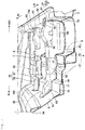
FIG. 1 is a plan view of a lower vehicle-body of an automobile having a vehicle-body structure according to an embodiment of the present invention. -
FIG. 2 is a perspective view of a first cross member and a second cross member of the lower vehicle-body as viewed from a vehicle front side toward a vehicle rear side. -
FIG. 3 is a sectional view of the first cross member in a vehicle width direction. -
FIG. 4 is an enlarged exploded perspective view showing components of the first cross member. -
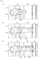
FIG. 5(a) is a perspective view showing an example of a fragile portion at a portion where a first member of the first cross member is mounted to a side sill,FIG. 5(B) is a perspective view showing a modification of the fragile portion, andFIG. 5(C) is a perspective view showing another modification of the fragile portion. -
FIG. 6 is a plan view showing a procedure for mounting the first cross member. -
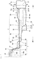
FIG. 7 is a sectional view of the second cross member in the vehicle width direction. -
FIG. 8 is an enlarged perspective view of a joining portion of a tunnel-side seat mounting bracket of the second cross member and a floor tunnel. -
FIG. 9 is an enlarged exploded perspective view showing how the tunnel-side seat mounting bracket of the second cross member is connected to the floor tunnel, a tunnel reinforcement, and a backbone frame. -
FIG. 10(a) is a sectional view along the line Xa-Xa inFIG. 9 , andFIG. 10(b) is a sectional view along the line Xb-Xb inFIG. 9 . - An embodiment of the present invention will be described below with reference to the accompanying drawings. Throughout the drawings, reference characters Fr and Rr respectively refer to a front side (or frontward) and a rear side (or rearward) of an automobile (i.e., vehicle), and reference characters OUT and IN respectively refer to an outside (or outward) and an inside (or inward) of the automobile in the vehicle width direction.
- The automobile or the vehicle may be a front-engine rear-drive (FR) vehicle or a four-wheel drive (4WD) vehicle having a propeller shaft and a longitudinally mounted engine.
-
FIG. 1 shows a lower vehicle-body 1 of the automobile having a vehicle-body structure of a vehicle according to an embodiment of the present invention. The lower vehicle-body 1 includes a pair of left andright side sills 2 extending in a vehicle front-rear direction, afloor tunnel 3 disposed at a center in the vehicle width direction between the pair of left andright side sills 2 and extending in the vehicle front-rear direction, andfloor panels 4 extending from vehicle-width-direction inner side ends of the pair of left andright side sills 2 toward a vehicle-width-direction inner side up to the floor tunnel 3 (i.e., toward a center of the automobile or vehicle). - A pair of left and right floor frames 5 each extending in the vehicle front-rear direction between a corresponding one of the pair of left and
right side sills 2 and thefloor tunnel 3 are disposed in the lower vehicle-body 1 each as a reinforcement member. Afirst cross member 6 and asecond cross member 7 laid between each one of the pair of left andright side sills 2 and thefloor tunnel 3 are disposed in this order toward the vehicle rear side. - An
oblique frame 8 extending obliquely rearward from each one of the pair of left andright side sills 2 to a corresponding one of the pair of left and right floor frames 5 is disposed frontward of thefirst cross member 6. Athird cross member 9 laid in the vehicle width direction between each one of the pair of left andright side sills 2 and thefloor tunnel 3 is disposed rearward of thesecond cross member 7. - Meanwhile, the lower vehicle-body 1 includes, in its front portion, a
dash panel 10a, adash panel cowl 10b, a pair of left and right front side frames 11, abumper reinforcement 12, afront cross member 13,apron members 14, asuspension housing 15, and the like. The lower vehicle-body 1 includes, in its rear portion, a pair of left and right rear side frames 16 extending from respective rear ends of the pair of left andright side sills 2 to the vehicle rear side, arear floor panel 17 extending in the vehicle width direction between the pair of left and right rear side frames 16, and arear cross member 18. Detailed description of theoblique frame 8, thethird cross member 9, and the front and rear components of the lower vehicle-body 1 has been omitted as they do not relate directly to the present invention. - As shown in
FIG. 3 , each of the pair of left andright side sills 2 is composed of a side sillinner panel 20 with a cross-section of a hat-shaped profile opening toward the vehicle-width-direction outer side and a side sillouter panel 21 with a cross-section of a hat-shaped profile opening toward the vehicle-width-direction inner side. - The side sill
inner panel 20 includes atop face 22, aside face 23 extending downward from a vehicle-width-direction inner side end of thetop face 22, abottom face 24 extending from a lower end of theside face 23 toward the vehicle-width-direction outer side, anupper ridge portion 25 between thetop face 22 and theside face 23, and alower ridge portion 26 between thebottom face 24 and theside face 23. Areinforcement plate 27 is fixed inside the side sillinner panel 20 at multiple positions in the vehicle front-rear direction, particularly positions overlapping thefirst cross member 6 and thesecond cross member 7 in the vehicle front-rear direction. - The side sill
outer panel 21 has a shape similar to that of the side sillinner panel 20 and facing the side sillinner panel 20. The side sillinner panel 20 and the side sillouter panel 21 are joined so as to form a substantially rectangular closed cross-section in the vehicle width direction. Lower portions of a hinge pillar supporting a front door and a center pillar supporting a rear door are joined to theside sill 2, though not shown in the figures. - As shown in
FIG. 1 , thefloor tunnel 3 extends in the vehicle front-rear direction from thedash panel 10a to thethird cross member 9. As shown inFIG. 2 , thefloor tunnel 3 has a hat-shaped profile opening downward and protruding upward in its cross-section in the vehicle width direction. Specifically, as shown inFIG. 3 , thefloor tunnel 3 is composed of aflange portion 30 joined to thefloor panel 4, awall rising portion 31 rising upward from theflange portion 30, a raisedportion 32 extending from thewall rising portion 31 toward the vehicle-width-direction inner side and positioned one step higher than theflange portion 30, aninclined wall portion 33 obliquely rising from the raisedportion 32 toward the center in the vehicle width direction, and atop plate portion 34. - The propeller shaft may be provided under or in the
floor tunnel 3 particularly in the cross sectional view of thefloor tunnel 3. - A pair of left and right backbone frames 35 is mounted on a top side of the
floor tunnel 3. Each of the pair of left and right backbone frames 35 has an inverted L-shaped cross-section in the vehicle width direction so as to form a closed cross-section with thetop plate portion 34 and theinclined wall portion 33 of thefloor tunnel 3 which thebackbone frame 35 faces. Anupper flange portion 36 and alower flange portion 37 are provided at respective ends in the vehicle width direction of thebackbone frame 35. Theupper flange portion 36 and thelower flange portion 37 are respectively joined to thetop plate portion 34 and theinclined wall portion 33 of thefloor tunnel 3. In particular, as shown inFIG. 9 , thelower flange portion 37 of thebackbone frame 35 is formed with multiple beads 38 (linearly extending recesses or projections formed by pressing a material) extending in the vehicle width direction at its portions joined to thefloor tunnel 3 at positions thereof overlapping thesecond cross member 7 in the vehicle front-rear direction. Themultiple beads 38 are joined to a tunnel reinforcement 100 (described later) through thefloor tunnel 3. - A
mount member 39a for supporting a rear portion of a transmission (not shown) is mounted to an underside of the raisedportion 32 on both sides of thefloor tunnel 3 in the vehicle width direction, and this restrains the decrease in vehicle-body rigidity that would otherwise occur due to thefirst cross members 6 on both sides being separated by thefloor tunnel 3. - Returning to
FIG. 3 , thefloor panel 4 extends from a vehicle-width-direction inner side end of theside sill 2 toward the vehicle-width-direction inner side, i.e., toward the center of the vehicle. In other words, a vehicle-width-direction outer side end of thefloor panel 4 is joined to theside face 23 of the side sillinner panel 20, and a vehicle-width-direction inner side end of thefloor panel 4 is joined to theflange portion 30 on both sides of thefloor tunnel 3 in the vehicle width direction. Also, thefloor panel 4 extends in the vehicle front-rear direction from thedash panel 10a to thethird cross member 9 inFIG. 1 . - The
floor panel 4 includes astep portion 40 provided at an approximate center between theside sill 2 and thefloor tunnel 3 and extending in the vehicle front-rear direction, afirst floor panel 41 on the vehicle-width-direction inner side of thestep portion 40, and asecond floor panel 42 on the vehicle-width-direction outer side of thestep portion 40. Thestep portion 40 is provided with afloor frame 5 described later. Thesecond floor panel 42 is formed at a position lower than thefirst floor panel 41. In other words, thesecond floor panel 42 located between a floor upper frame of the floor frame 43 and the side sill is formed at a position lower than the first floor panel located between the floor upper frame and thefloor tunnel 3. This allows a rectifier (not shown) to be only provided below thefirst floor panel 41 and eliminates the need for providing the rectifier below thesecond floor panel 42, helping reduce the area of the rectifier. - Each of the pair of left and right floor frames 5 is provided such that the
step portion 40 of thefloor panel 4 is interposed in thefloor frame 5 in an up-down direction, and extends in the vehicle front-rear direction. Thefloor frame 5 is composed of a floorupper frame 50 forming a closed cross-section jointly with a top side of thestep portion 40 of thefloor panel 4, and a floorlower frame 51 forming a closed cross-section jointly with an underside of thestep portion 40 of thefloor panel 4. - The floor
upper frame 50 includes a frametop face 50a facing thefirst floor panel 41, aframe side face 50b extending from a vehicle-width-direction inner side end of the frametop face 50a to thefirst floor panel 41, and aframe side face 50c extending from a vehicle-width-direction outer side end of the frametop face 50a to thesecond floor panel 42. The frametop face 50a of the floorupper frame 50 is provided at a position higher than a center position P between theupper ridge portion 25 and thelower ridge portion 26 of theside sill 2 in the up-down direction. A lower end of theframe side face 50b on the vehicle-width-direction inner side is joined to a top side of thefirst floor panel 41, and a lower end of theframe side face 50c on the vehicle-width-direction outer side is joined to a top side of thesecond floor panel 42. - The floor
lower frame 51 includes a framebottom face 51a facing thefirst floor panel 41, aframe side face 51b extending from a vehicle-width-direction inner side end of the framebottom face 51a to thefirst floor panel 41, and aframe side face 51c extending from a vehicle-width-direction outer side end of the framebottom face 51a to thesecond floor panel 42. The framebottom face 51a of the floorlower frame 51 is provided at substantially the same position as thesecond floor panel 42. An upper end of theframe side face 51b on the vehicle-width-direction inner side is joined to an underside of thefirst floor panel 41, and an upper end of theframe side face 51c on the vehicle-width-direction outer side is joined to an underside of thesecond floor panel 42. - The
first cross member 6 has or is composed of afirst member 61 on a side sill-side and asecond member 62 on a floor tunnel-side. Thefirst member 61 is mounted with a sill-sideseat mounting bracket 60, and thesecond member 62 is mounted with a tunnel-sideseat mounting bracket 63. The tunnel-sideseat mounting bracket 63 is provided at an inner end of thefirst cross member 6 in the vehicle-width-direction. - The
first member 61 extends from theside sill 2 to the frametop face 50a of the floorupper frame 50. As shown inFIG. 4 , thefirst member 61 has a hat-shaped cross-section in the vehicle front-rear direction and includes atop face 64 facing thefloor panel 4 and afront face 65 and arear face 66 extending from respective ends in the vehicle front-rear direction of thetop face 64 to thefloor panel 4. Thefront face 65 and therear face 66 respectively includes a frontlower portion 65A and a rearlower portion 66A at positions lower than thefirst floor panel 41. -
Flanges front face 65 and therear face 66 of thefirst member 61, and theflanges side face 23 of theside sill 2.Flanges 65b, 66b are provided to respective lower ends of thefront face 65 and therear face 66 of thefirst member 61, and theflanges 65b, 66b are joined to thesecond floor panel 42.Flanges front face 65 and therear face 66 of thefirst member 61, and theflanges 65c, 66c are joined to theframe side face 50c of the floorupper frame 50 and theflanges 65d, 66d are joined to the frametop face 50a of the floorupper frame 50. - The
top face 64 of thefirst member 61 includes, at its vehicle-width-direction outer side end, afragile portion 67 formed of a cutout. Thefragile portion 67 functions to transmit a side collision load to thetop face 64 of thefirst cross member 6 in the event of a side collision by cutting a part of the vehicle-width-direction outer side end of thetop face 64 of thefirst member 61 as shown inFIG. 5(a) and thereby allowing the vehicle-width-direction outer side end of thetop face 64 to be preferentially crushed under the side collision load. Besides the cutout, thefragile portion 67 may be a bead or a hole extending in the vehicle front-rear direction as shown inFIGS. 5(b) and 5(c) ; in short, thefragile portion 67 is only required to weaken the rigidity in the vehicle width direction of the vehicle-width-direction outer side end of the top face. - A recessed
bead 68 extending in the vehicle width direction is formed in each of thefront face 65 and therear face 66 of thefirst member 61. Preferably, thebeads 68 are provided above thesecond floor panel 42 and below the aforementioned center position P between theupper ridge portion 25 and thelower ridge portion 26 in the up-down direction of theside sill 2. Thebeads 68 increase the rigidity of thefront face 65 and therear face 66 of thefirst member 61 against the side collision load. - The
second member 62 extends from a vehicle-width-direction inner side end of thefirst member 61 to thefloor tunnel 3. As shown inFIG. 3 , thesecond member 62 has a hat-shaped cross-section in the vehicle front-rear direction and includes atop face 69 facing thefloor panel 4 and afront face 70 and arear face 71 extending from respective ends in the vehicle front-rear direction of thetop face 69 to thefloor panel 4. - A vehicle-width-direction outer side end of the
top face 69 of thesecond member 62 is positioned below a vehicle-width-direction inner side end of thetop face 64 of thefirst member 61 and, as shown inFIG. 3 , is overlapped with and joined to the vehicle-width-direction inner side end of thetop face 64 of thefirst member 61 to form a high-strength portion 72 that has a larger plate thickness than the frontlower portion 65A and the rearlower portion 66A of thefirst member 61 and thefront face 70 and therear face 71 of thesecond member 62 and is given a high strength.Flanges 70a, 71a are provided to respective lower ends of thefront face 70 and therear face 71 of thesecond member 62, and theflanges 70a, 71a are joined to thesecond floor panel 42. The vehicle-width-direction outer side end of thetop face 69 of thesecond member 62 extends to a joined portion of thefirst member 61 and the sill-sideseat mounting bracket 60, and this gives the high-strength portion 72 a higher strength than a high-strength portion 86 (described later) between thesecond member 62 and the tunnel-sideseat mounting bracket 63. - A recessed
bead 73 extending in the vehicle width direction is formed in thetop face 69 of thesecond member 62. Thebead 73 is provided so as to overlapbeads 78, 80 (described later) of the sill-sideseat mounting bracket 60 in the vehicle front-rear direction. - The sill-side
seat mounting bracket 60 is a fixing member for fixing a seat rail of the vehicle and is also a reinforcement member for reinforcing a sill-side end (or an outer end in the vehicle-width-direction) of thetop face 64 of thefirst member 61 of thefirst cross member 6. The sill-sideseat mounting bracket 60 includes atop face 74 facing thetop face 64 of thefirst member 61 and afront face 75 and arear face 76 extending from respective ends in the vehicle front-rear direction of thetop face 74 to thefloor panel 4. - A seat
rail mounting portion 77 protruding upward is formed at a center in the vehicle width direction of thetop face 74 of the sill-sideseat mounting bracket 60. A recessedbead 78 extending in the vehicle width direction is formed at an end of thetop face 74 on the outside of the seatrail mounting portion 77 of the sill-sideseat mounting bracket 60. A protrudingpiece 79 protruding to the vehicle-width-direction outer side is formed at a vehicle-width-direction outer side end of thetop face 74 of the sill-sideseat mounting bracket 60, and the protrudingpiece 79 abuts on and is joined to thetop face 22 of theside sill 2. An upward projectingbead 80 extending in the vehicle width direction is formed at an inner end of thetop face 74 of the sill-sideseat mounting bracket 60, and on both sides of thebead 80, the sill-sideseat mounting bracket 60 abuts on and is joined to thetop face 64 of thefirst member 61. - Multiple projecting
beads 81 extending in the up-down direction are formed in each of thefront face 75 and therear face 76 of the sill-sideseat mounting bracket 60, and on both sides of eachbead 81, thefront face 75 and therear face 76 abut on and are joined to thefront face 65 and therear face 66, respectively, of thefirst member 61.Flanges front face 75 and therear face 76 of the sill-sideseat mounting bracket 60, and theflanges side face 23 of theside sill 2. - The tunnel-side
seat mounting bracket 63 is a fixing member for fixing the seat rail of the vehicle. The tunnel-sideseat mounting bracket 63 extends from a vehicle-width-direction inner side end of thefloor panel 4 to theinclined wall portion 33 of thefloor tunnel 3. A vehicle-width-direction outer side half of the tunnel-sideseat mounting bracket 63 has a hat-shaped cross-section in the vehicle front-rear direction formed by atop face 82, afront face 83, and arear face 84. A seatrail mounting portion 85 protruding upward is formed on a top side of a vehicle-width-direction inner side half of the tunnel-sideseat mounting bracket 63. - A vehicle-width-direction outer side end of the tunnel-side
seat mounting bracket 63 is positioned below a vehicle-width-direction inner side end of thetop face 69 of thesecond member 62 and is overlapped with and joined to the vehicle-width-direction inner side end of thetop face 69 of thesecond member 62 to form, as shown inFIG. 3 , a high-strength portion 86 that has a larger plate thickness than the frontlower portion 65A and the rearlower portion 66A of thefirst member 61 and thefront face 70 and therear face 71 of thesecond member 62 and is given a high strength. - A
flange 82a is provided to a vehicle-width-direction inner side end of the tunnel-sideseat mounting bracket 63, and theflange 82a abuts on and is joined to theinclined wall portion 33 of thefloor tunnel 3. -
Flanges seat mounting bracket 63, and theflanges inclined wall portion 33 and the raisedportion 32, respectively, of thefloor tunnel 3.Flanges front face 83 and therear face 84, respectively, of the vehicle-width-direction outer side half of the tunnel-sideseat mounting bracket 63, and theflanges first floor panel 41. - In assembling the
first cross member 6, as shown inFIG. 6 , the tunnel-sideseat mounting bracket 63 is first mounted to thefloor tunnel 3, particularly from above, and then thesecond member 62 is mounted, particularly from above, so as to overlap a vehicle-width-direction outer side end of the tunnel-side seat mounting bracket 63 (FIG. 6(a) ). Then, a vehicle-width-direction inner side end of thefirst member 61 is overlapped with and mounted to a vehicle-width-direction outer side end of thesecond member 62, and a vehicle-width-direction outer side end of thefirst member 61 is mounted to the side sill 2 (FIG. 6(b) ). Finally, the sill-sideseat mounting bracket 60 is overlapped with and mounted to thefirst member 61, and a vehicle-width-direction outer side end of the sill-sideseat mounting bracket 60 is mounted to theside sill 2. Two adjacent members or all members may be sub-assembled in advance. - Similarly to the
first cross member 6, thesecond cross member 7 is composed of thefirst member 61 on the side sill-side and thesecond member 62 on the floor tunnel-side as shown inFIG. 7 , and thefirst member 61 is mounted with the sill-sideseat mounting bracket 60 and thesecond member 62 is mounted with the tunnel-sideseat mounting bracket 63. The tunnel-sideseat mounting bracket 63 is provided at an inner end of thesecond cross member 7 in the vehicle-width-direction. - The
second cross member 7 has a similar structure to that of the first cross member except that thesecond cross member 7 is positioned generally lower than thefirst cross member 6, the tunnel-sideseat mounting bracket 63 is composed of alower bracket 87 and anupper bracket 88, and atunnel reinforcement 100 is provided inside (or under) thefloor tunnel 3 to which the tunnel-sideseat mounting bracket 63 is mounted. Accordingly, description of equivalent parts has been omitted and only differences will be described below. - Because the
second cross member 7 is positioned generally lower than thefirst cross member 6, aflange 74a protruding upward is provided to a vehicle-width-direction outer side end of a top face of the sill-sideseat mounting bracket 60, and theflange 74a abuts on and is joined to theside face 23 of theside sill 2. - The tunnel-side
seat mounting bracket 63 of thesecond cross member 7 is composed of thelower bracket 87 and theupper bracket 88. - The
lower bracket 87 extends from the raisedportion 32 of thefloor tunnel 3 to the vehicle-width-direction inner side end of thefloor panel 4. As shown inFIG. 8 , a vehicle-width-direction outer side half of thelower bracket 87 has a hat-shaped cross-section in the vehicle front-rear direction formed by atop face 89, afront face 90, and arear face 91. - Via the raised
portion 32 of thefloor tunnel 3, thelower bracket 87 is bolted to both ends of atunnel member 39b that connects both ends in the vehicle width direction of thefloor tunnel 3, and this restrains the decrease in vehicle-body rigidity that would otherwise occur due to thesecond cross members 7 on both sides being separated by thefloor tunnel 3. - A vehicle-width-direction outer side end of the
lower bracket 87 is positioned below a vehicle-width-direction inner side end of thetop face 69 of thesecond member 62 and is overlapped with and joined to the vehicle-width-direction inner side end of thetop face 69 of thesecond member 62 to form a high-strength portion 92 that has a larger plate thickness than the frontlower portion 65A and the rearlower portion 66A of thefirst member 61 and thefront face 70 and therear face 71 of thesecond member 62 and is given a high strength. -
Flanges front face 90 and therear face 91 in the vehicle-width-direction outer side half of thelower bracket 87, and theflanges floor panel 4. An inner end and front-rear direction ends in the vehicle-width-direction inner side half of thelower bracket 87 abut on and are joined to the raisedportion 32 of thefloor tunnel 3. - The
upper bracket 88 is disposed above thelower bracket 87. Theupper bracket 88 is formed on its top side with a seatrail mounting portion 93 protruding upward. Aflange 88a is provided to a vehicle-width-direction outer side end of theupper bracket 88, and theflange 88a abuts on and is joined to thetop face 89 of thelower bracket 87. -
Flanges upper bracket 88, and theseflanges inclined wall portion 33 of thefloor tunnel 3 and are joined to the tunnel reinforcement 100 (described later) via theinclined wall portion 33. Also,flanges upper bracket 88, and theseflanges portion 32 of thefloor tunnel 3. - A
tunnel reinforcement 100 is mounted to an underside of thefloor tunnel 3 to which the tunnel-sideseat mounting bracket 63 of thesecond cross member 7 is joined. Thetunnel reinforcement 100 is substantially saddle-shaped with its cross-section in the vehicle width direction being in the form of an inverted U-shape opening downward. - As shown in
FIG. 10 , thetunnel reinforcement 100 includes afront projection 101, afront recess 102, arear projection 103, arear recess 104, and arear end projection 105 disposed in this order in the vehicle front-rear direction, and these are provided so as to extend in a circumferential direction. Therear projection 103 is formed, at its each end in the vehicle width direction, awide portion 106 that is wider than an intermediate portion of therear projection 103. Thefront recess 102 includes, on its each side in the vehicle width direction, anintermediate projection 107 that is provided so as to extend in the up-down direction along thefront projection 101 and therear projection 103. Afirst front recess 102a and a secondfront recess 102b are provided to respective ends in the vehicle front-rear direction of theintermediate projection 107. When viewed from inside thetunnel reinforcement 100, thefront projection 101, thefirst front recess 102a, theintermediate projection 107, the secondfront recess 102b, and therear projection 103 form a substantially W-shaped cross-section in the vehicle front-rear direction. Also, therear projection 103, therear recess 104, and therear end projection 105 form a substantially U-shaped cross-section in the vehicle front-rear direction. - The
tunnel reinforcement 100 is joined to the underside of thefloor tunnel 3 and, as explained below, also joined to thebackbone frame 35 and the tunnel-sideseat mounting bracket 63 via thefloor tunnel 3. - That is, as shown in
FIG. 10(a) , thefront projection 101, theintermediate projection 107, therear projection 103, and therear end projection 105 are respectively provided with a firstfront abutting portion 101a, a firstintermediate abutting portion 107a, a firstrear abutting portion 103a, and a first rearend abutting portion 105a that abut on and are welded to therespective beads 38 of thebackbone frame 35 via thefloor tunnel 3. - Also, as shown in
FIG. 10(b) , theintermediate projection 107 and therear projection 103 are respectively provided with a secondintermediate abutting portion 107b and a secondrear abutting portion 103b that abut on and are welded to theflange 88b of the tunnel-sideseat mounting bracket 63 via thefloor tunnel 3. Also, thefront projection 101 and thewide portion 106 of therear projection 103 are respectively provided with a secondfront abutting portion 101b and a thirdrear abutting portion 106a that respectively abut on and are welded to theflanges seat mounting bracket 63 via thefloor tunnel 3. - The
tunnel reinforcement 100 is provided with anextended portion 108 rearward of the tunnel-sideseat mounting bracket 63, and accordingly the length of thetunnel reinforcement 100 in the vehicle front-rear direction is longer than that of the tunnel-sideseat mounting bracket 63 of thesecond cross member 7. - Below a description will be given of functions of the
first cross member 6 and thesecond cross member 7 of the above-configured lower vehicle-body 1 according to the present embodiment in the event of a side collision. - In the lower vehicle-body 1 of the present embodiment, the
first cross member 6 and thesecond cross member 7 extending in the vehicle width direction receive a side collision load F that acts on theside sill 2 as shown inFIG. 1 when another vehicle collides with a side of the vehicle or when the side of the vehicle collides with an obstacle. This prevents a pillar (not shown) from intruding into a passenger compartment. - That is, as shown in
FIG. 3 , in thefirst cross member 6 in the lower vehicle-body 1 of the present embodiment, thetop face 64 of thefirst member 61 is joined to theside sill 2 via the sill-sideseat mounting bracket 60, the vehicle-width-direction inner side end of thetop face 64 of thefirst member 61 is joined to the vehicle-width-direction outer side end of thetop face 69 of thesecond member 62, and the vehicle-width-direction inner side end of thetop face 64 of thesecond member 62 is joined to a vehicle-width-direction outer side end of thetop face 82 of the tunnel-sideseat mounting bracket 63, and the tunnel-sideseat mounting bracket 63 is joined to the raisedportion 32 and theinclined wall portion 33 of thefloor tunnel 3. Thus, the top faces 64, 69, 74, and 82 of thefirst cross member 6 are joined to theside sill 2 and the floor tunnel 3 (the part A inFIG. 3 ) . - Also, in the
first cross member 6, the vehicle-width-direction outer side ends of thefront face 65 and therear face 66 of thefirst member 61 are joined to theside sill 2, and the vehicle-width-direction inner side ends of thefront face 65 and therear face 66 of thefirst member 61 are joined to the frametop face 50a of the floorupper frame 50 at a position higher than the center position P of theside sill 2 in the up-down direction (the part B inFIG. 3 ). - Thus, the
first cross member 6 can counteract a side collision load in the event of a side collision with its first bracing effect provided by the part A inFIG. 7 of the top faces 64, 69, 74, and 82 of the first cross member between theside sill 2 and thefloor tunnel 3 and with its second bracing effect provided by the part B inFIG. 7 of thefront face 65 and therear face 66 of thefirst member 61 between theside sill 2 and the frametop face 50a of the floorupper frame 50, resisting the inwardly falling motion of theside sill 2 toward the vehicle-width-direction inner side as shown by the arrow M inFIG. 3 . The same applies to thesecond cross member 7. Thus, even though the vehicle has a lowered floor including thesecond floor panel 42 lower than thefirst floor panel 41, thefirst cross member 6 and thesecond cross member 7 can effectively distribute and transfer the side collision load F in the vehicle width direction from theside sill 2 to the floorupper frame 50 and thefloor tunnel 3. - Further, the
bead 68 extending in the vehicle width direction is provided in each of thefront face 65 and therear face 66 of thefirst member 61 of the first cross member between theside sill 2 and theframe side face 50b. This prevents out-of-plane deformation (buckling) of thefront face 65 and therear face 66 and allows the side collision load F to be effectively supported by the bracing between theside sill 2 and the floorupper frame 50 in the event of a side collision, helping avoid stress concentration on thefloor tunnel 3 that may occur when the side collision load F is mainly supported by any bracing between theside sill 2 and thefloor tunnel 3. - Additionally, the top faces 64, 69, 74, and 82 of the
first cross member 6 connect the raisedportion 32 of thefloor tunnel 3 and theside sill 2, and thefront face 65 and therear face 66 of thefirst member 61 connect thewall rising portion 31 of thefloor tunnel 3 and theside sill 2. This allows the side collision load F to be received between theside sill 2 and each of thewall rising portion 31 and the raisedportion 32 of thefloor tunnel 3, helping avoid stress concentration on theinclined wall portion 33 and thetop plate portion 34, which constitute a main body of thefloor tunnel 3. - In the lower vehicle-body 1 of the present embodiment, the high-
strength portions lower portion 65A and the rearlower portion 66A of thefirst member 61 and given a high strength are provided to thefirst cross member 6 and thesecond cross member 7 at the overlapped portion of the sill-sideseat mounting bracket 60 and thetop face 64 of thefirst member 61, at the overlapped portion of thetop face 64 of thefirst member 61 and thetop face 69 of thesecond member 62, and at the overlapped portion of thetop face 69 of thesecond member 62 and the tunnel-sideseat mounting bracket 63. This allows the side collision load F, which is input to thefirst cross member 6 and thesecond cross member 7 so as to cause theside sill 2 to fall inward to the inside of the vehicle cabin in the event of a side collision, to be surely transmitted in the vehicle width direction via the high-strength portions front face 65 and therear face 66 of thefirst member 61 facing the loweredsecond floor panel 42. - Since the high-
strength portions first member 61, thesecond member 62, the sill-sideseat mounting bracket 60 and the tunnel-sideseat mounting bracket 63, the high-strength portions can be configured with a simple configuration. - The sill-side
seat mounting bracket 60 and the tunnel-sideseat mounting bracket 63 are respectively mounted to thefirst member 61 and thesecond member 62 having the high-strength portions seat mounting bracket 60 and the tunnel-sideseat mounting bracket 63 and reduces impact on an occupant sitting in the seat in the event of a side collision. - The sill-side
seat mounting bracket 60, thefirst member 61, thesecond member 62, and the tunnel-sideseat mounting bracket 63 are fixed to each other such that one closer to theside sill 2 lies on top of another adjacent one closer to thefloor tunnel 3. Accordingly, when the side collision load F causing inward falling deformation of theside sill 2 is input to thefirst cross member 6 and thesecond cross member 7, compressive force in the surface direction acts on the overlapped portion of each member, which can restrain peeling of the overlapped portion. - As shown in
FIG. 2 , thebead 73 on the top side of thesecond member 62 is provided so as to overlap thebeads seat mounting bracket 60 in the vehicle front-rear direction. This allows the side collision load F on theside sill 2 to be transmitted to the vehicle-width-direction inner side via thebeads seat mounting bracket 60 and thebead 73 of thesecond member 62. - In the lower vehicle-body 1 of the present embodiment, the
fragile portion 67 formed of a cutout extending in the vehicle front-rear direction is provided to a side-sill side end of thefirst member 61 at a position overlapping the sill-sideseat mounting bracket 60 in each of thefirst cross member 6 and thesecond cross member 7. - In the event of a side collision, due to the side collision load F being applied to the side sill, a moment M acts on the
side sill 2 so as to cause it to fall inward. Under this bending moment M, first, a proximal end of the protrudingpiece 79 of the sill-sideseat mounting bracket 60 joined to thetop face 22 of theside sill 2 experiences out-of-plane deformation. Because theseat mounting bracket 60 on the vehicle-width-direction inner side of the protrudingpiece 79 has high rigidity by virtue of its hat-shaped cross-section, the side collision is transmitted to thefragile portion 67 at the vehicle-width-direction outer side end of thetop face 64 of thefirst member 61. - Thus, the
fragile portion 67 of thefirst member 61 crushes and thereby absorbs energy of the side collision, restraining buckling deformation of thefirst cross member 6 and thesecond cross member 7 from occurring in their portions where such deformation is not intended to occur. Further, guiding the side collision load F preferentially in the direction in which thefragile portion 67 crushes allows to effectively distribute and transfer the side collision load F in the vehicle width direction. - Also, the sill-side
seat mounting bracket 60 as the reinforcement member is provided to the side sill-side end of thetop face 64 of thefirst member 61 of each of thefirst cross member 6 and thesecond cross member 7. Thus, the sill-sideseat mounting bracket 60 as the reinforcement member can receive a region including the crushedfragile portion 67 and thereby allows the side collision load F after crushing thefragile portion 67 to be transmitted in the vehicle width direction via the sill-sideseat mounting bracket 60 as the reinforcement member as well as thefirst member 61 and thesecond member 62. - The
fragile portion 67 is selected from a cutout, a bead, and a hole. Hence, thefragile portion 67 can be formed by simple processing and also its deformation behavior in the event of a side collision can be controlled. - The reinforcement member is the sill-side
seat mounting bracket 60, and thefragile portion 67 is positioned on the vehicle-width-direction outer side of the seatrail mounting portion 77 of the sill-sideseat mounting bracket 60. Hence, even when thefragile portion 67 is crushed and deformed in the event of a side collision, it does not reach the seatrail mounting portion 77 of the sill-sideseat mounting bracket 60, and thus impact on an occupant sitting on the seat can be reduced. - The
fragile portion 67 is provided only on thetop face 64 at the side sill-side end of thefirst member 61. Hence, ridge portions between thetop face 64 and thefront face 65 and between thetop face 64 and therear face 66 remain uncrushed in the event of a side collision, allowing the side collision load F to be transmitted in the vehicle width direction. - In the lower vehicle-body 1 of the present embodiment, as shown in
FIG. 9 , thetunnel reinforcement 100 is fixed at its secondfront abutting portion 101b, secondintermediate abutting portion 107b, secondrear abutting portion 103b, and thirdrear abutting portion 106a to the tunnel-sideseat mounting bracket 63 via thefloor tunnel 3. Also, thetunnel reinforcement 100 is fixed at its firstfront abutting portion 101a, firstintermediate abutting portion 107a, and firstrear abutting portion 103a to themultiple beads 38 of thebackbone frame 35 via thefloor tunnel 3. Thus, the side collision load F input from thesecond cross member 7 to the tunnel-sideseat mounting bracket 63 in the event of a side collision is transmitted to thetunnel reinforcement 100 via the secondfront abutting portion 101b, the secondintermediate abutting portion 107b, the secondrear abutting portion 103b, and the thirdrear abutting portion 106a of thetunnel reinforcement 100 and further can be transmitted to themultiple beads 38 of thebackbone frame 35 via the firstfront abutting portion 101a, the firstintermediate abutting portion 107a, and the firstrear abutting portion 103a of thetunnel reinforcement 100. This restrains deformation of thetunnel reinforcement 100 as well as thefloor tunnel 3. - Additionally, ridges of the first
front abutting portion 101a, the firstintermediate abutting portion 107a, and the firstrear abutting portion 103a of thetunnel reinforcement 100 and ridges of thebeads 38 of thebackbone frame 35 are in contact with each other. This allows the side collision load F to be surely transmitted to themultiple beads 38 of thebackbone frame 35 via the firstfront abutting portion 101a, the firstintermediate abutting portion 107a, and the firstrear abutting portion 103a of thetunnel reinforcement 100. - The
tunnel reinforcement 100 includes, respectively in thefront projection 101, theintermediate projection 107, and therear projection 103, the firstfront abutting portion 101a, the firstintermediate abutting portion 107a, and the firstrear abutting portion 103a that abut on the respectivemultiple beads 38 of thebackbone frame 35, and includes the secondfront abutting portion 102a, the secondintermediate abutting portion 107b, the secondrear abutting portion 103b, and the thirdrear abutting portion 106a that abut on theseat mounting bracket 63. This allows for easy and reliable joining of thetunnel reinforcement 100 and thebackbone frame 35 and of thetunnel reinforcement 100 and theseat mounting bracket 63 via these abutting portions. - The
tunnel reinforcement 100 includes, respectively between thefront projection 101 and theintermediate projection 107 and between theintermediate projection 107 and therear projection 103, thefront recess 102a and therear recess 102b protruding in a direction away from the underside of thefloor tunnel 3. Thetunnel reinforcement 100 further includes therear end recess 104 protruding in the direction away from the underside of thefloor tunnel 3 between therear projection 103 and therear end projection 105. These continuous projections and recesses can increase the rigidity of thetunnel reinforcement 100. - The
tunnel reinforcement 100 includes theextended portion 108 rearward of therear abutting portion 103, and theextended portion 108 includes, at its rear end, arear end projection 105 fixed to theadditional bead 38 of thebackbone frame 35. Thistunnel reinforcement 100 elongated in the vehicle front-rear direction by virtue of itsextended portion 108 increases the rigidity of thefloor tunnel 3, which as a result allows to surely restrain deformation of thefloor tunnel 3 even when the side collision load F is input from theseat mounting bracket 63 to the front portion of thetunnel reinforcement 100. - The present invention is not limited to the above embodiment and may be modified in various ways without departing from the scope of the present invention.
- For example, although the tunnel-side
seat mounting bracket 63 of thesecond cross member 7 is composed of thelower bracket 87 and theupper bracket 88, it may be composed of a single component similarly to the tunnel-sideseat mounting bracket 63 of thefirst cross member 6. Conversely, the tunnel-sideseat mounting bracket 63 of thefirst cross member 6 may be composed of thelower bracket 87 and theupper bracket 88 similarly to the tunnel-sideseat mounting bracket 63 of thesecond cross member 7. -
- 1
- Lower vehicle-body
- 2
- Side sill
- 3
- Floor tunnel
- 4
- Floor panel
- 5
- Floor frame
- 6
- First cross member
- 7
- Second cross member
- 22
- Top face
- 23
- Side face
- 24
- Bottom face
- 25
- Upper ridge portion
- 26
- Lower ridge portion
- 31
- Wall rising portion
- 32
- raised portion
- 35
- backbone frame
- 38
- bead
- 40
- step portion
- 41
- first floor panel
- 42
- second floor panel
- 50
- floor upper frame
- 50a
- frame top face
- 50b
- frame side face
- 50c
- frame side face
- 60
- sill-side seat mounting bracket
- 61
- first member
- 62
- second member
- 63
- tunnel-side seat mounting bracket
- 64
- top face
- 65
- front face
- 65A
- front lower portion
- 66
- rear face
- 66A
- rear lower portion
- 67
- fragile portion
- 68
- bead
- 69
- top face
- 70
- front face
- 71
- rear face
- 72
- high-strength portion
- 73
- bead
- 78
- bead
- 80
- bead
- 86
- high-strength portion
- 92
- high-strength portion
- 100
- tunnel reinforcement
- 101
- front projection
- 103
- rear projection
- 107
- intermediate projection
- 108
- extended portion
- 101a
- first front abutting portion
- 107a
- first intermediate abutting portion
- 103a
- first rear abutting portion
- 101b
- second front abutting portion
- 107b
- second intermediate abutting portion
- 103b
- second rear abutting portion
- 106a
- third rear abutting portion
Claims (15)
- A vehicle-body structure comprising:a pair of left and right side sills (2) extending in a front-rear direction of a vehicle;floor panels (4) extending from vehicle-width-direction inner side ends of the side sills (2) toward a vehicle-width-direction inner side or a center of the vehicle;a floor tunnel (3) connecting vehicle-width-direction inner side ends of the floor panels (4) and having a shape protruding upward;a pair of left and right cross members (6, 7) connecting the side sills (2) and the floor tunnel (3);seat mounting brackets (63) mounted to ends in a vehicle width direction of the cross members (6, 7);a pair of left and right backbone frames (35) facing a top and a side of the floor tunnel (3) and fixed to the floor tunnel (3), the pair of left and right backbone frames (35) extending in a vehicle front-rear direction; anda tunnel reinforcement (100) having a front projection (101), an intermediate projection (107), and a rear projection (103) abutting on an underside of the floor tunnel (3), whereinthe backbone frame (35) includes a plurality of beads (38) abutting on the floor tunnel (3), andthe tunnel reinforcement (100) is fixed at the front projection (101), the intermediate projection (107), and the rear projection (103) to the seat mounting bracket (63) via the floor tunnel (3) and is also fixed to the plurality of beads (38) of the backbone frame (35) via the floor tunnel (3).
- The vehicle-body structure according to claim 1, wherein
the seat mounting brackets (63) are fixed to the floor tunnel (3) and the cross members (6, 7), respectively. - The vehicle-body structure according to claim 1 or 2, wherein
ridges of the front projection (101), the intermediate projection (107), and the rear projection (103) of the tunnel reinforcement (100) and ridges of the beads (38) of the backbone frame (35) are in contact with each other. - The vehicle-body structure according to any one of the preceding claims, further comprising:
a first front abutting portion (101a), a first intermediate abutting portion (107a), and a first rear abutting portion (103a) abutting on the plurality of beads (38) of the backbone frame (35) respectively at the front projection (101), the intermediate projection (107), and the rear projection (103). - The vehicle-body structure according to any one of the preceding claims, further comprising:
a second front abutting portion (101b), a second intermediate abutting portion (107b), and a second rear abutting portion (103b) abutting on the seat mounting bracket (63). - The vehicle-body structure according to any one of the preceding claims, further comprising a front recess (102a) and a rear recess (102b) protruding or concaved in a direction away from the underside of the floor tunnel (3) respectively between the front projection (101) and the intermediate projection (107) and between the intermediate projection (107) and the rear projection (103) .
- The vehicle-body structure according to any one of the preceding claims, wherein
the tunnel reinforcement (100) includes an extended portion (108) rearward of the rear abutting portion (103a, 103b). - The vehicle-body structure according to claim 6, wherein
the extended portion (108) includes, at a rear end thereof, a rear end projection (105) fixed to an additional bead of the backbone frame (35). - The vehicle-body structure according to claim 8, further comprising a rear end recess (104) protruding or concaved in a direction away from the underside of the floor tunnel (3) between the rear projection (103) and the rear end projection (105).
- The vehicle-body structure of according to any one of the preceding claims, wherein
backbone frames (35) are arranged above the seat mounting brackets (63). - A vehicle comprising the vehicle-body structure according to any one of the preceding claims.
- The vehicle according to claim 11 further comprising a seat configured to be mounted on the seat mounting bracket (63).
- The vehicle according to claim 11 or 12 further comprising a propeller shaft.
- The vehicle according to claim 13, wherein
the propeller shaft is disposed under or in the floor tunnel (3). - The vehicle according to any one of claims 11 to 14 further comprising a longitudinally mounted engine.
Applications Claiming Priority (1)
| Application Number | Priority Date | Filing Date | Title |
|---|---|---|---|
| JP2019165100A JP7316513B2 (en) | 2019-09-11 | 2019-09-11 | vehicle body structure |
Publications (2)
| Publication Number | Publication Date |
|---|---|
| EP3792155A1 true EP3792155A1 (en) | 2021-03-17 |
| EP3792155B1 EP3792155B1 (en) | 2022-06-22 |
Family
ID=72322336
Family Applications (1)
| Application Number | Title | Priority Date | Filing Date |
|---|---|---|---|
| EP20193808.1A Active EP3792155B1 (en) | 2019-09-11 | 2020-09-01 | Vehicle-body structure, and vehicle |
Country Status (4)
| Country | Link |
|---|---|
| US (1) | US11383770B2 (en) |
| EP (1) | EP3792155B1 (en) |
| JP (1) | JP7316513B2 (en) |
| CN (1) | CN112477989B (en) |
Cited By (1)
| Publication number | Priority date | Publication date | Assignee | Title |
|---|---|---|---|---|
| WO2024146986A1 (en) * | 2023-01-05 | 2024-07-11 | Stellantis Auto Sas | Reinforcing part for a motor vehicle underbody |
Families Citing this family (20)
| Publication number | Priority date | Publication date | Assignee | Title |
|---|---|---|---|---|
| JP7040469B2 (en) * | 2019-01-23 | 2022-03-23 | マツダ株式会社 | Rear body structure of the vehicle |
| CN112937697B (en) * | 2021-03-18 | 2022-08-26 | 东风柳州汽车有限公司 | Longeron additional strengthening and car |
| JP7604985B2 (en) * | 2021-03-29 | 2024-12-24 | マツダ株式会社 | Body structure |
| JP7376528B2 (en) * | 2021-03-31 | 2023-11-08 | トヨタ自動車株式会社 | car body |
| JP7676920B2 (en) * | 2021-04-30 | 2025-05-15 | マツダ株式会社 | Vehicle underbody structure |
| US12030479B1 (en) | 2021-08-13 | 2024-07-09 | Oshkosh Defense, Llc | Prioritized charging of an energy storage system of a military vehicle |
| US12311754B1 (en) | 2021-08-13 | 2025-05-27 | Oshkosh Defense, Llc | Power export system for a military vehicle |
| US11498409B1 (en) * | 2021-08-13 | 2022-11-15 | Oshkosh Defense, Llc | Electrified military vehicle |
| US12351028B1 (en) | 2021-08-13 | 2025-07-08 | Oshkosh Defense, Llc | Military vehicle with modular battery units |
| US12319160B1 (en) | 2021-08-13 | 2025-06-03 | Oshkosh Defense, Llc | Convoy operations for electrified military vehicles |
| US12130122B1 (en) | 2021-08-13 | 2024-10-29 | Oshkosh Defense, Llc | Military vehicle with battery armor |
| US11485228B1 (en) | 2021-08-13 | 2022-11-01 | Oshkosh Defense, Llc | Electrified military vehicle |
| US12083995B1 (en) | 2021-08-13 | 2024-09-10 | Oshkosh Defense, Llc | Power export system for a military vehicle |
| US12358361B1 (en) | 2021-08-13 | 2025-07-15 | Oshkosh Defense, Llc | Electrified military vehicle with electric weaponry support system |
| US12583309B1 (en) | 2021-08-13 | 2026-03-24 | Oshkosh Defense, Llc | Hybrid power system for a military vehicle |
| US12060053B1 (en) | 2021-08-13 | 2024-08-13 | Oshkosh Defense, Llc | Military vehicle with control modes |
| JP7779049B2 (en) * | 2021-09-09 | 2025-12-03 | スズキ株式会社 | Body floor structure |
| KR20240022837A (en) * | 2022-08-12 | 2024-02-20 | 현대자동차주식회사 | Floor structure for electric vehicle |
| CN118683636A (en) * | 2023-03-21 | 2024-09-24 | 本田技研工业株式会社 | Seat mounting structure |
| FR3160151A1 (en) * | 2024-03-18 | 2025-09-19 | Stellantis Auto Sas | MOTOR VEHICLE UNDERBODY WITH REINFORCED RIGIDITY IN A MEDIAN LONGITUDINAL ZONE |
Citations (5)
| Publication number | Priority date | Publication date | Assignee | Title |
|---|---|---|---|---|
| JPH07165125A (en) * | 1993-12-10 | 1995-06-27 | Mazda Motor Corp | Seat bracket mounting structure |
| JP2015134520A (en) | 2014-01-16 | 2015-07-27 | トヨタ自動車株式会社 | Lower body structure |
| US20170113729A1 (en) * | 2015-10-22 | 2017-04-27 | Toyota Jidosha Kabushiki Kaisha | Vehicle floor portion structure |
| US20190009832A1 (en) * | 2017-07-06 | 2019-01-10 | Mazda Motor Corporation | Lower vehicle-body structure of automotive vehicle |
| EP3508400A1 (en) * | 2017-12-28 | 2019-07-10 | Mazda Motor Corporation | Vehicle body structure, vehicle, mount member, and method of manufacturing |
Family Cites Families (22)
| Publication number | Priority date | Publication date | Assignee | Title |
|---|---|---|---|---|
| JPS5673977U (en) * | 1979-11-13 | 1981-06-17 | ||
| JP4207806B2 (en) * | 2004-03-02 | 2009-01-14 | 日産自動車株式会社 | Body floor structure |
| JP4747812B2 (en) * | 2005-12-01 | 2011-08-17 | マツダ株式会社 | Lower body structure of the vehicle |
| DE102006031452A1 (en) | 2006-07-07 | 2008-01-17 | Dr.Ing.H.C. F. Porsche Ag | Transverse bridge for stiffening the tunnel area of a floor structure of a motor vehicle |
| JP4286884B2 (en) * | 2007-06-28 | 2009-07-01 | 本田技研工業株式会社 | Auto body structure |
| CN104340282B (en) * | 2014-10-23 | 2017-09-12 | 奇瑞汽车股份有限公司 | A kind of automobile batteries protection structure |
| JP6277948B2 (en) * | 2014-12-05 | 2018-02-14 | マツダ株式会社 | Lower body structure of automobile |
| JP6485200B2 (en) | 2015-05-12 | 2019-03-20 | スズキ株式会社 | Vehicle floor structure |
| JP6484140B2 (en) | 2015-08-05 | 2019-03-13 | 本田技研工業株式会社 | Vehicle side collision detection assembly |
| WO2017098305A1 (en) * | 2015-12-09 | 2017-06-15 | Arcelormittal | Vehicle underbody structure comprising a transversal beam of varying resistance to plastic deformation |
| JP2019177705A (en) * | 2016-07-11 | 2019-10-17 | 本田技研工業株式会社 | Vehicle body substructure |
| JP6597562B2 (en) * | 2016-11-08 | 2019-10-30 | トヨタ自動車株式会社 | Vehicle lower structure |
| EP3578444A4 (en) * | 2017-03-10 | 2020-03-04 | Mazda Motor Corporation | Lower vehicle body structure for vehicle |
| JP6977497B2 (en) * | 2017-11-15 | 2021-12-08 | トヨタ自動車株式会社 | Vehicle side structure |
| JP6881326B2 (en) | 2018-01-16 | 2021-06-02 | マツダ株式会社 | Lower body structure |
| JP6915592B2 (en) * | 2018-06-15 | 2021-08-04 | マツダ株式会社 | Lower body structure |
| JP6881396B2 (en) * | 2018-06-15 | 2021-06-02 | マツダ株式会社 | Lower body structure |
| US11091016B2 (en) * | 2019-03-06 | 2021-08-17 | Mazda Motor Corporation | Lower vehicle-body structure of vehicle |
| CN111942480B (en) * | 2019-05-15 | 2022-11-22 | 马自达汽车株式会社 | Lower vehicle body structure of electric vehicle |
| JP7275836B2 (en) * | 2019-05-15 | 2023-05-18 | マツダ株式会社 | Lower body structure of electric vehicle |
| JP7318323B2 (en) * | 2019-06-07 | 2023-08-01 | マツダ株式会社 | vehicle underbody structure |
| JP7395887B2 (en) * | 2019-09-03 | 2023-12-12 | マツダ株式会社 | Vehicle front body structure |
-
2019
- 2019-09-11 JP JP2019165100A patent/JP7316513B2/en active Active
-
2020
- 2020-07-30 CN CN202010748757.4A patent/CN112477989B/en active Active
- 2020-08-31 US US17/008,511 patent/US11383770B2/en active Active
- 2020-09-01 EP EP20193808.1A patent/EP3792155B1/en active Active
Patent Citations (6)
| Publication number | Priority date | Publication date | Assignee | Title |
|---|---|---|---|---|
| JPH07165125A (en) * | 1993-12-10 | 1995-06-27 | Mazda Motor Corp | Seat bracket mounting structure |
| JP2015134520A (en) | 2014-01-16 | 2015-07-27 | トヨタ自動車株式会社 | Lower body structure |
| US20170113729A1 (en) * | 2015-10-22 | 2017-04-27 | Toyota Jidosha Kabushiki Kaisha | Vehicle floor portion structure |
| US20190009832A1 (en) * | 2017-07-06 | 2019-01-10 | Mazda Motor Corporation | Lower vehicle-body structure of automotive vehicle |
| JP2019014354A (en) | 2017-07-06 | 2019-01-31 | マツダ株式会社 | Lower body structure of automobile |
| EP3508400A1 (en) * | 2017-12-28 | 2019-07-10 | Mazda Motor Corporation | Vehicle body structure, vehicle, mount member, and method of manufacturing |
Cited By (2)
| Publication number | Priority date | Publication date | Assignee | Title |
|---|---|---|---|---|
| WO2024146986A1 (en) * | 2023-01-05 | 2024-07-11 | Stellantis Auto Sas | Reinforcing part for a motor vehicle underbody |
| FR3144800A1 (en) * | 2023-01-05 | 2024-07-12 | Psa Automobiles Sa | REINFORCEMENT PART FOR A MOTOR VEHICLE UNDERBODY |
Also Published As
| Publication number | Publication date |
|---|---|
| JP7316513B2 (en) | 2023-07-28 |
| CN112477989B (en) | 2023-03-14 |
| US11383770B2 (en) | 2022-07-12 |
| JP2021041818A (en) | 2021-03-18 |
| CN112477989A (en) | 2021-03-12 |
| EP3792155B1 (en) | 2022-06-22 |
| US20210070375A1 (en) | 2021-03-11 |
Similar Documents
| Publication | Publication Date | Title |
|---|---|---|
| EP3792155B1 (en) | Vehicle-body structure, and vehicle | |
| EP3792154A1 (en) | Vehicle-body structure, and vehicle | |
| AU705222B2 (en) | Front structure of car body, and method of absorbing impact by means of the front structure | |
| US8292356B2 (en) | Lower vehicle-body structure of vehicle | |
| CN101332837B (en) | Vehicle body structure | |
| EP1985527B1 (en) | Front structure of automotive vehicle | |
| US8939496B2 (en) | Vehicle structure | |
| EP2783951B1 (en) | Vehicle body superstructure | |
| EP4588760A1 (en) | Vehicle lower body structure and vehicle | |
| JP2021041816A (en) | Vehicle body structure | |
| JP7751235B2 (en) | Body structure | |
| EP4588761A1 (en) | Vehicle lower body structure and vehicle | |
| US11591025B2 (en) | Front vehicle-body structure of vehicle | |
| US11554811B2 (en) | Vehicle lower body structure | |
| KR20230139223A (en) | Vehicle body structure | |
| JPS6320619Y2 (en) | ||
| JP2021041815A (en) | Vehicle body structure | |
| CN111674472B (en) | Vehicle front structure | |
| EP4588759A1 (en) | Vehicle lower body structure and vehicle | |
| CN120681234A (en) | Body structure and vehicle | |
| CN114466786A (en) | Floor reinforcement structure of vehicle | |
| CN118871344A (en) | Vehicle body structure and vehicle body structure design method | |
| JPH11105738A (en) | Car body structure | |
| JPS61249876A (en) | Cowl structure for automobile |
Legal Events
| Date | Code | Title | Description |
|---|---|---|---|
| PUAI | Public reference made under article 153(3) epc to a published international application that has entered the european phase |
Free format text: ORIGINAL CODE: 0009012 |
|
| STAA | Information on the status of an ep patent application or granted ep patent |
Free format text: STATUS: THE APPLICATION HAS BEEN PUBLISHED |
|
| AK | Designated contracting states |
Kind code of ref document: A1 Designated state(s): AL AT BE BG CH CY CZ DE DK EE ES FI FR GB GR HR HU IE IS IT LI LT LU LV MC MK MT NL NO PL PT RO RS SE SI SK SM TR |
|
| AX | Request for extension of the european patent |
Extension state: BA ME |
|
| STAA | Information on the status of an ep patent application or granted ep patent |
Free format text: STATUS: REQUEST FOR EXAMINATION WAS MADE |
|
| 17P | Request for examination filed |
Effective date: 20210826 |
|
| RBV | Designated contracting states (corrected) |
Designated state(s): AL AT BE BG CH CY CZ DE DK EE ES FI FR GB GR HR HU IE IS IT LI LT LU LV MC MK MT NL NO PL PT RO RS SE SI SK SM TR |
|
| GRAP | Despatch of communication of intention to grant a patent |
Free format text: ORIGINAL CODE: EPIDOSNIGR1 |
|
| STAA | Information on the status of an ep patent application or granted ep patent |
Free format text: STATUS: GRANT OF PATENT IS INTENDED |
|
| INTG | Intention to grant announced |
Effective date: 20220118 |
|
| GRAS | Grant fee paid |
Free format text: ORIGINAL CODE: EPIDOSNIGR3 |
|
| GRAA | (expected) grant |
Free format text: ORIGINAL CODE: 0009210 |
|
| STAA | Information on the status of an ep patent application or granted ep patent |
Free format text: STATUS: THE PATENT HAS BEEN GRANTED |
|
| AK | Designated contracting states |
Kind code of ref document: B1 Designated state(s): AL AT BE BG CH CY CZ DE DK EE ES FI FR GB GR HR HU IE IS IT LI LT LU LV MC MK MT NL NO PL PT RO RS SE SI SK SM TR |
|
| REG | Reference to a national code |
Ref country code: GB Ref legal event code: FG4D |
|
| REG | Reference to a national code |
Ref country code: CH Ref legal event code: EP |
|
| REG | Reference to a national code |
Ref country code: DE Ref legal event code: R096 Ref document number: 602020003651 Country of ref document: DE |
|
| REG | Reference to a national code |
Ref country code: AT Ref legal event code: REF Ref document number: 1499617 Country of ref document: AT Kind code of ref document: T Effective date: 20220715 |
|
| REG | Reference to a national code |
Ref country code: IE Ref legal event code: FG4D |
|
| REG | Reference to a national code |
Ref country code: LT Ref legal event code: MG9D |
|
| REG | Reference to a national code |
Ref country code: NL Ref legal event code: MP Effective date: 20220622 |
|
| PG25 | Lapsed in a contracting state [announced via postgrant information from national office to epo] |
Ref country code: SE Free format text: LAPSE BECAUSE OF FAILURE TO SUBMIT A TRANSLATION OF THE DESCRIPTION OR TO PAY THE FEE WITHIN THE PRESCRIBED TIME-LIMIT Effective date: 20220622 Ref country code: NO Free format text: LAPSE BECAUSE OF FAILURE TO SUBMIT A TRANSLATION OF THE DESCRIPTION OR TO PAY THE FEE WITHIN THE PRESCRIBED TIME-LIMIT Effective date: 20220922 Ref country code: LT Free format text: LAPSE BECAUSE OF FAILURE TO SUBMIT A TRANSLATION OF THE DESCRIPTION OR TO PAY THE FEE WITHIN THE PRESCRIBED TIME-LIMIT Effective date: 20220622 Ref country code: HR Free format text: LAPSE BECAUSE OF FAILURE TO SUBMIT A TRANSLATION OF THE DESCRIPTION OR TO PAY THE FEE WITHIN THE PRESCRIBED TIME-LIMIT Effective date: 20220622 Ref country code: GR Free format text: LAPSE BECAUSE OF FAILURE TO SUBMIT A TRANSLATION OF THE DESCRIPTION OR TO PAY THE FEE WITHIN THE PRESCRIBED TIME-LIMIT Effective date: 20220923 Ref country code: FI Free format text: LAPSE BECAUSE OF FAILURE TO SUBMIT A TRANSLATION OF THE DESCRIPTION OR TO PAY THE FEE WITHIN THE PRESCRIBED TIME-LIMIT Effective date: 20220622 Ref country code: BG Free format text: LAPSE BECAUSE OF FAILURE TO SUBMIT A TRANSLATION OF THE DESCRIPTION OR TO PAY THE FEE WITHIN THE PRESCRIBED TIME-LIMIT Effective date: 20220922 |
|
| REG | Reference to a national code |
Ref country code: AT Ref legal event code: MK05 Ref document number: 1499617 Country of ref document: AT Kind code of ref document: T Effective date: 20220622 |
|
| PG25 | Lapsed in a contracting state [announced via postgrant information from national office to epo] |
Ref country code: RS Free format text: LAPSE BECAUSE OF FAILURE TO SUBMIT A TRANSLATION OF THE DESCRIPTION OR TO PAY THE FEE WITHIN THE PRESCRIBED TIME-LIMIT Effective date: 20220622 Ref country code: LV Free format text: LAPSE BECAUSE OF FAILURE TO SUBMIT A TRANSLATION OF THE DESCRIPTION OR TO PAY THE FEE WITHIN THE PRESCRIBED TIME-LIMIT Effective date: 20220622 |
|
| PG25 | Lapsed in a contracting state [announced via postgrant information from national office to epo] |
Ref country code: NL Free format text: LAPSE BECAUSE OF FAILURE TO SUBMIT A TRANSLATION OF THE DESCRIPTION OR TO PAY THE FEE WITHIN THE PRESCRIBED TIME-LIMIT Effective date: 20220622 |
|
| PG25 | Lapsed in a contracting state [announced via postgrant information from national office to epo] |
Ref country code: SM Free format text: LAPSE BECAUSE OF FAILURE TO SUBMIT A TRANSLATION OF THE DESCRIPTION OR TO PAY THE FEE WITHIN THE PRESCRIBED TIME-LIMIT Effective date: 20220622 Ref country code: SK Free format text: LAPSE BECAUSE OF FAILURE TO SUBMIT A TRANSLATION OF THE DESCRIPTION OR TO PAY THE FEE WITHIN THE PRESCRIBED TIME-LIMIT Effective date: 20220622 Ref country code: RO Free format text: LAPSE BECAUSE OF FAILURE TO SUBMIT A TRANSLATION OF THE DESCRIPTION OR TO PAY THE FEE WITHIN THE PRESCRIBED TIME-LIMIT Effective date: 20220622 Ref country code: PT Free format text: LAPSE BECAUSE OF FAILURE TO SUBMIT A TRANSLATION OF THE DESCRIPTION OR TO PAY THE FEE WITHIN THE PRESCRIBED TIME-LIMIT Effective date: 20221024 Ref country code: ES Free format text: LAPSE BECAUSE OF FAILURE TO SUBMIT A TRANSLATION OF THE DESCRIPTION OR TO PAY THE FEE WITHIN THE PRESCRIBED TIME-LIMIT Effective date: 20220622 Ref country code: EE Free format text: LAPSE BECAUSE OF FAILURE TO SUBMIT A TRANSLATION OF THE DESCRIPTION OR TO PAY THE FEE WITHIN THE PRESCRIBED TIME-LIMIT Effective date: 20220622 Ref country code: CZ Free format text: LAPSE BECAUSE OF FAILURE TO SUBMIT A TRANSLATION OF THE DESCRIPTION OR TO PAY THE FEE WITHIN THE PRESCRIBED TIME-LIMIT Effective date: 20220622 Ref country code: AT Free format text: LAPSE BECAUSE OF FAILURE TO SUBMIT A TRANSLATION OF THE DESCRIPTION OR TO PAY THE FEE WITHIN THE PRESCRIBED TIME-LIMIT Effective date: 20220622 |
|
| PG25 | Lapsed in a contracting state [announced via postgrant information from national office to epo] |
Ref country code: PL Free format text: LAPSE BECAUSE OF FAILURE TO SUBMIT A TRANSLATION OF THE DESCRIPTION OR TO PAY THE FEE WITHIN THE PRESCRIBED TIME-LIMIT Effective date: 20220622 Ref country code: IS Free format text: LAPSE BECAUSE OF FAILURE TO SUBMIT A TRANSLATION OF THE DESCRIPTION OR TO PAY THE FEE WITHIN THE PRESCRIBED TIME-LIMIT Effective date: 20221022 |
|
| REG | Reference to a national code |
Ref country code: DE Ref legal event code: R097 Ref document number: 602020003651 Country of ref document: DE |
|
| PG25 | Lapsed in a contracting state [announced via postgrant information from national office to epo] |
Ref country code: AL Free format text: LAPSE BECAUSE OF FAILURE TO SUBMIT A TRANSLATION OF THE DESCRIPTION OR TO PAY THE FEE WITHIN THE PRESCRIBED TIME-LIMIT Effective date: 20220622 |
|
| PG25 | Lapsed in a contracting state [announced via postgrant information from national office to epo] |
Ref country code: MC Free format text: LAPSE BECAUSE OF FAILURE TO SUBMIT A TRANSLATION OF THE DESCRIPTION OR TO PAY THE FEE WITHIN THE PRESCRIBED TIME-LIMIT Effective date: 20220622 Ref country code: DK Free format text: LAPSE BECAUSE OF FAILURE TO SUBMIT A TRANSLATION OF THE DESCRIPTION OR TO PAY THE FEE WITHIN THE PRESCRIBED TIME-LIMIT Effective date: 20220622 |
|
| PLBE | No opposition filed within time limit |
Free format text: ORIGINAL CODE: 0009261 |
|
| STAA | Information on the status of an ep patent application or granted ep patent |
Free format text: STATUS: NO OPPOSITION FILED WITHIN TIME LIMIT |
|
| REG | Reference to a national code |
Ref country code: BE Ref legal event code: MM Effective date: 20220930 |
|
| 26N | No opposition filed |
Effective date: 20230323 |
|
| PG25 | Lapsed in a contracting state [announced via postgrant information from national office to epo] |
Ref country code: LU Free format text: LAPSE BECAUSE OF NON-PAYMENT OF DUE FEES Effective date: 20220901 |
|
| PG25 | Lapsed in a contracting state [announced via postgrant information from national office to epo] |
Ref country code: IE Free format text: LAPSE BECAUSE OF NON-PAYMENT OF DUE FEES Effective date: 20220901 Ref country code: FR Free format text: LAPSE BECAUSE OF NON-PAYMENT OF DUE FEES Effective date: 20220930 |
|
| PG25 | Lapsed in a contracting state [announced via postgrant information from national office to epo] |
Ref country code: SI Free format text: LAPSE BECAUSE OF FAILURE TO SUBMIT A TRANSLATION OF THE DESCRIPTION OR TO PAY THE FEE WITHIN THE PRESCRIBED TIME-LIMIT Effective date: 20220622 |
|
| PG25 | Lapsed in a contracting state [announced via postgrant information from national office to epo] |
Ref country code: BE Free format text: LAPSE BECAUSE OF NON-PAYMENT OF DUE FEES Effective date: 20220930 |
|
| PG25 | Lapsed in a contracting state [announced via postgrant information from national office to epo] |
Ref country code: IT Free format text: LAPSE BECAUSE OF FAILURE TO SUBMIT A TRANSLATION OF THE DESCRIPTION OR TO PAY THE FEE WITHIN THE PRESCRIBED TIME-LIMIT Effective date: 20220622 |
|
| PG25 | Lapsed in a contracting state [announced via postgrant information from national office to epo] |
Ref country code: CY Free format text: LAPSE BECAUSE OF FAILURE TO SUBMIT A TRANSLATION OF THE DESCRIPTION OR TO PAY THE FEE WITHIN THE PRESCRIBED TIME-LIMIT Effective date: 20220622 |
|
| REG | Reference to a national code |
Ref country code: CH Ref legal event code: PL |
|
| PG25 | Lapsed in a contracting state [announced via postgrant information from national office to epo] |
Ref country code: MK Free format text: LAPSE BECAUSE OF FAILURE TO SUBMIT A TRANSLATION OF THE DESCRIPTION OR TO PAY THE FEE WITHIN THE PRESCRIBED TIME-LIMIT Effective date: 20220622 Ref country code: HU Free format text: LAPSE BECAUSE OF FAILURE TO SUBMIT A TRANSLATION OF THE DESCRIPTION OR TO PAY THE FEE WITHIN THE PRESCRIBED TIME-LIMIT; INVALID AB INITIO Effective date: 20200901 |
|
| PG25 | Lapsed in a contracting state [announced via postgrant information from national office to epo] |
Ref country code: CH Free format text: LAPSE BECAUSE OF NON-PAYMENT OF DUE FEES Effective date: 20230930 |
|
| PG25 | Lapsed in a contracting state [announced via postgrant information from national office to epo] |
Ref country code: CH Free format text: LAPSE BECAUSE OF NON-PAYMENT OF DUE FEES Effective date: 20230930 |
|
| PG25 | Lapsed in a contracting state [announced via postgrant information from national office to epo] |
Ref country code: MT Free format text: LAPSE BECAUSE OF FAILURE TO SUBMIT A TRANSLATION OF THE DESCRIPTION OR TO PAY THE FEE WITHIN THE PRESCRIBED TIME-LIMIT Effective date: 20220622 |
|
| PG25 | Lapsed in a contracting state [announced via postgrant information from national office to epo] |
Ref country code: BG Free format text: LAPSE BECAUSE OF FAILURE TO SUBMIT A TRANSLATION OF THE DESCRIPTION OR TO PAY THE FEE WITHIN THE PRESCRIBED TIME-LIMIT Effective date: 20220622 |
|
| PG25 | Lapsed in a contracting state [announced via postgrant information from national office to epo] |
Ref country code: BG Free format text: LAPSE BECAUSE OF FAILURE TO SUBMIT A TRANSLATION OF THE DESCRIPTION OR TO PAY THE FEE WITHIN THE PRESCRIBED TIME-LIMIT Effective date: 20220622 |
|
| GBPC | Gb: european patent ceased through non-payment of renewal fee |
Effective date: 20240901 |
|
| PG25 | Lapsed in a contracting state [announced via postgrant information from national office to epo] |
Ref country code: GB Free format text: LAPSE BECAUSE OF NON-PAYMENT OF DUE FEES Effective date: 20240901 |
|
| PGFP | Annual fee paid to national office [announced via postgrant information from national office to epo] |
Ref country code: DE Payment date: 20250730 Year of fee payment: 6 |
|
| PG25 | Lapsed in a contracting state [announced via postgrant information from national office to epo] |
Ref country code: TR Free format text: LAPSE BECAUSE OF FAILURE TO SUBMIT A TRANSLATION OF THE DESCRIPTION OR TO PAY THE FEE WITHIN THE PRESCRIBED TIME-LIMIT Effective date: 20220622 |