EP3792012A1 - Method and control unit for operating a rotating head system with multiple cameras - Google Patents
Method and control unit for operating a rotating head system with multiple cameras Download PDFInfo
- Publication number
- EP3792012A1 EP3792012A1 EP19196855.1A EP19196855A EP3792012A1 EP 3792012 A1 EP3792012 A1 EP 3792012A1 EP 19196855 A EP19196855 A EP 19196855A EP 3792012 A1 EP3792012 A1 EP 3792012A1
- Authority
- EP
- European Patent Office
- Prior art keywords
- head
- offset
- vector
- deviation
- deviations
- Prior art date
- Legal status (The legal status is an assumption and is not a legal conclusion. Google has not performed a legal analysis and makes no representation as to the accuracy of the status listed.)
- Granted
Links
Images

Classifications
-
- B—PERFORMING OPERATIONS; TRANSPORTING
- B25—HAND TOOLS; PORTABLE POWER-DRIVEN TOOLS; MANIPULATORS
- B25J—MANIPULATORS; CHAMBERS PROVIDED WITH MANIPULATION DEVICES
- B25J9/00—Program-controlled manipulators
- B25J9/16—Program controls
- B25J9/1679—Program controls characterised by the tasks executed
- B25J9/1692—Calibration of manipulator
-
- B—PERFORMING OPERATIONS; TRANSPORTING
- B25—HAND TOOLS; PORTABLE POWER-DRIVEN TOOLS; MANIPULATORS
- B25J—MANIPULATORS; CHAMBERS PROVIDED WITH MANIPULATION DEVICES
- B25J9/00—Program-controlled manipulators
- B25J9/16—Program controls
- B25J9/1694—Program controls characterised by use of sensors other than normal servo-feedback from position, speed or acceleration sensors, perception control, multi-sensor controlled systems, sensor fusion
- B25J9/1697—Vision controlled systems
-
- G—PHYSICS
- G05—CONTROLLING; REGULATING
- G05B—CONTROL OR REGULATING SYSTEMS IN GENERAL; FUNCTIONAL ELEMENTS OF SUCH SYSTEMS; MONITORING OR TESTING ARRANGEMENTS FOR SUCH SYSTEMS OR ELEMENTS
- G05B2219/00—Program-control systems
- G05B2219/30—Nc systems
- G05B2219/39—Robotics, robotics to robotics hand
- G05B2219/39008—Fixed camera detects reference pattern held by end effector
Definitions
- the present document is directed at the control of a rotating head system, such as a stud welding device.
- Vehicles notably cars, are typically manufactured within an assembly line using one or more rotating head systems.
- a rotating head system may e.g. be configured to weld one or more studs onto the body of a vehicle.
- An erroneous positioning of the head of the rotating head system relative to the body of the vehicle e.g. subsequent to maintenance of the rotating head system
- the present document is directed at the technical problem of enabling an efficient and precise positioning of the head of a rotating head system relative to the body of a product, notably to a vehicle body, that is manufactured using the rotating head system.
- the rotating head system comprises a head which is configured to be rotated around a rotation point.
- the head may be used to perform a welding process during assembly of a product (notably a vehicle).
- the head may be configured to weld one or more studs onto the body of a product. This process may be repeated for a sequence of products within an assembly line.
- the method may be directed at calibrating the rotating head system (e.g. subsequent to maintenance of the rotating head system), such that the rotating head system is aware of the pose of the head of the rotating head system relative to the one or more products on the assembly line.
- the method may comprise (during a calibration phase) rotating the head (around the rotation point) into K different orientations to face K different cameras, respectively, with K > 3 (wherein K is an integer).
- Each camera may be configured to capture an image of the front face of the head.
- the front face of the head may comprise one or more tools (e.g. for welding and/or for grabbing), which may be used as a reference point of the front face of the head.
- the head may comprise a grabbing device for grabbing a stud, and the reference point may be located on the grabbing device.
- the K cameras may be arranged at K different angles around the rotation point of the head, wherein the K different angles may span an angular range of 45° or more, or 90° or more.
- the offset of the actual pose of the head relative to the target pose of the head may be determined in a particularly precise manner.
- the method may further comprise capturing K images using the K different cameras, respectively.
- the K (two-dimensional) images may be determined sequentially as the head is turned towards the K different cameras.
- a first image may be captured when the head is facing a first camera
- a second image may be captured when the head is facing the second camera, and so on, until capturing a K th image when the head is facing the K th camera.
- the reference point of the (front face of the) head may exhibit a target position within each one of the K images, if the head (or the rotation point of the head) exhibits the target pose.
- the K different cameras may be positioned around the rotation point such that an offset of the actual pose of the head (or the rotation point) from the target pose leads to a deviation of the reference point of the head from the target position within at least one of the K images.
- the method may comprise determining K deviations (i.e. deviation values or deviation vectors) of the reference point of the head from the target position within the K images, respectively.
- the deviation may be zero, if the reference point is located at the target position.
- the method may comprise determining an offset of the head from the target pose based on the K deviations using a transformation matrix, wherein the transformation matrix may comprise a Jacobian matrix or an estimate of an inverse of a Jacobian matrix.
- the offset may be indicative of a translational offset and/or of a rotational offset from the target pose.
- the offset may be a 3- or a 6-dimensional vector.
- the offset may be provided as the outcome of the calibration phase of the rotating head system. Furthermore, the offset may be used during operation of the rotating head system.
- the method may comprise operating the head in dependence of the offset, wherein operating the head may comprise welding one or more studs to a product using the head of the rotating head system.
- the transformation matrix may be dependent on the K different orientations and/or angles of the cameras. Alternatively, or in addition, the transformation matrix may be dependent on positions of the K different cameras relative to the rotation point. As a result of this, the offset may be determined in a precise manner.
- the method may comprise determining a deviation vector indicative of the K deviations of the reference point of the head from the target position.
- the deviation vector may comprise vector elements for each of the K images.
- the method may comprise multiplying the deviation vector with the transformation matrix to determine an offset vector, wherein the offset vector is indicative of the translational offset and/or the rotational offset of the actual pose of the head from the target pose.
- the offset may be determined in an efficient and precise manner.
- the deviation of the reference point of the head from the target position within a particular image of the K images may comprise a first deviation component along a first axis (e.g. the x-axis) of the particular image and a second deviation component along a second axis (e.g. the y-axis) of the particular image.
- the deviation vector may comprise as vector elements the first deviation components and the second deviation components for each of the K deviations, i.e. for each one of the K images, thereby allowing the offset to be determined in a precise manner.
- the transformation matrix may be the inverse or an estimate of the inverse of a Jacobian matrix.
- the Jacobian matrix may comprise a row vector for each vector element of the deviation vector (i.e. for each deviation component).
- each row vector of the Jacobian matrix may be determined for the different deviation components of the K deviations.
- the Jacobian matrix may only depend on the orientation and the position of the cameras. Hence, the Jacobian matrix and the transformation matrix may be determined prior to execution of the method, thereby allowing the method to be executed in a resource efficient manner.
- a control unit for controlling a rotating head system which is configured to attach a part onto a body of a product using a head which is configured to be rotated around a rotation point.
- the control unit may be configured to rotate the head into K different orientations to face K different cameras, respectively, with K > 3, and to capture K images (regarding the front face of the head) using the K different cameras, respectively.
- the control unit is configured to determine K deviations of a reference point of the head from a target position within the K images, respectively, and to determine an offset of the head from a target pose based on the K deviations using a transformation matrix.
- the control unit may be configured to operate the head for attaching a part (notably a stud) onto a body of a product in dependence of the offset.
- a rotating head system comprising the control unit which is described in the present document is described.
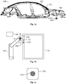
- Fig. 1a shows the body 101 of a vehicle 100, notably of a car, as an example for a general product which is assembled within an assembly line.
- an assembly line is used for assembling a sequence (e.g. thousands) of different vehicles 100 (which are at least partially identical to one another and/or which are of the same type).
- Fig. 1a highlights a place 102 within the body 101, where one or more studs are to be fixed to the body 101 within the assembly line.
- Fig. 1a shows a vehicle coordinate system 104 which is positioned at a vehicle reference point 103.
- the vehicle reference point 103 may be the center of the front axis of the vehicle 100.
- the vehicle coordinate system 104 may comprise an x-axis (pointing from the front to the back of the vehicle 100), a y-axis (pointing from the left to the right of the vehicle 100) and a z-axis (pointing from the bottom to the top of the vehicle 100).
- Fig 1b shows an excerpt of an assembly line.
- Fig. 1b illustrates a rotating head system 110 which comprises a head 111 that may be rotated around a rotation point 121.
- the head 111 may be configured to fix, notably to weld, one or more studs 131 onto the body 101 of the vehicle 100.
- the pose of the head 111 may be indicated within a head coordinate system 124 having its origin at the rotation point 121.
- the head 111 of the rotating head system 110 may exhibit a reference point 112 at the front of the head 111 (as shown in Fig. 1c ).
- the reference point 112 may e.g. correspond to a device for grabbing a stud 131.
- the head 111 and/or the rotating point 121 should exhibit a target pose (i.e. a target position and/or a target orientation) relative to the vehicle coordinate system 104, notably when fixing the stud 131 onto the body 101 of the vehicle 100.
- the method described in the present document may be directed at determining the pose of the head 111 or the rotation point 121 of the rotating head system 100 relative to the vehicle coordinate system 104.
- Fig. 2a illustrates a scheme and/or a system for determining the actual pose of the head 111 of the rotating head system 110.
- the offset between the actual pose and the target pose may be used to operate the rotating head system 100, in order to enable a precise and a collision-free operation of the head 111,
- Fig. 2a shows the head 111 and a plurality of sensors 201, 202, 203, 204, notably a plurality of cameras, which are placed at different angles 231, 232, 233, 234 and/or orientations 211, 212, 213, 214 around the head 111 (i.e. around the rotation point 121).
- Example angles 231, 232, 233, 234 and/or orientations 211, 212, 213, 214 are 90°, 135°, 180°, and 225° (possibly offset by ⁇ 90°).
- the head 111 may be turned sequentially to the different orientations 211, 212, 213, 214.
- the respective sensor 201, 202, 203, 204 may then capture sensor data (notably image data) regarding the reference point 112 of the head 111. Furthermore, the control unit 150 may be configured to determine, based on the respective sensor data, a deviation of the actual position of the reference point 112 from a target position of the reference point 112.
- Fig. 2b shows an example image captured by a sensor 201, 202, 203, 204.
- the image shows the reference point 112 located at an actual position 212.
- Fig. 2b indicates the target position 211 for the reference point 112.
- the deviation between the actual position 212 and the target position 211 is given by a first deviation component 221 along a first axis and a second deviation component 222 along a second axis of the respective image.
- K different (multi-dimensional) deviations between the actual position 212 and the target position 211 can be determined.
- the K different deviations may be combined into a deviation vector [ DEV ].
- the deviation vector [ DEV ] may be a 2 K x 1 vector which comprises the deviation components 221, 222 for the K different orientations 211, 212, 213, 214.
- the deviation vector [ DEV ] may be used to determine the actual pose of the head 111 and/or the rotation point 121 of the rotating head system 110 within the vehicle coordinate system 104. Notably an offset of the actual pose from a target pose may be determined. The actual pose or the offset can be taken into account during operation of the rotating head system 110, in order to enable the rotating head system 110 to operate in a precise and collision-free manner.
- ⁇ denotes the cross-product operation
- the vector [ x , y , z ] T denotes the position of a camera 201, 202, 203, 204.
- a camera 201, 202, 203, 204 is typically only configured to capture image data on a two-dimensional (2D) plane.
- the orientation of the 2D plane of a camera 201, 202, 203, 204 within a 3D coordinate system can be described by the orientation of the two axis which span the 2D plane.
- the orientation of the first axis may be given by a first orientation vector V 1 x V 1 y V 1 z and the orientation of the second axis may be given by a second orientation vector V 2 x V 2 y V 2 z .
- a Jacobian matrix J may be determined by regrouping the Jacobian components or row vectors of the K cameras 201, 202, 203, 204 into a 6 x 2 K matrix.
- the Jacobian matrix J may be inversed using a known inversion method to provide a (pseudo) inverse matrix J -1 .
- the (pseudo) inverse matrix J -1 for a particular setup of cameras 201, 202, 203, 204 may be determined in advance.
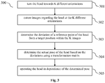
- Fig. 3 shows a flow chart of an example method 300 for operating a rotating head system 110, wherein the rotating head system 110 comprises a head 111 which is configured to be rotated around a rotation point 121.
- the head 111 may be used for welding studs 131 onto the bodies 101 of products 100 (notably vehicles) which are manufactured on an assembly line.
- the method 300 may comprise a calibration phase, during which an offset of the actual pose of the rotation point 121 or the head 111 from a target pose is determined. The offset may be used subsequently during operation of the rotating head system 110, in order to allow for a precise and collision-free operation of the rotating head system 110.
- the head 111 may comprise one or more tools at the front face of the head 111 (e.g. a welding tool and/or a grabbing device).
- the head 111 may be rotated 301 around the rotation point 121 such that the front face of the head 111 faces in a sequential manner the K different cameras 201, 202, 203, 204.
- the method 300 comprises capturing 302 K images using the K different cameras 201, 202, 203, 204, respectively.
- the K images maybe captured sequentially as the head 111 is rotated into the K different orientations 211, 212, 213, 214, such that each image is indicative of the front face of the head 111. If the head 111 is positioned correctly with respect to the product 100, the front face of the head 111, notably a reference point 112 on the front face of the head 111, should be located at a target position 211 within each one of the K images. However, an offset of the actual pose of the head 111 (or rotation point 121) from the target pose of the head 111 (or rotation point 121) typically leads to a deviation of the reference point 112 from the target position 211 in at least one of the K images.
- the method 300 further comprises determining 303 K deviations of the reference point 112 of the head 111 from the target position 211 within the K images, respectively. Hence, K deviation values or deviation vectors may be determined.
- the method 300 may comprise determining 304 an offset of the actual pose of the head 111 from the target pose based on the K deviations using a transformation matrix (notably using an estimate of an inverse of a Jacobian matrix which describes the measurement setup for measuring the K deviations).
- the offset may describe the translational and/or rotational offset of the actual pose of the head 111 from the target pose.
- the method 300 may comprise operating 305 the head 111 for manufacturing products 100, in dependence of the offset.
- a welding process which is performed by the rotating head system 110 may be performed in dependence of the offset which has been determined during calibration. By doing this, a precise and collision-free operation of the rotating head system 110 may be ensured.
Landscapes
- Engineering & Computer Science (AREA)
- Robotics (AREA)
- Mechanical Engineering (AREA)
- Image Processing (AREA)
- Image Analysis (AREA)
Abstract
Description
- The present document is directed at the control of a rotating head system, such as a stud welding device.
- Vehicles, notably cars, are typically manufactured within an assembly line using one or more rotating head systems. A rotating head system may e.g. be configured to weld one or more studs onto the body of a vehicle. An erroneous positioning of the head of the rotating head system relative to the body of the vehicle (e.g. subsequent to maintenance of the rotating head system) may lead to a collision between the rotating head system and the vehicle body and/or may lead to a wrong placement of the one or more studs on the vehicle body.
- The present document is directed at the technical problem of enabling an efficient and precise positioning of the head of a rotating head system relative to the body of a product, notably to a vehicle body, that is manufactured using the rotating head system.
- According to an aspect a method for operating a rotating head system is described. The rotating head system comprises a head which is configured to be rotated around a rotation point. The head may be used to perform a welding process during assembly of a product (notably a vehicle). In particular, the head may be configured to weld one or more studs onto the body of a product. This process may be repeated for a sequence of products within an assembly line. The method may be directed at calibrating the rotating head system (e.g. subsequent to maintenance of the rotating head system), such that the rotating head system is aware of the pose of the head of the rotating head system relative to the one or more products on the assembly line.
- The method may comprise (during a calibration phase) rotating the head (around the rotation point) into K different orientations to face K different cameras, respectively, with K > 3 (wherein K is an integer). Each camera may be configured to capture an image of the front face of the head. The front face of the head may comprise one or more tools (e.g. for welding and/or for grabbing), which may be used as a reference point of the front face of the head. In particular, the head may comprise a grabbing device for grabbing a stud, and the reference point may be located on the grabbing device.
- The K cameras may be arranged at K different angles around the rotation point of the head, wherein the K different angles may span an angular range of 45° or more, or 90° or more. By placing cameras at K different angles which span a relatively large angular range, the offset of the actual pose of the head relative to the target pose of the head may be determined in a particularly precise manner.
- The method may further comprise capturing K images using the K different cameras, respectively. The K (two-dimensional) images may be determined sequentially as the head is turned towards the K different cameras. In particular, a first image may be captured when the head is facing a first camera, a second image may be captured when the head is facing the second camera, and so on, until capturing a K th image when the head is facing the K th camera.
- The reference point of the (front face of the) head may exhibit a target position within each one of the K images, if the head (or the rotation point of the head) exhibits the target pose. The K different cameras may be positioned around the rotation point such that an offset of the actual pose of the head (or the rotation point) from the target pose leads to a deviation of the reference point of the head from the target position within at least one of the K images.
- The method may comprise determining K deviations (i.e. deviation values or deviation vectors) of the reference point of the head from the target position within the K images, respectively. The deviation may be zero, if the reference point is located at the target position.
- Furthermore, the method may comprise determining an offset of the head from the target pose based on the K deviations using a transformation matrix, wherein the transformation matrix may comprise a Jacobian matrix or an estimate of an inverse of a Jacobian matrix. As indicated above, the offset may be indicative of a translational offset and/or of a rotational offset from the target pose. Hence, the offset may be a 3- or a 6-dimensional vector.
- The offset may be provided as the outcome of the calibration phase of the rotating head system. Furthermore, the offset may be used during operation of the rotating head system. In particular, the method may comprise operating the head in dependence of the offset, wherein operating the head may comprise welding one or more studs to a product using the head of the rotating head system. By taking into account the offset during operation of the rotating head system, a precise and collision-free operation of the rotating head system may be ensured.
- The transformation matrix may be dependent on the K different orientations and/or angles of the cameras. Alternatively, or in addition, the transformation matrix may be dependent on positions of the K different cameras relative to the rotation point. As a result of this, the offset may be determined in a precise manner.
- The method may comprise determining a deviation vector indicative of the K deviations of the reference point of the head from the target position. The deviation vector may comprise vector elements for each of the K images. Furthermore, the method may comprise multiplying the deviation vector with the transformation matrix to determine an offset vector, wherein the offset vector is indicative of the translational offset and/or the rotational offset of the actual pose of the head from the target pose. As a result of this, the offset may be determined in an efficient and precise manner.
- The deviation of the reference point of the head from the target position within a particular image of the K images may comprise a first deviation component along a first axis (e.g. the x-axis) of the particular image and a second deviation component along a second axis (e.g. the y-axis) of the particular image. The deviation vector may comprise as vector elements the first deviation components and the second deviation components for each of the K deviations, i.e. for each one of the K images, thereby allowing the offset to be determined in a precise manner.
- As indicated above, the transformation matrix may be the inverse or an estimate of the inverse of a Jacobian matrix. The Jacobian matrix may comprise a row vector for each vector element of the deviation vector (i.e. for each deviation component). The row vector of the Jacobian matrix for the first deviation component along the first axis of the particular image may comprise the following vector elements




- According to a further aspect, a control unit for controlling a rotating head system which is configured to attach a part onto a body of a product using a head which is configured to be rotated around a rotation point is described. The control unit may be configured to rotate the head into K different orientations to face K different cameras, respectively, with K > 3, and to capture K images (regarding the front face of the head) using the K different cameras, respectively. Furthermore, the control unit is configured to determine K deviations of a reference point of the head from a target position within the K images, respectively, and to determine an offset of the head from a target pose based on the K deviations using a transformation matrix. In addition, the control unit may be configured to operate the head for attaching a part (notably a stud) onto a body of a product in dependence of the offset.
- According to a further aspect, a rotating head system comprising the control unit which is described in the present document is described.
- It should be noted that the methods and systems including its preferred embodiments as outlined in the present document may be used stand-alone or in combination with the other methods and systems disclosed in this document. In addition, the features outlined in the context of a system are also applicable to a corresponding method. Furthermore, all aspects of the methods and systems outlined in the present document may be arbitrarily combined. In particular, the features of the claims may be combined with one another in an arbitrary manner.
- The invention is explained below in an exemplary manner with reference to the accompanying drawings, wherein
-
Figure 1a shows an example body of a vehicle; -
Figure 1b illustrates an example welding process using a rotating head system; -
Figure 1c shows an example reference point on the front face of the head of a rotating head system; -
Figure 2a shows an example arrangement of sensors (notably of cameras) around the head of a rotating head system; -
Figure 2b illustrates the offset of the reference point of the head of a rotating head system from a target position; and -
Figure 3 shows a flow chart of an example method for operating a rotating head system. - As outlined in the introductory section, the present document is directed at operating a rotating head system in a precise and reliable manner within a manufacturing process. In this context,
Fig. 1a shows thebody 101 of avehicle 100, notably of a car, as an example for a general product which is assembled within an assembly line. Typically, an assembly line is used for assembling a sequence (e.g. thousands) of different vehicles 100 (which are at least partially identical to one another and/or which are of the same type). - Furthermore,
Fig. 1a highlights aplace 102 within thebody 101, where one or more studs are to be fixed to thebody 101 within the assembly line. In addition,Fig. 1a shows a vehicle coordinatesystem 104 which is positioned at avehicle reference point 103. Thevehicle reference point 103 may be the center of the front axis of thevehicle 100. The vehicle coordinatesystem 104 may comprise an x-axis (pointing from the front to the back of the vehicle 100), a y-axis (pointing from the left to the right of the vehicle 100) and a z-axis (pointing from the bottom to the top of the vehicle 100). -
Fig 1b shows an excerpt of an assembly line. In particular,Fig. 1b illustrates arotating head system 110 which comprises ahead 111 that may be rotated around arotation point 121. Thehead 111 may be configured to fix, notably to weld, one ormore studs 131 onto thebody 101 of thevehicle 100. The pose of thehead 111 may be indicated within a head coordinatesystem 124 having its origin at therotation point 121. - The
head 111 of therotating head system 110 may exhibit areference point 112 at the front of the head 111 (as shown inFig. 1c ). Thereference point 112 may e.g. correspond to a device for grabbing astud 131. - In order to enable an exact placement of a
stud 131 onto thebody 101 and/or in order to avoid a collision between thehead 111 and thebody 101 during operation of therotating head system 110, thehead 111 and/or therotating point 121 should exhibit a target pose (i.e. a target position and/or a target orientation) relative to the vehicle coordinatesystem 104, notably when fixing thestud 131 onto thebody 101 of thevehicle 100. The method described in the present document may be directed at determining the pose of thehead 111 or therotation point 121 of therotating head system 100 relative to the vehicle coordinatesystem 104. -
Fig. 2a illustrates a scheme and/or a system for determining the actual pose of thehead 111 of therotating head system 110. The offset between the actual pose and the target pose may be used to operate therotating head system 100, in order to enable a precise and a collision-free operation of thehead 111, -
Fig. 2a shows thehead 111 and a plurality ofsensors different angles orientations orientations head 111 may be turned sequentially to thedifferent orientations respective sensor reference point 112 of thehead 111. Furthermore, thecontrol unit 150 may be configured to determine, based on the respective sensor data, a deviation of the actual position of thereference point 112 from a target position of thereference point 112. -
Fig. 2b shows an example image captured by asensor reference point 112 located at anactual position 212. Furthermore,Fig. 2b indicates thetarget position 211 for thereference point 112. The deviation between theactual position 212 and thetarget position 211 is given by afirst deviation component 221 along a first axis and asecond deviation component 222 along a second axis of the respective image. - When using K measurements for K
different orientations actual position 212 and thetarget position 211 can be determined. The K different deviations may be combined into a deviation vector [DEV]. The deviation vector [DEV] may be a 2K x 1 vector which comprises thedeviation components different orientations - Using a Jacobian matrix J, the deviation vector [DEV] may be used to determine the actual pose of the
head 111 and/or therotation point 121 of therotating head system 110 within the vehicle coordinatesystem 104. Notably an offset of the actual pose from a target pose may be determined. The actual pose or the offset can be taken into account during operation of therotating head system 110, in order to enable therotating head system 110 to operate in a precise and collision-free manner. - It can be shown that for relatively small translations, the (translational) offset of the pose can be described as


- In a similar manner, the (rotational) offset of the pose for a relatively small rotation may be given by

camera - A
camera camera 

- For each camera 201, 202, 203, 204, a first Jacobian component or row vector (i.e. a 1 x 6 vector) for the first axis of the 2D plane of the camera 201, 202, 203, 204, 204 can be calculated as


- Using the above mentioned formula, a Jacobian matrix J may be determined by regrouping the Jacobian components or row vectors of the
K cameras head 111 or therotation point 121 may then be determined as
- The (pseudo) inverse matrix J -1 for a particular setup of
cameras -
Fig. 3 shows a flow chart of anexample method 300 for operating arotating head system 110, wherein therotating head system 110 comprises ahead 111 which is configured to be rotated around arotation point 121. Thehead 111 may be used for weldingstuds 131 onto thebodies 101 of products 100 (notably vehicles) which are manufactured on an assembly line. Themethod 300 may comprise a calibration phase, during which an offset of the actual pose of therotation point 121 or thehead 111 from a target pose is determined. The offset may be used subsequently during operation of therotating head system 110, in order to allow for a precise and collision-free operation of therotating head system 110. - The
method 300 comprises rotating 301 thehead 111 into Kdifferent orientations different cameras head 111 may comprise one or more tools at the front face of the head 111 (e.g. a welding tool and/or a grabbing device). Thehead 111 may be rotated 301 around therotation point 121 such that the front face of thehead 111 faces in a sequential manner the Kdifferent cameras - Furthermore, the
method 300 comprises capturing 302 K images using the Kdifferent cameras head 111 is rotated into the Kdifferent orientations head 111. If thehead 111 is positioned correctly with respect to theproduct 100, the front face of thehead 111, notably areference point 112 on the front face of thehead 111, should be located at atarget position 211 within each one of the K images. However, an offset of the actual pose of the head 111 (or rotation point 121) from the target pose of the head 111 (or rotation point 121) typically leads to a deviation of thereference point 112 from thetarget position 211 in at least one of the K images. - The
method 300 further comprises determining 303 K deviations of thereference point 112 of thehead 111 from thetarget position 211 within the K images, respectively. Hence, K deviation values or deviation vectors may be determined. Themethod 300 may comprise determining 304 an offset of the actual pose of thehead 111 from the target pose based on the K deviations using a transformation matrix (notably using an estimate of an inverse of a Jacobian matrix which describes the measurement setup for measuring the K deviations). The offset may describe the translational and/or rotational offset of the actual pose of thehead 111 from the target pose. - In addition, the
method 300 may comprise operating 305 thehead 111 formanufacturing products 100, in dependence of the offset. In particular, a welding process which is performed by therotating head system 110 may be performed in dependence of the offset which has been determined during calibration. By doing this, a precise and collision-free operation of therotating head system 110 may be ensured. - It should be noted that the description and drawings merely illustrate the principles of the proposed methods and systems. Those skilled in the art will be able to implement various arrangements that, although not explicitly described or shown herein, embody the principles of the invention and are included within its spirit and scope. Furthermore, all examples and embodiment outlined in the present document are principally intended expressly to be only for explanatory purposes to help the reader in understanding the principles of the proposed methods and systems. Furthermore, all statements herein providing principles, aspects, and embodiments of the invention, as well as specific examples thereof, are intended to encompass equivalents thereof.
Claims (10)
- A method (300) for operating a rotating head system (110), wherein the rotating head system (110) comprises a head (111) which is configured to be rotated around a rotation point (121); wherein the method (300) comprises,- rotating (301) the head (111) into K different orientations (211, 212, 213, 214) to face K different cameras (201, 202, 203, 204), respectively, with K > 3;- capturing (302) K images using the K different cameras (201, 202, 203, 204), respectively;- determining (303) K deviations of a reference point (112) of the head (111) from a target position (211) within the K images, respectively;- determining (304) an offset of an actual pose of the head (111) from a target pose based on the K deviations using a transformation matrix; and- operating (305) the head (111) in dependence of the offset.
- The method (300) of claim 1, wherein- the transformation matrix comprises a Jacobian matrix or an estimate of an inverse of a Jacobian matrix; and/or- the transformation matrix is dependent on the K different orientations (211, 212, 213, 214); and/or- the transformation matrix is dependent on positions of the K different cameras (201, 202, 203, 204) relative to the rotation point (121).
- The method (300) of any previous claim, wherein the method (300) comprises- determining a deviation vector indicative of the K deviations of the reference point (112) of the head (111) from the target position (211); and- multiplying the deviation vector with the transformation matrix to determine an offset vector; wherein the offset vector is indicative of a translational offset and/or a rotational offset of an actual pose of the head (111) from the target pose.
- The method (300) of claim 3, wherein- the deviation of the reference point (112) of the head (111) from the target position (211) within a particular image of the K images comprises a first deviation component (221) along a first axis of the particular image and a second deviation component (222) along a second axis of the particular image; and- the deviation vector comprises as vector elements the first deviation components (221) and the second deviation components (222) for the K deviations.
- The method (300) of claim 4, wherein- the transformation matrix is an inverse of a Jacobian matrix; and- the Jacobian matrix comprises a row vector for each vector element of the deviation vector.
- The method (300) of claim 5, wherein- the row vector of the Jacobian matrix for the first deviation component (221) along the first axis of the particular image comprises the vector elements

 -
- -
- - ° is the projection operator.
 - The method (300) of any previous claim, wherein operating (305) the head (111) comprises welding one or more studs (131) to a product (100) using the head (111) of the rotating head system (110).
- The method (300) of any previous claim, wherein- the head (111) comprises a grabbing device for grabbing a stud (131); and- the reference point (112) is located on the grabbing device.
- The method (300) of any previous claim, wherein- the K cameras (201, 202, 203, 204) are arranged at K different angles (231, 232, 233, 234) around the rotation point (121); and- the K different angles span an angular range of 45° or more.
- A control unit (150) for controlling a rotating head system (110) which is configured to attach a part (131) onto a body (101) of a product (100) using a head (111) which is configured to be rotated around a rotation point (121); wherein the control unit (150) is configured to- rotate the head (111) into K different orientations (211, 212, 213, 214) to face K different cameras (201, 202, 203, 204), respectively, with K > 3;- capture K images using the K different cameras (201, 202, 203, 204), respectively;- determine K deviations of a reference point (112) of the head (111) from a target position (211) within the K images, respectively;- determine an offset of an actual pose of the head (111) from a target pose based on the K deviations using a transformation matrix; and- operate the head (111) for attaching a part (131) onto a body (101) of a product (100) in dependence of the offset.
Priority Applications (1)
| Application Number | Priority Date | Filing Date | Title |
|---|---|---|---|
| EP19196855.1A EP3792012B1 (en) | 2019-09-12 | 2019-09-12 | Method and control unit for operating a rotating head system with multiple cameras |
Applications Claiming Priority (1)
| Application Number | Priority Date | Filing Date | Title |
|---|---|---|---|
| EP19196855.1A EP3792012B1 (en) | 2019-09-12 | 2019-09-12 | Method and control unit for operating a rotating head system with multiple cameras |
Publications (2)
| Publication Number | Publication Date |
|---|---|
| EP3792012A1 true EP3792012A1 (en) | 2021-03-17 |
| EP3792012B1 EP3792012B1 (en) | 2023-12-27 |
Family
ID=67997334
Family Applications (1)
| Application Number | Title | Priority Date | Filing Date |
|---|---|---|---|
| EP19196855.1A Active EP3792012B1 (en) | 2019-09-12 | 2019-09-12 | Method and control unit for operating a rotating head system with multiple cameras |
Country Status (1)
| Country | Link |
|---|---|
| EP (1) | EP3792012B1 (en) |
Cited By (1)
| Publication number | Priority date | Publication date | Assignee | Title |
|---|---|---|---|---|
| EP4079463A1 (en) * | 2021-04-20 | 2022-10-26 | Bayerische Motoren Werke Aktiengesellschaft | Method and control unit for calibrating a rotating head system |
Citations (4)
| Publication number | Priority date | Publication date | Assignee | Title |
|---|---|---|---|---|
| EP1345099A2 (en) * | 2002-03-04 | 2003-09-17 | TECMEDIC GmbH | Method for determining the spatial position of an object and a workpiece for automatically mounting the workpiece on the object |
| US20050273202A1 (en) * | 2004-06-02 | 2005-12-08 | Rainer Bischoff | Method and device for improving the positioning accuracy of a manipulator |
| US20190047151A1 (en) * | 2015-09-29 | 2019-02-14 | Koninklijke Philips N.V. | Automatic robotic arm calibration to camera system using a laser |
| US20190084160A1 (en) * | 2010-05-14 | 2019-03-21 | Cognex Corporation | System and method for robust calibration between a machine vision system and a robot |
-
2019
- 2019-09-12 EP EP19196855.1A patent/EP3792012B1/en active Active
Patent Citations (4)
| Publication number | Priority date | Publication date | Assignee | Title |
|---|---|---|---|---|
| EP1345099A2 (en) * | 2002-03-04 | 2003-09-17 | TECMEDIC GmbH | Method for determining the spatial position of an object and a workpiece for automatically mounting the workpiece on the object |
| US20050273202A1 (en) * | 2004-06-02 | 2005-12-08 | Rainer Bischoff | Method and device for improving the positioning accuracy of a manipulator |
| US20190084160A1 (en) * | 2010-05-14 | 2019-03-21 | Cognex Corporation | System and method for robust calibration between a machine vision system and a robot |
| US20190047151A1 (en) * | 2015-09-29 | 2019-02-14 | Koninklijke Philips N.V. | Automatic robotic arm calibration to camera system using a laser |
Cited By (1)
| Publication number | Priority date | Publication date | Assignee | Title |
|---|---|---|---|---|
| EP4079463A1 (en) * | 2021-04-20 | 2022-10-26 | Bayerische Motoren Werke Aktiengesellschaft | Method and control unit for calibrating a rotating head system |
Also Published As
| Publication number | Publication date |
|---|---|
| EP3792012B1 (en) | 2023-12-27 |
Similar Documents
| Publication | Publication Date | Title |
|---|---|---|
| US10618166B2 (en) | Teaching position correction device and teaching position correction method | |
| EP1607194B1 (en) | Robot system comprising a plurality of robots provided with means for calibrating their relative position | |
| JP3733364B2 (en) | Teaching position correction method | |
| CN102909728B (en) | The vision correction methods of robot tooling center points | |
| EP3366433A1 (en) | Method of controlling robot, method of teaching robot, and robot system | |
| US9857786B2 (en) | System and method for aligning a coordinated movement machine reference frame with a measurement system reference frame | |
| US8918210B2 (en) | Method of detecting an inter-axis offset of 6-axis robot | |
| US7532949B2 (en) | Measuring system | |
| US9517560B2 (en) | Robot system and calibration method of the robot system | |
| JP3665353B2 (en) | 3D position correction amount acquisition method of robot teaching position data and robot system | |
| US20190015989A1 (en) | Robot Control Device, Robot, Robot System, And Calibration Method Of Camera | |
| US20190015988A1 (en) | Robot control device, robot, robot system, and calibration method of camera for robot | |
| US9956686B2 (en) | Deflection measurement system for measuring deflection of articulated robot | |
| US12005591B2 (en) | Ultrasonic testing system of dual robot arms and method thereof | |
| US11090810B2 (en) | Robot system | |
| US11524407B2 (en) | Robot system and operating method thereof | |
| JPH08132373A (en) | Coordinate system coupling method in robot-sensor system | |
| EP3792012B1 (en) | Method and control unit for operating a rotating head system with multiple cameras | |
| US11738462B2 (en) | Coordinate calibration method of manipulator | |
| EP3620270B1 (en) | Method and control unit for controlling an assembly robot | |
| KR101048467B1 (en) | Position measuring method of conveyor-based body | |
| JP7011805B2 (en) | Robot control device and robot control method for setting robot control points | |
| EP4079463A1 (en) | Method and control unit for calibrating a rotating head system | |
| Cheng et al. | Efficient hand eye calibration method for a Delta robot pick-and-place system | |
| US20230031819A1 (en) | Positioning method and positioning device |
Legal Events
| Date | Code | Title | Description |
|---|---|---|---|
| PUAI | Public reference made under article 153(3) epc to a published international application that has entered the european phase |
Free format text: ORIGINAL CODE: 0009012 |
|
| STAA | Information on the status of an ep patent application or granted ep patent |
Free format text: STATUS: THE APPLICATION HAS BEEN PUBLISHED |
|
| AK | Designated contracting states |
Kind code of ref document: A1 Designated state(s): AL AT BE BG CH CY CZ DE DK EE ES FI FR GB GR HR HU IE IS IT LI LT LU LV MC MK MT NL NO PL PT RO RS SE SI SK SM TR |
|
| AX | Request for extension of the european patent |
Extension state: BA ME |
|
| STAA | Information on the status of an ep patent application or granted ep patent |
Free format text: STATUS: REQUEST FOR EXAMINATION WAS MADE |
|
| 17P | Request for examination filed |
Effective date: 20210331 |
|
| RBV | Designated contracting states (corrected) |
Designated state(s): AL AT BE BG CH CY CZ DE DK EE ES FI FR GB GR HR HU IE IS IT LI LT LU LV MC MK MT NL NO PL PT RO RS SE SI SK SM TR |
|
| STAA | Information on the status of an ep patent application or granted ep patent |
Free format text: STATUS: EXAMINATION IS IN PROGRESS |
|
| 17Q | First examination report despatched |
Effective date: 20220419 |
|
| P01 | Opt-out of the competence of the unified patent court (upc) registered |
Effective date: 20230503 |
|
| GRAP | Despatch of communication of intention to grant a patent |
Free format text: ORIGINAL CODE: EPIDOSNIGR1 |
|
| STAA | Information on the status of an ep patent application or granted ep patent |
Free format text: STATUS: GRANT OF PATENT IS INTENDED |
|
| INTG | Intention to grant announced |
Effective date: 20230914 |
|
| GRAS | Grant fee paid |
Free format text: ORIGINAL CODE: EPIDOSNIGR3 |
|
| GRAA | (expected) grant |
Free format text: ORIGINAL CODE: 0009210 |
|
| STAA | Information on the status of an ep patent application or granted ep patent |
Free format text: STATUS: THE PATENT HAS BEEN GRANTED |
|
| AK | Designated contracting states |
Kind code of ref document: B1 Designated state(s): AL AT BE BG CH CY CZ DE DK EE ES FI FR GB GR HR HU IE IS IT LI LT LU LV MC MK MT NL NO PL PT RO RS SE SI SK SM TR |
|
| REG | Reference to a national code |
Ref country code: GB Ref legal event code: FG4D |
|
| REG | Reference to a national code |
Ref country code: CH Ref legal event code: EP |
|
| REG | Reference to a national code |
Ref country code: DE Ref legal event code: R096 Ref document number: 602019043896 Country of ref document: DE |
|
| REG | Reference to a national code |
Ref country code: IE Ref legal event code: FG4D |
|
| PG25 | Lapsed in a contracting state [announced via postgrant information from national office to epo] |
Ref country code: GR Free format text: LAPSE BECAUSE OF FAILURE TO SUBMIT A TRANSLATION OF THE DESCRIPTION OR TO PAY THE FEE WITHIN THE PRESCRIBED TIME-LIMIT Effective date: 20240328 |
|
| REG | Reference to a national code |
Ref country code: LT Ref legal event code: MG9D |
|
| PG25 | Lapsed in a contracting state [announced via postgrant information from national office to epo] |
Ref country code: LT Free format text: LAPSE BECAUSE OF FAILURE TO SUBMIT A TRANSLATION OF THE DESCRIPTION OR TO PAY THE FEE WITHIN THE PRESCRIBED TIME-LIMIT Effective date: 20231227 |
|
| PG25 | Lapsed in a contracting state [announced via postgrant information from national office to epo] |
Ref country code: ES Free format text: LAPSE BECAUSE OF FAILURE TO SUBMIT A TRANSLATION OF THE DESCRIPTION OR TO PAY THE FEE WITHIN THE PRESCRIBED TIME-LIMIT Effective date: 20231227 |
|
| PG25 | Lapsed in a contracting state [announced via postgrant information from national office to epo] |
Ref country code: LT Free format text: LAPSE BECAUSE OF FAILURE TO SUBMIT A TRANSLATION OF THE DESCRIPTION OR TO PAY THE FEE WITHIN THE PRESCRIBED TIME-LIMIT Effective date: 20231227 Ref country code: GR Free format text: LAPSE BECAUSE OF FAILURE TO SUBMIT A TRANSLATION OF THE DESCRIPTION OR TO PAY THE FEE WITHIN THE PRESCRIBED TIME-LIMIT Effective date: 20240328 Ref country code: FI Free format text: LAPSE BECAUSE OF FAILURE TO SUBMIT A TRANSLATION OF THE DESCRIPTION OR TO PAY THE FEE WITHIN THE PRESCRIBED TIME-LIMIT Effective date: 20231227 Ref country code: ES Free format text: LAPSE BECAUSE OF FAILURE TO SUBMIT A TRANSLATION OF THE DESCRIPTION OR TO PAY THE FEE WITHIN THE PRESCRIBED TIME-LIMIT Effective date: 20231227 Ref country code: BG Free format text: LAPSE BECAUSE OF FAILURE TO SUBMIT A TRANSLATION OF THE DESCRIPTION OR TO PAY THE FEE WITHIN THE PRESCRIBED TIME-LIMIT Effective date: 20240327 |
|
| REG | Reference to a national code |
Ref country code: NL Ref legal event code: MP Effective date: 20231227 |
|
| REG | Reference to a national code |
Ref country code: AT Ref legal event code: MK05 Ref document number: 1644102 Country of ref document: AT Kind code of ref document: T Effective date: 20231227 |
|
| PG25 | Lapsed in a contracting state [announced via postgrant information from national office to epo] |
Ref country code: NL Free format text: LAPSE BECAUSE OF FAILURE TO SUBMIT A TRANSLATION OF THE DESCRIPTION OR TO PAY THE FEE WITHIN THE PRESCRIBED TIME-LIMIT Effective date: 20231227 |
|
| PG25 | Lapsed in a contracting state [announced via postgrant information from national office to epo] |
Ref country code: SE Free format text: LAPSE BECAUSE OF FAILURE TO SUBMIT A TRANSLATION OF THE DESCRIPTION OR TO PAY THE FEE WITHIN THE PRESCRIBED TIME-LIMIT Effective date: 20231227 Ref country code: RS Free format text: LAPSE BECAUSE OF FAILURE TO SUBMIT A TRANSLATION OF THE DESCRIPTION OR TO PAY THE FEE WITHIN THE PRESCRIBED TIME-LIMIT Effective date: 20231227 Ref country code: NO Free format text: LAPSE BECAUSE OF FAILURE TO SUBMIT A TRANSLATION OF THE DESCRIPTION OR TO PAY THE FEE WITHIN THE PRESCRIBED TIME-LIMIT Effective date: 20240327 Ref country code: NL Free format text: LAPSE BECAUSE OF FAILURE TO SUBMIT A TRANSLATION OF THE DESCRIPTION OR TO PAY THE FEE WITHIN THE PRESCRIBED TIME-LIMIT Effective date: 20231227 Ref country code: LV Free format text: LAPSE BECAUSE OF FAILURE TO SUBMIT A TRANSLATION OF THE DESCRIPTION OR TO PAY THE FEE WITHIN THE PRESCRIBED TIME-LIMIT Effective date: 20231227 Ref country code: HR Free format text: LAPSE BECAUSE OF FAILURE TO SUBMIT A TRANSLATION OF THE DESCRIPTION OR TO PAY THE FEE WITHIN THE PRESCRIBED TIME-LIMIT Effective date: 20231227 |
|
| PG25 | Lapsed in a contracting state [announced via postgrant information from national office to epo] |
Ref country code: IS Free format text: LAPSE BECAUSE OF FAILURE TO SUBMIT A TRANSLATION OF THE DESCRIPTION OR TO PAY THE FEE WITHIN THE PRESCRIBED TIME-LIMIT Effective date: 20240427 |
|
| PG25 | Lapsed in a contracting state [announced via postgrant information from national office to epo] |
Ref country code: CZ Free format text: LAPSE BECAUSE OF FAILURE TO SUBMIT A TRANSLATION OF THE DESCRIPTION OR TO PAY THE FEE WITHIN THE PRESCRIBED TIME-LIMIT Effective date: 20231227 Ref country code: AT Free format text: LAPSE BECAUSE OF FAILURE TO SUBMIT A TRANSLATION OF THE DESCRIPTION OR TO PAY THE FEE WITHIN THE PRESCRIBED TIME-LIMIT Effective date: 20231227 |
|
| PG25 | Lapsed in a contracting state [announced via postgrant information from national office to epo] |
Ref country code: SK Free format text: LAPSE BECAUSE OF FAILURE TO SUBMIT A TRANSLATION OF THE DESCRIPTION OR TO PAY THE FEE WITHIN THE PRESCRIBED TIME-LIMIT Effective date: 20231227 |
|
| PG25 | Lapsed in a contracting state [announced via postgrant information from national office to epo] |
Ref country code: SM Free format text: LAPSE BECAUSE OF FAILURE TO SUBMIT A TRANSLATION OF THE DESCRIPTION OR TO PAY THE FEE WITHIN THE PRESCRIBED TIME-LIMIT Effective date: 20231227 Ref country code: SK Free format text: LAPSE BECAUSE OF FAILURE TO SUBMIT A TRANSLATION OF THE DESCRIPTION OR TO PAY THE FEE WITHIN THE PRESCRIBED TIME-LIMIT Effective date: 20231227 Ref country code: RO Free format text: LAPSE BECAUSE OF FAILURE TO SUBMIT A TRANSLATION OF THE DESCRIPTION OR TO PAY THE FEE WITHIN THE PRESCRIBED TIME-LIMIT Effective date: 20231227 Ref country code: IT Free format text: LAPSE BECAUSE OF FAILURE TO SUBMIT A TRANSLATION OF THE DESCRIPTION OR TO PAY THE FEE WITHIN THE PRESCRIBED TIME-LIMIT Effective date: 20231227 Ref country code: IS Free format text: LAPSE BECAUSE OF FAILURE TO SUBMIT A TRANSLATION OF THE DESCRIPTION OR TO PAY THE FEE WITHIN THE PRESCRIBED TIME-LIMIT Effective date: 20240427 Ref country code: EE Free format text: LAPSE BECAUSE OF FAILURE TO SUBMIT A TRANSLATION OF THE DESCRIPTION OR TO PAY THE FEE WITHIN THE PRESCRIBED TIME-LIMIT Effective date: 20231227 Ref country code: CZ Free format text: LAPSE BECAUSE OF FAILURE TO SUBMIT A TRANSLATION OF THE DESCRIPTION OR TO PAY THE FEE WITHIN THE PRESCRIBED TIME-LIMIT Effective date: 20231227 Ref country code: AT Free format text: LAPSE BECAUSE OF FAILURE TO SUBMIT A TRANSLATION OF THE DESCRIPTION OR TO PAY THE FEE WITHIN THE PRESCRIBED TIME-LIMIT Effective date: 20231227 |
|
| PG25 | Lapsed in a contracting state [announced via postgrant information from national office to epo] |
Ref country code: PL Free format text: LAPSE BECAUSE OF FAILURE TO SUBMIT A TRANSLATION OF THE DESCRIPTION OR TO PAY THE FEE WITHIN THE PRESCRIBED TIME-LIMIT Effective date: 20231227 Ref country code: PT Free format text: LAPSE BECAUSE OF FAILURE TO SUBMIT A TRANSLATION OF THE DESCRIPTION OR TO PAY THE FEE WITHIN THE PRESCRIBED TIME-LIMIT Effective date: 20240429 |
|
| PG25 | Lapsed in a contracting state [announced via postgrant information from national office to epo] |
Ref country code: PT Free format text: LAPSE BECAUSE OF FAILURE TO SUBMIT A TRANSLATION OF THE DESCRIPTION OR TO PAY THE FEE WITHIN THE PRESCRIBED TIME-LIMIT Effective date: 20240429 Ref country code: PL Free format text: LAPSE BECAUSE OF FAILURE TO SUBMIT A TRANSLATION OF THE DESCRIPTION OR TO PAY THE FEE WITHIN THE PRESCRIBED TIME-LIMIT Effective date: 20231227 |
|
| REG | Reference to a national code |
Ref country code: DE Ref legal event code: R097 Ref document number: 602019043896 Country of ref document: DE |
|
| PG25 | Lapsed in a contracting state [announced via postgrant information from national office to epo] |
Ref country code: DK Free format text: LAPSE BECAUSE OF FAILURE TO SUBMIT A TRANSLATION OF THE DESCRIPTION OR TO PAY THE FEE WITHIN THE PRESCRIBED TIME-LIMIT Effective date: 20231227 |
|
| PG25 | Lapsed in a contracting state [announced via postgrant information from national office to epo] |
Ref country code: DK Free format text: LAPSE BECAUSE OF FAILURE TO SUBMIT A TRANSLATION OF THE DESCRIPTION OR TO PAY THE FEE WITHIN THE PRESCRIBED TIME-LIMIT Effective date: 20231227 |
|
| PLBE | No opposition filed within time limit |
Free format text: ORIGINAL CODE: 0009261 |
|
| STAA | Information on the status of an ep patent application or granted ep patent |
Free format text: STATUS: NO OPPOSITION FILED WITHIN TIME LIMIT |
|
| 26N | No opposition filed |
Effective date: 20240930 |
|
| PG25 | Lapsed in a contracting state [announced via postgrant information from national office to epo] |
Ref country code: SI Free format text: LAPSE BECAUSE OF FAILURE TO SUBMIT A TRANSLATION OF THE DESCRIPTION OR TO PAY THE FEE WITHIN THE PRESCRIBED TIME-LIMIT Effective date: 20231227 Ref country code: MC Free format text: LAPSE BECAUSE OF FAILURE TO SUBMIT A TRANSLATION OF THE DESCRIPTION OR TO PAY THE FEE WITHIN THE PRESCRIBED TIME-LIMIT Effective date: 20231227 |
|
| REG | Reference to a national code |
Ref country code: CH Ref legal event code: PL |
|
| PG25 | Lapsed in a contracting state [announced via postgrant information from national office to epo] |
Ref country code: LU Free format text: LAPSE BECAUSE OF NON-PAYMENT OF DUE FEES Effective date: 20240912 |
|
| REG | Reference to a national code |
Ref country code: BE Ref legal event code: MM Effective date: 20240930 |
|
| PG25 | Lapsed in a contracting state [announced via postgrant information from national office to epo] |
Ref country code: BE Free format text: LAPSE BECAUSE OF NON-PAYMENT OF DUE FEES Effective date: 20240930 |
|
| PG25 | Lapsed in a contracting state [announced via postgrant information from national office to epo] |
Ref country code: CH Free format text: LAPSE BECAUSE OF NON-PAYMENT OF DUE FEES Effective date: 20240930 |
|
| PG25 | Lapsed in a contracting state [announced via postgrant information from national office to epo] |
Ref country code: IE Free format text: LAPSE BECAUSE OF NON-PAYMENT OF DUE FEES Effective date: 20240912 |
|
| PGFP | Annual fee paid to national office [announced via postgrant information from national office to epo] |
Ref country code: DE Payment date: 20250909 Year of fee payment: 7 |
|
| PGFP | Annual fee paid to national office [announced via postgrant information from national office to epo] |
Ref country code: GB Payment date: 20250923 Year of fee payment: 7 |
|
| PGFP | Annual fee paid to national office [announced via postgrant information from national office to epo] |
Ref country code: FR Payment date: 20250924 Year of fee payment: 7 |
|
| PG25 | Lapsed in a contracting state [announced via postgrant information from national office to epo] |
Ref country code: CY Free format text: LAPSE BECAUSE OF FAILURE TO SUBMIT A TRANSLATION OF THE DESCRIPTION OR TO PAY THE FEE WITHIN THE PRESCRIBED TIME-LIMIT; INVALID AB INITIO Effective date: 20190912 |
|
| PG25 | Lapsed in a contracting state [announced via postgrant information from national office to epo] |
Ref country code: HU Free format text: LAPSE BECAUSE OF FAILURE TO SUBMIT A TRANSLATION OF THE DESCRIPTION OR TO PAY THE FEE WITHIN THE PRESCRIBED TIME-LIMIT; INVALID AB INITIO Effective date: 20190912 |