EP3791970A1 - System to control a biogas collection plant - Google Patents
System to control a biogas collection plant Download PDFInfo
- Publication number
- EP3791970A1 EP3791970A1 EP20204847.6A EP20204847A EP3791970A1 EP 3791970 A1 EP3791970 A1 EP 3791970A1 EP 20204847 A EP20204847 A EP 20204847A EP 3791970 A1 EP3791970 A1 EP 3791970A1
- Authority
- EP
- European Patent Office
- Prior art keywords
- biogas
- relative
- collection
- control
- pressure
- Prior art date
- Legal status (The legal status is an assumption and is not a legal conclusion. Google has not performed a legal analysis and makes no representation as to the accuracy of the status listed.)
- Granted
Links
Images

Classifications
-
- B—PERFORMING OPERATIONS; TRANSPORTING
- B09—DISPOSAL OF SOLID WASTE; RECLAMATION OF CONTAMINATED SOIL
- B09B—DISPOSAL OF SOLID WASTE NOT OTHERWISE PROVIDED FOR
- B09B1/00—Dumping solid waste
- B09B1/006—Shafts or wells in waste dumps
-
- B—PERFORMING OPERATIONS; TRANSPORTING
- B09—DISPOSAL OF SOLID WASTE; RECLAMATION OF CONTAMINATED SOIL
- B09B—DISPOSAL OF SOLID WASTE NOT OTHERWISE PROVIDED FOR
- B09B1/00—Dumping solid waste
-
- C—CHEMISTRY; METALLURGY
- C12—BIOCHEMISTRY; BEER; SPIRITS; WINE; VINEGAR; MICROBIOLOGY; ENZYMOLOGY; MUTATION OR GENETIC ENGINEERING
- C12M—APPARATUS FOR ENZYMOLOGY OR MICROBIOLOGY; APPARATUS FOR CULTURING MICROORGANISMS FOR PRODUCING BIOMASS, FOR GROWING CELLS OR FOR OBTAINING FERMENTATION OR METABOLIC PRODUCTS, i.e. BIOREACTORS OR FERMENTERS
- C12M41/00—Means for regulation, monitoring, measurement or control, e.g. flow regulation
- C12M41/30—Means for regulation, monitoring, measurement or control, e.g. flow regulation of concentration
- C12M41/36—Means for regulation, monitoring, measurement or control, e.g. flow regulation of concentration of biomass, e.g. colony counters or by turbidity measurements
-
- C—CHEMISTRY; METALLURGY
- C12—BIOCHEMISTRY; BEER; SPIRITS; WINE; VINEGAR; MICROBIOLOGY; ENZYMOLOGY; MUTATION OR GENETIC ENGINEERING
- C12M—APPARATUS FOR ENZYMOLOGY OR MICROBIOLOGY; APPARATUS FOR CULTURING MICROORGANISMS FOR PRODUCING BIOMASS, FOR GROWING CELLS OR FOR OBTAINING FERMENTATION OR METABOLIC PRODUCTS, i.e. BIOREACTORS OR FERMENTERS
- C12M41/00—Means for regulation, monitoring, measurement or control, e.g. flow regulation
- C12M41/40—Means for regulation, monitoring, measurement or control, e.g. flow regulation of pressure
-
- Y—GENERAL TAGGING OF NEW TECHNOLOGICAL DEVELOPMENTS; GENERAL TAGGING OF CROSS-SECTIONAL TECHNOLOGIES SPANNING OVER SEVERAL SECTIONS OF THE IPC; TECHNICAL SUBJECTS COVERED BY FORMER USPC CROSS-REFERENCE ART COLLECTIONS [XRACs] AND DIGESTS
- Y02—TECHNOLOGIES OR APPLICATIONS FOR MITIGATION OR ADAPTATION AGAINST CLIMATE CHANGE
- Y02C—CAPTURE, STORAGE, SEQUESTRATION OR DISPOSAL OF GREENHOUSE GASES [GHG]
- Y02C20/00—Capture or disposal of greenhouse gases
- Y02C20/20—Capture or disposal of greenhouse gases of methane
-
- Y—GENERAL TAGGING OF NEW TECHNOLOGICAL DEVELOPMENTS; GENERAL TAGGING OF CROSS-SECTIONAL TECHNOLOGIES SPANNING OVER SEVERAL SECTIONS OF THE IPC; TECHNICAL SUBJECTS COVERED BY FORMER USPC CROSS-REFERENCE ART COLLECTIONS [XRACs] AND DIGESTS
- Y02—TECHNOLOGIES OR APPLICATIONS FOR MITIGATION OR ADAPTATION AGAINST CLIMATE CHANGE
- Y02W—CLIMATE CHANGE MITIGATION TECHNOLOGIES RELATED TO WASTEWATER TREATMENT OR WASTE MANAGEMENT
- Y02W30/00—Technologies for solid waste management
- Y02W30/30—Landfill technologies aiming to mitigate methane emissions
Definitions
- the present invention concerns a system to control a biogas collection plant.
- biogas capturing wells In the technical field of waste disposal, it is known that the biogas generated by the natural fermentation of solid organic waste masses contained in storage wells, also known as biogas capturing wells, is extracted, and the biogas extracted from the wells is collected by means of a biogas collection plant.
- the biogas capturing wells together with the biogas collection plant form a so-called biogas capturing system.
- a landfill in general comprises a large number of wells, in the order of fifteen per hectare of landfill surface.
- the biogas collection plant is composed of several biogas collection stations, each of which is connected to the large number of wells, in general 10 to 20, by means of pipes to collect the biogas produced by said wells.
- a first discharge of the condensate generated by the biogas is performed.
- the wells are different from one another and the minimum parameters that must be considered to optimize capturing of the biogas are the flow rate, the concentration of methane and oxygen in the biogas mixture and the depression applied to the well for the capturing.
- a medium-sized landfill in general has a capturing system consisting of approximately 120 wells connected to approximately 10 biogas collection stations.
- the analysis and manual regulation of an entire capturing system obviously results in low efficiency and precision.
- the regulation technique described above has the following problems:
- the object of the present invention is to provide a system to control a biogas collection plant, which is free from the drawbacks described above and, at the same time, is easy and inexpensive to produce.
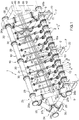
- the number 1 generically indicates, overall, a biogas collection plant consisting of a single biogas collection station to collect the biogas generated by the natural fermentation of organic solid waste masses stored in capturing wells, known per se and therefore not illustrated.
- the plant 1, i.e. the collection station comprises a plurality of collection units 2, in this case twelve collection units 2, which are connected to respective capturing wells, are mounted parallel to one another and are aligned with one another in a given direction 3.
- each collection unit 2 comprises a substantially cylindrical inlet sleeve 4, which has a longitudinal axis 5 parallel to the direction 3, is aligned with the inlet sleeves 4 of the other collection units 2 in the direction 3, is mechanically connected to two adjacent inlet sleeves 4, and is separated in a fluid-dynamic manner from each adjacent inlet sleeve 4 by means of a substantially circular plate 6 mounted orthogonally to the axis 5.
- a plate 6 is provided to close each of the two outer inlet sleeves 4 ( figure 1 ).
- Each supporting device 7 further comprises a box guide 8, which is fixed to the respective plate 6, extends in a direction 9 transverse to the direction 3, and is engaged slidingly by a slide 10 provided with a supporting foot 11 mounted at a lower free end of the slide 10 projecting on the outside of the guide 8.
- the position of the slides 10, and therefore of the feet 11 along the relative guides 8 in the direction 9, is adjusted to maintain the direction 3 in a horizontal position and the direction 9 in a vertical position so as to guarantee correct positioning of the plant 1 on the ground.
- Each inlet sleeve 4 is provided with an inlet pipe 12 and an outlet pipe 13.
- the inlet pipe 12 extends transversally to the axis 5, projecting radially towards the outside from the inlet sleeve 4, and can be connected to the relative capturing well to feed the biogas generated in the capturing well into the inlet sleeve 4.
- the outlet pipe 13 extends in the direction 9 and projects radially downwards from the outer surface of the inlet sleeve 4 to discharge the condensate generated by the biogas inside the inlet sleeve 4 to the outside of the collection unit 2.
- Each collection unit 2 comprises a feeding pipe 14, which projects radially towards the outside from the relative inlet sleeve 4, extends in a direction 15 inclined by an angle different from 0°, preferably approximately 30°, with respect to the direction 9, is parallel to the feeding pipes 14 of the other collection units 2, and comprises, in this case, three portions 16a, 16b, 16c connected to one another in a fluid-dynamic manner.
- the portion 16a is an inlet portion connected in a fluid-dynamic manner to the relative inlet sleeve 4,
- the portion 16b is an intermediate portion provided with a flow rate control valve 17 of known type, and the portion 16c is an outlet portion.
- the plant 1 comprises a manifold 18 for collection of the biogas fed through the inlet sleeves 4 and along the feeding pipes 14.
- the manifold 18 comprises a main pipe 19, which extends in the direction 3, and comprises, in turn, four portions 20 connected to one another in a fluid-dynamic manner.
- the manifold 18 comprises, for each feeding pipe 14, a secondary pipe 21, which extends in the direction 15, to connect in a fluid-dynamic manner the main pipe 19 to the feeding pipe 14.
- the inlet sleeves 4, the support devices 7, and the manifold 18 define a first portion 22 of a support structure 23 of the plant 1 further comprising a second portion 24 adapted to stabilize the first portion 22 and comprising, in turn, two tubular support frames 25, which are arranged on opposite sides of the assembly formed by the inlet sleeves 4 and manifold 18 in the direction 3 and have a substantially triangular form.
- each frame 25 comprises three four-way couplings 26a, 26b and 26c connected in a fluid-dynamic manner to one another in pairs by means of relative intermediate pipes 27a, 27b and 27c.
- the pipe 27a is parallel to the direction 15
- the pipe 27b is substantially orthogonal to the directions 3 and 9
- the pipe 27c is arranged according to an angle substantially equal to 60° with respect to the pipes 27a and 27b.
- the coupling 26a is connected in a fluid-dynamic manner to a relative free end of the manifold 18, the coupling 26b is connected to a relative outer inlet sleeve 4 by interposition of the plate 6 of the relative support device 7, and the coupling 26c is connected in a fluid-dynamic manner to a relative free end of a pipe 28 of the second portion 24 which extends parallel to the direction 3.
- each coupling 26c is connected to the pipe 28 by interposition of an annular disc 29 defining part of a relative support device 30, which further comprises a box guide 31, which is fixed to the disc 29, extends in the direction 9, and is engaged slidingly by a slide 32 provided with a supporting foot 33 mounted at a lower free end of the slide 32 projecting on the outside of the guide 31.
- the pipe 28 comprises two portions 34 connected to each other by interposition of the disc 29 of another support device 30. The position of the slides 32 and, therefore, of the feet 33 along the relative guides 31 in the direction 9 is adjusted analogously to what is described for the support devices 7 and for the same purpose.
- each frame 25 is provided with three outlet pipes 35 arranged at different heights in the direction 9 to discharge to the outside of the plant 1 at least part of the condensate generated by the biogas inside the manifold 18, the frames 25 and the pipe 28.
- the biogas generated inside the above-mentioned capturing wells enters the inlet sleeves 4 and passes through, in the following order, the feeding pipes 14, the manifold 18, the frames 25 and the pipe 28, and lastly is discharged to the outside of the plant 1 by means of at least one outlet (not illustrated) obtained in the manifold 18 and/or in the pipe 28 and/or in one of the frames 25.
- the fluid-dynamic connection between the manifold 18 and the frames 25 and between the frames 25 and the pipe 28 allows the inlet sleeves 4 and the manifold 18 to define part of the support structure 23 and the biogas and/or the condensate generated by the biogas to flow into the frames 25 and pipe 28 and to give the support structure 23 a weight sufficient to stabilize the entire plant 1, avoiding the use of an auxiliary independent support structure on which to mount the collection units 2 and the manifold 18.
- the support structure 23 is, therefore, a modular self-supporting structure, which incorporates inside it the inlet sleeves 4 and the manifold 18, has a relatively high versatility and flexibility, is symmetrical with respect to a substantially vertical plane of symmetry passing through the manifold 18, and can be mounted directly in the place of installation of the plant 1, considerably reducing the relative storage and transport costs.
- the plant 1 comprises a control system to automatically regulate capturing of the biogas via the plant 1.
- the control system comprises, for each collection unit 2, an electric actuator 36, which is coupled to the relative valve 17 to control the opening thereof, and a calibrated flange 37, which is arranged in the relative inlet pipe 12.
- Figure 1 illustrates only an actuator 36 for the sake of simplicity.
- Each actuator 36 consists, for example, of 24 volt stepper motors. Indicating the percentage opening of the valve 17 by APE, the actuator 36 controls the opening APE from 0% to 100% in steps, for example, of 2.5%.
- control system comprises, shared between all the collection units 2: a control board 38, which houses a pressure sensor 39, a methane sensor 40, an oxygen sensor 41 and an electronic control unit 42 adapted to control the actuators 36 to regulate the opening of the respective valves 17 according to the processing of measurements taken by the sensors 39-41; two pressure monitoring networks 43 and 44, which connect in a fluid-dynamic manner the pressure sensor 39 to two points 12a and 12b of each inlet pipe 12 located upstream and downstream respectively of the relative calibrated flange 37 to allow measurement of the differential pressure P between the points 12a and 12b and the flow rate Q of biogas in the inlet pipe 12; and a chemical monitoring network 51, which connects in a fluid-dynamic manner the methane and oxygen sensors 40 and 41 to each inlet sleeve 4 to allow measurement of the percentage concentration of methane, indicated below by CH4, and the percentage concentration of oxygen, indicated below by O2, in the biogas mixture present in the inlet sleeve 4.
- a control board 38 which houses a pressure sensor 39
- Each pressure monitoring network 43, 44 comprises a respective common pipe 45, 46 and, for each collection unit 2, a peripheral pipe 47, 48 connecting the respective point 12a, 12b of the relative inlet pipe 12 to the common pipe 45, 46.
- Each peripheral pipe 47, 48 is provided with a respective solenoid valve 49, 50 ( figure 2 ) controlled by the control unit 42 to allow or block circulation of the biogas of the peripheral pipe 47, 48.
- the chemical monitoring network 51 comprises a respective common pipe 52 and, for each collection unit 2, a peripheral pipe 53 connecting the relative inlet sleeve 4 to the common pipe 52.
- Each peripheral pipe 53 is provided with a respective solenoid valve 54 ( figure 2 ) controlled by the control unit 42 to allow or block circulation of the biogas of the peripheral pipe 53.
- the control system obviously comprises an electrical network (not illustrated) to wire the actuators 36 and the solenoid valves 49, 50 and 54 to the control board 38.
- the solenoid valves 49, 50 and 54 are normally closed.
- the control unit 42 calculates the flow rate Q of each collection unit 2 as a function of the differential pressure P relative to the same collection unit 2 and the internal diameter of the calibrated flange 37.
- the control unit 42 is configured to measure the parameters P, Q, CH4 and O2 for each collection unit 2 following two simultaneous time patterns.
- the measurements of the parameters P and Q are indirect, in the sense that, as explained previously, they are obtained by calculating them from the direct measurements of the pressures Pb and Pa.
- values measured of the parameters P, Q, CH4 and O2 are stored in a local memory of the control board 38, for example a memory 55 integrated in the control unit 42.
- a first time pattern consists in assigning, to the collection units 2, respective time intervals (timeslots) ⁇ Ti of equal duration and adjacent to one other so as to form a certain period of time TP1, the duration of which is equal to the sum of the time intervals ⁇ Ti and, within each time interval ⁇ Ti, controlling the opening of the solenoid valves 49, 50 and 54 of the relative collection unit 2 to measure the parameters P, Q, CH4 and O2 relative to said collection unit 2, processing the values measured and controlling the actuator 36 as a function of said processing to regulate the parameter APE, i.e. the percentage opening of the respective valve 17.
- the measurements of the parameters P, Q, CH4 and O2 are repeated cyclically on all the collection units 2 according to the period TP1.
- the period TP1 divided into the time intervals ⁇ Ti defines a first cycle of measurements performed for all the collection units 2 in sequence which is repeated with period TP1.
- the time interval ⁇ Ti has a value selected from the range of values between 2 and 10 minutes to allow the measurements on a relative collection unit 2 and, at the same time, wait for a certain stabilization of the relative capturing well.
- control unit 42 is configured to measure the parameters P, Q, CH4 and O2 and process the values measured of the relative collection unit 2 according to two analysis methods described below.
- the control unit 42 controls the solenoid valves 49, 50 and 54 so as to measure, in the following order, the differential pressure P, the flow rate Q and lastly the concentrations of methane CH4 and oxygen O2.
- the value measured of a parameter P, Q, CH4, O2 is compared with a relative predefined interval of values ⁇ P, ⁇ Q, ⁇ CH4, ⁇ O2, which is normally the same for all the collection units 2.
- the intervals ⁇ P, ⁇ Q, ⁇ CH4 and ⁇ O2 comprise values of the relative parameters P, Q, CH4 and O2 which correspond to a normal behaviour of a capturing well.
- the interval ⁇ CH4 is between 1% and 50% and the interval ⁇ O2 is between 1% and 10%.
- the control unit 42 proceeds with measurement of the following parameter, otherwise it signals and records said event as a fault associated with the collection unit 2 in question and does not proceed with measurement of the other parameters that follow in the predefined order.
- the fault is recorded in the memory 55.
- the cause of said fault can be, for example, a mechanical problem with the valve 17, or obstruction of an inlet pipe 12.
- the recording of a fault for a certain collection unit 2 entails the execution of a specific fault resolution action on the relative valve 17 which aims to resolve the fault, i.e. ensure that the parameters P, Q, CH4 and O2 return permanently within the relative intervals ⁇ P, ⁇ Q, ⁇ CH4 and ⁇ O2.
- the type of fault resolution action depends on which parameter P, Q, CH4, O2 lies outside the relative interval ⁇ P, ⁇ Q, ⁇ CH4 and ⁇ O2 and on the entity of the variance of the parameter from the relative interval.
- control unit 42 controls the relative actuator 36 to perform, on the relative valve 17, an action selected from a group of actions comprising for example:
- the prolonged total closing of the valve 17 can be re-set manually or automatically after a certain time interval greater than the time period TP1.
- the temporary total closing and the temporary total opening of the valve 17 have durations which can be selected from an interval, for example between 15 and 60 s.
- the control unit 14 selects the action to be performed on the valve 17 and the time duration of said action according to which parameter lies outside the relative interval and how far it lies outside said interval.
- control unit 42 proceeds with the second analysis method.
- measurement of the parameters CH4 and O2 requires much more time than measurement of the parameters P and Q.
- measurement of the parameters CH4 and O2 requires approximately at least 2 minutes whereas measurement of the parameters P and Q requires approximately 20 seconds. Consequently, at the end of measurement of the parameters CH4 and O2, the parameters P and Q could have undergone a significant variation.
- the control unit 42 determines a variable value of the parameter APE according to the combination of values measured of the parameters CH4 and O2 so as to maximize the parameter CH4, and consequently controls the actuator 36 to regulate opening of the relative valve 17.
- the values measured of the parameters CH4 and O2 used for determination of the parameter APE are those obtained with the first analysis method.
- the control unit 42 controls the solenoid valves 49 and 50 to measure the parameters P and Q again and compare the relative new values measured with the previous values measured, stored in the memory 55, to verify whether there is a variance greater than the relative tolerances ⁇ P and ⁇ Q between the new and the previous values.
- control unit 42 If one or both the variances of the parameters P and Q are outside the relative tolerances ⁇ P and ⁇ Q , then the control unit 42 records said event as a fault associated with the collection unit 2 in question and carries out a specific fault resolution action on the relative valve 17, of the same type as those described in relation to the first analysis method; otherwise the control unit 42 does nothing until the end of the relative time interval ⁇ Ti.
- the ultimate purpose of the adjustment of the valves 17 following the second analysis method is not so much to maximize for its own sake the parameter CH4 for each collection unit 2, but to maximize the calorific value of the biogas circulating in the collection unit 2, i.e. to maximize the parameter CH4 and at the same time guarantee the time stability of the parameters P and Q.
- the object of the second analysis method is to maximize the calorific value of the biogas sucked in by each collection unit 2 compatibly with the capacity of the relative capturing well to supply biogas.
- the control unit 42 periodically controls opening of the solenoid valves 49 and 50 of all the collection units 2, in sequence one after the other, excluding the one which is analysed in the same time period following the first time pattern, according to a time period TP2 shorter than TP1, to measure the parameters P and Q relative to all the collection units 2.
- the time period TP2 is greater than or equal to the time required for measurement of the parameters P and Q, which is between approximately 15 and 30 seconds, multiplied by the number of collection units 2 of the plant 1.
- the second time pattern is simultaneous with the first time pattern and has the purpose of acquiring values measured of the parameters P and Q of all the collection units 2 at a higher rate than the one defined by the first measurement cycle.
- the second time pattern defines a second measurement cycle relative to the parameters P and Q of all the collection units 2. Since the common pipes 46 and 47 have to be shared with the first measurement cycle, the second measurement cycle must necessarily be synchronized with the first measurement cycle to be able to "skip" the collection unit 2 associated with the interval ⁇ Ti during which said first measurement cycle is being performed.
- the control unit 42 stores the values measured of the parameters P and Q in the memory 55 and compares the new values measured with the previous values measured relative to the previous cycle to verify whether there is a variance greater than the relative tolerances ⁇ P and ⁇ Q between the new values and the previous values. If one or both the variances of the parameters P and Q exceed the relative tolerances ⁇ P and ⁇ Q , then the control unit 42 records said event as a fault associated with the collection unit 2 in question and performs a specific fault resolution action on the relative valve 17, of the same type as those described in relation to the first analysis method.
- the control system of the plant 1 is without the calibrated flanges 37 and the pressure monitoring network 44 and comprises a total pressure monitoring pipe, which connects in a fluid-dynamic manner the pressure sensor 39 to the four-way coupling 26a (the higher one) of one of the frames 25 or to one of the portions 20 of the main pipe 19 of the manifold 18 and is provided with a respective solenoid valve controlled by the control unit 42 to allow measurement of the total pressure Ptot inside the manifold 18. Consequently, each collection unit 2 has one single pressure measurement point, i.e. point 12a.
- the control unit 42 is able to measure indirectly the opening APE of each valve 17 from knowledge of the angular position of the relative actuator 36.
- each peripheral pipe 47 of the sole pressure monitoring network 43 is connected at any point of the fluid-dynamic path defined by the relative collection unit 2 upstream of the valve 17, with respect to the direction of circulation of the biogas inside the relative feeding pipe 14, for example at a point of the feeding pipe 14 located between the valve 17 and the inlet sleeve 4.
- the chemical monitoring network 54 comprises a further peripheral pipe, which connects in a fluid-dynamic manner the common pipe 52 to the four-way coupling 26a (the higher one) of one of the frames 25 or to one of the portions 20 of the main pipe 19 of the manifold 18 and is provided with a respective solenoid valve controlled by the control unit 42 to allow measurement of the total concentration of methane CH4tot and the total concentration of oxygen O2tot inside the manifold 18.
- the control unit 42 is configured to vary the intervals ⁇ CH4 and ⁇ O2 as a function of the values measured of total concentration of methane CH4tot and total concentration of oxygen O2tot in order to optimize the performance of the plant 1 in relation to the overall characteristics of the capturing wells connected to said plant 1.
- the control system of the plant 1 comprises the above-mentioned total pressure monitoring pipe to measure the total pressure Ptot inside the manifold 18,
- the chemical monitoring network 54 comprises the above-mentioned further peripheral pipe to measure the total concentration of methane CH4tot and the total concentration of oxygen O2tot inside the manifold 18,
- the control unit 42 is configured to vary the intervals ⁇ P, ⁇ CH4 and ⁇ O2 as a function of the total pressure values measured Ptot, total concentration of methane CH4tot and total concentration of oxygen O2tot in order to optimize the performance of the plant 1 in relation to the overall characteristics of the capturing wells connected to said plant 1.
Landscapes
- Engineering & Computer Science (AREA)
- Chemical & Material Sciences (AREA)
- Wood Science & Technology (AREA)
- Health & Medical Sciences (AREA)
- Life Sciences & Earth Sciences (AREA)
- Bioinformatics & Cheminformatics (AREA)
- Organic Chemistry (AREA)
- Zoology (AREA)
- Environmental & Geological Engineering (AREA)
- Biochemistry (AREA)
- Biomedical Technology (AREA)
- Microbiology (AREA)
- Biotechnology (AREA)
- General Engineering & Computer Science (AREA)
- General Health & Medical Sciences (AREA)
- Genetics & Genomics (AREA)
- Sustainable Development (AREA)
- Analytical Chemistry (AREA)
- Apparatus Associated With Microorganisms And Enzymes (AREA)
- Treatment Of Sludge (AREA)
- Sampling And Sample Adjustment (AREA)
- Preparation Of Compounds By Using Micro-Organisms (AREA)
- Automatic Analysis And Handling Materials Therefor (AREA)
- Separation Of Gases By Adsorption (AREA)
Abstract
Description
- The present invention concerns a system to control a biogas collection plant.
- In the technical field of waste disposal, it is known that the biogas generated by the natural fermentation of solid organic waste masses contained in storage wells, also known as biogas capturing wells, is extracted, and the biogas extracted from the wells is collected by means of a biogas collection plant. The biogas capturing wells together with the biogas collection plant form a so-called biogas capturing system.
- A landfill in general comprises a large number of wells, in the order of fifteen per hectare of landfill surface. The biogas collection plant is composed of several biogas collection stations, each of which is connected to the large number of wells, in general 10 to 20, by means of pipes to collect the biogas produced by said wells. In the biogas collection stations, a first discharge of the condensate generated by the biogas is performed.
- The wells are different from one another and the minimum parameters that must be considered to optimize capturing of the biogas are the flow rate, the concentration of methane and oxygen in the biogas mixture and the depression applied to the well for the capturing.
- Regulation of the biogas capturing by the wells is performed manually for each well, at best once every two days, according to manual analyses of flow rate, depression and concentration of methane and oxygen in the biogas using portable instruments which can be connected at predefined points of the biogas collection stations. Complete manual regulation of each well requires approximately 10 minutes.
- A medium-sized landfill in general has a capturing system consisting of approximately 120 wells connected to approximately 10 biogas collection stations. The analysis and manual regulation of an entire capturing system obviously results in low efficiency and precision. In particular, the regulation technique described above has the following problems:
- the interpretation of the regulation is subjective, and therefore the efficiency of the capturing system depends on the ability of the operator in charge;
- the capturing system is not able to track the inevitable physical changes in the biogas throughout the day and any variations in suction conditions in the capturing lines during the day due to imperfect operation of the machines that generate the depression in the pipes of said lines; and
- impossibility of knowing the status of the capturing lines in terms of presence or absence of condensate, which limits capturing of the biogas.
- The object of the present invention is to provide a system to control a biogas collection plant, which is free from the drawbacks described above and, at the same time, is easy and inexpensive to produce.
- According to the present invention, a system to control a biogas collection plant are provided, as defined in the attached claims.
- The present invention will now be described with reference to the accompanying drawings, which illustrate a non-limiting embodiment example thereof, in which:
-
figure 1 is a schematic perspective view of a biogas collection plant comprising a control system of the present invention; -
figure 2 is a lateral view of a first detail offigure 1 ; -
figure 3 is a perspective view of a second detail offigure 1 ; -
figure 4 is a lateral view of a third detail offigure 1 ; and -
figure 5 is a lateral view of a fourth detail offigure 1 . - In
figure 1 , the number 1 generically indicates, overall, a biogas collection plant consisting of a single biogas collection station to collect the biogas generated by the natural fermentation of organic solid waste masses stored in capturing wells, known per se and therefore not illustrated. The plant 1, i.e. the collection station, comprises a plurality ofcollection units 2, in this case twelvecollection units 2, which are connected to respective capturing wells, are mounted parallel to one another and are aligned with one another in a givendirection 3. - With reference to
figures 1 ,2 and 3 , eachcollection unit 2 comprises a substantiallycylindrical inlet sleeve 4, which has alongitudinal axis 5 parallel to thedirection 3, is aligned with theinlet sleeves 4 of theother collection units 2 in thedirection 3, is mechanically connected to twoadjacent inlet sleeves 4, and is separated in a fluid-dynamic manner from eachadjacent inlet sleeve 4 by means of a substantiallycircular plate 6 mounted orthogonally to theaxis 5. Aplate 6 is provided to close each of the two outer inlet sleeves 4 (figure 1 ). - The
plate 6 interposed between the twocentral inlet sleeves 4 and the twoplates 6 closing theouter inlet sleeves 4 each define part of a respective supportingdevice 7 for the plant 1. Each supportingdevice 7 further comprises abox guide 8, which is fixed to therespective plate 6, extends in adirection 9 transverse to thedirection 3, and is engaged slidingly by aslide 10 provided with a supportingfoot 11 mounted at a lower free end of theslide 10 projecting on the outside of theguide 8. The position of theslides 10, and therefore of thefeet 11 along therelative guides 8 in thedirection 9, is adjusted to maintain thedirection 3 in a horizontal position and thedirection 9 in a vertical position so as to guarantee correct positioning of the plant 1 on the ground. - Each
inlet sleeve 4 is provided with aninlet pipe 12 and anoutlet pipe 13. Theinlet pipe 12 extends transversally to theaxis 5, projecting radially towards the outside from theinlet sleeve 4, and can be connected to the relative capturing well to feed the biogas generated in the capturing well into theinlet sleeve 4. Theoutlet pipe 13 extends in thedirection 9 and projects radially downwards from the outer surface of theinlet sleeve 4 to discharge the condensate generated by the biogas inside theinlet sleeve 4 to the outside of thecollection unit 2. - Each
collection unit 2 comprises afeeding pipe 14, which projects radially towards the outside from therelative inlet sleeve 4, extends in adirection 15 inclined by an angle different from 0°, preferably approximately 30°, with respect to thedirection 9, is parallel to thefeeding pipes 14 of theother collection units 2, and comprises, in this case, threeportions portion 16a is an inlet portion connected in a fluid-dynamic manner to therelative inlet sleeve 4, theportion 16b is an intermediate portion provided with a flowrate control valve 17 of known type, and theportion 16c is an outlet portion. - With particular reference to
figure 1 , the plant 1 comprises amanifold 18 for collection of the biogas fed through theinlet sleeves 4 and along thefeeding pipes 14. Themanifold 18 comprises amain pipe 19, which extends in thedirection 3, and comprises, in turn, fourportions 20 connected to one another in a fluid-dynamic manner. Themanifold 18 comprises, for eachfeeding pipe 14, asecondary pipe 21, which extends in thedirection 15, to connect in a fluid-dynamic manner themain pipe 19 to thefeeding pipe 14. - The
inlet sleeves 4, thesupport devices 7, and themanifold 18 define afirst portion 22 of asupport structure 23 of the plant 1 further comprising asecond portion 24 adapted to stabilize thefirst portion 22 and comprising, in turn, twotubular support frames 25, which are arranged on opposite sides of the assembly formed by theinlet sleeves 4 andmanifold 18 in thedirection 3 and have a substantially triangular form. - With reference to
figures 1 and4 , eachframe 25 comprises three four-way couplings intermediate pipes pipe 27a is parallel to thedirection 15, thepipe 27b is substantially orthogonal to thedirections pipe 27c is arranged according to an angle substantially equal to 60° with respect to thepipes frame 25, thecoupling 26a is connected in a fluid-dynamic manner to a relative free end of themanifold 18, thecoupling 26b is connected to a relativeouter inlet sleeve 4 by interposition of theplate 6 of therelative support device 7, and thecoupling 26c is connected in a fluid-dynamic manner to a relative free end of apipe 28 of thesecond portion 24 which extends parallel to thedirection 3. - With reference to
figures 1 and5 , eachcoupling 26c is connected to thepipe 28 by interposition of anannular disc 29 defining part of arelative support device 30, which further comprises abox guide 31, which is fixed to thedisc 29, extends in thedirection 9, and is engaged slidingly by aslide 32 provided with a supportingfoot 33 mounted at a lower free end of theslide 32 projecting on the outside of theguide 31. Furthermore, thepipe 28 comprises two portions 34 connected to each other by interposition of thedisc 29 of anothersupport device 30. The position of theslides 32 and, therefore, of thefeet 33 along therelative guides 31 in thedirection 9 is adjusted analogously to what is described for thesupport devices 7 and for the same purpose. - With particular reference to
figure 4 , eachframe 25 is provided with threeoutlet pipes 35 arranged at different heights in thedirection 9 to discharge to the outside of the plant 1 at least part of the condensate generated by the biogas inside themanifold 18, theframes 25 and thepipe 28. - In use, the biogas generated inside the above-mentioned capturing wells enters the
inlet sleeves 4 and passes through, in the following order, thefeeding pipes 14, themanifold 18, theframes 25 and thepipe 28, and lastly is discharged to the outside of the plant 1 by means of at least one outlet (not illustrated) obtained in themanifold 18 and/or in thepipe 28 and/or in one of theframes 25. - The fluid-dynamic connection between the
manifold 18 and theframes 25 and between theframes 25 and thepipe 28 allows theinlet sleeves 4 and themanifold 18 to define part of thesupport structure 23 and the biogas and/or the condensate generated by the biogas to flow into theframes 25 andpipe 28 and to give the support structure 23 a weight sufficient to stabilize the entire plant 1, avoiding the use of an auxiliary independent support structure on which to mount thecollection units 2 and themanifold 18. - The
support structure 23 is, therefore, a modular self-supporting structure, which incorporates inside it theinlet sleeves 4 and themanifold 18, has a relatively high versatility and flexibility, is symmetrical with respect to a substantially vertical plane of symmetry passing through themanifold 18, and can be mounted directly in the place of installation of the plant 1, considerably reducing the relative storage and transport costs. - According to the present invention, with reference to
figures 1 and2 , the plant 1 comprises a control system to automatically regulate capturing of the biogas via the plant 1. The control system comprises, for eachcollection unit 2, anelectric actuator 36, which is coupled to therelative valve 17 to control the opening thereof, and acalibrated flange 37, which is arranged in therelative inlet pipe 12.Figure 1 illustrates only anactuator 36 for the sake of simplicity. Eachactuator 36 consists, for example, of 24 volt stepper motors. Indicating the percentage opening of thevalve 17 by APE, theactuator 36 controls the opening APE from 0% to 100% in steps, for example, of 2.5%. - Furthermore, the control system comprises, shared between all the collection units 2: a
control board 38, which houses apressure sensor 39, amethane sensor 40, anoxygen sensor 41 and anelectronic control unit 42 adapted to control theactuators 36 to regulate the opening of therespective valves 17 according to the processing of measurements taken by the sensors 39-41; twopressure monitoring networks pressure sensor 39 to twopoints 12a and 12b of eachinlet pipe 12 located upstream and downstream respectively of the relative calibratedflange 37 to allow measurement of the differential pressure P between thepoints 12a and 12b and the flow rate Q of biogas in theinlet pipe 12; and achemical monitoring network 51, which connects in a fluid-dynamic manner the methane andoxygen sensors inlet sleeve 4 to allow measurement of the percentage concentration of methane, indicated below by CH4, and the percentage concentration of oxygen, indicated below by O2, in the biogas mixture present in theinlet sleeve 4. - Each
pressure monitoring network common pipe collection unit 2, aperipheral pipe respective point 12a, 12b of therelative inlet pipe 12 to thecommon pipe peripheral pipe respective solenoid valve 49, 50 (figure 2 ) controlled by thecontrol unit 42 to allow or block circulation of the biogas of theperipheral pipe - The
chemical monitoring network 51 comprises a respectivecommon pipe 52 and, for eachcollection unit 2, aperipheral pipe 53 connecting therelative inlet sleeve 4 to thecommon pipe 52. Eachperipheral pipe 53 is provided with a respective solenoid valve 54 (figure 2 ) controlled by thecontrol unit 42 to allow or block circulation of the biogas of theperipheral pipe 53. - The control system obviously comprises an electrical network (not illustrated) to wire the
actuators 36 and thesolenoid valves control board 38. - The
solenoid valves control unit 42 is configured to selectively control opening of thesolenoid valves collection unit 2. In particular, indicating by Pa and Pb the pressures measured atpoints 15a and 12b respectively of eachcollection unit 2, thecontrol unit 42 calculates the differential pressure P relative to saidcollection unit 2 as the difference between the pressures Pb and Pa, or as a formula:
- The
control unit 42 calculates the flow rate Q of eachcollection unit 2 as a function of the differential pressure P relative to thesame collection unit 2 and the internal diameter of the calibratedflange 37. - The
control unit 42 is configured to measure the parameters P, Q, CH4 and O2 for eachcollection unit 2 following two simultaneous time patterns. The measurements of the parameters P and Q are indirect, in the sense that, as explained previously, they are obtained by calculating them from the direct measurements of the pressures Pb and Pa. In both said time patterns, values measured of the parameters P, Q, CH4 and O2 are stored in a local memory of thecontrol board 38, for example amemory 55 integrated in thecontrol unit 42. - A first time pattern consists in assigning, to the
collection units 2, respective time intervals (timeslots) ΔTi of equal duration and adjacent to one other so as to form a certain period of time TP1, the duration of which is equal to the sum of the time intervals ΔTi and, within each time interval ΔTi, controlling the opening of thesolenoid valves relative collection unit 2 to measure the parameters P, Q, CH4 and O2 relative to saidcollection unit 2, processing the values measured and controlling theactuator 36 as a function of said processing to regulate the parameter APE, i.e. the percentage opening of therespective valve 17. The measurements of the parameters P, Q, CH4 and O2 are repeated cyclically on all thecollection units 2 according to the period TP1. In other words, the period TP1 divided into the time intervals ΔTi defines a first cycle of measurements performed for all thecollection units 2 in sequence which is repeated with period TP1. - Normally, the time interval ΔTi has a value selected from the range of values between 2 and 10 minutes to allow the measurements on a
relative collection unit 2 and, at the same time, wait for a certain stabilization of the relative capturing well. - Within each time interval ΔTi, the
control unit 42 is configured to measure the parameters P, Q, CH4 and O2 and process the values measured of therelative collection unit 2 according to two analysis methods described below. - According to a first analysis method, the
control unit 42 controls thesolenoid valves collection units 2. The intervals ΔP, ΔQ, ΔCH4 and ΔO2 comprise values of the relative parameters P, Q, CH4 and O2 which correspond to a normal behaviour of a capturing well. Purely by way of example, the interval ΔCH4 is between 1% and 50% and the interval ΔO2 is between 1% and 10%. - If the value measured of the parameter P, Q, CH4, O2 is within the relative interval ΔP, ΔQ, ΔCH4, ΔO2, then the
control unit 42 proceeds with measurement of the following parameter, otherwise it signals and records said event as a fault associated with thecollection unit 2 in question and does not proceed with measurement of the other parameters that follow in the predefined order. The fault is recorded in thememory 55. The cause of said fault can be, for example, a mechanical problem with thevalve 17, or obstruction of aninlet pipe 12. - The recording of a fault for a
certain collection unit 2 entails the execution of a specific fault resolution action on therelative valve 17 which aims to resolve the fault, i.e. ensure that the parameters P, Q, CH4 and O2 return permanently within the relative intervals ΔP, ΔQ, ΔCH4 and ΔO2. The type of fault resolution action depends on which parameter P, Q, CH4, O2 lies outside the relative interval ΔP, ΔQ, ΔCH4 and ΔO2 and on the entity of the variance of the parameter from the relative interval. In other words, in the presence of a fault consisting of a parameter P, Q, CH4, O2 lying outside the relative interval ΔP, ΔQ, ΔCH4, ΔO2 for acertain collection unit 2, thecontrol unit 42 controls therelative actuator 36 to perform, on therelative valve 17, an action selected from a group of actions comprising for example: - prolonged total closing (APE = 0%);
- temporary total closing; and
- temporary total opening (APE = 100%).
- The prolonged total closing of the
valve 17 can be re-set manually or automatically after a certain time interval greater than the time period TP1. The temporary total closing and the temporary total opening of thevalve 17 have durations which can be selected from an interval, for example between 15 and 60 s. Thecontrol unit 14 selects the action to be performed on thevalve 17 and the time duration of said action according to which parameter lies outside the relative interval and how far it lies outside said interval. - If the values measured of all the parameters P, Q, CH4 and O2 lie within the relative intervals ΔP, ΔQ, ΔCH4 and ΔO2, then the
control unit 42 proceeds with the second analysis method. - It should be noted that measurement of the parameters CH4 and O2 requires much more time than measurement of the parameters P and Q. In fact, for one
single collection unit 2, measurement of the parameters CH4 and O2 requires approximately at least 2 minutes whereas measurement of the parameters P and Q requires approximately 20 seconds. Consequently, at the end of measurement of the parameters CH4 and O2, the parameters P and Q could have undergone a significant variation. - According to the second analysis method, the
control unit 42 determines a variable value of the parameter APE according to the combination of values measured of the parameters CH4 and O2 so as to maximize the parameter CH4, and consequently controls theactuator 36 to regulate opening of therelative valve 17. The values measured of the parameters CH4 and O2 used for determination of the parameter APE are those obtained with the first analysis method. - With the second analysis method, furthermore, after adjustment of the
valve 17 with the above-mentioned value of the parameter APE, thecontrol unit 42 controls thesolenoid valves memory 55, to verify whether there is a variance greater than the relative tolerances τP and τQ between the new and the previous values. If one or both the variances of the parameters P and Q are outside the relative tolerances τP and τQ, then thecontrol unit 42 records said event as a fault associated with thecollection unit 2 in question and carries out a specific fault resolution action on therelative valve 17, of the same type as those described in relation to the first analysis method; otherwise thecontrol unit 42 does nothing until the end of the relative time interval ΔTi. - The ultimate purpose of the adjustment of the
valves 17 following the second analysis method is not so much to maximize for its own sake the parameter CH4 for eachcollection unit 2, but to maximize the calorific value of the biogas circulating in thecollection unit 2, i.e. to maximize the parameter CH4 and at the same time guarantee the time stability of the parameters P and Q. In other words, the object of the second analysis method is to maximize the calorific value of the biogas sucked in by eachcollection unit 2 compatibly with the capacity of the relative capturing well to supply biogas. - In the second time pattern, the
control unit 42 periodically controls opening of thesolenoid valves collection units 2, in sequence one after the other, excluding the one which is analysed in the same time period following the first time pattern, according to a time period TP2 shorter than TP1, to measure the parameters P and Q relative to all thecollection units 2. The time period TP2 is greater than or equal to the time required for measurement of the parameters P and Q, which is between approximately 15 and 30 seconds, multiplied by the number ofcollection units 2 of the plant 1. The second time pattern is simultaneous with the first time pattern and has the purpose of acquiring values measured of the parameters P and Q of all thecollection units 2 at a higher rate than the one defined by the first measurement cycle. In other words, the second time pattern defines a second measurement cycle relative to the parameters P and Q of all thecollection units 2. Since thecommon pipes collection unit 2 associated with the interval ΔTi during which said first measurement cycle is being performed. - The
control unit 42 stores the values measured of the parameters P and Q in thememory 55 and compares the new values measured with the previous values measured relative to the previous cycle to verify whether there is a variance greater than the relative tolerances τP and τQ between the new values and the previous values. If one or both the variances of the parameters P and Q exceed the relative tolerances τP and τQ, then thecontrol unit 42 records said event as a fault associated with thecollection unit 2 in question and performs a specific fault resolution action on therelative valve 17, of the same type as those described in relation to the first analysis method. - According to a further embodiment not illustrated of the present invention, derived from the one illustrated by
figures 1 to 5 , the control system of the plant 1 is without the calibratedflanges 37 and thepressure monitoring network 44 and comprises a total pressure monitoring pipe, which connects in a fluid-dynamic manner thepressure sensor 39 to the four-way coupling 26a (the higher one) of one of theframes 25 or to one of theportions 20 of themain pipe 19 of the manifold 18 and is provided with a respective solenoid valve controlled by thecontrol unit 42 to allow measurement of the total pressure Ptot inside themanifold 18. Consequently, eachcollection unit 2 has one single pressure measurement point, i.e. point 12a. Thecontrol unit 42 is configured to calculate the differential pressure P as the difference between the pressure Ptot and the pressure Pa, i.e.:
control unit 42 is able to measure indirectly the opening APE of eachvalve 17 from knowledge of the angular position of therelative actuator 36. - According to variations of the above-mentioned further embodiment, each
peripheral pipe 47 of the solepressure monitoring network 43 is connected at any point of the fluid-dynamic path defined by therelative collection unit 2 upstream of thevalve 17, with respect to the direction of circulation of the biogas inside therelative feeding pipe 14, for example at a point of the feedingpipe 14 located between thevalve 17 and theinlet sleeve 4. - According to a further embodiment not illustrated of the present invention, derived from the one illustrated by
figures 1 to 5 , thechemical monitoring network 54 comprises a further peripheral pipe, which connects in a fluid-dynamic manner thecommon pipe 52 to the four-way coupling 26a (the higher one) of one of theframes 25 or to one of theportions 20 of themain pipe 19 of the manifold 18 and is provided with a respective solenoid valve controlled by thecontrol unit 42 to allow measurement of the total concentration of methane CH4tot and the total concentration of oxygen O2tot inside themanifold 18. Thecontrol unit 42 is configured to vary the intervals ΔCH4 and ΔO2 as a function of the values measured of total concentration of methane CH4tot and total concentration of oxygen O2tot in order to optimize the performance of the plant 1 in relation to the overall characteristics of the capturing wells connected to said plant 1. - According to a further embodiment not illustrated of the present invention, derived from the one illustrated by
figures 1 to 5 , the control system of the plant 1 comprises the above-mentioned total pressure monitoring pipe to measure the total pressure Ptot inside the manifold 18, thechemical monitoring network 54 comprises the above-mentioned further peripheral pipe to measure the total concentration of methane CH4tot and the total concentration of oxygen O2tot inside the manifold 18, and thecontrol unit 42 is configured to vary the intervals ΔP, ΔCH4 and ΔO2 as a function of the total pressure values measured Ptot, total concentration of methane CH4tot and total concentration of oxygen O2tot in order to optimize the performance of the plant 1 in relation to the overall characteristics of the capturing wells connected to said plant 1. - According to variations not illustrated:
- each feeding
pipe 14 and/or the manifold 18 and/or eachframe 25 and/or thepipe 28 are made in one single piece; - the
frames 25 are separated from the manifold 18 and thesecond portion 24 of thesupport structure 23 is filled and stabilized by means of a further fluid fed into thesecond portion 24; - the
inlet sleeves 4 are connected to one another in a fluid-dynamic manner; - the
outer inlet sleeves 4 are connected to theframes 25 in a fluid-dynamic manner; and - the pressure and chemical monitoring networks comprise pneumatic valves instead of the solenoid valves.
Claims (15)
- A control system to control a biogas collection plant (1) comprising a collection manifold (18) and a plurality of collection units (2), each of which is connected to a respective capturing well and comprises a respective feeding pipe (14) connected to the collection manifold (18) and a respective regulation valve (17) to adjust the biogas flow rate in the feeding pipe (14) itself; the control system comprising a plurality of actuators (36), each of which is designed to adjust the opening of a respective regulation valve (17), a control board (38), which comprises a pressure sensor (39), a methane sensor (40), an oxygen sensor (41) and a control unit (42), at least one first biogas pressure monitoring network (43), which is designed to connect the pressure sensor (39) to the collection units (2) in a fluid-dynamic manner and comprises, for each collection unit (2), a respective first control valve (49), and a biogas chemical monitoring network (51), which is designed to connect the methane sensor (40) and the oxygen sensor (41) to the collection units (2) in a fluid-dynamic manner and comprises, for each collection unit (2), a respective second control valve (54); the control unit (42) being configured to selectively control said first and second control valves (49, 54) so as to measure, for each collection unit (2), a first pressure (Pa), a methane concentration (CH4) and an oxygen concentration (O2) of the biogas in the collection unit (2), and to control the relative actuator (36) as a function of a processing of the measured values of the first pressure and the methane and oxygen concentrations (CH4, O2).
- A control system according to claim 1, wherein said first biogas pressure monitoring network (43) connects said pressure sensor (39) in first points (12a) of the collection units (2) upstream of the relative regulation valves (17), relative to the direction of circulation of the biogas in the relative feeding pipes (14), so that the first pressures (Pa) relate to the biogas in said first points (12a).
- A control system according to claim 1 or 2, wherein said control unit (42) is configured to determine, for each collection unit (2), a differential pressure (P) as a function of a reference pressure (Pb; Ptot) and of said first pressure (Pa), and a biogas flow rate (Q) in the collection unit (2) as a function of said first pressure (Pa), and to control the relative actuator (36) as a function of the differential pressure (P), the flow rate (Q) and the methane and oxygen concentrations (CH4, O2).
- A control system according to claims 2 and 3, wherein each collection unit (2) comprises an inlet pipe (12) that can be connected to the respective capturing well; the control system comprising a plurality of calibrated flanges (37), each of which can be mounted in the inlet pipe (12) of a respective collection unit (2) so that the relative first point (12a) is upstream of the calibrated flange (37), and a second biogas pressure monitoring network (44), which is designed to connect the pressure sensor (39) to the inlet pipes (12) in a fluid-dynamic manner in respective second points (12b) downstream of the relative calibrated flanges (37) and comprises, for each collection unit (2), a respective third control valve (50); said control unit (42) being configured to selectively control the third control valves (50) so as to measure, for each collection unit (2), said reference pressure (Pb) as the pressure of the biogas in the relative second point (12b) and to determine said flow rate (Q) as a function of the differential pressure (P) and of the inner diameter of the relative calibrated flange (37).
- A control system according to claim 3 and comprising a total biogas pressure monitoring pipe, which is designed to connect the pressure sensor (39) to the collection manifold (18) in a fluid-dynamic manner and is provided with a fourth control valve controlled by said control unit (42) so as to allow the reference pressure (Ptot) to be measured as the pressure of the biogas in the collection manifold (18); the control unit (42) being configured to determine said flow rate (Q) of each collection unit (2) as a function of the relative first pressure (Pa) and of the percentage opening of the relative regulation valve (17).
- A control system according to any of the claims from 1 to 5, wherein said control unit (42) is configured to selectively control said first and second control valves (49, 54) so as to carry out a first periodic cycle of measurements of parameters (Pa, P, Q, CH4, O2) of the biogas in the collection units (2) by means of said sensors (39-41) shared by all collection units (2), the first periodic cycle of measurements being divided into a plurality of time intervals (ΔTi) and the parameters (Pa, P, Q, CH4, O2) of a respective collection unit (2) being measured in each one of them, and a second periodic cycle of measurements of a subset of the parameters (Q, P) of the biogas of the collection units (2) by means of a subset of the sensors (39), the second cycle of measurements being simultaneous with and having a smaller periodicity than the first cycle of measurements; the control unit (42) being further configured to adjust, in each time interval (ΔTi), the opening of the regulation valve (17) of the relative collection unit (2) as a function of the processing of the measured values of the parameters (Pa, P, Q, CH4, O2) obtained in the time interval (ΔTi), and to detect possible faults in the collection units (2) as a function of the processing of the relative measured values of the subset of parameters (Q, P) obtained in the second cycle of measurements.
- A control system according to claim 6, wherein said subset of the of sensors comprises said pressure sensor (39).
- A control system according to claim 7, wherein said parameters comprise a pressure (Pa), a biogas methane concentration (CH4) and a biogas oxygen concentration (O2).
- A control system according to claim 7, wherein said parameters comprise a differential pressure (P), which is determined as a function of a reference pressure (Pb; Ptot) and a first pressure (Pa) measured in a first point (12a) of the collection unit (2), preferably upstream of the relative regulation valve (17) of the collection unit (2), relative to the direction of circulation of the biogas in the relative feeding pipe (14), and a flow rate (Q) of the biogas in the collection unit (2), which is determined as a function of the first pressure (Pa).
- A control system according to any of the claims from 6 to 9, wherein said control unit (42) is configured to carry out said first cycle of measurements by, for each time interval (ΔTi):- associating each one of said parameters (P, Q, CH4, O2) with a predetermined interval of values (ΔP, ΔQ, ΔCH4, ΔO2) indicating a normal behaviour of a capturing well; and- measuring each parameter (P, Q, CH4, O2) and comparing the measured value with the relative interval of values (ΔP, ΔQ, ΔCH4, ΔO2);the control unit (42) being also configured to adjust the opening of the regulation valve (17) of each collection unit (2) if the measured values of all parameters (P, Q, CH4, O2) lie within the relative intervals of values (ΔP, ΔQ, ΔCH4, ΔO2).
- A control system according to claim 10, wherein said control unit (42) is configured to carry out said first cycle of measurements by, for each time interval (ΔTi), recording a fault associated with the relative collection unit (2) if the measured value of at least one of said parameters (P, Q, CH4, O2) is outside of the relative interval of values (ΔP, ΔQ, ΔCH4, Δ02).
- A control system according to claim 10 or 11, wherein said control unit (42) is configured to measure each parameter (P, Q, CH4, O2) and compare the measured value with the relative interval of values (ΔP, ΔQ, ΔCH4, ΔO2) by:- measuring, in the following order, differential pressure (P), flow rate (Q), methane concentration (CH4) and oxygen concentration (O2);- for each measured parameter (P, Q, CH4, O2), comparing the measured value with the relative predetermined interval of values (ΔP, ΔQ, ΔCH4, ΔO2); and- moving on to the measurement of the following parameter (P, Q, CH4, O2), according to said order, only if the measured value lies within the relative predetermined value interval (ΔP, ΔQ, ΔCH4, ΔO2).
- A control system according to any of the claims from 6 to 12, wherein said parameters (P, Q, CH4, O2) comprise a biogas methane concentration (CH4) and a biogas oxygen concentration (O2); said control unit (42) being configured to adjust the opening of the regulation valve (17) of a collection unit (2) in a respective time interval (ΔTi) as a function of the combination of the measured values of the methane and oxygen concentrations (CH4, O2) obtained in the time interval (ΔTi), in such a way as to maximise the methane concentration (CH4).
- A control system according to any of the claims from 6 to 13, wherein said control unit (42) is configured to control, in each of said time intervals (ΔTi) of said first periodic cycle of measurements, the first and the second control valve (49, 54) of the relative collection unit (2) so as to allow measurement of said parameters (Pa, P, Q, CH4, O2) and to control, in said second periodic cycle of measurements, the first control valves (49) in sequence one after the other, excluding the valve of the collection unit (2) which in the same time period is analysed by the first measurement cycle, so as to allow measurement of said subset of parameters (Q, P) .
- A biogas collection plant comprising a collection manifold (18), a plurality of collection units (2), each of which is connectable to a respective capturing well and comprises a respective feeding pipe (14) connected to the collection manifold (18) and a respective regulation valve (17) to adjust the biogas flow rate in the feeding pipe (14) itself, and a control system according to any of the claims from 1 to 14.
Applications Claiming Priority (3)
| Application Number | Priority Date | Filing Date | Title |
|---|---|---|---|
| ITUB2015A005582A ITUB20155582A1 (en) | 2015-11-13 | 2015-11-13 | SYSTEM AND METHOD TO CHECK A BIOGAS COLLECTION SYSTEM |
| EP16822526.6A EP3374103B1 (en) | 2015-11-13 | 2016-11-14 | System and method to control a biogas collection plant |
| PCT/IB2016/056844 WO2017081671A1 (en) | 2015-11-13 | 2016-11-14 | System and method to control a biogas collection plant |
Related Parent Applications (2)
| Application Number | Title | Priority Date | Filing Date |
|---|---|---|---|
| EP16822526.6A Division EP3374103B1 (en) | 2015-11-13 | 2016-11-14 | System and method to control a biogas collection plant |
| EP16822526.6A Division-Into EP3374103B1 (en) | 2015-11-13 | 2016-11-14 | System and method to control a biogas collection plant |
Publications (2)
| Publication Number | Publication Date |
|---|---|
| EP3791970A1 true EP3791970A1 (en) | 2021-03-17 |
| EP3791970B1 EP3791970B1 (en) | 2025-12-17 |
Family
ID=55446992
Family Applications (2)
| Application Number | Title | Priority Date | Filing Date |
|---|---|---|---|
| EP16822526.6A Active EP3374103B1 (en) | 2015-11-13 | 2016-11-14 | System and method to control a biogas collection plant |
| EP20204847.6A Active EP3791970B1 (en) | 2015-11-13 | 2016-11-14 | System to control a biogas collection plant |
Family Applications Before (1)
| Application Number | Title | Priority Date | Filing Date |
|---|---|---|---|
| EP16822526.6A Active EP3374103B1 (en) | 2015-11-13 | 2016-11-14 | System and method to control a biogas collection plant |
Country Status (7)
| Country | Link |
|---|---|
| US (1) | US10512955B2 (en) |
| EP (2) | EP3374103B1 (en) |
| CN (1) | CN108430656B (en) |
| BR (1) | BR112018009679B1 (en) |
| ES (2) | ES2876273T3 (en) |
| IT (1) | ITUB20155582A1 (en) |
| WO (1) | WO2017081671A1 (en) |
Families Citing this family (4)
| Publication number | Priority date | Publication date | Assignee | Title |
|---|---|---|---|---|
| ITUB20155582A1 (en) | 2015-11-13 | 2017-05-13 | Antonini Marco Ditta Individuale | SYSTEM AND METHOD TO CHECK A BIOGAS COLLECTION SYSTEM |
| US10936870B2 (en) * | 2018-07-05 | 2021-03-02 | Iron Ox, Inc. | Method for selectively deploying sensors within an agricultural facility |
| US11221138B1 (en) | 2020-05-26 | 2022-01-11 | Wm Intellectual Property Holdings, L.L.C. | System and method for remote monitoring and control of landfill and recycling operations |
| IT202100031454A1 (en) * | 2021-12-15 | 2023-06-15 | Ecospray Tech Srl | SYSTEM FOR AUTOMATIC REGULATION OF GAS CAPTURED FROM WELLS |
Citations (4)
| Publication number | Priority date | Publication date | Assignee | Title |
|---|---|---|---|---|
| US4670148A (en) * | 1984-11-10 | 1987-06-02 | Reinhard Schneider | Apparatus and method for withdrawing gaseous decomposition products from a refuse dump |
| EP0904857A1 (en) * | 1997-09-17 | 1999-03-31 | Société publique d'Aide à la Qualité de l'Environnement, S.P.A.Q.U.E., Société Anonyme | Method and system for withdrawing gases produced by fermentable materials, particularly waste |
| US20010005812A1 (en) * | 1996-09-23 | 2001-06-28 | Landfill Gas & Environmental Products Inc. | Landfill monitoring and control system |
| US20110231099A1 (en) * | 2006-12-05 | 2011-09-22 | Charles Elkins | Portable gas monitor |
Family Cites Families (10)
| Publication number | Priority date | Publication date | Assignee | Title |
|---|---|---|---|---|
| IT1240196B (en) * | 1990-04-18 | 1993-11-27 | Servizi Ecologici S R L Ora Se | PLANT FOR THE CONTROLLED DISPOSAL OF WASTE AND ITS CONDUCTION PROCESS. |
| DE10120107C1 (en) * | 2001-04-25 | 2002-02-21 | Dieter Kress | Method and device for improved landfill management |
| US7198433B2 (en) * | 2004-07-22 | 2007-04-03 | Institute For Environmental Management, Inc | Landfill design and method for improved landfill gas capture |
| IL161011A (en) * | 2004-03-22 | 2006-12-10 | E E R Env Energy Resrc Israel | Apparatus and system for controlling the level of potential pollutants in a waste treatment plant |
| EP2346982B2 (en) * | 2008-11-15 | 2019-03-13 | MT-Energie Service GmbH | Device and method for regulating the gas supply or the gas transport in a gas storage system |
| CN201505499U (en) * | 2008-12-31 | 2010-06-16 | 青岛天人环境股份有限公司 | An integrated biogas purification device for biogas engineering |
| CN104357316B (en) * | 2010-04-12 | 2017-10-03 | Seab 能源有限公司 | The micro generation device and method of regenerative resource |
| CN102896132B (en) * | 2012-11-08 | 2015-10-28 | 城市建设研究院 | A kind of method determining household refuse landfill sites biogas air guide well sphere of action |
| US9062536B2 (en) * | 2013-01-02 | 2015-06-23 | Graco Minnesota Inc. | Devices and methods for landfill gas well monitoring and control |
| ITUB20155582A1 (en) | 2015-11-13 | 2017-05-13 | Antonini Marco Ditta Individuale | SYSTEM AND METHOD TO CHECK A BIOGAS COLLECTION SYSTEM |
-
2015
- 2015-11-13 IT ITUB2015A005582A patent/ITUB20155582A1/en unknown
-
2016
- 2016-11-14 EP EP16822526.6A patent/EP3374103B1/en active Active
- 2016-11-14 WO PCT/IB2016/056844 patent/WO2017081671A1/en not_active Ceased
- 2016-11-14 EP EP20204847.6A patent/EP3791970B1/en active Active
- 2016-11-14 US US15/775,785 patent/US10512955B2/en active Active
- 2016-11-14 ES ES16822526T patent/ES2876273T3/en active Active
- 2016-11-14 ES ES20204847T patent/ES3062658T3/en active Active
- 2016-11-14 BR BR112018009679-2A patent/BR112018009679B1/en active IP Right Grant
- 2016-11-14 CN CN201680066424.5A patent/CN108430656B/en active Active
Patent Citations (4)
| Publication number | Priority date | Publication date | Assignee | Title |
|---|---|---|---|---|
| US4670148A (en) * | 1984-11-10 | 1987-06-02 | Reinhard Schneider | Apparatus and method for withdrawing gaseous decomposition products from a refuse dump |
| US20010005812A1 (en) * | 1996-09-23 | 2001-06-28 | Landfill Gas & Environmental Products Inc. | Landfill monitoring and control system |
| EP0904857A1 (en) * | 1997-09-17 | 1999-03-31 | Société publique d'Aide à la Qualité de l'Environnement, S.P.A.Q.U.E., Société Anonyme | Method and system for withdrawing gases produced by fermentable materials, particularly waste |
| US20110231099A1 (en) * | 2006-12-05 | 2011-09-22 | Charles Elkins | Portable gas monitor |
Also Published As
| Publication number | Publication date |
|---|---|
| BR112018009679B1 (en) | 2021-06-08 |
| EP3374103B1 (en) | 2021-04-21 |
| EP3791970B1 (en) | 2025-12-17 |
| WO2017081671A1 (en) | 2017-05-18 |
| US10512955B2 (en) | 2019-12-24 |
| BR112018009679A8 (en) | 2019-02-26 |
| EP3374103A1 (en) | 2018-09-19 |
| ES2876273T3 (en) | 2021-11-12 |
| ITUB20155582A1 (en) | 2017-05-13 |
| BR112018009679A2 (en) | 2018-11-06 |
| US20180326464A1 (en) | 2018-11-15 |
| CN108430656A (en) | 2018-08-21 |
| ES3062658T3 (en) | 2026-04-13 |
| CN108430656B (en) | 2021-06-15 |
Similar Documents
| Publication | Publication Date | Title |
|---|---|---|
| EP3791970B1 (en) | System to control a biogas collection plant | |
| RU2434214C2 (en) | Method and apparatus for determining collection efficiency of filter device | |
| CN103127834B (en) | The method of the state of the multiple desalination membranes in desalination system and monitor force container | |
| HK1045185A1 (en) | Flowmeter calibration system with statistical optimization technique | |
| CN106774127A (en) | A kind of industrial park enterprise wastewater receives the intelligent monitoring system and monitoring method of pipe | |
| CN102384884A (en) | Sampling type size density measuring method | |
| KR101534244B1 (en) | Power control system for aeration tank using floating type wireless sensing apparatus for off gas | |
| CN209387613U (en) | Portable spray ammonia levels intelligent measure analysis system | |
| CN114544897A (en) | Environment remote supervision method and environment supervision system thereof | |
| CN115436594A (en) | Water quality measuring device for flowing water quality detection and measuring method thereof | |
| CN201754140U (en) | Slurry density measuring system of flue gas desulfurization apparatus | |
| US3811324A (en) | Proportional sampling apparatus and method | |
| CN204165805U (en) | A kind of refuse landfill soil profile gas automatic sampling device | |
| KR20180099032A (en) | Automatic Water Sampling Apparatus of Nonpoint Pollution Source | |
| HK1259861A1 (en) | System and method to control a biogas collection plant | |
| KR200495182Y1 (en) | Landfill gas capture methane concentration control system | |
| HK1259861B (en) | System and method to control a biogas collection plant | |
| CN109405907B (en) | A method and system for detecting gas emission flux | |
| CN217084654U (en) | Biochemical system water quality testing miniature detection station | |
| CN106089672B (en) | Compressor reliability detection method and device | |
| CN209264261U (en) | Automatic charging type oil network deduster detection device | |
| CN209399893U (en) | One kind being used for grid sewage-removing machine rope capacity measuring device | |
| CN106871997A (en) | A kind of water meter calibration equipment | |
| CN206563597U (en) | A kind of water meter calibration equipment | |
| CN217237555U (en) | Structural member stress performance testing and loading device using still water for loading |
Legal Events
| Date | Code | Title | Description |
|---|---|---|---|
| PUAI | Public reference made under article 153(3) epc to a published international application that has entered the european phase |
Free format text: ORIGINAL CODE: 0009012 |
|
| STAA | Information on the status of an ep patent application or granted ep patent |
Free format text: STATUS: THE APPLICATION HAS BEEN PUBLISHED |
|
| AC | Divisional application: reference to earlier application |
Ref document number: 3374103 Country of ref document: EP Kind code of ref document: P |
|
| AK | Designated contracting states |
Kind code of ref document: A1 Designated state(s): AL AT BE BG CH CY CZ DE DK EE ES FI FR GB GR HR HU IE IS IT LI LT LU LV MC MK MT NL NO PL PT RO RS SE SI SK SM TR |
|
| STAA | Information on the status of an ep patent application or granted ep patent |
Free format text: STATUS: REQUEST FOR EXAMINATION WAS MADE |
|
| 17P | Request for examination filed |
Effective date: 20210917 |
|
| RBV | Designated contracting states (corrected) |
Designated state(s): AL AT BE BG CH CY CZ DE DK EE ES FI FR GB GR HR HU IE IS IT LI LT LU LV MC MK MT NL NO PL PT RO RS SE SI SK SM TR |
|
| P01 | Opt-out of the competence of the unified patent court (upc) registered |
Effective date: 20230516 |
|
| STAA | Information on the status of an ep patent application or granted ep patent |
Free format text: STATUS: EXAMINATION IS IN PROGRESS |
|
| 17Q | First examination report despatched |
Effective date: 20230623 |
|
| GRAP | Despatch of communication of intention to grant a patent |
Free format text: ORIGINAL CODE: EPIDOSNIGR1 |
|
| STAA | Information on the status of an ep patent application or granted ep patent |
Free format text: STATUS: GRANT OF PATENT IS INTENDED |
|
| INTG | Intention to grant announced |
Effective date: 20250709 |
|
| GRAS | Grant fee paid |
Free format text: ORIGINAL CODE: EPIDOSNIGR3 |
|
| RAP3 | Party data changed (applicant data changed or rights of an application transferred) |
Owner name: ANTONINI MARCO DITTA INDIVIDUALE |
|
| GRAA | (expected) grant |
Free format text: ORIGINAL CODE: 0009210 |
|
| STAA | Information on the status of an ep patent application or granted ep patent |
Free format text: STATUS: THE PATENT HAS BEEN GRANTED |
|
| RAP1 | Party data changed (applicant data changed or rights of an application transferred) |
Owner name: ANTONINI, MARCO |
|
| RIN1 | Information on inventor provided before grant (corrected) |
Inventor name: ANTONINI, MARCO |
|
| AC | Divisional application: reference to earlier application |
Ref document number: 3374103 Country of ref document: EP Kind code of ref document: P |
|
| AK | Designated contracting states |
Kind code of ref document: B1 Designated state(s): AL AT BE BG CH CY CZ DE DK EE ES FI FR GB GR HR HU IE IS IT LI LT LU LV MC MK MT NL NO PL PT RO RS SE SI SK SM TR |
|
| REG | Reference to a national code |
Ref country code: CH Ref legal event code: F10 Free format text: ST27 STATUS EVENT CODE: U-0-0-F10-F00 (AS PROVIDED BY THE NATIONAL OFFICE) Effective date: 20251217 Ref country code: GB Ref legal event code: FG4D |
|
| REG | Reference to a national code |
Ref country code: DE Ref legal event code: R096 Ref document number: 602016094367 Country of ref document: DE |
|
| REG | Reference to a national code |
Ref country code: NL Ref legal event code: FP |
|
| REG | Reference to a national code |
Ref country code: LT Ref legal event code: MG9D |
|
| PG25 | Lapsed in a contracting state [announced via postgrant information from national office to epo] |
Ref country code: NO Free format text: LAPSE BECAUSE OF FAILURE TO SUBMIT A TRANSLATION OF THE DESCRIPTION OR TO PAY THE FEE WITHIN THE PRESCRIBED TIME-LIMIT Effective date: 20260317 |
|
| REG | Reference to a national code |
Ref country code: ES Ref legal event code: FG2A Ref document number: 3062658 Country of ref document: ES Kind code of ref document: T3 Effective date: 20260413 |
|
| PG25 | Lapsed in a contracting state [announced via postgrant information from national office to epo] |
Ref country code: FI Free format text: LAPSE BECAUSE OF FAILURE TO SUBMIT A TRANSLATION OF THE DESCRIPTION OR TO PAY THE FEE WITHIN THE PRESCRIBED TIME-LIMIT Effective date: 20251217 Ref country code: HR Free format text: LAPSE BECAUSE OF FAILURE TO SUBMIT A TRANSLATION OF THE DESCRIPTION OR TO PAY THE FEE WITHIN THE PRESCRIBED TIME-LIMIT Effective date: 20251217 |
|
| PG25 | Lapsed in a contracting state [announced via postgrant information from national office to epo] |
Ref country code: RS Free format text: LAPSE BECAUSE OF FAILURE TO SUBMIT A TRANSLATION OF THE DESCRIPTION OR TO PAY THE FEE WITHIN THE PRESCRIBED TIME-LIMIT Effective date: 20260317 |
|
| PG25 | Lapsed in a contracting state [announced via postgrant information from national office to epo] |
Ref country code: LV Free format text: LAPSE BECAUSE OF FAILURE TO SUBMIT A TRANSLATION OF THE DESCRIPTION OR TO PAY THE FEE WITHIN THE PRESCRIBED TIME-LIMIT Effective date: 20251217 |
|
| PG25 | Lapsed in a contracting state [announced via postgrant information from national office to epo] |
Ref country code: BG Free format text: LAPSE BECAUSE OF FAILURE TO SUBMIT A TRANSLATION OF THE DESCRIPTION OR TO PAY THE FEE WITHIN THE PRESCRIBED TIME-LIMIT Effective date: 20251217 |