EP3791702B1 - Supply station with door shield - Google Patents
Supply station with door shield Download PDFInfo
- Publication number
- EP3791702B1 EP3791702B1 EP19724031.0A EP19724031A EP3791702B1 EP 3791702 B1 EP3791702 B1 EP 3791702B1 EP 19724031 A EP19724031 A EP 19724031A EP 3791702 B1 EP3791702 B1 EP 3791702B1
- Authority
- EP
- European Patent Office
- Prior art keywords
- enclosure
- finger
- door structure
- bracket
- doorframe
- Prior art date
- Legal status (The legal status is an assumption and is not a legal conclusion. Google has not performed a legal analysis and makes no representation as to the accuracy of the status listed.)
- Active
Links
Images



Classifications
-
- H—ELECTRICITY
- H05—ELECTRIC TECHNIQUES NOT OTHERWISE PROVIDED FOR
- H05K—PRINTED CIRCUITS; CASINGS OR CONSTRUCTIONAL DETAILS OF ELECTRIC APPARATUS; MANUFACTURE OF ASSEMBLAGES OF ELECTRICAL COMPONENTS
- H05K9/00—Screening of apparatus or components against electric or magnetic fields
- H05K9/0007—Casings
- H05K9/0015—Gaskets or seals
- H05K9/0016—Gaskets or seals having a spring contact
-
- A—HUMAN NECESSITIES
- A61—MEDICAL OR VETERINARY SCIENCE; HYGIENE
- A61B—DIAGNOSIS; SURGERY; IDENTIFICATION
- A61B50/00—Containers, covers, furniture or holders specially adapted for surgical or diagnostic appliances or instruments, e.g. sterile covers
- A61B50/10—Furniture specially adapted for surgical or diagnostic appliances or instruments
-
- G—PHYSICS
- G06—COMPUTING OR CALCULATING; COUNTING
- G06K—GRAPHICAL DATA READING; PRESENTATION OF DATA; RECORD CARRIERS; HANDLING RECORD CARRIERS
- G06K17/00—Methods or arrangements for effecting co-operative working between equipments covered by two or more of main groups G06K1/00 - G06K15/00, e.g. automatic card files incorporating conveying and reading operations
- G06K17/0022—Methods or arrangements for effecting co-operative working between equipments covered by two or more of main groups G06K1/00 - G06K15/00, e.g. automatic card files incorporating conveying and reading operations arrangements or provisions for transferring data to distant stations, e.g. from a sensing device
- G06K17/0029—Methods or arrangements for effecting co-operative working between equipments covered by two or more of main groups G06K1/00 - G06K15/00, e.g. automatic card files incorporating conveying and reading operations arrangements or provisions for transferring data to distant stations, e.g. from a sensing device the arrangement being specially adapted for wireless interrogation of grouped or bundled articles tagged with wireless record carriers
-
- H—ELECTRICITY
- H05—ELECTRIC TECHNIQUES NOT OTHERWISE PROVIDED FOR
- H05K—PRINTED CIRCUITS; CASINGS OR CONSTRUCTIONAL DETAILS OF ELECTRIC APPARATUS; MANUFACTURE OF ASSEMBLAGES OF ELECTRICAL COMPONENTS
- H05K9/00—Screening of apparatus or components against electric or magnetic fields
- H05K9/0007—Casings
- H05K9/0009—Casings with provisions to reduce EMI leakage through the joining parts
-
- H—ELECTRICITY
- H05—ELECTRIC TECHNIQUES NOT OTHERWISE PROVIDED FOR
- H05K—PRINTED CIRCUITS; CASINGS OR CONSTRUCTIONAL DETAILS OF ELECTRIC APPARATUS; MANUFACTURE OF ASSEMBLAGES OF ELECTRICAL COMPONENTS
- H05K9/00—Screening of apparatus or components against electric or magnetic fields
- H05K9/0007—Casings
- H05K9/0015—Gaskets or seals
-
- A—HUMAN NECESSITIES
- A61—MEDICAL OR VETERINARY SCIENCE; HYGIENE
- A61B—DIAGNOSIS; SURGERY; IDENTIFICATION
- A61B50/00—Containers, covers, furniture or holders specially adapted for surgical or diagnostic appliances or instruments, e.g. sterile covers
- A61B50/10—Furniture specially adapted for surgical or diagnostic appliances or instruments
- A61B2050/105—Cabinets
Definitions
- the present invention generally relates to supply stations that are equipped for reading radio-frequency identification (“RFID”) tags and more particularly relates to supply stations with doors that shield radio frequency (“RF”) signals.
- RFID radio-frequency identification
- RF radio frequency
- Supply stations such as supply cabinets may be used for storing medical supplies.
- Medical supplies may be equipped with RFID tags and the supply cabinet may be equipped with RF transceivers to transmit RF signals to read RFID tags of medical supplies.
- the RF transceiver may detect received RF signals from the RFID tags to generate an inventory list of the medical supplies. Every time the medical supply door is closed the RF transmitter may transmit RF signals to read the RFID tags of remaining medical supplies to update the inventory list.
- GB2183920A discloses an electromagnetic seal arrangement for a door, comprising first and second metal contacts, one of which is associated with the door frame and the other of which is carrid by the door, the first contact including a resiliently displaceable contact region supported on both sides thereof, and the arrangement being such that as the door is closed the second contact approaches the displaceable region in a substantially perpendicular direction to make sealing contact therewith.
- US 5 894 106 A concerns an electronics cabinet with a shielding frame of sectional rails, with attached casings on the side rails as well as electrical contact springs between the shelving frames and the casings.
- US20170196128A1 relates generally to a container formed of a non-electrically-conducting substrate having an electrically-conductive component so that the container has an RF shield to attenuate RF energy in the container from leaking out of the container, and more particularly, to an RF shield that includes a tortuous path seal.
- CN207097134U is related to intelligent storage cabinet technical field, more particularly to a kind of medical goods and materials intelligence based on RFID technique Can cabinet.
- MOLYNEUX CHILD J W in "EMC - COMPARATIVE MERITS OF BERYLLIUM COPPER", ELECTRONIC ENGINEERING, MORGANGRAMPIAN LTD. LONDON, GB, vol. 64, no. 784, 1 April 1992 (1992-04-01), page 19, 21, XP000291113, ISSN: 0013-4902 ) relates to beryllium copper in electronic engineering.
- the RF signal may leak outside the supply cabinet or the transceiver may receive RF signals from outside the supply cabinet.
- the RF transceiver can read RFID tags of items outside the supply cabinet or even may read the RFID tags of items in neighboring supply cabinets. Therefore, it is desirable to seal the medical supply cabinet against RF signals going out or coming in.
- the body of the supply cabinet may be made of a material that attenuates RF signals.
- a door of the supply cabinet can also be made of a material to limit, restrict, or prevent RF signals from passing through it. It is also desirable to limit, restrict, or prevent RF signal leakage from the openings between the door of the supply cabinet and the supply cabinet body.
- the inventory list may be generated when the supply cabinet door closes.
- the supply items may be equipped with RFID tags or other tags that may be queried by sending RF signals.
- the supply cabinet may be equipped with a transceiver that may include a detector, a processor, and a memory, and the transceiver may send and receive RF signals to read the tags and to generate the inventory list.
- RF signals do not leak to outside of the supply cabinet and, in particular, RF signals may not leak from outside to inside of the supply cabinet.
- the transceiver may generate an inventory list of supply items inside the supply cabinet.
- EMI electromagnetic interference
- the door assembly includes a door structure that is mounted over an opening of an enclosure.
- the door structure includes a body that includes a first surface and a second surface opposite to the first surface. The first surface faces an inside of the enclosure when the door structure is closed.
- the door structure further includes one or more finger bracket structures that are mounted on the first surface.
- Each one of the one or more finger bracket structures includes a bracket and one or more finger gaskets that are coupled to the bracket.
- the one or more finger gaskets of the one or more finger bracket structures contact one or more enclosure brackets that are mounted around an edge of the opening of the enclosure when the door structure is closed.
- a combination of the one or more finger gaskets in contact with the one or more enclosure brackets creates an electromagnetic interference (EMI) shield at the edge of the opening of the enclosure.
- EMI electromagnetic interference
- a method of sealing RF signals inside an EMI shielded cabinet enclosure includes configuring a door structure to be mounted over an opening of the EMI shielded cabinet enclosure.
- the door structure comprises an EMI shielded body that has a first surface and a second surface opposite to the first surface.
- the method includes facing the first surface to an inside of the EMI shielded cabinet enclosure when the door structure closes.
- the method also includes mounting one or more finger bracket structures to the first surface.
- Each one of the one or more finger bracket structures includes a bracket and one or more finger gaskets coupled to the bracket.
- the method further includes mounting one or more enclosure brackets around an edge of the opening of the EMI shielded cabinet enclosure.
- the method includes causing the one or more finger gaskets of the one or more finger bracket structures to contact the one or more enclosure brackets when closing the door structure and sealing the EMI shielded cabinet enclosure by closing the door structure.
- the subject technology provides a door assembly for a supply cabinet such as a medical supply cabinet.
- the supply cabinet can be used for storing supply items.
- the supply cabinet can be used for storing medical supplies.
- the items may be equipped with RFID tags or other tags that can be invoked by transmitting RF energy, e.g., RF signals.
- the supply cabinet may be equipped with RF transmitter for sending RF signals to read RFID tags as well as a receiver and/or detector to receive the RF signals back from the items and to detect the RFID tags.
- the receiver may keep an inventory of the items inside the supply cabinet. Therefore, it is desirable that the transmitter does not send RF signal outside the supply cabinet.
- the receiver does not receive RF signals from outside the supply cabinet.
- the supply cabinet body including the sides, the back, the top and bottom, and the door may be shielded against EMI such that RF energy is considerably attenuated when passing through the body the supply cabinet.
- RF signals may get through the opening that may exist between a cabinet door and the body of the supply cabinet.
- a supply cabinet includes a doorframe, and the door is connected to the doorframe. Openings may exist between the doorframe and the cabinet door.
- the cabinet door includes a first surface facing an inside of the supply cabinet and a second surface opposite to the first surface and facing an outside of the supply cabinet.
- Around the doorframe one or more enclosure brackets are mounted.
- the enclosure brackets may extend outside of the cabinet enclosure.
- the first surface of the cabinet door facing the inside of the supply cabinet may have an outer border area and a recessed inner border area, surrounded by the outer border area.
- the outer border area may extend to the edges of the cabinet door.
- the enclosure brackets may be received in the recessed inner border area when the door is closed.
- One or more finger bracket structures may be mounted in the recessed inner border area next to the outer border area, with a clearing distance of a predetermined length from the outer border area.
- the finger bracket structure comprises a bracket and one or more finger gaskets coupled to the bracket.
- the one or more finger gaskets of the one or more finger brackets structure may extend in the clearing distance and touch the enclosure brackets that are received in the recessed area when cabinet door is closed.
- the combination of the enclosure brackets and the finger bracket structures touching each other in die recessed area may provide a primary mechanism to seal the cabinet door of the supply cabinet.
- the combination may highly attenuate RF energy existing from the opening between the doorframe and the cabinet door.
- a first type of a secondary barrier may exist on the vertical hinge of the cabinet door to seal the cabinet door.
- the second barrier may be made of fabric over foam and may extend from a top of the cabinet door to the bottom of the cabinet door.
- the second barrier may further attenuate RF energy that may exit, e.g., escape, or enter from the hinge-side of the cabinet door.
- a second type of secondary barrier exists in die form of an RF fence bracket at die latch-side of the cabinet door.
- the RF fence bracket may extend from top of the doorframe to bottom of the doorframe. An edge of the RF fence bracket can create a narrowing with an edge of the cabinet door at the latch-side of the doorframe to make it difficult for RF energy to exit or enter from the latch-side of the cabinet door.
- FIG. 1 illustrates a front view of an example supply cabinet, according to some aspects of the disclosure.
- a supply cabinet 100 of FIG. 1 includes a hinge-side cabinet wall 106 and a cabinet door structure 102 having a latch 116 and a clear cabinet window 104.
- cabinet door structure 102 is mounted via a doorframe to supply cabinet 100.
- the doorframe may include a latch-side portion 108, a hinge-side portion 110, a top-side portion 112, and a bottom-side portion 114. As the door may swing open, there may be an opening between the doorframe and cabinet door structure 102.
- hinge-side portion 110 of the doorframe is coupled to a hinge-side of the cabinet door structure 102 and latch-side portion 108 of the doorframe is configured to couple to a latch-side of the cabinet door structure 102.
- the doorframe is mounted around the edge of an opening of cabinet enclosure 210 and enclosure brackets 202 that are coupled to one or more sides of the doorframe extend outside of cabinet enclosure 210.
- a door assembly includes cabinet door structure 102 and the doorframe coupled to cabinet door structure 102.
- FIG. 2 illustrates a top view of an example supply cabinet with an ajar door, according to some aspects of die disclosure.
- supply cabinet 200 of FIG. 2 that is consistent with supply cabinet 100 of FIG. 1 , includes cabinet door structure 102, top-side 206 of supply cabinet, and latch-side cabinet wall 208 of supply cabinet.
- cabinet door structure 102 is open and cabinet enclosure 210 is accessible.
- Supply cabinet 200 also shows top-side portion 112 of doorframe and latch-side portion 108 of doorframe that are coupled around the opening of cabinet enclosure 210.
- hinge-side portion 110 of doorframe ( FIG. 1 ) is coupled to a hinge-side of cabinet door structure 102 via hinge rod 212. Additionally, shown in FIG.
- enclosure brackets 202 which extend outward from edges of the doorframe.
- Enclosure brackets 202 are coupled to the hinge-side portion 110 of the doorframe, the latch-side portion 108 of doorframe, and the top-side portion 112 of doorframe.
- one or more enclosure brackets 202 may be coupled to the bottom-side portion 114 (not shown) of doorframe.
- Enclosure brackets 202 are described in more details with respect to FIGS. 5-10 .
- bracket 204 is mounted on the latch-side portion 108 of doorframe. Bracket 204 is described in more details with respect to FIG. 5 .
- FIG. 3 illustrates a front view of an inside surface of an example cabinet door structure, according to some aspects of the disclosure.
- FIG. 3 shows an inside surface 300 of cabinet door structure 102 of FIGS. 1 and 2 that is configured to face an inside of supply cabinet 100.
- One or more finger bracket structures 302 are coupled to inside surface 300 of cabinet door structure 102.
- outer border area 304 which may be elevated, compared to the rest of inside surface 300, is next to edges 314 of the cabinet door structure 102.
- a recessed inner border area 312 is recessed compared to the outer border area 304, and may form a recessed inner border area, positioned between the cabinet window 104 and the outer border area 304.
- Finger bracket structures 302 may be coupled to the inner border area 312 and next to the outer border area 304 with a clearing distance 306 of a predefined length between the finger bracket structures 302 and the outer border area 304. In each side of cabinet door structure 102 there may be more than one finger bracket structure 302 coupled serially, side by side about the door structure 102. Finger bracket structures 302, as shown in FIG. 3 , may be adjusted in position in left-to-right/right-to-left and up-to-down/down-to-up directions. The clearing distance 306 and finger bracket structures 302 are described in more details with respect to FIGS. 4-10 .
- one or more finger gaskets 402 of the one or more finger bracket structures 302 of FIG. 3 may contact one or more enclosure brackets 202 of FIG. 2 .
- the finger bracket structures 302 may contact enclosure brackets 202 around an edge of the opening of the cabinet enclosure 210 when the door structure is closed.
- a combination of the finger gaskets 402 in contact with the enclosure brackets 202 may create an electromagnetic interference (EMI) shield at the edge of the opening of cabinet enclosure 210.
- enclosure brackets 202 are Electroless Nickel plated to prevent corrosion and wear.
- FIG. 4 illustrates an example finger bracket structure, according to some aspects of the disclosure.
- finger bracket structure 302 of FIG. 4 includes finger gasket structure 408 that includes a plurality of finger gaskets 402.
- finger brackets structure of 302 includes bracket 404 that may include one or more slotted holes 406.
- Finger bracket structures 302 can be adjusted in place through slotted holes 406 via screws and/or nuts and bolts that attach finger bracket structures to the inside surface of cabinet door structure 102.
- the finger gaskets 402 of the finger bracket structures 302 are made from Beryllium Copper and are Electroless Nickel plated to reduce or limit corrosion and wear.
- finger gasket structures 408 may be clipped into adjusted brackets 404.
- finger gasket structure 408 may include a body that folds around an edge of bracket 404.
- finger gasket structure 408 may include a narrow body that is attached to a face of bracket 404.
- FIG. 5 illustrates a top view at die latch-side of an example cabinet door structure, according to some aspects of the disclosure.
- latch-side view 500 of FIG. 5 shows cabinet door structure 102, latch-side portion 108 of doorframe, and cabinet enclosure 210.
- Cabinet door structure 102 includes outer border area 304 and inner border area 312 that is recessed compared to outer border area 304.
- Latch-side view 500 also shows a first finger bracket structure that is bolted to a top portion of inner border area 312.
- the first finger bracket structure includes bracket 404 and finger gasket structure 408.
- latch-side view 500 is a top view and thus may illustrate a top view of a second finger bracket structure that is bolted to a latch-side portion of inner border area 312 from top to bottom of the inner surface of cabinet door structure 102.
- latch-side view 500 shows a top view of the second finger bracket structure that includes finger gasket 402 that is coupled to bracket 514 that is consistent with bracket 404.
- Latch-side view 500 also includes latch-side clearing distance 506 that is consistent with clearing distance 306 of FIG. 3 between bracket 514 and outer border area 304. Clearing distance 506 may be adjusted through nuts and bolts that attach bracket 514 to the inner border area 312.
- latch-side view 500 includes enclosure bracket 508 that is consistent with enclosure bracket 202 of FIG. 2 , extends along top-side portion 1 12 of doorframe, and protrudes out of the cabinet enclosure 210.
- Enclosure bracket 508 may be coupled to top-side portion 112 of doorframe as shown in FIG. 2 .
- finger gasket structure 408 of the first finger bracket structure comes into contact with enclosure bracket 508 in a clearing distance (not shown) at the top of the door when cabinet door structure 102 closes.
- bracket 404 of the first finger bracket structure that is coupled to top portion of inner border area 312 may come into contact with bracket 514.
- FIG. 5 As shown in FIG.
- bracket 514 of the second finger bracket structure that is coupled to latch-side portion of inner border area 312 has no clearing distance with bracket 404.
- a distance in the order of a width of finger gasket 402 may exist between brackets 404 and 514.
- enclosure bracket 512 that is consistent with enclosure bracket 202, extends along latch-side portion 108 of doorframe, and protrudes out of cabinet enclosure 210.
- Enclosure bracket 512 may be coupled to latch-side portion 108 of doorframe as shown in FIG. 2 and may protrude from the doorframe into the clearing distance 506 and may come into contact with finger gasket 402 when cabinet door structure 102 closes.
- enclosure bracket 512 as well as bracket 514 may extend along latch-side portion 108 of doorframe from top to bottom of supply cabinet.
- Bracket 514 may include a plurality of finger gaskets 402 that also extend along latch-side portion 108 of doorframe and when cabinet door structure 102 closes, the plurality of finger gaskets 402 come into contact with enclosure bracket 512.
- RF fence bracket 504 that is consistent with bracket 204 of FIG. 2 may be coupled to latch-side portion 108 of doorframe and extends along latch-side portion 108 of doorframe from top to bottom.
- RF fence gap 510 may be created between cabinet door structured 102 and RF fence bracket 504.
- RF signals passing through the narrow path may be attenuated and an EMI shield may be created at the latch-side of the EMI shielded cabinet enclosure.
- FIG. 6 illustrates a top view at the hinge-side of an example cabinet door structure, according to some aspects of the disclosure.
- hinge-side view 600 of FIG. 6 shows cabinet door structure 102, hinge-side portion 110 of doorframe, and cabinet enclosure 210.
- Hinge-side view 600 shows hinge rod 212 of FIG. 2 that cabinet door structure 102 may swing around hinge rod 212 to open or close.
- Cabinet door structure 102 includes outer border area 304 and inner border area 312 that is recessed compared to outer border area 304.
- Hinge-side view 600 also shows the first finger bracket structure that is bolted to the top portion of inner border area 312.
- the first finger bracket structure includes bracket 404 and finger gasket structure 408.
- hinge-side view 600 is a top view and thus may illustrate a top view of a third finger bracket structure that is bolted to a hinge-side portion of inner border area 312 from top to bottom of the inner surface of cabinet door structure 102.
- hinge-side view 600 shows a top view of the third finger bracket structure that includes finger gasket 402 that is coupled to bracket 614 that is consistent with bracket 404 of FIG. 4 .
- Hinge-side view 600 also includes hinge-side clearing distance 610 that is consistent with clearing distance 306 of FIG. 3 between bracket 614 and outer border area 304. Clearing distance 610 may be adjusted through nuts and bolts that attach bracket 614 to the inner border area 312.
- bracket 404 that is coupled to top portion of inner border area 312 may come into contact with bracket 614 of the third finger bracket structure that is coupled to hinge-side portion of inner border area 312.
- a distance in the order of a width of finger gasket 402 may exist between brackets 404 and 614.
- hinge-side view 600 includes enclosure bracket 508 that is also shown in latch-side view 500 of FIG. 5 .
- Enclosure bracket 508 extends along top-side portion 112 of doorframe, and protrudes out of the cabinet enclosure 210.
- finger gasket structure 408 of the first finger bracket structure comes into contact with enclosure bracket 508 in a clearing distance at the top of the door when cabinet door structure 102 closes.
- FIG. 6 Also shown in FIG. 6 is a top view of enclosure bracket 608 that is consistent with enclosure bracket 202, extends along hinge-side portion 110 of doorframe, and protrudes out of supply cabinet.
- Enclosure bracket 608 may be coupled to hinge-side portion 110 of doorframe and may protrude from the doorframe into the clearing distance 610. Enclosure bracket 608 may come into contact with finger gasket 402 when cabinet door structure 102 closes. As described, enclosure bracket 608 as well as bracket 614 of the third finger bracket structure may extend along hinge-side portion 110 of doorframe from top to bottom of cabinet enclosure 210.
- Bracket 614 may include a plurality of finger gaskets 402 that also extend along hinge-side portion 110 of doorframe and when cabinet door structure 102 closes, the plurality of finger gaskets 402 come into contact with enclosure bracket 608.
- rod 606 of a semi-cylindrical shape that may be made of fabric-over-foam and may act as EMI shielded gasket is coupled to hinge-side of cabinet door structure.
- Rod 606 may extend parallel to the hinge-side from top to bottom of supply cabinet and may be coupled between the hinge-side 110 of doorframe and cabinet door structure 102.
- rod 606 is shielded from contacting a metal surface when cabinet door structure 102 is opened or is closed. Rod 606 may reduce a slot between the cabinet door structure 102 and doorframe to shield the edge of the opening of the cabinet enclosure 210, e.g., to shield the edge of the EMI shielded cabinet enclosure.
- cabinet enclosure 210 may be sealed against EMI such that RF signals may not leak out of cabinet enclosure 210 or vice a versa.
- a body of supply cabinet 100 shown in FIG. 1 including cabinet door structure 102 and cabinet window 104, may be made of a material that essentially prevents RF energy from passing through the supply cabinet body.
- Leakage paths may exist around cabinet door structure 102 and EMI may exist due to leakage paths around cabinet door structure 102.
- the primary EMI barrier is the enclosure brackets that come into contact with finger bracket structures.
- the enclosure brackets 202 may touch finger gasket structures 408 and finger gaskets 402 in the clearing distances between the finger bracket structures and outer border area 304 at top, bottom, and the two sides of cabinet door structure 102 to shield the edge of the opening of the cabinet enclosure 210.
- RF fence gap 510 is designed to be a narrow gap to create a torturous path as a secondary EMI barrier at the latch-side to hinder RF energy leakage along the latch-side of the cabinet door structure 102.
- Rod 606 may act as a secondary EMI barrier at the hinge-side of cabinet door structure 102.
- RF fence gap 510 is set at a predetermined distance between 0.01 inches to 0.03 inches, e.g., 0.02 inches to keep the RF fence gap 510 small and at the same time to prevent RF fence bracket 504 from touching cabinet door structure 102 and minimize door closing/opening forces.
- escape gap 502 may exist in the latch-side portion of inner border area 312 between bracket 514 and enclosure bracket 512.
- Escape gap 502 may be kept between 0.35 inches to 0.55 inches, e.g., 0.45 inches to make sure finger gaskets 402 of bracket 514 may touch enclosure bracket 512 and minimize/reduce door closing/opening forces.
- finger gasket structure 408 of first finger bracket structure is coupled to bracket 404 such that when cabinet door structure 102 closes finger gaskets 402 of finger gasket structure 408 touch enclosure bracket 508. The touching of finger gasket 402 with enclosure bracket 508 may prevents RF energy leakage from top portion of supply cabinet 100 of FIG.1 .
- a similar finger bracket structure may exist at a bottom portion of inner border area 312 of cabinet door structure 102 to prevent RF energy leakage from bottom of supply cabinet 100 of FIG. 1 .
- a similar escape gap in inner border area 312 may have a width between 0.35 inches to 0.55 inches, e.g., 0.45 inches, at top and bottom portions of inner border area 312.
- the escape gap width may be selected to make sure finger gaskets 402 of finger bracket structures 408 coupled to the top and bottom portions of inner border area 3 12 may touch enclosure bracket 202 protruding from top-side portion 112 and bottom-side portion 114 of doorframe,
- the escape gap width may be selected to minimize door closing/opeining forces.
- FIG. 7 illustrates a side cutaway view of an example supply cabinet, according to some aspects of the disclosure.
- cutaway view 700 of supply cabinet of FIG. 7 that is consistent with supply cabinet 100 of FIG. 1 includes top EMI barrier 702 and bottom EMI barrier 704 that are respectively located on top and bottom of cabinet enclosure 210 and may shield cabinet enclosure 210 from RF signals.
- enclosure bracket 202 coupled to top EMI barrier 702 and another enclosure bracket 202 coupled to bottom EMI barrier 704.
- finger bracket structures coupled to cabinet door structure 102.
- the finger bracket structures include brackets 404 and finger gasket structures 408 that are in contact with enclosure brackets 202 via finger gaskets 402.
- FIG. 8 illustrates a top view at die latch-side of an example cabinet door structure, according to some aspects of the disclosure.
- latch-side 800 essentially includes same elements shown in FIG. 5 with the difference that cabinet door structure 102 is slightly open.
- finger gasket 402 separated from enclosure bracket 5 12 and RF fence bracket 504 may be separated from cabinet door structure 102.
- finger gasket structure 408 may be separated from enclosure bracket 508.
- FIG. 9 illustrates a top view at the hinge-side of an example cabinet door structure, according to some aspects of the disclosure.
- hinge-side 900 essentially includes same elements shown in FIG. 6 with the difference that cabinet door structure 102 is a slightly open.
- finger gasket 402 may be separated from enclosure brackets 608.
- finger gasket structure 408 may be separated from enclosure bracket 508.
- FIG. 10 illustrates a side cutaway view of an example supply cabinet, according to some aspects of the disclosure.
- cutaway view 1000 of supply cabinet of FIG. 10 that is consistent with supply cabinet 100 of FIG. 1 includes top EMI barrier 1002 that is consistent with EMI barrier 702 of FIG. 7 and is located at the top of cabinet enclosure 210.
- Cutaway view 1000 also includes enclosure bracket 202 that is coupled to EMI barrier 1002.
- cabinet door structure 102 and a finger bracket structure that is coupled to cabinet door structure 102.
- the finger bracket structure that includes finger gasket structure 408 coupled to bracket 404 may be in contact with enclosure brackets 202 via finger gaskets 402.
- the cabinet door structure 102 includes outer border area 304 and inner border area 312.
- the finger bracket structure is coupled to top portion of inner border area 312.
- FIG. 10 is a close-up view, at top portion, of FIG. 7 .
- FIG. 11 illustrates a flow diagram of an example process of sealing a supply cabinet, according to some aspects of the disclosure. Notably, one or more steps of process 1100 described herein may be omitted, performed in a different sequence, and/or combined with other processes for various types of applications contemplated herein. Process 1100 can be performed to seal supply cabinets 100 and 200 of FIGS. 1 and 2 .
- the process 1100 begins at step 1102; a door structure is mounted over an opening of the cabinet enclosure.
- the door structure comprises a body having a first interface and a second interface.
- cabinet door structure 102 is mounted over cabinet enclosure 210.
- the cabinet enclosure is an EMI shielded cabinet enclosure and cabinet door structure 102 includes an EMI shielded body.
- Cabinet door structure 102 may include a first surface and the second surface opposite to the first surface.
- the first surface is faced to the inside of cabinet enclosure 210 when cabinet door structure 102 closes.
- door structure 102 has a first surface that when cabinet door structure 102 closes faces inside of cabinet enclosure 210 that may be an EMI shielded cabinet enclosure.
- each finger bracket structure may comprise a bracket and one or more finger gaskets.
- finger bracket structures 302 are mounted to inside surface 300 of cabinet door structure 102.
- each finger bracket structure 302 includes bracket 404 and one or more finger gaskets 402. In some examples, two or more finger gaskets 402 are coupled to create finger gasket structure 408.
- one or more enclosure brackets are mounted around an edge of the opening of the cabinet enclosure 210 that may be an EMI shielded cabinet enclosure.
- enclosure brackets 202 are coupled to edges of cabinet enclosure 210.
- enclosure brackets 202 are coupled to a doorframe mounted around the edges of cabinet enclosure 210.
- enclosure bracket 202 may protrude outside cabinet enclosure 210.
- enclosure bracket 508 that is coupled to top-side portion 112 of doorframe and protrudes inside a clearing distance at the top portion of inner border area 312.
- enclosure brackets 512 that is coupled to the latch-side portion 108 of doorframe protrudes to clearing distance 506 at the latch-side portion of inner border area 312.
- enclosure bracket 508 that is coupled to top-side portion 112 of doorframe may protrude inside the clearing distance (not shown) at the top portion of inner border area 312. Additionally, enclosure brackets 608 that is coupled to the hinge-side portion 110 of doorframe protrudes to clearing distance 610 at the hinge-side portion of inner border area 312.
- one or more finger gaskets are caused to come into contact with one or more enclosure brackets when closing the door structure.
- enclosure bracket 512 comes into contact with one or more finger gaskets 402, which creates an EMI shield at the latch-side portion 108 of doorframe between the doorframe and cabinet door structure 102.
- finger gaskets 402 (not shown) of finger gasket structure 408 at the top portion of inner border area 312 come into contact with enclosure bracket 508, which creates an EMI shield at top-side portion 112 of doorframe between the doorframe and cabinet door structure 102.
- enclosure bracket 608 comes into contact with one or more finger gaskets 402, which creates an EMI shield at the hinge-side portion 110 of doorframe between the doorframe and cabinet door structure 102.
- an EMI shield may be created at bottom-side portion 114 of doorframe between the doorframe and cabinet door structure 102.
- cabinet enclosure is sealed by closing the door structure.
- cabinet enclosure 210 may be EMI shielded.
- a body of cabinet door structure 102 may also be EMI shielded.
- RF signals may pass through the openings between cabinet door structure 102 and one or more portions of doorframe and as a result, cabinet enclosure 210 may not be EMI shielded, e.g., may not be sealed from RF signals.
- the phrase "at least one of” preceding a series of items, with the term “or” to separate any of the items, modifies the list as a whole, rather than each item of the list.
- the phrase "at least one of” does not require selection of at least one item; rather, the phrase allows a meaning that includes at least one of any one of the items, and/or at least one of any combination of the items, and/or at least one of each of the items.
- the phrase “at least one of A, B, or C” may refer to: only A, only B, or only C; or any combination of A, B, and C.
- a phrase such as an "aspect” does not imply that such aspect is essential to the subject technology or that such aspect applies to all configurations of the subject technology.
- a disclosure relating to an aspect may apply to all configurations, or one or more configurations.
- An aspect may provide one or more examples.
- a phrase such as an aspect may refer to one or more aspects and vice versa.
- a phrase such as an "embodiment” does not imply that such embodiment is essential to the subject technology or that such embodiment applies to all configurations of the subject technology.
- a disclosure relating to an embodiment may apply to all embodiments, or one or more embodiments.
- An embodiment may provide one or more examples.
- a phrase such an embodiment may refer to one or more embodiments and vice versa.
- a phrase such as a "configuration” does not imply that such configuration is essential to die subject technology or that such configuration applies to all configurations of the subject technology.
- a disclosure relating to a configuration may apply to all configurations, or one or more configurations.
- a configuration may provide one or more examples.
- a phrase such a configuration may refer to one or more configurations and vice versa.
Landscapes
- Engineering & Computer Science (AREA)
- Microelectronics & Electronic Packaging (AREA)
- Health & Medical Sciences (AREA)
- Surgery (AREA)
- Life Sciences & Earth Sciences (AREA)
- General Health & Medical Sciences (AREA)
- Veterinary Medicine (AREA)
- Medical Informatics (AREA)
- Molecular Biology (AREA)
- Animal Behavior & Ethology (AREA)
- Biomedical Technology (AREA)
- Public Health (AREA)
- Heart & Thoracic Surgery (AREA)
- Nuclear Medicine, Radiotherapy & Molecular Imaging (AREA)
- Computer Networks & Wireless Communication (AREA)
- General Engineering & Computer Science (AREA)
- Physics & Mathematics (AREA)
- General Physics & Mathematics (AREA)
- Theoretical Computer Science (AREA)
- Shielding Devices Or Components To Electric Or Magnetic Fields (AREA)
Description
- The present invention generally relates to supply stations that are equipped for reading radio-frequency identification ("RFID") tags and more particularly relates to supply stations with doors that shield radio frequency ("RF") signals.
- Supply stations such as supply cabinets may be used for storing medical supplies. Medical supplies may be equipped with RFID tags and the supply cabinet may be equipped with RF transceivers to transmit RF signals to read RFID tags of medical supplies. In response to transmit RF signals, the RF transceiver may detect received RF signals from the RFID tags to generate an inventory list of the medical supplies. Every time the medical supply door is closed the RF transmitter may transmit RF signals to read the RFID tags of remaining medical supplies to update the inventory list.
GB2183920A
US 5 894 106 A concerns an electronics cabinet with a shielding frame of sectional rails, with attached casings on the side rails as well as electrical contact springs between the shelving frames and the casings.
US20170196128A1 relates generally to a container formed of a non-electrically-conducting substrate having an electrically-conductive component so that the container has an RF shield to attenuate RF energy in the container from leaking out of the container, and more particularly, to an RF shield that includes a tortuous path seal.
CN207097134U is related to intelligent storage cabinet technical field, more particularly to a kind of medical goods and materials intelligence based on RFID technique Can cabinet.
MOLYNEUX CHILD J W (in "EMC - COMPARATIVE MERITS OF BERYLLIUM COPPER", ELECTRONIC ENGINEERING, MORGANGRAMPIAN LTD. LONDON, GB, vol. 64, no. 784, 1 April 1992 (1992-04-01), page 19, 21, XP000291113, ISSN: 0013-4902) relates to beryllium copper in electronic engineering. - In some instances, the RF signal may leak outside the supply cabinet or the transceiver may receive RF signals from outside the supply cabinet. As a result, the RF transceiver can read RFID tags of items outside the supply cabinet or even may read the RFID tags of items in neighboring supply cabinets. Therefore, it is desirable to seal the medical supply cabinet against RF signals going out or coming in. In order to seal the supply cabinet the body of the supply cabinet may be made of a material that attenuates RF signals. A door of the supply cabinet can also be made of a material to limit, restrict, or prevent RF signals from passing through it. It is also desirable to limit, restrict, or prevent RF signal leakage from the openings between the door of the supply cabinet and the supply cabinet body.
- In many instances, it is desirable to generate an inventory list of the supply items, such as medical supplies, that may exist in a supply cabinet. For example, the inventory list may be generated when the supply cabinet door closes. The supply items may be equipped with RFID tags or other tags that may be queried by sending RF signals. The supply cabinet may be equipped with a transceiver that may include a detector, a processor, and a memory, and the transceiver may send and receive RF signals to read the tags and to generate the inventory list. In these instances, it is desirable that RF signals do not leak to outside of the supply cabinet and, in particular, RF signals may not leak from outside to inside of the supply cabinet. Therefore, by electromagnetic interference ("EMI") shielding the supply cabinet when the supply cabinet door closes, the transceiver may generate an inventory list of supply items inside the supply cabinet.
The invention is defined by the claims. In the following, parts of the description and drawings referring to embodiments which are not covered by the claims are not presented as embodiments of the invention, but as examples useful for understanding the invention. - According to various aspects of the subject technology, a door assembly is described. The door assembly includes a door structure that is mounted over an opening of an enclosure. The door structure includes a body that includes a first surface and a second surface opposite to the first surface. The first surface faces an inside of the enclosure when the door structure is closed. The door structure further includes one or more finger bracket structures that are mounted on the first surface. Each one of the one or more finger bracket structures includes a bracket and one or more finger gaskets that are coupled to the bracket. The one or more finger gaskets of the one or more finger bracket structures contact one or more enclosure brackets that are mounted around an edge of the opening of the enclosure when the door structure is closed. A combination of the one or more finger gaskets in contact with the one or more enclosure brackets creates an electromagnetic interference (EMI) shield at the edge of the opening of the enclosure.
- According to various aspects of the subject technology, a method of sealing RF signals inside an EMI shielded cabinet enclosure is described. The method includes configuring a door structure to be mounted over an opening of the EMI shielded cabinet enclosure. The door structure comprises an EMI shielded body that has a first surface and a second surface opposite to the first surface. The method includes facing the first surface to an inside of the EMI shielded cabinet enclosure when the door structure closes. The method also includes mounting one or more finger bracket structures to the first surface. Each one of the one or more finger bracket structures includes a bracket and one or more finger gaskets coupled to the bracket. The method further includes mounting one or more enclosure brackets around an edge of the opening of the EMI shielded cabinet enclosure. The method includes causing the one or more finger gaskets of the one or more finger bracket structures to contact the one or more enclosure brackets when closing the door structure and sealing the EMI shielded cabinet enclosure by closing the door structure.
- The foregoing has outlined generally the features of the present disclosure in order that the detailed description that follows can be better understood. Additional features and advantages of the disclosure will be described hereinafter, which form the subject of the claims.
- For a more complete understanding of the present disclosure, and the advantages thereof, reference is now made to the following descriptions to be taken in conjunction with the accompanying drawings describing specific aspects of the disclosure, wherein:
-
FIG. 1 illustrates a front view of an example supply cabinet, according to some aspects of the disclosure. -
FIG. 2 illustrates a top view of an example supply cabinet with ajar door, according to some aspects of the disclosure. -
FIG. 3 illustrates a front view of an inside surface of an example cabinet door structure, according to some aspects of the disclosure. -
FIG. 4 illustrates an example finger bracket structure, according to some aspects of the disclosure. -
FIG. 5 illustrates a top view at the latch-side of an example cabinet door structure, according to some aspects of the disclosure. -
FIG. 6 illustrates a top view at the hinge-side of an example cabinet door structure, according to some aspects of the disclosure. -
FIG. 7 illustrates a side cutaway view of an example supply cabinet, according to some aspects of the disclosure. -
FIG. 8 illustrates a top view at the latch-side of an example cabinet door structure with door ajar, according to some aspects of die disclosure. -
FIG. 9 illustrates a top view at the hinge-side of an example cabinet door structure with door ajar, according to some aspects of the disclosure. -
FIG. 10 illustrates a side cutaway view of an example supply cabinet, according to some aspects of the disclosure. -
FIG. 11 illustrates a flow diagram of an example process of sealing a supply cabinet, according to some aspects of the disclosure. - The detailed description set forth below is intended as a description of various configurations of the subject technology and is not intended to represent the only configurations in which the subject technology can be practiced. The appended drawings are incorporated herein and constitute a part of the detailed description. The detailed description includes specific details for the purpose of providing a thorough understanding of the subject technology. However, it will be clear and apparent to those skilled in the art that the subject technology is not limited to the specific details set forth herein and can be practiced using one or more implementations. In one or more instances, well-known structures and components are shown in block diagram form in order to avoid obscuring the concepts of the subject technology.
- According to some implementations, the subject technology provides a door assembly for a supply cabinet such as a medical supply cabinet. The supply cabinet can be used for storing supply items. In some examples, the supply cabinet can be used for storing medical supplies. The items may be equipped with RFID tags or other tags that can be invoked by transmitting RF energy, e.g., RF signals. The supply cabinet may be equipped with RF transmitter for sending RF signals to read RFID tags as well as a receiver and/or detector to receive the RF signals back from the items and to detect the RFID tags. The receiver may keep an inventory of the items inside the supply cabinet. Therefore, it is desirable that the transmitter does not send RF signal outside the supply cabinet.
- In some instances, it is desirable that the receiver does not receive RF signals from outside the supply cabinet. Thus, the supply cabinet body including the sides, the back, the top and bottom, and the door may be shielded against EMI such that RF energy is considerably attenuated when passing through the body the supply cabinet. However, RF signals may get through the opening that may exist between a cabinet door and the body of the supply cabinet.
- A supply cabinet includes a doorframe, and the door is connected to the doorframe. Openings may exist between the doorframe and the cabinet door. The cabinet door includes a first surface facing an inside of the supply cabinet and a second surface opposite to the first surface and facing an outside of the supply cabinet. Around the doorframe, one or more enclosure brackets are mounted. The enclosure brackets may extend outside of the cabinet enclosure. The first surface of the cabinet door facing the inside of the supply cabinet may have an outer border area and a recessed inner border area, surrounded by the outer border area. The outer border area may extend to the edges of the cabinet door. In some examples, the enclosure brackets may be received in the recessed inner border area when the door is closed.
- One or more finger bracket structures may be mounted in the recessed inner border area next to the outer border area, with a clearing distance of a predetermined length from the outer border area. The finger bracket structure comprises a bracket and one or more finger gaskets coupled to the bracket. The one or more finger gaskets of the one or more finger brackets structure may extend in the clearing distance and touch the enclosure brackets that are received in the recessed area when cabinet door is closed. The combination of the enclosure brackets and the finger bracket structures touching each other in die recessed area may provide a primary mechanism to seal the cabinet door of the supply cabinet. The combination may highly attenuate RF energy existing from the opening between the doorframe and the cabinet door.
- In some embodiments, a first type of a secondary barrier may exist on the vertical hinge of the cabinet door to seal the cabinet door. The second barrier may be made of fabric over foam and may extend from a top of the cabinet door to the bottom of the cabinet door. The second barrier may further attenuate RF energy that may exit, e.g., escape, or enter from the hinge-side of the cabinet door. A second type of secondary barrier exists in die form of an RF fence bracket at die latch-side of the cabinet door. The RF fence bracket may extend from top of the doorframe to bottom of the doorframe. An edge of the RF fence bracket can create a narrowing with an edge of the cabinet door at the latch-side of the doorframe to make it difficult for RF energy to exit or enter from the latch-side of the cabinet door.
-
FIG. 1 illustrates a front view of an example supply cabinet, according to some aspects of the disclosure. As shown, asupply cabinet 100 ofFIG. 1 includes a hinge-side cabinet wall 106 and acabinet door structure 102 having alatch 116 and aclear cabinet window 104. In some examples,cabinet door structure 102 is mounted via a doorframe to supplycabinet 100. The doorframe may include a latch-side portion 108, a hinge-side portion 110, a top-side portion 112, and a bottom-side portion 114. As the door may swing open, there may be an opening between the doorframe andcabinet door structure 102. In some examples, hinge-side portion 110 of the doorframe is coupled to a hinge-side of thecabinet door structure 102 and latch-side portion 108 of the doorframe is configured to couple to a latch-side of thecabinet door structure 102. In some embodiments, the doorframe is mounted around the edge of an opening ofcabinet enclosure 210 andenclosure brackets 202 that are coupled to one or more sides of the doorframe extend outside ofcabinet enclosure 210. In some examples, a door assembly includescabinet door structure 102 and the doorframe coupled tocabinet door structure 102. -
FIG. 2 illustrates a top view of an example supply cabinet with an ajar door, according to some aspects of die disclosure. As shownsupply cabinet 200 ofFIG. 2 , that is consistent withsupply cabinet 100 ofFIG. 1 , includescabinet door structure 102, top-side 206 of supply cabinet, and latch-side cabinet wall 208 of supply cabinet. As shown,cabinet door structure 102 is open andcabinet enclosure 210 is accessible.Supply cabinet 200 also shows top-side portion 112 of doorframe and latch-side portion 108 of doorframe that are coupled around the opening ofcabinet enclosure 210. In some examples, hinge-side portion 110 of doorframe (FIG. 1 ) is coupled to a hinge-side ofcabinet door structure 102 viahinge rod 212. Additionally, shown inFIG. 2 , areenclosure brackets 202, which extend outward from edges of the doorframe.Enclosure brackets 202 are coupled to the hinge-side portion 110 of the doorframe, the latch-side portion 108 of doorframe, and the top-side portion 112 of doorframe. In addition, one ormore enclosure brackets 202 may be coupled to the bottom-side portion 114 (not shown) of doorframe.Enclosure brackets 202 are described in more details with respect toFIGS. 5-10 . In some embodiments,bracket 204 is mounted on the latch-side portion 108 of doorframe.Bracket 204 is described in more details with respect toFIG. 5 . -
FIG. 3 illustrates a front view of an inside surface of an example cabinet door structure, according to some aspects of the disclosure.FIG. 3 shows aninside surface 300 ofcabinet door structure 102 ofFIGS. 1 and2 that is configured to face an inside ofsupply cabinet 100. One or morefinger bracket structures 302 are coupled toinside surface 300 ofcabinet door structure 102. In some examples,outer border area 304, which may be elevated, compared to the rest ofinside surface 300, is next toedges 314 of thecabinet door structure 102. In some examples, a recessedinner border area 312 is recessed compared to theouter border area 304, and may form a recessed inner border area, positioned between thecabinet window 104 and theouter border area 304.Finger bracket structures 302 may be coupled to theinner border area 312 and next to theouter border area 304 with aclearing distance 306 of a predefined length between thefinger bracket structures 302 and theouter border area 304. In each side ofcabinet door structure 102 there may be more than onefinger bracket structure 302 coupled serially, side by side about thedoor structure 102.Finger bracket structures 302, as shown inFIG. 3 , may be adjusted in position in left-to-right/right-to-left and up-to-down/down-to-up directions. Theclearing distance 306 andfinger bracket structures 302 are described in more details with respect toFIGS. 4-10 . - As shown in
FIG. 4 , in some embodiments, one ormore finger gaskets 402 of the one or morefinger bracket structures 302 ofFIG. 3 may contact one ormore enclosure brackets 202 ofFIG. 2 . Thefinger bracket structures 302 may contactenclosure brackets 202 around an edge of the opening of thecabinet enclosure 210 when the door structure is closed. A combination of thefinger gaskets 402 in contact with theenclosure brackets 202 may create an electromagnetic interference (EMI) shield at the edge of the opening ofcabinet enclosure 210. In some examples,enclosure brackets 202 are Electroless Nickel plated to prevent corrosion and wear. -
FIG. 4 illustrates an example finger bracket structure, according to some aspects of the disclosure. As shown,finger bracket structure 302 ofFIG. 4 includesfinger gasket structure 408 that includes a plurality offinger gaskets 402. Additionally, finger brackets structure of 302 includesbracket 404 that may include one or more slottedholes 406. As shown byinside surface 300 offigure 3 , there may be one or morefinger bracket structures 302 on each side of the cabinet door structure.Finger bracket structures 302 can be adjusted in place through slottedholes 406 via screws and/or nuts and bolts that attach finger bracket structures to the inside surface ofcabinet door structure 102. In some examples, thefinger gaskets 402 of thefinger bracket structures 302 are made from Beryllium Copper and are Electroless Nickel plated to reduce or limit corrosion and wear. In some examples, afterbrackets 404 are adjusted in place,finger gasket structures 408 may be clipped into adjustedbrackets 404. In some embodiments,finger gasket structure 408 may include a body that folds around an edge ofbracket 404. In some examples,finger gasket structure 408 may include a narrow body that is attached to a face ofbracket 404. -
FIG. 5 illustrates a top view at die latch-side of an example cabinet door structure, according to some aspects of the disclosure. As shown latch-side view 500 ofFIG. 5 showscabinet door structure 102, latch-side portion 108 of doorframe, andcabinet enclosure 210.Cabinet door structure 102 includesouter border area 304 andinner border area 312 that is recessed compared toouter border area 304. Latch-side view 500 also shows a first finger bracket structure that is bolted to a top portion ofinner border area 312. The first finger bracket structure includesbracket 404 andfinger gasket structure 408. In some examples, latch-side view 500 is a top view and thus may illustrate a top view of a second finger bracket structure that is bolted to a latch-side portion ofinner border area 312 from top to bottom of the inner surface ofcabinet door structure 102. Thus, latch-side view 500 shows a top view of the second finger bracket structure that includesfinger gasket 402 that is coupled tobracket 514 that is consistent withbracket 404. Latch-side view 500 also includes latch-side clearing distance 506 that is consistent withclearing distance 306 ofFIG. 3 betweenbracket 514 andouter border area 304.Clearing distance 506 may be adjusted through nuts and bolts that attachbracket 514 to theinner border area 312. - In some embodiments, latch-
side view 500 includesenclosure bracket 508 that is consistent withenclosure bracket 202 ofFIG. 2 , extends along top-side portion 1 12 of doorframe, and protrudes out of thecabinet enclosure 210.Enclosure bracket 508 may be coupled to top-side portion 112 of doorframe as shown inFIG. 2 . In some examples,finger gasket structure 408 of the first finger bracket structure comes into contact withenclosure bracket 508 in a clearing distance (not shown) at the top of the door whencabinet door structure 102 closes. In some embodiments as shown inFIG. 5 ,bracket 404 of the first finger bracket structure that is coupled to top portion ofinner border area 312 may come into contact withbracket 514. In some embodiments, as shown inFIG. 5 ,bracket 514 of the second finger bracket structure that is coupled to latch-side portion ofinner border area 312 has no clearing distance withbracket 404. In some examples, a distance in the order of a width offinger gasket 402 may exist betweenbrackets - Also shown is a top view of
enclosure bracket 512 that is consistent withenclosure bracket 202, extends along latch-side portion 108 of doorframe, and protrudes out ofcabinet enclosure 210.Enclosure bracket 512 may be coupled to latch-side portion 108 of doorframe as shown inFIG. 2 and may protrude from the doorframe into theclearing distance 506 and may come into contact withfinger gasket 402 whencabinet door structure 102 closes. As described,enclosure bracket 512 as well asbracket 514 may extend along latch-side portion 108 of doorframe from top to bottom of supply cabinet.Bracket 514 may include a plurality offinger gaskets 402 that also extend along latch-side portion 108 of doorframe and whencabinet door structure 102 closes, the plurality offinger gaskets 402 come into contact withenclosure bracket 512. In addition,RF fence bracket 504 that is consistent withbracket 204 ofFIG. 2 may be coupled to latch-side portion 108 of doorframe and extends along latch-side portion 108 of doorframe from top to bottom. Whencabinet door structure 102 closes a narrow path,RF fence gap 510, may be created between cabinet door structured 102 andRF fence bracket 504. In some examples, RF signals passing through the narrow path may be attenuated and an EMI shield may be created at the latch-side of the EMI shielded cabinet enclosure. -
FIG. 6 illustrates a top view at the hinge-side of an example cabinet door structure, according to some aspects of the disclosure. As shown, hinge-side view 600 ofFIG. 6 showscabinet door structure 102, hinge-side portion 110 of doorframe, andcabinet enclosure 210. Hinge-side view 600 shows hingerod 212 ofFIG. 2 thatcabinet door structure 102 may swing aroundhinge rod 212 to open or close.Cabinet door structure 102 includesouter border area 304 andinner border area 312 that is recessed compared toouter border area 304. Hinge-side view 600 also shows the first finger bracket structure that is bolted to the top portion ofinner border area 312. The first finger bracket structure includesbracket 404 andfinger gasket structure 408. In some examples, hinge-side view 600 is a top view and thus may illustrate a top view of a third finger bracket structure that is bolted to a hinge-side portion ofinner border area 312 from top to bottom of the inner surface ofcabinet door structure 102. Thus, hinge-side view 600 shows a top view of the third finger bracket structure that includesfinger gasket 402 that is coupled tobracket 614 that is consistent withbracket 404 ofFIG. 4 . Hinge-side view 600 also includes hinge-side clearing distance 610 that is consistent withclearing distance 306 ofFIG. 3 betweenbracket 614 andouter border area 304.Clearing distance 610 may be adjusted through nuts and bolts that attachbracket 614 to theinner border area 312. In some embodiments,bracket 404 that is coupled to top portion ofinner border area 312 may come into contact withbracket 614 of the third finger bracket structure that is coupled to hinge-side portion ofinner border area 312. In some examples, as shown inFIG. 6 , a distance in the order of a width offinger gasket 402 may exist betweenbrackets - In some embodiments, hinge-
side view 600 includesenclosure bracket 508 that is also shown in latch-side view 500 ofFIG. 5 .Enclosure bracket 508 extends along top-side portion 112 of doorframe, and protrudes out of thecabinet enclosure 210. In some examples, as shown inFIG. 6 ,finger gasket structure 408 of the first finger bracket structure comes into contact withenclosure bracket 508 in a clearing distance at the top of the door whencabinet door structure 102 closes. - Also shown in
FIG. 6 is a top view ofenclosure bracket 608 that is consistent withenclosure bracket 202, extends along hinge-side portion 110 of doorframe, and protrudes out of supply cabinet.Enclosure bracket 608 may be coupled to hinge-side portion 110 of doorframe and may protrude from the doorframe into theclearing distance 610.Enclosure bracket 608 may come into contact withfinger gasket 402 whencabinet door structure 102 closes. As described,enclosure bracket 608 as well asbracket 614 of the third finger bracket structure may extend along hinge-side portion 110 of doorframe from top to bottom ofcabinet enclosure 210.Bracket 614 may include a plurality offinger gaskets 402 that also extend along hinge-side portion 110 of doorframe and whencabinet door structure 102 closes, the plurality offinger gaskets 402 come into contact withenclosure bracket 608. In some embodiments,rod 606 of a semi-cylindrical shape that may be made of fabric-over-foam and may act as EMI shielded gasket is coupled to hinge-side of cabinet door structure.Rod 606 may extend parallel to the hinge-side from top to bottom of supply cabinet and may be coupled between the hinge-side 110 of doorframe andcabinet door structure 102. In some embodiments,rod 606 is shielded from contacting a metal surface whencabinet door structure 102 is opened or is closed.Rod 606 may reduce a slot between thecabinet door structure 102 and doorframe to shield the edge of the opening of thecabinet enclosure 210, e.g., to shield the edge of the EMI shielded cabinet enclosure. - In some embodiments,
cabinet enclosure 210 may be sealed against EMI such that RF signals may not leak out ofcabinet enclosure 210 or vice a versa. A body ofsupply cabinet 100 shown inFIG. 1 , includingcabinet door structure 102 andcabinet window 104, may be made of a material that essentially prevents RF energy from passing through the supply cabinet body. - Leakage paths may exist around
cabinet door structure 102 and EMI may exist due to leakage paths aroundcabinet door structure 102. To reduce leakage of RF energy, the primary EMI barrier is the enclosure brackets that come into contact with finger bracket structures. Theenclosure brackets 202 may touchfinger gasket structures 408 andfinger gaskets 402 in the clearing distances between the finger bracket structures andouter border area 304 at top, bottom, and the two sides ofcabinet door structure 102 to shield the edge of the opening of thecabinet enclosure 210. - Secondary EMI barriers may exist along latch-
side portion 108 of doorframe and along hinge-side portion 110 of doorframe betweencabinet door structure 102 andcabinet enclosure 210.RF fence gap 510 is designed to be a narrow gap to create a torturous path as a secondary EMI barrier at the latch-side to hinder RF energy leakage along the latch-side of thecabinet door structure 102.Rod 606 may act as a secondary EMI barrier at the hinge-side ofcabinet door structure 102. - In some embodiments, it is important to limit the leakage of RF energy and at the same time make sure that
cabinet door structure 102 can easily be opened or closed. Therefore, in some examples,RF fence gap 510 is set at a predetermined distance between 0.01 inches to 0.03 inches, e.g., 0.02 inches to keep theRF fence gap 510 small and at the same time to preventRF fence bracket 504 from touchingcabinet door structure 102 and minimize door closing/opening forces. In addition,escape gap 502 may exist in the latch-side portion ofinner border area 312 betweenbracket 514 andenclosure bracket 512.Escape gap 502 may be kept between 0.35 inches to 0.55 inches, e.g., 0.45 inches to makesure finger gaskets 402 ofbracket 514 may touchenclosure bracket 512 and minimize/reduce door closing/opening forces. In some embodiments,finger gasket structure 408 of first finger bracket structure is coupled tobracket 404 such that whencabinet door structure 102 closesfinger gaskets 402 offinger gasket structure 408touch enclosure bracket 508. The touching offinger gasket 402 withenclosure bracket 508 may prevents RF energy leakage from top portion ofsupply cabinet 100 ofFIG.1 . In some embodiments, a similar finger bracket structure may exist at a bottom portion ofinner border area 312 ofcabinet door structure 102 to prevent RF energy leakage from bottom ofsupply cabinet 100 ofFIG. 1 . In some embodiments, a similar escape gap ininner border area 312 may have a width between 0.35 inches to 0.55 inches, e.g., 0.45 inches, at top and bottom portions ofinner border area 312. The escape gap width may be selected to makesure finger gaskets 402 offinger bracket structures 408 coupled to the top and bottom portions of inner border area 3 12 may touchenclosure bracket 202 protruding from top-side portion 112 and bottom-side portion 114 of doorframe, In addition, the escape gap width may be selected to minimize door closing/opeining forces. -
FIG. 7 illustrates a side cutaway view of an example supply cabinet, according to some aspects of the disclosure. As shown,cutaway view 700 of supply cabinet ofFIG. 7 that is consistent withsupply cabinet 100 ofFIG. 1 includestop EMI barrier 702 andbottom EMI barrier 704 that are respectively located on top and bottom ofcabinet enclosure 210 and may shieldcabinet enclosure 210 from RF signals. Also shown infigure 7 enclosure bracket 202 coupled totop EMI barrier 702 and anotherenclosure bracket 202 coupled tobottom EMI barrier 704. Also shown at the top and bottom offigure 7 are finger bracket structures coupled tocabinet door structure 102. The finger bracket structures includebrackets 404 andfinger gasket structures 408 that are in contact withenclosure brackets 202 viafinger gaskets 402. -
FIG. 8 illustrates a top view at die latch-side of an example cabinet door structure, according to some aspects of the disclosure. As shown, latch-side 800 essentially includes same elements shown inFIG. 5 with the difference thatcabinet door structure 102 is slightly open. As shown inFIG. 8 , by openingcabinet door structure 102finger gasket 402 separated from enclosure bracket 5 12 andRF fence bracket 504 may be separated fromcabinet door structure 102. Additionally,finger gasket structure 408 may be separated fromenclosure bracket 508. -
FIG. 9 illustrates a top view at the hinge-side of an example cabinet door structure, according to some aspects of the disclosure. As shown, hinge-side 900 essentially includes same elements shown inFIG. 6 with the difference thatcabinet door structure 102 is a slightly open. As shown inFIG. 9 , by openingcabinet door structure 102finger gasket 402 may be separated fromenclosure brackets 608. Additionally,finger gasket structure 408 may be separated fromenclosure bracket 508. -
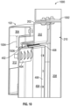
FIG. 10 illustrates a side cutaway view of an example supply cabinet, according to some aspects of the disclosure. As shown,cutaway view 1000 of supply cabinet ofFIG. 10 that is consistent withsupply cabinet 100 ofFIG. 1 includestop EMI barrier 1002 that is consistent withEMI barrier 702 ofFIG. 7 and is located at the top ofcabinet enclosure 210.Cutaway view 1000 also includesenclosure bracket 202 that is coupled toEMI barrier 1002. Also shown arecabinet door structure 102 and a finger bracket structure that is coupled tocabinet door structure 102. The finger bracket structure that includesfinger gasket structure 408 coupled tobracket 404 may be in contact withenclosure brackets 202 viafinger gaskets 402. Thecabinet door structure 102 includesouter border area 304 andinner border area 312. The finger bracket structure is coupled to top portion ofinner border area 312. Also shown inFIG. 10 are clearingdistance 1004 betweenouter border area 304 andbracket 404 of the finger bracket structure as well as escape gap 1006 between thebracket 404 andenclosure bracket 202. In some examples,FIG. 10 is a close-up view, at top portion, ofFIG. 7 . -
FIG. 11 illustrates a flow diagram of an example process of sealing a supply cabinet, according to some aspects of the disclosure. Notably, one or more steps ofprocess 1100 described herein may be omitted, performed in a different sequence, and/or combined with other processes for various types of applications contemplated herein.Process 1100 can be performed to sealsupply cabinets FIGS. 1 and2 . - The
process 1100 begins atstep 1102; a door structure is mounted over an opening of the cabinet enclosure. The door structure comprises a body having a first interface and a second interface. As shown inFIG. 2 ,cabinet door structure 102 is mounted overcabinet enclosure 210. In some examples, the cabinet enclosure is an EMI shielded cabinet enclosure andcabinet door structure 102 includes an EMI shielded body.Cabinet door structure 102 may include a first surface and the second surface opposite to the first surface. - In
step 1104, the first surface is faced to the inside ofcabinet enclosure 210 whencabinet door structure 102 closes. As shown inFIG. 2 ,door structure 102 has a first surface that whencabinet door structure 102 closes faces inside ofcabinet enclosure 210 that may be an EMI shielded cabinet enclosure. - In
step 1106, one or more finger bracket structures are mounted to the first surface. Each finger bracket structure may comprise a bracket and one or more finger gaskets. As shown inFIG.3 ,finger bracket structures 302 are mounted toinside surface 300 ofcabinet door structure 102. As shown inFIG.4 , eachfinger bracket structure 302 includesbracket 404 and one ormore finger gaskets 402. In some examples, two ormore finger gaskets 402 are coupled to createfinger gasket structure 408. - In
step 1108, one or more enclosure brackets are mounted around an edge of the opening of thecabinet enclosure 210 that may be an EMI shielded cabinet enclosure. As shown inFIG. 2 ,enclosure brackets 202 are coupled to edges ofcabinet enclosure 210. In some embodiments,enclosure brackets 202 are coupled to a doorframe mounted around the edges ofcabinet enclosure 210. In some examples,enclosure bracket 202 may protrudeoutside cabinet enclosure 210. Also, as shown inFIG. 5 ,enclosure bracket 508 that is coupled to top-side portion 112 of doorframe and protrudes inside a clearing distance at the top portion ofinner border area 312. Additionally,enclosure brackets 512 that is coupled to the latch-side portion 108 of doorframe protrudes toclearing distance 506 at the latch-side portion ofinner border area 312. As shown inFIG. 5 ,enclosure bracket 508 that is coupled to top-side portion 112 of doorframe may protrude inside the clearing distance (not shown) at the top portion ofinner border area 312. Additionally,enclosure brackets 608 that is coupled to the hinge-side portion 110 of doorframe protrudes toclearing distance 610 at the hinge-side portion ofinner border area 312. - In
step 1110, one or more finger gaskets are caused to come into contact with one or more enclosure brackets when closing the door structure. As shown inFIG. 5 , by closing thecabinet door structure 102,enclosure bracket 512 comes into contact with one ormore finger gaskets 402, which creates an EMI shield at the latch-side portion 108 of doorframe between the doorframe andcabinet door structure 102. Additionally, finger gaskets 402 (not shown) offinger gasket structure 408 at the top portion ofinner border area 312 come into contact withenclosure bracket 508, which creates an EMI shield at top-side portion 112 of doorframe between the doorframe andcabinet door structure 102. As shown inFIG. 6 , by closingcabinet door structure 102,enclosure bracket 608 comes into contact with one ormore finger gaskets 402, which creates an EMI shield at the hinge-side portion 110 of doorframe between the doorframe andcabinet door structure 102. Similarly, an EMI shield may be created at bottom-side portion 114 of doorframe between the doorframe andcabinet door structure 102. - In
step 1112, cabinet enclosure is sealed by closing the door structure. As described,cabinet enclosure 210 may be EMI shielded. Additionally, a body ofcabinet door structure 102 may also be EMI shielded. In some examples, there may be small openings betweencabinet door structure 102 and one or more of hinge-side portion 1 10 of the doorframe, top-side portion 112 of doorframe, bottom-side portion 114 of doorframe, and latch-side portion 18 of doorframe. Thus, RF signals may pass through the openings betweencabinet door structure 102 and one or more portions of doorframe and as a result,cabinet enclosure 210 may not be EMI shielded, e.g., may not be sealed from RF signals. As described above, by closingcabinet door structure 102 overcabinet enclosure 210,finger gaskets 402 come into contact withenclosure branch 202 at hinge-side portion 110, top-side portion 112, bottom-side portion 114, and latch-side portion 108 of the doorframe. Thus, the supply cabinet becomes EMI shielded. - The present disclosure is provided to enable any person skilled in the art to practice the various aspects described herein. The disclosure provides various examples of the subject technology, and the subject technology is not limited to these examples. Various modifications to these aspects will be readily apparent to those skilled in the art, and the generic principles defined herein may be applied to other aspects.
- A reference to an element in the singular is not intended to mean "one and only one" unless specifically so stated, but rather "one or more." Unless specifically stated otherwise, the term "some" refers to one or more. Pronouns in the masculine (e.g., his) include the feminine and neuter gender (e.g., her and its) and vice versa. Headings and subheadings, if any, are used for convenience only and do not limit the invention.
- The word "exemplary" is used herein to mean "serving as an example or illustration." Any aspect or design described herein as "exemplary" is not necessarily to be construed as preferred or advantageous over other aspects or designs. In one aspect, various alternative configurations and operations described herein may be considered to be at least equivalent.
- As used herein, the phrase "at least one of" preceding a series of items, with the term "or" to separate any of the items, modifies the list as a whole, rather than each item of the list. The phrase "at least one of" does not require selection of at least one item; rather, the phrase allows a meaning that includes at least one of any one of the items, and/or at least one of any combination of the items, and/or at least one of each of the items. By way of example, the phrase "at least one of A, B, or C" may refer to: only A, only B, or only C; or any combination of A, B, and C.
- A phrase such as an "aspect" does not imply that such aspect is essential to the subject technology or that such aspect applies to all configurations of the subject technology. A disclosure relating to an aspect may apply to all configurations, or one or more configurations. An aspect may provide one or more examples. A phrase such as an aspect may refer to one or more aspects and vice versa. A phrase such as an "embodiment" does not imply that such embodiment is essential to the subject technology or that such embodiment applies to all configurations of the subject technology. A disclosure relating to an embodiment may apply to all embodiments, or one or more embodiments. An embodiment may provide one or more examples. A phrase such an embodiment may refer to one or more embodiments and vice versa. A phrase such as a "configuration" does not imply that such configuration is essential to die subject technology or that such configuration applies to all configurations of the subject technology. A disclosure relating to a configuration may apply to all configurations, or one or more configurations. A configuration may provide one or more examples. A phrase such a configuration may refer to one or more configurations and vice versa.
- In one aspect, unless otherwise stated, all measurements, values, ratings, positions, magnitudes, sizes, and other specifications that are set forth in this specification, including in the claims that follow, are approximate, not exact. In one aspect, they are intended to have a reasonable range that is consistent with the functions to which they relate and with what is customary in the art to which they pertain.
- It is understood that the specific order or hierarchy of steps, operations or processes disclosed is an illustration of exemplary approaches. Based upon design preferences, it is understood that the specific order or hierarchy of steps, operations or processes may be rearranged. Some of the steps, operations or processes may be performed simultaneously. Some or all of the steps, operations, or processes may be performed automatically, without the intervention of a user. The accompanying method claims, if any, present elements of the various steps, operations or processes in a sample order, and are not meant to be limited to the specific order or hierarchy presented.
Claims (15)
- A door assembly comprising:a door structure (102) configured to be mounted over an opening of an enclosure (210), the door structure (102) comprising:a body comprising a first surface and a second surface opposite to the first surface, wherein the first surface is configured to face an inside of the enclosure (210) when the door structure (102) is closed;one or more finger bracketstructures (302) mounted on the first surface,wherein each one of the one or more finger bracket structures (302) comprises a bracket (404) and one or more finger gaskets (402) coupled to the bracket;a doorframe mounted around an edge of the opening of the enclosure (210), the doorframe comprising a top-side (112), a bottom-side (114), a hinge-side (110), and a latch-side (108), wherein one or more enclosure brackets (202) are coupled to one or more sides of the doorframe, wherein the one or more finger gaskets (402) of the one or more finger bracket structures (302) are configured to contact one or more enclosure brackets mounted around the edge of the opening of the enclosure (210) when the door structure (102) is closed, and wherein a combination of the one or more finger gaskets (402) in contact with the one or more enclosure brackets is configured to create an electromagnetic interference EMI shield at the edge of the opening of the enclosure (210); anda radio frequency RF fence bracket (504) parallel to the latch-side (108) and coupled to the latch-side (108) of the doorframe, wherein the RF fence bracket (504) is configured to create a narrow path between the doorframe and the door structure (102), and wherein the narrow path is configured to attenuate RF signals passing through the narrow path and shield the edge of the opening of the enclosure (210).
- The door assembly of claim 1, further comprising an EMI shielded gasket (606) parallel to the hinge-side (110) and coupled between the hinge-side (110) of the doorframe and the door structure (102), wherein the EMI shielded gasket (606) is made of fabric over foam, and wherein the EMI shielded gasket (606) is configured to shield the edge of the opening of the enclosure (210).
- The door assembly of claim 1, further comprising:
an RF transceiver inside the enclosure (210), wherein the RF transceiver is configured to transmit an RF signal to detect RFID tags inside the enclosure (210). - The door assembly of claim 1, wherein the body of door structure (102) includes an EMI shielded clear window (104).
- The door assembly of claim 1, wherein the first surface of the door structure (102) includes an outer border area (304) and an inner recessed area (312) surrounded by the outer border area (304), wherein the outer border area (304) extends from the inner recessed area (312) to an edge of the door structure (102), wherein the finger bracket structures (302) are mounted inside the inner recessed area (312) next to the outer border area (304) with a clearing distance (306) of a predefined width between the finger bracket structures (302) and the outer border area (304);wherein the one or more enclosure brackets protrude outside the edge of the opening of the enclosure (210) and when the door structure (102) is closed the one or more enclosure brackets extend into the clearing distance (306) between the finger bracket structures (302) and the outer border area (304); andwherein the one or more finger gaskets (402) of the one or more finger bracket structures (302) are configured to contact the one or more enclosure brackets in the clearing distance (306) between the finger bracket structures (302) and the outer border area (304) to shield the edge of the opening of the enclosure (210).
- The door assembly of claim 1, wherein the one or more finger gaskets (402) of the one or more finger bracket structures (302) are made from Beryllium Copper and are Electroless Nickel plated.
- The door assembly of claim 1, wherein the enclosure (210) is EMI shielded, and wherein the body of the door structure (102) is EMI shielded.
- A method (1100) of sealing radio frequency RF signals inside an electromagnetic interference EMI shielded cabinet enclosure (210), the method (1100) comprising:configuring a door structure (102) to be mounted over an opening of the EMI shielded cabinet enclosure (210), wherein the door structure (102) comprises an EMI shielded body having a first surface and a second surface opposite to the first surface;facing the first surface to an inside of the EMI shielded cabinet enclosure (210) when the door structure (102) closes;mounting one or more finger bracket structures (302) to the first surface, wherein each one of the one or more finger bracket structures (302) comprises a bracket (404) and one or more finger gaskets (402) coupled to the bracket;mounting one or more enclosure brackets (202) around an edge of the opening of the EMI shielded cabinet enclosure (210);mounting a doorframe around the edge of the opening of the EMI shielded cabinet enclosure (210), wherein the doorframe comprising a top-side (112), a bottom-side (114), a hinge-side (110), and a latch-side (108);mounting, the one or more enclosure brackets to one or more sides of the doorframe;mounting an RF fence bracket (504) parallel to the latch-side (108) of the doorframe and parallel to the latch-side (108) of the doorframe, wherein the RF fence bracket (504) is made of an EMI shielded material;creating a narrow path between the doorframe and the door structure (102) to attenuate RF signals passing through the narrow path and shield the edge of the opening of the EMI shielded cabinet enclosure (210);causing the one or more finger gaskets (402) of the one or more finger bracket structures (302) to contact the one or more enclosure brackets when closing the door structure (102); andsealing the EMI shielded cabinet enclosure (210) by closing the door structure (102).
- The method (1100) of claim 8, wherein an RF transceiver is mounted inside the EMI shielded cabinet enclosure (210), wherein the RF transceiver is configured to transmit an RF signal to detect RFID tags inside the EMI shielded cabinet enclosure (210), and wherein closing the door structure (102) shields the edge of the opening of the EMI shielded cabinet enclosure (210) against a leakage of RF signals to and/or from an outside of the EMI shielded cabinet enclosure (210).
- The method (1100) of claim 8, further comprising:
mounting an EMI shielded gasket (606) parallel to the hinge-side (110) of the doorframe, wherein the EMI shielded gasket (606) is coupled between the hinge-side (110) of the doorframe and the door structure, wherein the EMI shielded gasket (606) is made of fabric over foam to close an RF opening between the hinge-side (110) of the doorframe and the door structure (102) to reduce an RF leakage, and wherein the EMI shielded gasket (606) is configured to shield the edge of the opening of the EMI shielded cabinet enclosure (210). - The method (1100) of claim 8, wherein the EMI shielded body of the door structure (102) includes an EMI shielded clear window (104).
- The method (1100) of claim 8, wherein the one or more finger gaskets (402) of the one or more finger bracket structures (302) are made from Beryllium Copper and are Electroless Nickel plated.
- The method (1100) of claim 8, wherein the first surface of the door structure (102) includes an outer border area (304) and an inner recessed area (312) surrounded by the outer border area (304), wherein the outer border area (304) extends from the inner recessed area (312) to an edge of the door structure (102), wherein the method (1100) further comprises:mounting the one or more finger bracket structures (302) inside the inner recessed area (312) next to the outer border area (304); andproviding a clearing distance (306) of a predefined width between the finger bracket structures (302) and the outer border area (304).
- The method (1100) of claim 13, further comprising:arranging the one or more enclosure brackets to protrude outside the edge of the opening of the EMI shielded cabinet enclosure (210); andextending the one or more enclosure brackets into the clearing distance (306) between the finger bracket structures (302) and the outer border area (304) when the door structure (102) closes.
- The method (1100) of claim 14, further comprising:
configuring the one or more finger gaskets (402) of the one or more finger bracket structures (302) to contact the one or more enclosure brackets in the clearing distance (306) between the finger bracket structures (302) and the outer border area (304) to shield the edge of the opening of the EMI shielded cabinet enclosure (210).
Applications Claiming Priority (2)
| Application Number | Priority Date | Filing Date | Title |
|---|---|---|---|
| US15/977,758 US10420258B1 (en) | 2018-05-11 | 2018-05-11 | Supply station with door shield |
| PCT/US2019/030378 WO2019217195A1 (en) | 2018-05-11 | 2019-05-02 | Supply station with door shield |
Publications (3)
| Publication Number | Publication Date |
|---|---|
| EP3791702A1 EP3791702A1 (en) | 2021-03-17 |
| EP3791702C0 EP3791702C0 (en) | 2023-08-30 |
| EP3791702B1 true EP3791702B1 (en) | 2023-08-30 |
Family
ID=66530539
Family Applications (1)
| Application Number | Title | Priority Date | Filing Date |
|---|---|---|---|
| EP19724031.0A Active EP3791702B1 (en) | 2018-05-11 | 2019-05-02 | Supply station with door shield |
Country Status (6)
| Country | Link |
|---|---|
| US (4) | US10420258B1 (en) |
| EP (1) | EP3791702B1 (en) |
| CN (1) | CN112106456B (en) |
| CA (1) | CA3098142C (en) |
| ES (1) | ES2964392T3 (en) |
| WO (1) | WO2019217195A1 (en) |
Families Citing this family (16)
| Publication number | Priority date | Publication date | Assignee | Title |
|---|---|---|---|---|
| US10420258B1 (en) | 2018-05-11 | 2019-09-17 | Carefusion 303, Inc. | Supply station with door shield |
| US11647614B2 (en) * | 2019-06-18 | 2023-05-09 | John Latuperissa | Portable data center and server rack system with integrated electromagnetic pulse protection |
| US10869415B1 (en) | 2019-07-19 | 2020-12-15 | Dell Products L.P. | System and method for operating electromagnetically isolated device |
| US11378608B2 (en) | 2019-07-19 | 2022-07-05 | Dell Products L.P. | System and method for device state determination |
| US12004336B2 (en) | 2019-07-19 | 2024-06-04 | Dell Products L.P. | System and method for thermal management and electromagnetic interference management |
| US11143682B2 (en) | 2019-07-19 | 2021-10-12 | Dell Products L.P. | System and method for communicating externally from an electromagnetic interference suppressed volume |
| US11122718B2 (en) | 2019-07-19 | 2021-09-14 | Dell Products L.P. | System and method for device level electromagnetic interference management |
| US11132038B2 (en) | 2019-07-19 | 2021-09-28 | Dell Products L.P. | System and method for thermal management of shadowed devices |
| US11129307B2 (en) | 2019-07-19 | 2021-09-21 | Dell Products L.P. | System and method for managing thermal states of devices |
| US10917996B1 (en) | 2019-07-19 | 2021-02-09 | Dell Products L.P. | System and method for device level thermal management and electromagnetic interference management |
| US11234347B2 (en) | 2019-07-19 | 2022-01-25 | Dell Products L.P. | System and method for physical management of devices |
| US11644425B2 (en) | 2019-07-19 | 2023-05-09 | Dell Products L.P. | System and method for optical state determination |
| US10980159B2 (en) | 2019-07-19 | 2021-04-13 | Dell Products L.P. | System and method for managing multiple connections |
| US11399450B2 (en) | 2019-07-19 | 2022-07-26 | Dell Products L.P. | System and method for managing electromagnetic interference |
| US11234350B2 (en) * | 2019-08-21 | 2022-01-25 | Dell Products L.P. | System and method for isolated device access |
| US11147194B2 (en) * | 2019-08-21 | 2021-10-12 | Dell Products L.P. | System and method for managing electromagnetic interference |
Family Cites Families (21)
| Publication number | Priority date | Publication date | Assignee | Title |
|---|---|---|---|---|
| US4677251A (en) * | 1984-01-16 | 1987-06-30 | Merewether David E | Voltage dividing shielded door seal |
| GB2183920A (en) | 1985-11-27 | 1987-06-10 | Morgan Marine Limited | Electromagnetic door seal |
| DE8716599U1 (en) * | 1987-12-16 | 1988-03-31 | Zeppelin-Metallwerke Gmbh, 7990 Friedrichshafen | Electromagnetically shielded cabin with a sealing system |
| US5004866A (en) * | 1989-10-27 | 1991-04-02 | International Business Machines Corp. | Self-contained grounding strip |
| US5029254A (en) * | 1990-03-23 | 1991-07-02 | Instrument Specialties Company, Inc. | Clip mounted electromagnetic shielding device |
| DE4102019C1 (en) * | 1991-01-24 | 1992-07-09 | Schroff Gmbh, 7541 Straubenhardt, De | |
| US5223670A (en) * | 1991-12-02 | 1993-06-29 | Her Majesty The Queen In Right Of Canada | Hinged door assembly |
| DE29521087U1 (en) * | 1995-10-28 | 1996-09-19 | Rittal-Werk Rudolf Loh GmbH & Co. KG, 35745 Herborn | HF-tight control cabinet |
| DE19614692C1 (en) | 1996-04-13 | 1997-06-05 | Schroff Gmbh | Electronics cabinet |
| GB2331404B (en) * | 1997-11-12 | 2002-05-22 | Vero Electronics Ltd | Electrical contacts for housings |
| US6303854B1 (en) * | 1999-07-22 | 2001-10-16 | Marconi Communications, Inc. | EMI shielded telecommunications enclosure |
| US6483023B1 (en) * | 2000-01-04 | 2002-11-19 | Fujitsu Network Communications, Inc. | Fabric wrapped over spring EMI gasket |
| US8289717B2 (en) * | 2007-07-19 | 2012-10-16 | Qwest Communications International Inc. | Protective telecommunications enclosure systems and methods |
| US7889515B2 (en) * | 2008-02-15 | 2011-02-15 | Laird Technologies, Inc. | EMI shielding assemblies and related methods of retaining components thereof together |
| CN102802386B (en) * | 2011-05-25 | 2016-04-20 | 莱尔德电子材料(深圳)有限公司 | Electromagnetic interference shield assembly |
| US8770479B1 (en) | 2013-01-11 | 2014-07-08 | S&S X-Ray Products, Inc. | Medical storage cabinet with RFID inventory |
| US20140216806A1 (en) * | 2013-02-07 | 2014-08-07 | Laird Technologies, Inc | Emi gaskets with perforations |
| US10117365B2 (en) | 2015-12-30 | 2018-10-30 | Meps Real-Time, Inc. | Shielded enclosure having tortuous path seal |
| EP3504882A4 (en) * | 2016-08-24 | 2020-04-01 | Commscope Technologies LLC | Electronic equipment cabinets having radio frequency relays |
| CN207097134U (en) | 2017-06-05 | 2018-03-13 | 安徽原力知觉科技有限公司 | A kind of medical goods and materials intelligent storage cabinet based on RFID technique |
| US10420258B1 (en) * | 2018-05-11 | 2019-09-17 | Carefusion 303, Inc. | Supply station with door shield |
-
2018
- 2018-05-11 US US15/977,758 patent/US10420258B1/en active Active
-
2019
- 2019-05-02 WO PCT/US2019/030378 patent/WO2019217195A1/en not_active Ceased
- 2019-05-02 CA CA3098142A patent/CA3098142C/en active Active
- 2019-05-02 CN CN201980031489.XA patent/CN112106456B/en active Active
- 2019-05-02 EP EP19724031.0A patent/EP3791702B1/en active Active
- 2019-05-02 ES ES19724031T patent/ES2964392T3/en active Active
- 2019-08-09 US US16/536,394 patent/US10785899B2/en active Active
-
2020
- 2020-08-12 US US16/991,654 patent/US11304345B2/en active Active
-
2022
- 2022-03-04 US US17/687,165 patent/US11602088B2/en active Active
Also Published As
| Publication number | Publication date |
|---|---|
| US10420258B1 (en) | 2019-09-17 |
| US10785899B2 (en) | 2020-09-22 |
| EP3791702A1 (en) | 2021-03-17 |
| CA3098142C (en) | 2024-06-18 |
| CA3098142A1 (en) | 2019-11-14 |
| ES2964392T3 (en) | 2024-04-05 |
| EP3791702C0 (en) | 2023-08-30 |
| US11602088B2 (en) | 2023-03-07 |
| CN112106456B (en) | 2023-06-13 |
| US20220192063A1 (en) | 2022-06-16 |
| WO2019217195A1 (en) | 2019-11-14 |
| US20200375072A1 (en) | 2020-11-26 |
| CN112106456A (en) | 2020-12-18 |
| US11304345B2 (en) | 2022-04-12 |
| US20190364701A1 (en) | 2019-11-28 |
Similar Documents
| Publication | Publication Date | Title |
|---|---|---|
| US11602088B2 (en) | Supply station with door shield | |
| US10724784B2 (en) | Household appliance | |
| US7053348B1 (en) | Microwave oven | |
| US4820885A (en) | Magnetic gasket for shielding against electromagnetic radiation | |
| CN205536761U (en) | Refrigerated commercial cabinet | |
| CA3009513A1 (en) | Shielded enclosure having tortuous path seal | |
| US4760214A (en) | Contacting arrangement for shielded compartments and spaces with HF-tight shielded, movable and abutting housing components | |
| US4577079A (en) | Door of microwave oven | |
| KR101478552B1 (en) | Door for EMP shielding | |
| KR20100131572A (en) | Shielding device of door for Selterbox | |
| US5691503A (en) | Electro-magnetically shielded door hinge | |
| US7275770B2 (en) | Interlock system for enclosures | |
| KR101602040B1 (en) | Electromagnetic waves and electromagnetic shielded enclosure structure | |
| CN108235674A (en) | sales counter | |
| US7425026B1 (en) | Seismic-resistant equipment cabinets and door latches | |
| CN108901195B (en) | Shielding door and construction method thereof | |
| CN216124067U (en) | Intelligent cabinet with shielding function | |
| CN208384685U (en) | A kind of Vending Machine has the doorframe of signal shielding function | |
| PL247189B1 (en) | Radio wave shield and shielded container | |
| WO2020120368A1 (en) | Refrigerator | |
| AU2025226841B1 (en) | Electromagnetic seal secure door set | |
| JP6735153B2 (en) | Door frame structure for hinged doors | |
| CN205755261U (en) | Information equipment double storehouses clamshell doors electromagnetic shielding cabinet | |
| KR940008015Y1 (en) | Apparatus for shielding micro-wave of electronic range | |
| CN109511254A (en) | A kind of electromagnetic shielding box |
Legal Events
| Date | Code | Title | Description |
|---|---|---|---|
| STAA | Information on the status of an ep patent application or granted ep patent |
Free format text: STATUS: UNKNOWN |
|
| STAA | Information on the status of an ep patent application or granted ep patent |
Free format text: STATUS: THE INTERNATIONAL PUBLICATION HAS BEEN MADE |
|
| PUAI | Public reference made under article 153(3) epc to a published international application that has entered the european phase |
Free format text: ORIGINAL CODE: 0009012 |
|
| STAA | Information on the status of an ep patent application or granted ep patent |
Free format text: STATUS: REQUEST FOR EXAMINATION WAS MADE |
|
| 17P | Request for examination filed |
Effective date: 20201210 |
|
| AK | Designated contracting states |
Kind code of ref document: A1 Designated state(s): AL AT BE BG CH CY CZ DE DK EE ES FI FR GB GR HR HU IE IS IT LI LT LU LV MC MK MT NL NO PL PT RO RS SE SI SK SM TR |
|
| AX | Request for extension of the european patent |
Extension state: BA ME |
|
| DAV | Request for validation of the european patent (deleted) | ||
| DAX | Request for extension of the european patent (deleted) | ||
| GRAP | Despatch of communication of intention to grant a patent |
Free format text: ORIGINAL CODE: EPIDOSNIGR1 |
|
| STAA | Information on the status of an ep patent application or granted ep patent |
Free format text: STATUS: GRANT OF PATENT IS INTENDED |
|
| INTG | Intention to grant announced |
Effective date: 20230322 |
|
| GRAS | Grant fee paid |
Free format text: ORIGINAL CODE: EPIDOSNIGR3 |
|
| GRAA | (expected) grant |
Free format text: ORIGINAL CODE: 0009210 |
|
| STAA | Information on the status of an ep patent application or granted ep patent |
Free format text: STATUS: THE PATENT HAS BEEN GRANTED |
|
| AK | Designated contracting states |
Kind code of ref document: B1 Designated state(s): AL AT BE BG CH CY CZ DE DK EE ES FI FR GB GR HR HU IE IS IT LI LT LU LV MC MK MT NL NO PL PT RO RS SE SI SK SM TR |
|
| REG | Reference to a national code |
Ref country code: GB Ref legal event code: FG4D |
|
| REG | Reference to a national code |
Ref country code: CH Ref legal event code: EP |
|
| REG | Reference to a national code |
Ref country code: DE Ref legal event code: R096 Ref document number: 602019036118 Country of ref document: DE |
|
| REG | Reference to a national code |
Ref country code: IE Ref legal event code: FG4D |
|
| U01 | Request for unitary effect filed |
Effective date: 20230927 |
|
| U07 | Unitary effect registered |
Designated state(s): AT BE BG DE DK EE FI FR IT LT LU LV MT NL PT SE SI Effective date: 20231004 |
|
| PG25 | Lapsed in a contracting state [announced via postgrant information from national office to epo] |
Ref country code: GR Free format text: LAPSE BECAUSE OF FAILURE TO SUBMIT A TRANSLATION OF THE DESCRIPTION OR TO PAY THE FEE WITHIN THE PRESCRIBED TIME-LIMIT Effective date: 20231201 |
|
| PG25 | Lapsed in a contracting state [announced via postgrant information from national office to epo] |
Ref country code: IS Free format text: LAPSE BECAUSE OF FAILURE TO SUBMIT A TRANSLATION OF THE DESCRIPTION OR TO PAY THE FEE WITHIN THE PRESCRIBED TIME-LIMIT Effective date: 20231230 |
|
| PG25 | Lapsed in a contracting state [announced via postgrant information from national office to epo] |
Ref country code: RS Free format text: LAPSE BECAUSE OF FAILURE TO SUBMIT A TRANSLATION OF THE DESCRIPTION OR TO PAY THE FEE WITHIN THE PRESCRIBED TIME-LIMIT Effective date: 20230830 Ref country code: NO Free format text: LAPSE BECAUSE OF FAILURE TO SUBMIT A TRANSLATION OF THE DESCRIPTION OR TO PAY THE FEE WITHIN THE PRESCRIBED TIME-LIMIT Effective date: 20231130 Ref country code: IS Free format text: LAPSE BECAUSE OF FAILURE TO SUBMIT A TRANSLATION OF THE DESCRIPTION OR TO PAY THE FEE WITHIN THE PRESCRIBED TIME-LIMIT Effective date: 20231230 Ref country code: HR Free format text: LAPSE BECAUSE OF FAILURE TO SUBMIT A TRANSLATION OF THE DESCRIPTION OR TO PAY THE FEE WITHIN THE PRESCRIBED TIME-LIMIT Effective date: 20230830 Ref country code: GR Free format text: LAPSE BECAUSE OF FAILURE TO SUBMIT A TRANSLATION OF THE DESCRIPTION OR TO PAY THE FEE WITHIN THE PRESCRIBED TIME-LIMIT Effective date: 20231201 |
|
| PG25 | Lapsed in a contracting state [announced via postgrant information from national office to epo] |
Ref country code: PL Free format text: LAPSE BECAUSE OF FAILURE TO SUBMIT A TRANSLATION OF THE DESCRIPTION OR TO PAY THE FEE WITHIN THE PRESCRIBED TIME-LIMIT Effective date: 20230830 |
|
| REG | Reference to a national code |
Ref country code: ES Ref legal event code: FG2A Ref document number: 2964392 Country of ref document: ES Kind code of ref document: T3 Effective date: 20240405 |
|
| PG25 | Lapsed in a contracting state [announced via postgrant information from national office to epo] |
Ref country code: SM Free format text: LAPSE BECAUSE OF FAILURE TO SUBMIT A TRANSLATION OF THE DESCRIPTION OR TO PAY THE FEE WITHIN THE PRESCRIBED TIME-LIMIT Effective date: 20230830 Ref country code: RO Free format text: LAPSE BECAUSE OF FAILURE TO SUBMIT A TRANSLATION OF THE DESCRIPTION OR TO PAY THE FEE WITHIN THE PRESCRIBED TIME-LIMIT Effective date: 20230830 Ref country code: CZ Free format text: LAPSE BECAUSE OF FAILURE TO SUBMIT A TRANSLATION OF THE DESCRIPTION OR TO PAY THE FEE WITHIN THE PRESCRIBED TIME-LIMIT Effective date: 20230830 Ref country code: SK Free format text: LAPSE BECAUSE OF FAILURE TO SUBMIT A TRANSLATION OF THE DESCRIPTION OR TO PAY THE FEE WITHIN THE PRESCRIBED TIME-LIMIT Effective date: 20230830 |
|
| U20 | Renewal fee for the european patent with unitary effect paid |
Year of fee payment: 6 Effective date: 20240418 |
|
| REG | Reference to a national code |
Ref country code: DE Ref legal event code: R097 Ref document number: 602019036118 Country of ref document: DE |
|
| PLBE | No opposition filed within time limit |
Free format text: ORIGINAL CODE: 0009261 |
|
| STAA | Information on the status of an ep patent application or granted ep patent |
Free format text: STATUS: NO OPPOSITION FILED WITHIN TIME LIMIT |
|
| 26N | No opposition filed |
Effective date: 20240603 |
|
| REG | Reference to a national code |
Ref country code: CH Ref legal event code: PL |
|
| PG25 | Lapsed in a contracting state [announced via postgrant information from national office to epo] |
Ref country code: MC Free format text: LAPSE BECAUSE OF FAILURE TO SUBMIT A TRANSLATION OF THE DESCRIPTION OR TO PAY THE FEE WITHIN THE PRESCRIBED TIME-LIMIT Effective date: 20230830 |
|
| PG25 | Lapsed in a contracting state [announced via postgrant information from national office to epo] |
Ref country code: MC Free format text: LAPSE BECAUSE OF FAILURE TO SUBMIT A TRANSLATION OF THE DESCRIPTION OR TO PAY THE FEE WITHIN THE PRESCRIBED TIME-LIMIT Effective date: 20230830 Ref country code: CH Free format text: LAPSE BECAUSE OF NON-PAYMENT OF DUE FEES Effective date: 20240531 |
|
| PG25 | Lapsed in a contracting state [announced via postgrant information from national office to epo] |
Ref country code: IE Free format text: LAPSE BECAUSE OF NON-PAYMENT OF DUE FEES Effective date: 20240502 |
|
| U20 | Renewal fee for the european patent with unitary effect paid |
Year of fee payment: 7 Effective date: 20250423 |
|
| PG25 | Lapsed in a contracting state [announced via postgrant information from national office to epo] |
Ref country code: CY Free format text: LAPSE BECAUSE OF FAILURE TO SUBMIT A TRANSLATION OF THE DESCRIPTION OR TO PAY THE FEE WITHIN THE PRESCRIBED TIME-LIMIT; INVALID AB INITIO Effective date: 20190502 |
|
| PG25 | Lapsed in a contracting state [announced via postgrant information from national office to epo] |
Ref country code: HU Free format text: LAPSE BECAUSE OF FAILURE TO SUBMIT A TRANSLATION OF THE DESCRIPTION OR TO PAY THE FEE WITHIN THE PRESCRIBED TIME-LIMIT; INVALID AB INITIO Effective date: 20190502 |
|
| U20 | Renewal fee for the european patent with unitary effect paid |
Year of fee payment: 8 Effective date: 20260421 |
|
| PG25 | Lapsed in a contracting state [announced via postgrant information from national office to epo] |
Ref country code: TR Free format text: LAPSE BECAUSE OF FAILURE TO SUBMIT A TRANSLATION OF THE DESCRIPTION OR TO PAY THE FEE WITHIN THE PRESCRIBED TIME-LIMIT Effective date: 20230830 |
|
| PGFP | Annual fee paid to national office [announced via postgrant information from national office to epo] |
Ref country code: ES Payment date: 20260601 Year of fee payment: 8 |
|
| PGFP | Annual fee paid to national office [announced via postgrant information from national office to epo] |
Ref country code: GB Payment date: 20260421 Year of fee payment: 8 |