EP3791451B1 - Tunable vcsel polarization control through dissimilar die bonding - Google Patents
Tunable vcsel polarization control through dissimilar die bonding Download PDFInfo
- Publication number
- EP3791451B1 EP3791451B1 EP19726272.8A EP19726272A EP3791451B1 EP 3791451 B1 EP3791451 B1 EP 3791451B1 EP 19726272 A EP19726272 A EP 19726272A EP 3791451 B1 EP3791451 B1 EP 3791451B1
- Authority
- EP
- European Patent Office
- Prior art keywords
- membrane
- vcsel
- mirror
- membrane device
- bonding
- Prior art date
- Legal status (The legal status is an assumption and is not a legal conclusion. Google has not performed a legal analysis and makes no representation as to the accuracy of the status listed.)
- Active
Links
Images

Classifications
-
- H—ELECTRICITY
- H01—ELECTRIC ELEMENTS
- H01S—DEVICES USING THE PROCESS OF LIGHT AMPLIFICATION BY STIMULATED EMISSION OF RADIATION [LASER] TO AMPLIFY OR GENERATE LIGHT; DEVICES USING STIMULATED EMISSION OF ELECTROMAGNETIC RADIATION IN WAVE RANGES OTHER THAN OPTICAL
- H01S5/00—Semiconductor lasers
- H01S5/30—Structure or shape of the active region; Materials used for the active region
- H01S5/34—Structure or shape of the active region; Materials used for the active region comprising quantum well or superlattice structures, e.g. single quantum well [SQW] lasers, multiple quantum well [MQW] lasers or graded index separate confinement heterostructure [GRINSCH] lasers
- H01S5/3403—Structure or shape of the active region; Materials used for the active region comprising quantum well or superlattice structures, e.g. single quantum well [SQW] lasers, multiple quantum well [MQW] lasers or graded index separate confinement heterostructure [GRINSCH] lasers having a strained layer structure in which the strain performs a special function, e.g. general strain effects, strain versus polarisation
- H01S5/3404—Structure or shape of the active region; Materials used for the active region comprising quantum well or superlattice structures, e.g. single quantum well [SQW] lasers, multiple quantum well [MQW] lasers or graded index separate confinement heterostructure [GRINSCH] lasers having a strained layer structure in which the strain performs a special function, e.g. general strain effects, strain versus polarisation influencing the polarisation
-
- H—ELECTRICITY
- H01—ELECTRIC ELEMENTS
- H01S—DEVICES USING THE PROCESS OF LIGHT AMPLIFICATION BY STIMULATED EMISSION OF RADIATION [LASER] TO AMPLIFY OR GENERATE LIGHT; DEVICES USING STIMULATED EMISSION OF ELECTROMAGNETIC RADIATION IN WAVE RANGES OTHER THAN OPTICAL
- H01S5/00—Semiconductor lasers
- H01S5/02—Structural details or components not essential to laser action
- H01S5/022—Mountings; Housings
- H01S5/023—Mount members, e.g. sub-mount members
- H01S5/02325—Mechanically integrated components on mount members or optical micro-benches
-
- H—ELECTRICITY
- H01—ELECTRIC ELEMENTS
- H01S—DEVICES USING THE PROCESS OF LIGHT AMPLIFICATION BY STIMULATED EMISSION OF RADIATION [LASER] TO AMPLIFY OR GENERATE LIGHT; DEVICES USING STIMULATED EMISSION OF ELECTROMAGNETIC RADIATION IN WAVE RANGES OTHER THAN OPTICAL
- H01S5/00—Semiconductor lasers
- H01S5/02—Structural details or components not essential to laser action
- H01S5/022—Mountings; Housings
- H01S5/0233—Mounting configuration of laser chips
- H01S5/02345—Wire-bonding
-
- H—ELECTRICITY
- H01—ELECTRIC ELEMENTS
- H01S—DEVICES USING THE PROCESS OF LIGHT AMPLIFICATION BY STIMULATED EMISSION OF RADIATION [LASER] TO AMPLIFY OR GENERATE LIGHT; DEVICES USING STIMULATED EMISSION OF ELECTROMAGNETIC RADIATION IN WAVE RANGES OTHER THAN OPTICAL
- H01S5/00—Semiconductor lasers
- H01S5/06—Arrangements for controlling the laser output parameters, e.g. by operating on the active medium
- H01S5/0607—Arrangements for controlling the laser output parameters, e.g. by operating on the active medium by varying physical parameters other than the potential of the electrodes, e.g. by an electric or magnetic field, mechanical deformation, pressure, light, temperature
-
- H—ELECTRICITY
- H01—ELECTRIC ELEMENTS
- H01S—DEVICES USING THE PROCESS OF LIGHT AMPLIFICATION BY STIMULATED EMISSION OF RADIATION [LASER] TO AMPLIFY OR GENERATE LIGHT; DEVICES USING STIMULATED EMISSION OF ELECTROMAGNETIC RADIATION IN WAVE RANGES OTHER THAN OPTICAL
- H01S5/00—Semiconductor lasers
- H01S5/10—Construction or shape of the optical resonator, e.g. extended or external cavity, coupled cavities, bent-guide, varying width, thickness or composition of the active region
- H01S5/18—Surface-emitting [SE] lasers, e.g. having both horizontal and vertical cavities
- H01S5/183—Surface-emitting [SE] lasers, e.g. having both horizontal and vertical cavities having only vertical cavities, e.g. vertical cavity surface-emitting lasers [VCSEL]
- H01S5/18355—Surface-emitting [SE] lasers, e.g. having both horizontal and vertical cavities having only vertical cavities, e.g. vertical cavity surface-emitting lasers [VCSEL] having a defined polarisation
-
- H—ELECTRICITY
- H01—ELECTRIC ELEMENTS
- H01S—DEVICES USING THE PROCESS OF LIGHT AMPLIFICATION BY STIMULATED EMISSION OF RADIATION [LASER] TO AMPLIFY OR GENERATE LIGHT; DEVICES USING STIMULATED EMISSION OF ELECTROMAGNETIC RADIATION IN WAVE RANGES OTHER THAN OPTICAL
- H01S5/00—Semiconductor lasers
- H01S5/10—Construction or shape of the optical resonator, e.g. extended or external cavity, coupled cavities, bent-guide, varying width, thickness or composition of the active region
- H01S5/18—Surface-emitting [SE] lasers, e.g. having both horizontal and vertical cavities
- H01S5/183—Surface-emitting [SE] lasers, e.g. having both horizontal and vertical cavities having only vertical cavities, e.g. vertical cavity surface-emitting lasers [VCSEL]
- H01S5/18361—Structure of the reflectors, e.g. hybrid mirrors
- H01S5/18363—Structure of the reflectors, e.g. hybrid mirrors comprising air layers
- H01S5/18366—Membrane DBR, i.e. a movable DBR on top of the VCSEL
-
- H—ELECTRICITY
- H01—ELECTRIC ELEMENTS
- H01S—DEVICES USING THE PROCESS OF LIGHT AMPLIFICATION BY STIMULATED EMISSION OF RADIATION [LASER] TO AMPLIFY OR GENERATE LIGHT; DEVICES USING STIMULATED EMISSION OF ELECTROMAGNETIC RADIATION IN WAVE RANGES OTHER THAN OPTICAL
- H01S5/00—Semiconductor lasers
- H01S5/10—Construction or shape of the optical resonator, e.g. extended or external cavity, coupled cavities, bent-guide, varying width, thickness or composition of the active region
- H01S5/18—Surface-emitting [SE] lasers, e.g. having both horizontal and vertical cavities
- H01S5/183—Surface-emitting [SE] lasers, e.g. having both horizontal and vertical cavities having only vertical cavities, e.g. vertical cavity surface-emitting lasers [VCSEL]
- H01S5/18361—Structure of the reflectors, e.g. hybrid mirrors
- H01S5/1838—Reflector bonded by wafer fusion or by an intermediate compound
-
- H—ELECTRICITY
- H01—ELECTRIC ELEMENTS
- H01S—DEVICES USING THE PROCESS OF LIGHT AMPLIFICATION BY STIMULATED EMISSION OF RADIATION [LASER] TO AMPLIFY OR GENERATE LIGHT; DEVICES USING STIMULATED EMISSION OF ELECTROMAGNETIC RADIATION IN WAVE RANGES OTHER THAN OPTICAL
- H01S5/00—Semiconductor lasers
- H01S5/30—Structure or shape of the active region; Materials used for the active region
- H01S5/32—Structure or shape of the active region; Materials used for the active region comprising PN junctions, e.g. hetero- or double- heterostructures
- H01S5/3201—Structure or shape of the active region; Materials used for the active region comprising PN junctions, e.g. hetero- or double- heterostructures incorporating bulkstrain effects, e.g. strain compensation, strain related to polarisation
-
- H—ELECTRICITY
- H01—ELECTRIC ELEMENTS
- H01S—DEVICES USING THE PROCESS OF LIGHT AMPLIFICATION BY STIMULATED EMISSION OF RADIATION [LASER] TO AMPLIFY OR GENERATE LIGHT; DEVICES USING STIMULATED EMISSION OF ELECTROMAGNETIC RADIATION IN WAVE RANGES OTHER THAN OPTICAL
- H01S5/00—Semiconductor lasers
- H01S5/30—Structure or shape of the active region; Materials used for the active region
- H01S5/34—Structure or shape of the active region; Materials used for the active region comprising quantum well or superlattice structures, e.g. single quantum well [SQW] lasers, multiple quantum well [MQW] lasers or graded index separate confinement heterostructure [GRINSCH] lasers
- H01S5/343—Structure or shape of the active region; Materials used for the active region comprising quantum well or superlattice structures, e.g. single quantum well [SQW] lasers, multiple quantum well [MQW] lasers or graded index separate confinement heterostructure [GRINSCH] lasers in AIIIBV compounds, e.g. AlGaAs-laser, InP-based laser
Definitions
- VCSELs Vertical cavity surface emitting lasers
- This asymmetry can be provided by rectangular mesas [1], high contrast grating mirrors [2,3], subwavelength gratings [4], possible strain from oxidized DBR mirrors [5], asymmetric metal strain films applied to the crystal [6], asymmetric current apertures [8,9], surface gratings [10], growth on tilted crystal planes [11,12], externally induced asymmetric strain [13], polarization loss anisotropy [14], or asymmetric current injection [15].
- XP 011344224 describes wavelength modulation over 500 kHz by a micromechanically tunable vertical-cavity surface-emitting laser (VCSEL) consisting of an InP-based half-VCSEL chip and micromachined silicon-on-insulator chip with a concave movable mirror.
- VCSEL vertical-cavity surface-emitting laser
- the present invention concerns a design and method for introducing asymmetric crystal strain to control polarization in a tunable VCSEL, either optically or electrically pumped.
- the scope of protection is determined from the claims.
- the invention is especially relevant to wafer- or die- bonded tunable VCSELs. Examples of such devices are disclosed in United States Patent Application US20140176958A1, by Flanders, Kuznetsov, Atia, and Johnson , "OCT System with Bonded MEMS Tunable Mirror VCSEL Swept Source”.
- the invention features a vertical cavity surface emitting lasers (VCSEL), comprising a membrane device and a half VCSEL device. Then, mechanical stress is applied to the half VCSEL device.
- VCSEL vertical cavity surface emitting lasers
- This mechanical stress controls a polarization of light generated by the VCSEL.
- the mechanical stress is applied by the membrane device to the half VCSEL device.
- the mechanical stress is generated by bonding the membrane device to the half VCSEL device under elevated temperature.
- the VCSEL device and the membrane device have different coefficients of thermal expansion.
- the membrane device is thermocompression bonded to the half VCSEL device.
- the invention features a VCSEL, comprising a membrane device, a half VCSEL device, and bond pads attaching the membrane device to the half VCSEL device.
- a distance between the bond pads is different between two axes of a plane of the membrane device and the half VCSEL device. This asymmetric is used to create mechanical stress in the half VCSEL device.
- the invention features a method for fabricating a VCSEL, the method comprising: fabricating a membrane device, fabricating a half VCSEL device, and bonding the membrane device to the half VCSEL device to induce mechanical stress in the half VCSEL device.
- the term “and/or” includes any and all combinations of one or more of the associated listed items. Further, the singular forms and the articles “a”, “an” and “the” are intended to include the plural forms as well, unless expressly stated otherwise. It will be further understood that the terms: includes, comprises, including and/or comprising, when used in this specification, specify the presence of stated features, integers, steps, operations, elements, and/or components, but do not preclude the presence or addition of one or more other features, integers, steps, operations, elements, components, and/or groups thereof. Further, it will be understood that when an element, including component or subsystem, is referred to and/or shown as being connected or coupled to another element, it can be directly connected or coupled to the other element or intervening elements may be present.
- Fig. 1 shows a MEMS tunable VCSEL 100 comprising a MEMS membrane (mirror) device 110 that is bonded to what is termed a half VCSEL chip or device 112.
- MEMS membrane (mirror) device 110 that is bonded to what is termed a half VCSEL chip or device 112.
- the optical membrane device 110 comprises handle wafer material 210 that functions as a support.
- the handle is made from doped silicon, with a resistivity ⁇ 0.1 ohm-cm, carrier concentration >1 ⁇ 10 17 cm -3 , to facilitate electrical contact.
- An optical membrane or device layer 212 is added to the handle wafer material 210.
- SOI silicon on isolator
- An optical membrane structure 214 is formed in this optical membrane layer 212.
- the membrane layer 212 is silicon that is low doped with resistivity >1 ohm-cm, carrier concentration ⁇ 5 ⁇ 10 15 cm -3 , to minimize free carrier absorption of the transmitted light.
- the membrane layer surface is usually additionally doped by ion implantation to create a highly doped surface layer (doped usually to > 1 ⁇ 10 18 cm -3 , but at least 1 ⁇ 10 17 cm -3 and at least 200 Angstroms (A) thick, usually 500-2000 A thick). This method minimizes optical absorption in the membrane layer itself that would occur if the entire layer were highly doped.
- An insulating (buried silicon dioxide) layer 216 separates the optical membrane layer 212 from the handle wafer material 210.
- the insulating layer 216 functions as a sacrificial/release layer, which is partially removed to release the membrane structure 214 from the handle wafer material 210. Then during operation, the remaining portions of the insulating layer 216 provide electrical isolation between the patterned device layer 212 and the handle material 210.
- the membrane structure 214 comprises a body portion 218.
- the optical axis of the device 100 passes concentrically through this body portion 218 and orthogonal to a plane defined by the membrane layer 212.
- a diameter of this body portion 218 is preferably 300 to 600 micrometers; currently it is about 500 micrometers.
- Tethers 220 (four tethers in the illustrated example) defined and delineated by arcuate slots 225 fabricated into the device layer 212.
- the tethers 220 extend radially from the body portion 218 to an outer portion 222, which comprises the ring where the tethers 220 terminate.
- a spiral tether pattern is used.
- a membrane mirror dot 250 is disposed on body portion 218 of the membrane structure 214.
- the membrane mirror 250 is an optically curved to form an optically concave optical element to thereby form a curved mirror laser cavity.
- the membrane mirror 250 is a flat mirror, or even possibly convex.
- this curvature can be created by forming a depression in the body portion 218 and then depositing the material layer or layers that form mirror 250 over that depression.
- the membrane mirror 250 can be deposited with a high amount of compressive material stress that will result in its curvature.
- the membrane mirror dot 250 is preferably a reflecting dielectric mirror stack. In some examples, it is a dichroic mirror-filter that provides a defined reflectivity, such as between 1 and 99.9%, to the wavelengths of laser light generated in the laser 100, whereas the optical dot 250 is transmissive to wavelengths of light that are used to optically pump the active region in the VCSEL device 112. In still other examples, the optical dot is a reflective metal layer such as aluminum or gold.
- four metal pads MP1, MP2, MP3, and MP4 are deposited on the proximal side of the membrane device 110. These are used to solder or thermocompression bond, for example, the half VCSEL device 112 onto the proximal face of the membrane device 110.
- Electrode wire bond pad 334A is used to provide an electrical connection to the membrane layer 212 and thus the membrane structure 214.
- the handle wire bond pad 334B is used to provide an electrical connection to the handle wafer material 210.
- the half VCSEL device 112 generally comprises an antireflective coating 114, which is optional, and an active region 118, which preferably has a single or multiple quantum well structure.
- the cap layer can be used between the antireflective coating 114, if present, and the active region 118.
- the cap layer protects the active region from the surface/interface effects at the interface to the AR coating and/or air.
- the back mirror 116 of the laser cavity is defined by a distributed Bragg reflector (DBR) mirror.
- a half VCSEL spacer 115 such as GaAS, functions as a substrate and mechanical support.
- the DBR can be grown into the semiconductor, or be a deposited dielectric DBR, or hybrid metal/dielectric mirror deposited near the active layer after etching a hole or "port" in the semiconductor substrate.
- the material system of the active region 118 of the VCSEL device 112 is selected based on the desired spectral operating range.
- Common material systems are based on III-V semiconductor materials, including binary materials, such as GaN, GaAs, InP, GaSb, InAs, as well as ternary, quaternary, and pentenary alloys, such as InGaN, InAlGaN, InGaP, AlGaAs, InGaAs, GaInNAs, GaInNAsSb, AlInGaAs, InGaAsP, AlGaAsSb, AlGaInAsSb, AlAsSb, InGaSb, InAsSb, and InGaAsSb.
- binary materials such as GaN, GaAs, InP, GaSb, InAs, as well as ternary, quaternary, and pentenary alloys, such as InGaN, InAlGaN, InGaP, AlGa
- these material systems support operating wavelengths from about 400 nanometers (nm) to 2000 nm, including longer wavelength ranges extending into multiple micrometer wavelengths.
- Semiconductor quantum well and quantum dot gain regions are typically used to obtain especially wide gain and spectral emission bandwidths.
- Quantum well layers may be purposely strained or unstrained depending the exact materials and the desired wavelength coverage.
- the rear VCSEL distributed Bragg reflector (DBR) mirror 116 is a dichroic mirror-filter that provides a defined reflectivity, such as greater than 99% to the wavelengths of laser light generated in the laser 100, whereas the rear mirror 116 is transmissive to wavelengths of light that are used to optically pump the active region in the VCSEL device 112, thus allowing the half VCSEL device 112 to function as an input port of pump light.
- DBR distributed Bragg reflector
- the mirror reflectivities tend toward higher numbers for light around 1050 nm in wavelength.
- the reflectivity of the back mirror 116 is about 99.99%.
- the front mirror dot 250 is usually 99% or greater. In current embodiments, the mirror dot 250 has a reflectivity of about 99.4% or higher.
- the VCSEL device is electrically or optically pumped.
- the generated light resonates between the rear mirror 116 and membrane mirror 250.
- the wavelength of the generated light is tuned within the scan band of the device by the out of plane electrostatic deflection of the body portion 218 and thus the membrane mirror 250 by controlling the electrostatic field between the body portion 218 and the handle wafer material 210 and/or the half VCSEL device 112.
- asymmetric mechanical stress is applied to the half VCSEL device 112 in order to obtain polarization control.
- Fig. 2 is schematic view showing the hidden bond pads VP1-VP4 on the half VCSEL device 112.
- the asymmetric strain is created in the 1 ⁇ 2 VCSEL device 112 by the die bonding process.
- thin gold pads VP1-VP4 on the 1 ⁇ 2 VCSEL device 112 are bonded to corresponding membrane pads MP1, MP2, MP3, and MP4 of the MEMS membrane (mirror) device 110 by placing them in contact at high pressure and temperature to form the bond. Typically, this is done at 300 - 360°C and 1 - 10N force.
- Other elevated temperature bonding methods such as gold-tin and/or eutectic soldering, can be used to produce a similar effect, however.
- the two substrates (1 ⁇ 2 VCSEL device 112/MEMS membrane (mirror) device 110) are made of different materials.
- the MEMS membrane (mirror) device 110 is made on a silicon substrate.
- the gain medium of the half VCSEL device 112 is typically grown on a direct bandgap semiconductor substrate such as GaAs or InP.
- the bond is made between unstrained materials at high temperature.
- strain is introduced because of the different coefficients of thermal expansion (CTE) between the silicon MEMS membrane device 110 and the substrate material used for the optical gain medium of the half VCSEL device 112.
- CTE coefficients of thermal expansion
- this procedure can be performed for many different materials systems, here we will use an example of InGaAs quantum well active or gain medium 118 on a GaAs substrate VCSEL spacer 115 that lases near 1050 nm. Generally, this material system is used to generate light in the 980-1100 nm range.
- the VCSEL is tunable to sweep its output through a band, which is typically greater than 50 nm wide and often more than 100 nm wide, centered on 1050 nm.
- an asymmetric bond pad arrangement is used to produce asymmetric stress.
- the bond pad arrangement is asymmetric in that the x-axis distance (X1) between the pads is greater than the z-axis distance (Z1) between the pads. Said another way, a distance between the bond pads is different between two axes of a plane of the membrane device and the half VCSEL device.
- the bond pad asymmetry is designed so that the added stress asymmetry to the 1 ⁇ 2 VCSEL from bonding to the membrane device 112 is between 20 and 100 MPa.
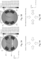
- Figures 3A and 3B are grayscale coded finite element analysis of the stress in a GaAs 1 ⁇ 2 VCSEL 112 after thermocompression bonding.
- the gold pads GP1-GP4 are under heavy stress.
- Figure 3A shows the x-component of the stress is along the GaAs 110 crystal direction.
- the x-component stress in high in region XS surrounding the device's optical axis OA.
- Figure 3B shows the y-component of the stress is elevated only in regions away YS, which are from the optical axis.
- the crystal is made birefringent, so it maintains polarization the same way a polarization-maintaining fiber does. Also, an optical gain asymmetry develops for polarizations aligned along the 110 and 1 10 crystal directions. (These crystal orientations are chosen for illustration purposes; other orientations could be chosen, however.)
- FIG. 4A shows how the wafer bonding transforms the symmetrically compressed quantum wells ( Fig. 4A ) to the asymmetrically compressed wells ( Fig. 4B ) because of the subtraction of the stress due to the wafer bonding process.
- the highest stress is along the 1 10-crystal orientation (z direction) so the optical gain is highest in the z direction as well.
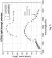
- FIG. 5 This figure shows experimental results. It illustrates linear polarization for a 1050 nm tunable VCSEL. The polarization is aligned along the highest stress axis of the bonded die crystal.
Landscapes
- Physics & Mathematics (AREA)
- Condensed Matter Physics & Semiconductors (AREA)
- General Physics & Mathematics (AREA)
- Electromagnetism (AREA)
- Optics & Photonics (AREA)
- Semiconductor Lasers (AREA)
Description
- Vertical cavity surface emitting lasers (VCSELs) need some sort of asymmetry built into the device to select for controlled linear polarized output. This asymmetry can be provided by rectangular mesas [1], high contrast grating mirrors [2,3], subwavelength gratings [4], possible strain from oxidized DBR mirrors [5], asymmetric metal strain films applied to the crystal [6], asymmetric current apertures [8,9], surface gratings [10], growth on tilted crystal planes [11,12], externally induced asymmetric strain [13], polarization loss anisotropy [14], or asymmetric current injection [15].
- Yano T et al: "Wavelength Modulation over 500 kHz of Micromechanically Tunable InP-based VCSELs with Si-MEMs Technology" , IEEE Journal of Selected Topics in Quantum Electronics, IEEE Service Centre Piscataway, NJ, US, vol. 15, no. 3, 1 May 2009, pages 528-534, XP 011344224 describes wavelength modulation over 500 kHz by a micromechanically tunable vertical-cavity surface-emitting laser (VCSEL) consisting of an InP-based half-VCSEL chip and micromachined silicon-on-insulator chip with a concave movable mirror.
- The present invention concerns a design and method for introducing asymmetric crystal strain to control polarization in a tunable VCSEL, either optically or electrically pumped. The scope of protection is determined from the claims.
- The invention is especially relevant to wafer- or die- bonded tunable VCSELs. Examples of such devices are disclosed in
United States Patent Application US20140176958A1, by Flanders, Kuznetsov, Atia, and Johnson , "OCT System with Bonded MEMS Tunable Mirror VCSEL Swept Source". - In general, according to one aspect, the invention features a vertical cavity surface emitting lasers (VCSEL), comprising a membrane device and a half VCSEL device. Then, mechanical stress is applied to the half VCSEL device.
- This mechanical stress controls a polarization of light generated by the VCSEL. In the present design, the mechanical stress is applied by the membrane device to the half VCSEL device.
- Preferably, the mechanical stress is generated by bonding the membrane device to the half VCSEL device under elevated temperature. At the same time, the VCSEL device and the membrane device have different coefficients of thermal expansion. Preferably, the membrane device is thermocompression bonded to the half VCSEL device.
- In general, according to another aspect, the invention features a VCSEL, comprising a membrane device, a half VCSEL device, and bond pads attaching the membrane device to the half VCSEL device. A distance between the bond pads is different between two axes of a plane of the membrane device and the half VCSEL device. This asymmetric is used to create mechanical stress in the half VCSEL device.
- In general, according to another aspect, the invention features a method for fabricating a VCSEL, the method comprising: fabricating a membrane device, fabricating a half VCSEL device, and bonding the membrane device to the half VCSEL device to induce mechanical stress in the half VCSEL device.
- The above and other features of the invention including various novel details of construction and combinations of parts, and other advantages, will now be more particularly described with reference to the accompanying drawings and pointed out in the claims. It will be understood that the particular method and device embodying the invention are shown by way of illustration and not as a limitation of the invention. The principles and features of this invention may be employed in various and numerous embodiments without departing from the scope of the invention as defined by the appended claims.
- In the accompanying drawings, reference characters refer to the same parts throughout the different views. The drawings are not necessarily to scale; emphasis has instead been placed upon illustrating the principles of the invention. Of the drawings:
-
Fig. 1 is an exploded perspective view of a wafer- or die- bonded tunable VCSEL to which the present invention is applicable; -
Fig. 2 is a schematic perspective view of the half VCSEL showing the locations of the bond pads. -
Figs. 3A and 3B are finite element analyses of the stress on the ½ VCSEL; -
Figs. 4A and 4B schematically illustrates the change in stress resulting from the wafer bonding process in the ½ VCSEL; -
Fig. 5 is a plot of optical power (dBm) as a function of wavelength for the different polarizations. - The invention now will be described more fully hereinafter with reference to the accompanying drawings, in which illustrative embodiments of the invention are shown. This invention may, however, be embodied in many different forms and should not be construed as limited to the embodiments set forth herein; rather, these embodiments are provided so that this disclosure will be thorough and complete, and will fully convey the scope of the invention to those skilled in the art.
- As used herein, the term "and/or" includes any and all combinations of one or more of the associated listed items. Further, the singular forms and the articles "a", "an" and "the" are intended to include the plural forms as well, unless expressly stated otherwise. It will be further understood that the terms: includes, comprises, including and/or comprising, when used in this specification, specify the presence of stated features, integers, steps, operations, elements, and/or components, but do not preclude the presence or addition of one or more other features, integers, steps, operations, elements, components, and/or groups thereof. Further, it will be understood that when an element, including component or subsystem, is referred to and/or shown as being connected or coupled to another element, it can be directly connected or coupled to the other element or intervening elements may be present.
- Unless otherwise defined, all terms (including technical and scientific terms) used herein have the same meaning as commonly understood by one of ordinary skill in the art to which this invention belongs. It will be further understood that terms, such as those defined in commonly used dictionaries, should be interpreted as having a meaning that is consistent with their meaning in the context of the relevant art and will not be interpreted in an idealized or overly formal sense unless expressly so defined herein.
-
Fig. 1 shows a MEMStunable VCSEL 100 comprising a MEMS membrane (mirror)device 110 that is bonded to what is termed a half VCSEL chip ordevice 112. - In more detail, the
optical membrane device 110 comprises handlewafer material 210 that functions as a support. Currently, the handle is made from doped silicon, with a resistivity <0.1 ohm-cm, carrier concentration >1×1017 cm-3, to facilitate electrical contact. - An optical membrane or
device layer 212 is added to thehandle wafer material 210. Typically silicon on isolator (SOI) wafers are used. Anoptical membrane structure 214 is formed in thisoptical membrane layer 212. In the current implementation, themembrane layer 212 is silicon that is low doped with resistivity >1 ohm-cm, carrier concentration <5 × 1015 cm-3, to minimize free carrier absorption of the transmitted light. For electrical contact, the membrane layer surface is usually additionally doped by ion implantation to create a highly doped surface layer (doped usually to > 1 × 1018 cm-3, but at least 1 × 1017 cm-3 and at least 200 Angstroms (A) thick, usually 500-2000 A thick). This method minimizes optical absorption in the membrane layer itself that would occur if the entire layer were highly doped. An insulating (buried silicon dioxide)layer 216 separates theoptical membrane layer 212 from thehandle wafer material 210. - During manufacture of the membrane device in the SOIwafer material, the
insulating layer 216 functions as a sacrificial/release layer, which is partially removed to release themembrane structure 214 from thehandle wafer material 210. Then during operation, the remaining portions of theinsulating layer 216 provide electrical isolation between thepatterned device layer 212 and thehandle material 210. - In the current embodiment, the
membrane structure 214 comprises abody portion 218. The optical axis of thedevice 100 passes concentrically through thisbody portion 218 and orthogonal to a plane defined by themembrane layer 212. A diameter of thisbody portion 218 is preferably 300 to 600 micrometers; currently it is about 500 micrometers. - Tethers 220 (four tethers in the illustrated example) defined and delineated by
arcuate slots 225 fabricated into thedevice layer 212. Thetethers 220 extend radially from thebody portion 218 to anouter portion 222, which comprises the ring where thetethers 220 terminate. In the current embodiment, a spiral tether pattern is used. - A
membrane mirror dot 250 is disposed onbody portion 218 of themembrane structure 214. In some embodiments, themembrane mirror 250 is an optically curved to form an optically concave optical element to thereby form a curved mirror laser cavity. In other cases, themembrane mirror 250 is a flat mirror, or even possibly convex. - When a
curved membrane mirror 250 is desired, this curvature can be created by forming a depression in thebody portion 218 and then depositing the material layer or layers that formmirror 250 over that depression. In other examples, themembrane mirror 250 can be deposited with a high amount of compressive material stress that will result in its curvature. - The membrane mirror dot 250 is preferably a reflecting dielectric mirror stack. In some examples, it is a dichroic mirror-filter that provides a defined reflectivity, such as between 1 and 99.9%, to the wavelengths of laser light generated in the
laser 100, whereas theoptical dot 250 is transmissive to wavelengths of light that are used to optically pump the active region in theVCSEL device 112. In still other examples, the optical dot is a reflective metal layer such as aluminum or gold. - In the illustrated embodiment, four metal pads MP1, MP2, MP3, and MP4 are deposited on the proximal side of the
membrane device 110. These are used to solder or thermocompression bond, for example, thehalf VCSEL device 112 onto the proximal face of themembrane device 110. - Also provided are two wire bondpads 334A, 334B. Membrane
wire bond pad 334A is used to provide an electrical connection to themembrane layer 212 and thus themembrane structure 214. The handlewire bond pad 334B is used to provide an electrical connection to thehandle wafer material 210. - The
half VCSEL device 112 generally comprises anantireflective coating 114, which is optional, and anactive region 118, which preferably has a single or multiple quantum well structure. The cap layer can be used between theantireflective coating 114, if present, and theactive region 118. The cap layer protects the active region from the surface/interface effects at the interface to the AR coating and/or air. Theback mirror 116 of the laser cavity is defined by a distributed Bragg reflector (DBR) mirror. Finally, ahalf VCSEL spacer 115, such as GaAS, functions as a substrate and mechanical support. The DBR can be grown into the semiconductor, or be a deposited dielectric DBR, or hybrid metal/dielectric mirror deposited near the active layer after etching a hole or "port" in the semiconductor substrate. - The material system of the
active region 118 of theVCSEL device 112 is selected based on the desired spectral operating range. Common material systems are based on III-V semiconductor materials, including binary materials, such as GaN, GaAs, InP, GaSb, InAs, as well as ternary, quaternary, and pentenary alloys, such as InGaN, InAlGaN, InGaP, AlGaAs, InGaAs, GaInNAs, GaInNAsSb, AlInGaAs, InGaAsP, AlGaAsSb, AlGaInAsSb, AlAsSb, InGaSb, InAsSb, and InGaAsSb. Collectively, these material systems support operating wavelengths from about 400 nanometers (nm) to 2000 nm, including longer wavelength ranges extending into multiple micrometer wavelengths. Semiconductor quantum well and quantum dot gain regions are typically used to obtain especially wide gain and spectral emission bandwidths. Quantum well layers may be purposely strained or unstrained depending the exact materials and the desired wavelength coverage. - In still other examples, the rear VCSEL distributed Bragg reflector (DBR)
mirror 116 is a dichroic mirror-filter that provides a defined reflectivity, such as greater than 99% to the wavelengths of laser light generated in thelaser 100, whereas therear mirror 116 is transmissive to wavelengths of light that are used to optically pump the active region in theVCSEL device 112, thus allowing thehalf VCSEL device 112 to function as an input port of pump light. - In the example of a VCSEL operating with a center wavelength around 1050 nm, the mirror reflectivities tend toward higher numbers for light around 1050 nm in wavelength. For example, the reflectivity of the
back mirror 116 is about 99.99%. On the other hand, thefront mirror dot 250 is usually 99% or greater. In current embodiments, themirror dot 250 has a reflectivity of about 99.4% or higher. - In operation, the VCSEL device is electrically or optically pumped. The generated light resonates between the
rear mirror 116 andmembrane mirror 250. The wavelength of the generated light is tuned within the scan band of the device by the out of plane electrostatic deflection of thebody portion 218 and thus themembrane mirror 250 by controlling the electrostatic field between thebody portion 218 and thehandle wafer material 210 and/or thehalf VCSEL device 112. - According to the invention, asymmetric mechanical stress is applied to the
half VCSEL device 112 in order to obtain polarization control. -
Fig. 2 is schematic view showing the hidden bond pads VP1-VP4 on thehalf VCSEL device 112. - The asymmetric strain is created in the ½
VCSEL device 112 by the die bonding process. In one embodiment using thermocompression bonding, thin gold pads VP1-VP4 on the ½VCSEL device 112 are bonded to corresponding membrane pads MP1, MP2, MP3, and MP4 of the MEMS membrane (mirror)device 110 by placing them in contact at high pressure and temperature to form the bond. Typically, this is done at 300 - 360°C and 1 - 10N force. Other elevated temperature bonding methods, such as gold-tin and/or eutectic soldering, can be used to produce a similar effect, however. - The two substrates (½
VCSEL device 112/MEMS membrane (mirror) device 110) are made of different materials. The MEMS membrane (mirror)device 110 is made on a silicon substrate. The gain medium of thehalf VCSEL device 112 is typically grown on a direct bandgap semiconductor substrate such as GaAs or InP. - The bond is made between unstrained materials at high temperature. When the bonded structure cools, however, strain is introduced because of the different coefficients of thermal expansion (CTE) between the silicon
MEMS membrane device 110 and the substrate material used for the optical gain medium of thehalf VCSEL device 112. Although this procedure can be performed for many different materials systems, here we will use an example of InGaAs quantum well active or gain medium 118 on a GaAssubstrate VCSEL spacer 115 that lases near 1050 nm. Generally, this material system is used to generate light in the 980-1100 nm range. The VCSEL is tunable to sweep its output through a band, which is typically greater than 50 nm wide and often more than 100 nm wide, centered on 1050 nm. - An asymmetric bond pad arrangement is used to produce asymmetric stress. Specifically, the bond pad arrangement is asymmetric in that the x-axis distance (X1) between the pads is greater than the z-axis distance (Z1) between the pads. Said another way, a distance between the bond pads is different between two axes of a plane of the membrane device and the half VCSEL device. The bond pad asymmetry is designed so that the added stress asymmetry to the ½ VCSEL from bonding to the
membrane device 112 is between 20 and 100 MPa. -
Figures 3A and 3B are grayscale coded finite element analysis of the stress in a GaAs ½VCSEL 112 after thermocompression bonding. The gold pads GP1-GP4 are under heavy stress. -
Figure 3A shows the x-component of the stress is along theGaAs 110 crystal direction. In general, the x-component stress in high in region XS surrounding the device's optical axis OA. - On the other hand,
Figure 3B shows the y-component of the stress is elevated only in regions away YS, which are from the optical axis. - Two effects in the strained crystal control the polarization. The crystal is made birefringent, so it maintains polarization the same way a polarization-maintaining fiber does. Also, an optical gain asymmetry develops for polarizations aligned along the 110 and 110 crystal directions. (These crystal orientations are chosen for illustration purposes; other orientations could be chosen, however.)
- The following comments apply to many different quantum well material systems at many different wavelength ranges, both strained and unstrained as grown, but here the InGaAs/GaAs material system for the 1050 nm range is used as an example. With compressively strained InGaAs quantum wells, tunable lasers generated tunable swept wavelength optical signal in the range 980-1100 nm or more can be constructed. The compressive strain shifts the emission to longer wavelengths and increases the optical gain for TE (transverse electric field) polarization, polarized in the plane of the quantum well layers. The compressive stress fields before and after wafer bonding are shown in
Figs. 4A and 4B , respectively. These figures show how the wafer bonding transforms the symmetrically compressed quantum wells (Fig. 4A ) to the asymmetrically compressed wells (Fig. 4B ) because of the subtraction of the stress due to the wafer bonding process. The highest stress is along the 110-crystal orientation (z direction) so the optical gain is highest in the z direction as well. - The gain is higher for the z-polarization, so the VCSEL lases with that polarization as shown in
Fig. 5 . This figure shows experimental results. It illustrates linear polarization for a 1050 nm tunable VCSEL. The polarization is aligned along the highest stress axis of the bonded die crystal. -
- [1] Y. Sato, T. Mori, Y. Yamayoshi, and H. Kawaguchi, "Polarization Bistable Characteristics of Mesa Structure 980nm Vertical-Cavity Surface-Emitting Lasers", Japanese Journal of Applied Physics, 45, L438-L440, (2006)
- [2] Y. Rao, W. Yang, C. Chase, M.C.Y. Huang, D.P. Worland, S. Khaleghi, M.R. Chitgarha, M. Ziyadi, A.E. Willner, and C.J. Chang-Hasnain, "Long-Wavelength VCSEL Using High-Contrast Grating", IEEE J. Selected Topics in Quantum Electronics, 19, 1701311-1701311 (2013)
- [3] Thor Ansbæk Ph.D. thesis, "Vertical-cavity surface-emitting lasers for medical diagnosis", Department of Photonics Engineering at The Technical University of Denmark (2012)
- [4] M. Ortsiefer, M. Goerblich, Y. Xu et al., Polarization control in buried tunnel junction VCSELs using a birefringent semiconductor/dielectric subwavelength grating. IEEE Photon. Technol. Lett. 22, 15-17 (2010)
- [5] V. Jayaraman, J. Jiang, B. Potsaid, M. Robertson, P.J.S. Heim, C. Burgner, D. John, G.D. Cole, I. Grulkowski, J.G. Fujimoto, A.M. Davis, and A.E. Cable, "VCSEL Swept Light Sources", Section 22.5.4 Polarization stability, in Optical Coherence Tomography, W. Drexler, J.G. Fujimoto (eds.), Springer International Publishing Switzerland 2015.
- [6]Y. Matsui, D. Vakhshoori, P. Wang, P. Chen, C-C. Lu, M. Jiang, K. Knopp, S. Burroughs, and P. Tayebati, "Complete Polarization Mode Control of Long-Wavelength Tunable Vertical-Cavity Surface-Emitting Lasers Over 65-nm Tuning, Up to 14-mW Output Power", IEEE J. Quantum Electronics, 39, 1037-1048 (2003)
- [7]
United States Patent Application US20140176958A1, D.C. Flanders, M.E. Kuznetsov, W.A. Atia, B.C. Johnson, "OCT System with Bonded MEMS Tunable Mirror VCSEL Swept Source", Priority date 2012-12-21 . - [8] M. A. Bobrov, N. A. Maleev, S. A. Blokhin, A. G. Kuzmenkov, A. P. Vasil'ev, A. A. Blokhin, M. M. Kulagitia, Yu. A. Guseva, S. I. Troshkov, W. Lysak, and V. M. Ustinov, "VCSEL polarization control by rhomboidal selectively-oxidized current aperture", 2016 International Conference Laser Optics (LO) Page R3-16 (2016)
- [9] K-H. Ha and Y-H. Lee, "Polarization Control of Vertical-Cavity Surface-emitting Lasers by Asymmetric Oxide-aperture", (CLEO) Conference on Lasers and Electro-Optics/Pacific Rim '99 / Paper 2.30, Pages 890-891.
- [10] P. Debemardi, J.M. Ostermann, M. Feneberg, C. Jalics, and R. Michalzik, "Reliable Polarization Control of VCSELs Through Monolithically Integrated Surface Gratings: A Comparative Theoretical and Experimental Study", IEEE J. on Selected Topics in Quantum Electronics, 11, 107-116 (2005)
- [11] N. Nishiyama, M.Arai, S. Shinada, M. Azuchi, T. Miyamoto, F. Koyama, and K. Iga, "Highly Strained GaInAs-GaAs Quantum-Well Vertical-Cavity Surface-Emitting Laser on GaAs (311)B Substrate for Stable Polarization Operation", IEEE J. on Selected Topics in Quantum Electronics, 7, 242- 248 (2001)
- [12] Y.L. Okuno, J. Geske, K-G. Gan, Y-J. Chiu, S.P. DenBaars, and J.E. Bowers, "1.3 mm wavelength vertical cavity surface emitting laser fabricated by orientation-mismatched wafer bonding: A prospect for polarization control", Applied Physics Letters, 82, 2377- 2379 (2003)
- [13] J.M. Ostermann, P. Debernardi, A. Kroner, and R. Michalzik, "Polarization-Controlled Surface Grating VCSELs Under Externally Induced Anisotropic Strain", IEEE Photonics Technology Letters, 19, 1301- 1303 (2007)
- [14] T. Yoshikawa, T. Kawakami, H. Saito, H. Kosaka, M. Kajita, K. Kurihara, Y. Sugimoto, and K. Kasahara, "Polarization-Controlled Single-Mode VCSEL", IEEE J. of Quantum Electronics, 34, 1009-1015 (1998)
- [15] Y. Zheng, C-H. Lin, and L.A. Coldren, "Control of Polarization Phase Offset in Low Threshold Polarization Switching VCSELs," IEEE Photonics Technnology Letters, 23, 305-307 (2011)
- While this invention has been particularly shown and described with references to preferred embodiments thereof, it will be understood by those skilled in the art that various changes in form and details may be made therein without departing from the scope of the invention encompassed by the appended claims.
Claims (9)
- A VCSEL, comprising:a membrane device (110) including a support (210), an optical membrane structure (214) on the support, and a membrane mirror dot (250) on the membrane structure (214); anda half VCSEL device (112) including an active region (118) and a back mirror (116) which is bonded to the membrane device (110), wherein light resonates between the back mirror (116) and the membrane mirror dot (250) and a wavelength of generated light is tuned by electrostatic deflection of the optical membrane structure (214);bond pads (VP1-VP4) attaching the membrane device (110) to the half VCSEL device (112);wherein an asymmetrical mechanical stress is applied to the half VCSEL device (112) by the membrane device (110), the asymmetrical mechanical stress is configured to control a polarization of light generated by the VCSEL,wherein the VCSEL device and the membrane device have different coefficients of thermal expansion, and an asymmetric arrangement of the bond pads (VP1-VP4) is configured to produce the asymmetrical mechanical stress.
- The VCSEL of claim 1, wherein the added stress asymmetry to the half VCSEL from bonding to the membrane device (110) is between 20 and 100 MPa.
- The VCSEL of claim 1, wherein a distance between the bond pads (VP1-VP4) is different between two axes of a plane of the membrane device (110) and the half VCSEL device (112).
- A method for fabricating a VCSEL as defined in claim 1, the method comprising:fabricating a membrane device (110) including a support (210), an optical membrane structure (214) on the support, and a membrane mirror dot (250) on the membrane structure;fabricating a half VCSEL device (112) including an active region (118) and a back mirror (116) which is bonded to the membrane device, wherein light resonates between the back mirror and the membrane mirror dot (250) and a wavelength of generated light is tuned by electrostatic deflection of the optical membrane structure (214);bonding the membrane device (110) to the half VCSEL device (112) using an asymmetric arrangement of bond pads (VP1-VP4) to induce asymmetrical mechanical stress in the half VCSEL device by the membrane device (110);wherein the VCSEL device and the membrane device have different coefficients of thermal expansion, and the asymmetrical mechanical stress controls a polarization of light generated by the VCSEL.
- The method of claim 4, wherein the mechanical stress is generated by bonding the membrane device (110) to the half VCSEL device (112) under elevated temperature.
- The VCSEL of claim 1, wherein the membrane device (110) is thermocompression bonded to the half VCSEL device (112).
- The method of claim 4, further comprising metal bonding the membrane device (110) to the half VCSEL device (112).
- The method of claim 4, further comprising thermocompression bonding the membrane device (110) to the half VCSEL device (112).
- The method of claim 4, wherein the added stress asymmetry to the half VCSEL from bonding to the membrane device (110) is between 20 and 100 MPa.
Applications Claiming Priority (2)
| Application Number | Priority Date | Filing Date | Title |
|---|---|---|---|
| US201862670514P | 2018-05-11 | 2018-05-11 | |
| PCT/US2019/031800 WO2019217872A1 (en) | 2018-05-11 | 2019-05-10 | Tunable vcsel polarization control through dissimilar die bonding |
Publications (2)
| Publication Number | Publication Date |
|---|---|
| EP3791451A1 EP3791451A1 (en) | 2021-03-17 |
| EP3791451B1 true EP3791451B1 (en) | 2024-12-11 |
Family
ID=66641512
Family Applications (1)
| Application Number | Title | Priority Date | Filing Date |
|---|---|---|---|
| EP19726272.8A Active EP3791451B1 (en) | 2018-05-11 | 2019-05-10 | Tunable vcsel polarization control through dissimilar die bonding |
Country Status (4)
| Country | Link |
|---|---|
| US (1) | US10951009B2 (en) |
| EP (1) | EP3791451B1 (en) |
| DK (1) | DK3791451T3 (en) |
| WO (1) | WO2019217872A1 (en) |
Families Citing this family (5)
| Publication number | Priority date | Publication date | Assignee | Title |
|---|---|---|---|---|
| KR20210086703A (en) | 2018-11-05 | 2021-07-08 | 엑셀리타스 테크놀로지스 코포레이션 | Tunable Vertical Resonant Surface Light Laser Coupled with Bidirectional Actuation |
| KR20230114743A (en) | 2020-10-14 | 2023-08-01 | 엑셀리타스 테크놀로지스 코포레이션 | Tunable VCSEL with Strain Compensated Semiconductor DBR |
| WO2022212303A1 (en) * | 2021-03-29 | 2022-10-06 | Excelitas Technologies Corp. | Tunable vcsel polarization control with intracavity subwavelength grating |
| US11699894B2 (en) | 2021-08-16 | 2023-07-11 | Excelitas Technologies Corp. | Bonded tunable VCSEL with bi-directional actuation |
| US12691917B2 (en) | 2023-07-17 | 2026-07-28 | Bnsf Railway Company | System for testing railroad crossing signals |
Family Cites Families (5)
| Publication number | Priority date | Publication date | Assignee | Title |
|---|---|---|---|---|
| US6188711B1 (en) * | 1997-12-18 | 2001-02-13 | Agilent Technologies, Inc. | Polarization-controlled VCSELs using externally applied uniaxial stress |
| US6785318B1 (en) * | 2002-06-25 | 2004-08-31 | Nortel Networks Limited | Polarization mode control of vertical cavity surface emitting lasers |
| WO2014018945A1 (en) | 2012-07-27 | 2014-01-30 | Thorlabs.Inc. | Quantum well tunable short cavity laser |
| US20140176958A1 (en) * | 2012-12-21 | 2014-06-26 | Axsun Technologies, Inc. | OCT System with Bonded MEMS Tunable Mirror VCSEL Swept Source |
| EP3301072B1 (en) * | 2016-09-30 | 2024-02-21 | Sciosense B.V. | Semiconductor device and method for forming a semiconductor device |
-
2019
- 2019-05-10 DK DK19726272.8T patent/DK3791451T3/en active
- 2019-05-10 WO PCT/US2019/031800 patent/WO2019217872A1/en not_active Ceased
- 2019-05-10 US US16/409,295 patent/US10951009B2/en active Active
- 2019-05-10 EP EP19726272.8A patent/EP3791451B1/en active Active
Also Published As
| Publication number | Publication date |
|---|---|
| WO2019217872A1 (en) | 2019-11-14 |
| US20190348815A1 (en) | 2019-11-14 |
| EP3791451A1 (en) | 2021-03-17 |
| DK3791451T3 (en) | 2025-03-03 |
| US10951009B2 (en) | 2021-03-16 |
Similar Documents
| Publication | Publication Date | Title |
|---|---|---|
| US10951009B2 (en) | Tunable VCSEL polarization control through dissimilar die bonding | |
| US6546029B2 (en) | Micro-electromechanically tunable vertical cavity photonic device and a method of fabrication thereof | |
| US11749962B2 (en) | Optically pumped tunable VCSEL employing geometric isolation | |
| US12040594B2 (en) | Tunable VCSEL with combined gain and DBR mirror | |
| US12027821B2 (en) | Bonded tunable VCSEL with bi-directional actuation | |
| EP3005500A1 (en) | A wavelength tunable photon source with sealed inner volume | |
| US12388235B2 (en) | Tunable VCSEL polarization control with intracavity subwavelength grating | |
| EP3811473B1 (en) | Quantum well placement in a tunable vcsel | |
| Louderback et al. | VCSELs with monolithic coupling to internal horizontal waveguides using integrated diffraction gratings | |
| Chen et al. | First demonstration of a MEMS tunable vertical-cavity SOA | |
| Maute et al. | Micro-mechanically tunable long wavelength VCSEL with buried tunnel junction | |
| US11699894B2 (en) | Bonded tunable VCSEL with bi-directional actuation | |
| Strassner et al. | Progress in InP-based MOEMS | |
| Rapp | Long-wavelength vertical-cavity lasers based on indium phosphide/gallium indium arsenic phosphide Bragg reflectors |
Legal Events
| Date | Code | Title | Description |
|---|---|---|---|
| STAA | Information on the status of an ep patent application or granted ep patent |
Free format text: STATUS: UNKNOWN |
|
| STAA | Information on the status of an ep patent application or granted ep patent |
Free format text: STATUS: THE INTERNATIONAL PUBLICATION HAS BEEN MADE |
|
| PUAI | Public reference made under article 153(3) epc to a published international application that has entered the european phase |
Free format text: ORIGINAL CODE: 0009012 |
|
| STAA | Information on the status of an ep patent application or granted ep patent |
Free format text: STATUS: REQUEST FOR EXAMINATION WAS MADE |
|
| 17P | Request for examination filed |
Effective date: 20201104 |
|
| AK | Designated contracting states |
Kind code of ref document: A1 Designated state(s): AL AT BE BG CH CY CZ DE DK EE ES FI FR GB GR HR HU IE IS IT LI LT LU LV MC MK MT NL NO PL PT RO RS SE SI SK SM TR |
|
| AX | Request for extension of the european patent |
Extension state: BA ME |
|
| RIN1 | Information on inventor provided before grant (corrected) |
Inventor name: JOHNSON, BARTLEY C. Inventor name: MALONSON, MARK R. Inventor name: ATIA, WALID A. Inventor name: KUZNETSOV, MARK E. Inventor name: GETZ, JAMES W. Inventor name: WHITNEY, PETER S. |
|
| DAV | Request for validation of the european patent (deleted) | ||
| DAX | Request for extension of the european patent (deleted) | ||
| STAA | Information on the status of an ep patent application or granted ep patent |
Free format text: STATUS: EXAMINATION IS IN PROGRESS |
|
| 17Q | First examination report despatched |
Effective date: 20220215 |
|
| GRAP | Despatch of communication of intention to grant a patent |
Free format text: ORIGINAL CODE: EPIDOSNIGR1 |
|
| STAA | Information on the status of an ep patent application or granted ep patent |
Free format text: STATUS: GRANT OF PATENT IS INTENDED |
|
| RIC1 | Information provided on ipc code assigned before grant |
Ipc: H01S 5/32 20060101ALN20240619BHEP Ipc: H01S 5/06 20060101ALN20240619BHEP Ipc: H01S 5/183 20060101AFI20240619BHEP |
|
| INTG | Intention to grant announced |
Effective date: 20240705 |
|
| GRAS | Grant fee paid |
Free format text: ORIGINAL CODE: EPIDOSNIGR3 |
|
| GRAA | (expected) grant |
Free format text: ORIGINAL CODE: 0009210 |
|
| STAA | Information on the status of an ep patent application or granted ep patent |
Free format text: STATUS: THE PATENT HAS BEEN GRANTED |
|
| AK | Designated contracting states |
Kind code of ref document: B1 Designated state(s): AL AT BE BG CH CY CZ DE DK EE ES FI FR GB GR HR HU IE IS IT LI LT LU LV MC MK MT NL NO PL PT RO RS SE SI SK SM TR |
|
| REG | Reference to a national code |
Ref country code: GB Ref legal event code: FG4D |
|
| REG | Reference to a national code |
Ref country code: CH Ref legal event code: EP |
|
| REG | Reference to a national code |
Ref country code: DE Ref legal event code: R096 Ref document number: 602019063350 Country of ref document: DE |
|
| REG | Reference to a national code |
Ref country code: IE Ref legal event code: FG4D |
|
| REG | Reference to a national code |
Ref country code: DK Ref legal event code: T3 Effective date: 20250225 |
|
| REG | Reference to a national code |
Ref country code: LT Ref legal event code: MG9D |
|
| PG25 | Lapsed in a contracting state [announced via postgrant information from national office to epo] |
Ref country code: HR Free format text: LAPSE BECAUSE OF FAILURE TO SUBMIT A TRANSLATION OF THE DESCRIPTION OR TO PAY THE FEE WITHIN THE PRESCRIBED TIME-LIMIT Effective date: 20241211 |
|
| PG25 | Lapsed in a contracting state [announced via postgrant information from national office to epo] |
Ref country code: FI Free format text: LAPSE BECAUSE OF FAILURE TO SUBMIT A TRANSLATION OF THE DESCRIPTION OR TO PAY THE FEE WITHIN THE PRESCRIBED TIME-LIMIT Effective date: 20241211 |
|
| PG25 | Lapsed in a contracting state [announced via postgrant information from national office to epo] |
Ref country code: BG Free format text: LAPSE BECAUSE OF FAILURE TO SUBMIT A TRANSLATION OF THE DESCRIPTION OR TO PAY THE FEE WITHIN THE PRESCRIBED TIME-LIMIT Effective date: 20241211 |
|
| REG | Reference to a national code |
Ref country code: NL Ref legal event code: MP Effective date: 20241211 |
|
| PG25 | Lapsed in a contracting state [announced via postgrant information from national office to epo] |
Ref country code: ES Free format text: LAPSE BECAUSE OF FAILURE TO SUBMIT A TRANSLATION OF THE DESCRIPTION OR TO PAY THE FEE WITHIN THE PRESCRIBED TIME-LIMIT Effective date: 20241211 |
|
| PG25 | Lapsed in a contracting state [announced via postgrant information from national office to epo] |
Ref country code: NO Free format text: LAPSE BECAUSE OF FAILURE TO SUBMIT A TRANSLATION OF THE DESCRIPTION OR TO PAY THE FEE WITHIN THE PRESCRIBED TIME-LIMIT Effective date: 20250311 |
|
| PG25 | Lapsed in a contracting state [announced via postgrant information from national office to epo] |
Ref country code: GR Free format text: LAPSE BECAUSE OF FAILURE TO SUBMIT A TRANSLATION OF THE DESCRIPTION OR TO PAY THE FEE WITHIN THE PRESCRIBED TIME-LIMIT Effective date: 20250312 Ref country code: LV Free format text: LAPSE BECAUSE OF FAILURE TO SUBMIT A TRANSLATION OF THE DESCRIPTION OR TO PAY THE FEE WITHIN THE PRESCRIBED TIME-LIMIT Effective date: 20241211 |
|
| PG25 | Lapsed in a contracting state [announced via postgrant information from national office to epo] |
Ref country code: RS Free format text: LAPSE BECAUSE OF FAILURE TO SUBMIT A TRANSLATION OF THE DESCRIPTION OR TO PAY THE FEE WITHIN THE PRESCRIBED TIME-LIMIT Effective date: 20250311 |
|
| P01 | Opt-out of the competence of the unified patent court (upc) registered |
Free format text: CASE NUMBER: APP_16913/2025 Effective date: 20250407 |
|
| PG25 | Lapsed in a contracting state [announced via postgrant information from national office to epo] |
Ref country code: NL Free format text: LAPSE BECAUSE OF FAILURE TO SUBMIT A TRANSLATION OF THE DESCRIPTION OR TO PAY THE FEE WITHIN THE PRESCRIBED TIME-LIMIT Effective date: 20241211 |
|
| REG | Reference to a national code |
Ref country code: AT Ref legal event code: MK05 Ref document number: 1751136 Country of ref document: AT Kind code of ref document: T Effective date: 20241211 |
|
| PG25 | Lapsed in a contracting state [announced via postgrant information from national office to epo] |
Ref country code: SM Free format text: LAPSE BECAUSE OF FAILURE TO SUBMIT A TRANSLATION OF THE DESCRIPTION OR TO PAY THE FEE WITHIN THE PRESCRIBED TIME-LIMIT Effective date: 20241211 |
|
| PG25 | Lapsed in a contracting state [announced via postgrant information from national office to epo] |
Ref country code: PL Free format text: LAPSE BECAUSE OF FAILURE TO SUBMIT A TRANSLATION OF THE DESCRIPTION OR TO PAY THE FEE WITHIN THE PRESCRIBED TIME-LIMIT Effective date: 20241211 |
|
| PG25 | Lapsed in a contracting state [announced via postgrant information from national office to epo] |
Ref country code: IS Free format text: LAPSE BECAUSE OF FAILURE TO SUBMIT A TRANSLATION OF THE DESCRIPTION OR TO PAY THE FEE WITHIN THE PRESCRIBED TIME-LIMIT Effective date: 20250411 |
|
| PG25 | Lapsed in a contracting state [announced via postgrant information from national office to epo] |
Ref country code: PT Free format text: LAPSE BECAUSE OF FAILURE TO SUBMIT A TRANSLATION OF THE DESCRIPTION OR TO PAY THE FEE WITHIN THE PRESCRIBED TIME-LIMIT Effective date: 20250411 |
|
| PG25 | Lapsed in a contracting state [announced via postgrant information from national office to epo] |
Ref country code: EE Free format text: LAPSE BECAUSE OF FAILURE TO SUBMIT A TRANSLATION OF THE DESCRIPTION OR TO PAY THE FEE WITHIN THE PRESCRIBED TIME-LIMIT Effective date: 20241211 |
|
| PG25 | Lapsed in a contracting state [announced via postgrant information from national office to epo] |
Ref country code: RO Free format text: LAPSE BECAUSE OF FAILURE TO SUBMIT A TRANSLATION OF THE DESCRIPTION OR TO PAY THE FEE WITHIN THE PRESCRIBED TIME-LIMIT Effective date: 20241211 Ref country code: AT Free format text: LAPSE BECAUSE OF FAILURE TO SUBMIT A TRANSLATION OF THE DESCRIPTION OR TO PAY THE FEE WITHIN THE PRESCRIBED TIME-LIMIT Effective date: 20241211 |
|
| PG25 | Lapsed in a contracting state [announced via postgrant information from national office to epo] |
Ref country code: SK Free format text: LAPSE BECAUSE OF FAILURE TO SUBMIT A TRANSLATION OF THE DESCRIPTION OR TO PAY THE FEE WITHIN THE PRESCRIBED TIME-LIMIT Effective date: 20241211 |
|
| PG25 | Lapsed in a contracting state [announced via postgrant information from national office to epo] |
Ref country code: CZ Free format text: LAPSE BECAUSE OF FAILURE TO SUBMIT A TRANSLATION OF THE DESCRIPTION OR TO PAY THE FEE WITHIN THE PRESCRIBED TIME-LIMIT Effective date: 20241211 |
|
| PG25 | Lapsed in a contracting state [announced via postgrant information from national office to epo] |
Ref country code: IT Free format text: LAPSE BECAUSE OF FAILURE TO SUBMIT A TRANSLATION OF THE DESCRIPTION OR TO PAY THE FEE WITHIN THE PRESCRIBED TIME-LIMIT Effective date: 20241211 |
|
| PG25 | Lapsed in a contracting state [announced via postgrant information from national office to epo] |
Ref country code: SE Free format text: LAPSE BECAUSE OF FAILURE TO SUBMIT A TRANSLATION OF THE DESCRIPTION OR TO PAY THE FEE WITHIN THE PRESCRIBED TIME-LIMIT Effective date: 20241211 |
|
| REG | Reference to a national code |
Ref country code: DE Ref legal event code: R097 Ref document number: 602019063350 Country of ref document: DE |
|
| PLBE | No opposition filed within time limit |
Free format text: ORIGINAL CODE: 0009261 |
|
| STAA | Information on the status of an ep patent application or granted ep patent |
Free format text: STATUS: NO OPPOSITION FILED WITHIN TIME LIMIT |
|
| REG | Reference to a national code |
Ref country code: CH Ref legal event code: L10 Free format text: ST27 STATUS EVENT CODE: U-0-0-L10-L00 (AS PROVIDED BY THE NATIONAL OFFICE) Effective date: 20251022 |
|
| 26N | No opposition filed |
Effective date: 20250912 |
|
| REG | Reference to a national code |
Ref country code: CH Ref legal event code: H13 Free format text: ST27 STATUS EVENT CODE: U-0-0-H10-H13 (AS PROVIDED BY THE NATIONAL OFFICE) Effective date: 20251223 |
|
| PG25 | Lapsed in a contracting state [announced via postgrant information from national office to epo] |
Ref country code: LU Free format text: LAPSE BECAUSE OF NON-PAYMENT OF DUE FEES Effective date: 20250510 |
|
| PG25 | Lapsed in a contracting state [announced via postgrant information from national office to epo] |
Ref country code: CH Free format text: LAPSE BECAUSE OF NON-PAYMENT OF DUE FEES Effective date: 20250531 |
|
| REG | Reference to a national code |
Ref country code: BE Ref legal event code: MM Effective date: 20250531 |
|
| PG25 | Lapsed in a contracting state [announced via postgrant information from national office to epo] |
Ref country code: MC Free format text: LAPSE BECAUSE OF FAILURE TO SUBMIT A TRANSLATION OF THE DESCRIPTION OR TO PAY THE FEE WITHIN THE PRESCRIBED TIME-LIMIT Effective date: 20241211 |
|
| PG25 | Lapsed in a contracting state [announced via postgrant information from national office to epo] |
Ref country code: IE Free format text: LAPSE BECAUSE OF NON-PAYMENT OF DUE FEES Effective date: 20250510 |
|
| PG25 | Lapsed in a contracting state [announced via postgrant information from national office to epo] |
Ref country code: BE Free format text: LAPSE BECAUSE OF NON-PAYMENT OF DUE FEES Effective date: 20250531 |
|
| PG25 | Lapsed in a contracting state [announced via postgrant information from national office to epo] |
Ref country code: FR Free format text: LAPSE BECAUSE OF NON-PAYMENT OF DUE FEES Effective date: 20250531 |
|
| PG25 | Lapsed in a contracting state [announced via postgrant information from national office to epo] |
Ref country code: LT Free format text: LAPSE BECAUSE OF FAILURE TO SUBMIT A TRANSLATION OF THE DESCRIPTION OR TO PAY THE FEE WITHIN THE PRESCRIBED TIME-LIMIT Effective date: 20241211 |
|
| PGFP | Annual fee paid to national office [announced via postgrant information from national office to epo] |
Ref country code: DK Payment date: 20260525 Year of fee payment: 8 Ref country code: GB Payment date: 20260527 Year of fee payment: 8 |
|
| PGFP | Annual fee paid to national office [announced via postgrant information from national office to epo] |
Ref country code: DE Payment date: 20260528 Year of fee payment: 8 |
|
| PG25 | Lapsed in a contracting state [announced via postgrant information from national office to epo] |
Ref country code: CY Free format text: LAPSE BECAUSE OF FAILURE TO SUBMIT A TRANSLATION OF THE DESCRIPTION OR TO PAY THE FEE WITHIN THE PRESCRIBED TIME-LIMIT Effective date: 20241211 |