EP3790803B1 - Composite panel comprising a perforated metallic foil for lightning strike protection - Google Patents
Composite panel comprising a perforated metallic foil for lightning strike protection Download PDFInfo
- Publication number
- EP3790803B1 EP3790803B1 EP19718162.1A EP19718162A EP3790803B1 EP 3790803 B1 EP3790803 B1 EP 3790803B1 EP 19718162 A EP19718162 A EP 19718162A EP 3790803 B1 EP3790803 B1 EP 3790803B1
- Authority
- EP
- European Patent Office
- Prior art keywords
- metallic foil
- perforated metallic
- composite panel
- apertures
- weight
- Prior art date
- Legal status (The legal status is an assumption and is not a legal conclusion. Google has not performed a legal analysis and makes no representation as to the accuracy of the status listed.)
- Active
Links
Images




Classifications
-
- B—PERFORMING OPERATIONS; TRANSPORTING
- B64—AIRCRAFT; AVIATION; COSMONAUTICS
- B64D—EQUIPMENT FOR FITTING IN OR TO AIRCRAFT; FLIGHT SUITS; PARACHUTES; ARRANGEMENT OR MOUNTING OF POWER PLANTS OR PROPULSION TRANSMISSIONS IN AIRCRAFT
- B64D45/00—Aircraft indicators or protectors not otherwise provided for
- B64D45/02—Lightning protectors; Static dischargers
-
- B—PERFORMING OPERATIONS; TRANSPORTING
- B32—LAYERED PRODUCTS
- B32B—LAYERED PRODUCTS, i.e. PRODUCTS BUILT-UP OF STRATA OF FLAT OR NON-FLAT, e.g. CELLULAR OR HONEYCOMB, FORM
- B32B15/00—Layered products comprising a layer of metal
- B32B15/04—Layered products comprising a layer of metal comprising metal as the main or only constituent of a layer, which is next to another layer of the same or of a different material
- B32B15/08—Layered products comprising a layer of metal comprising metal as the main or only constituent of a layer, which is next to another layer of the same or of a different material of synthetic resin
- B32B15/092—Layered products comprising a layer of metal comprising metal as the main or only constituent of a layer, which is next to another layer of the same or of a different material of synthetic resin comprising epoxy resins
-
- B—PERFORMING OPERATIONS; TRANSPORTING
- B32—LAYERED PRODUCTS
- B32B—LAYERED PRODUCTS, i.e. PRODUCTS BUILT-UP OF STRATA OF FLAT OR NON-FLAT, e.g. CELLULAR OR HONEYCOMB, FORM
- B32B15/00—Layered products comprising a layer of metal
- B32B15/14—Layered products comprising a layer of metal next to a fibrous or filamentary layer
-
- B—PERFORMING OPERATIONS; TRANSPORTING
- B32—LAYERED PRODUCTS
- B32B—LAYERED PRODUCTS, i.e. PRODUCTS BUILT-UP OF STRATA OF FLAT OR NON-FLAT, e.g. CELLULAR OR HONEYCOMB, FORM
- B32B15/00—Layered products comprising a layer of metal
- B32B15/20—Layered products comprising a layer of metal comprising aluminium or copper
-
- B—PERFORMING OPERATIONS; TRANSPORTING
- B32—LAYERED PRODUCTS
- B32B—LAYERED PRODUCTS, i.e. PRODUCTS BUILT-UP OF STRATA OF FLAT OR NON-FLAT, e.g. CELLULAR OR HONEYCOMB, FORM
- B32B3/00—Layered products comprising a layer with external or internal discontinuities or unevennesses, or a layer of non-planar shape; Layered products comprising a layer having particular features of form
- B32B3/10—Layered products comprising a layer with external or internal discontinuities or unevennesses, or a layer of non-planar shape; Layered products comprising a layer having particular features of form characterised by a discontinuous layer, i.e. formed of separate pieces of material
- B32B3/12—Layered products comprising a layer with external or internal discontinuities or unevennesses, or a layer of non-planar shape; Layered products comprising a layer having particular features of form characterised by a discontinuous layer, i.e. formed of separate pieces of material characterised by a layer of regularly- arranged cells, e.g. a honeycomb structure
-
- B—PERFORMING OPERATIONS; TRANSPORTING
- B32—LAYERED PRODUCTS
- B32B—LAYERED PRODUCTS, i.e. PRODUCTS BUILT-UP OF STRATA OF FLAT OR NON-FLAT, e.g. CELLULAR OR HONEYCOMB, FORM
- B32B3/00—Layered products comprising a layer with external or internal discontinuities or unevennesses, or a layer of non-planar shape; Layered products comprising a layer having particular features of form
- B32B3/26—Layered products comprising a layer with external or internal discontinuities or unevennesses, or a layer of non-planar shape; Layered products comprising a layer having particular features of form characterised by a particular shape of the outline of the cross-section of a continuous layer; characterised by a layer with cavities or internal voids ; characterised by an apertured layer
- B32B3/266—Layered products comprising a layer with external or internal discontinuities or unevennesses, or a layer of non-planar shape; Layered products comprising a layer having particular features of form characterised by a particular shape of the outline of the cross-section of a continuous layer; characterised by a layer with cavities or internal voids ; characterised by an apertured layer characterised by an apertured layer, the apertures going through the whole thickness of the layer, e.g. expanded metal, perforated layer, slit layer regular cells B32B3/12
-
- B—PERFORMING OPERATIONS; TRANSPORTING
- B32—LAYERED PRODUCTS
- B32B—LAYERED PRODUCTS, i.e. PRODUCTS BUILT-UP OF STRATA OF FLAT OR NON-FLAT, e.g. CELLULAR OR HONEYCOMB, FORM
- B32B5/00—Layered products characterised by the non- homogeneity or physical structure, i.e. comprising a fibrous, filamentary, particulate or foam layer; Layered products characterised by having a layer differing constitutionally or physically in different parts
- B32B5/22—Layered products characterised by the non- homogeneity or physical structure, i.e. comprising a fibrous, filamentary, particulate or foam layer; Layered products characterised by having a layer differing constitutionally or physically in different parts characterised by the presence of two or more layers which are next to each other and are fibrous, filamentary, formed of particles or foamed
- B32B5/24—Layered products characterised by the non- homogeneity or physical structure, i.e. comprising a fibrous, filamentary, particulate or foam layer; Layered products characterised by having a layer differing constitutionally or physically in different parts characterised by the presence of two or more layers which are next to each other and are fibrous, filamentary, formed of particles or foamed one layer being a fibrous or filamentary layer
- B32B5/26—Layered products characterised by the non- homogeneity or physical structure, i.e. comprising a fibrous, filamentary, particulate or foam layer; Layered products characterised by having a layer differing constitutionally or physically in different parts characterised by the presence of two or more layers which are next to each other and are fibrous, filamentary, formed of particles or foamed one layer being a fibrous or filamentary layer another layer next to it also being fibrous or filamentary
-
- B—PERFORMING OPERATIONS; TRANSPORTING
- B32—LAYERED PRODUCTS
- B32B—LAYERED PRODUCTS, i.e. PRODUCTS BUILT-UP OF STRATA OF FLAT OR NON-FLAT, e.g. CELLULAR OR HONEYCOMB, FORM
- B32B7/00—Layered products characterised by the relation between layers; Layered products characterised by the relative orientation of features between layers, or by the relative values of a measurable parameter between layers, i.e. products comprising layers having different physical, chemical or physicochemical properties; Layered products characterised by the interconnection of layers
- B32B7/04—Interconnection of layers
- B32B7/12—Interconnection of layers using interposed adhesives or interposed materials with bonding properties
-
- B—PERFORMING OPERATIONS; TRANSPORTING
- B32—LAYERED PRODUCTS
- B32B—LAYERED PRODUCTS, i.e. PRODUCTS BUILT-UP OF STRATA OF FLAT OR NON-FLAT, e.g. CELLULAR OR HONEYCOMB, FORM
- B32B2262/00—Composition or structural features of fibres which form a fibrous or filamentary layer or are present as additives
- B32B2262/10—Inorganic fibres
- B32B2262/106—Carbon fibres, e.g. graphite fibres
-
- B—PERFORMING OPERATIONS; TRANSPORTING
- B32—LAYERED PRODUCTS
- B32B—LAYERED PRODUCTS, i.e. PRODUCTS BUILT-UP OF STRATA OF FLAT OR NON-FLAT, e.g. CELLULAR OR HONEYCOMB, FORM
- B32B2307/00—Properties of the layers or laminate
- B32B2307/20—Properties of the layers or laminate having particular electrical or magnetic properties, e.g. piezoelectric
- B32B2307/202—Conductive
-
- B—PERFORMING OPERATIONS; TRANSPORTING
- B32—LAYERED PRODUCTS
- B32B—LAYERED PRODUCTS, i.e. PRODUCTS BUILT-UP OF STRATA OF FLAT OR NON-FLAT, e.g. CELLULAR OR HONEYCOMB, FORM
- B32B2307/00—Properties of the layers or laminate
- B32B2307/20—Properties of the layers or laminate having particular electrical or magnetic properties, e.g. piezoelectric
- B32B2307/206—Insulating
-
- B—PERFORMING OPERATIONS; TRANSPORTING
- B32—LAYERED PRODUCTS
- B32B—LAYERED PRODUCTS, i.e. PRODUCTS BUILT-UP OF STRATA OF FLAT OR NON-FLAT, e.g. CELLULAR OR HONEYCOMB, FORM
- B32B2307/00—Properties of the layers or laminate
- B32B2307/70—Other properties
- B32B2307/718—Weight, e.g. weight per square meter
-
- B—PERFORMING OPERATIONS; TRANSPORTING
- B32—LAYERED PRODUCTS
- B32B—LAYERED PRODUCTS, i.e. PRODUCTS BUILT-UP OF STRATA OF FLAT OR NON-FLAT, e.g. CELLULAR OR HONEYCOMB, FORM
- B32B2605/00—Vehicles
- B32B2605/18—Aircraft
-
- H—ELECTRICITY
- H02—GENERATION; CONVERSION OR DISTRIBUTION OF ELECTRIC POWER
- H02G—INSTALLATION OF ELECTRIC CABLES OR LINES, OR OF COMBINED OPTICAL AND ELECTRIC CABLES OR LINES
- H02G13/00—Installations of lightning conductors; Fastening thereof to supporting structure
- H02G13/40—Connection to earth
Definitions
- This invention relates to a composite panel comprising a perforated metallic foil for lightning strike protection of an aerospace structure.
- Aluminum has been the principal material used in aircraft and aerospace construction for the past 60 years. With the growing interest to construct more efficient aircraft, manufacturers are designing more components out of light-weight composite materials. In particular, current composite panels forms the skin of the fuselage, and of the wings. Composites, however, are poor conductors of electrical current. It is know that without proper protection, composite materials are susceptible to severe damage in the event of a lightning strike. To date, aircraft manufacturers have used aluminum or copper expanded foils or woven wire mesh incorporated into these composite panels to dissipate lightning strike energy and prevent damage to the composite panel.
- expanded metallic foils have become the industry standard and are superior to woven wire as they do not unravel or have loose strands that may become problematic during processing into a pre-preg-material or when conducting a dry lay-up as part of the composite manufacturing process.
- the homogenous design of expanded metallic foils also ensures uncompromised conductivity even when forming the material into a variety of shapes and contours and it provides a smooth surface on the end product. Expanded metallic foils used in this application must be manufactured with tight tolerances to meet a specific weight, open area, and conductivity requirements.
- Aircraft manufactures use design guidelines, such as those set forth by SAE International in its Aerospace Recommended Practice (ARP) 5414, which defines lightning strike zones (areas of the aircraft more susceptible to lightning strikes (e.g. Zone 1A, 1B). It also provides required electrical withstand capabilities for such strike zones. For example, often materials are required to have the ability to withstand a Zone 1A strike of 200,000 amps. For expanded foils, due to the limitations of the expansion process, the thinnest material possible to meet this criteria to date has been produced using 42 micrometers foils. The weight of this material is 175 grams per square meter, the resistivity is 3.6 milliohms per square, and the foil has 56% open area.
- ARP Aerospace Recommended Practice
- a way to characterize the performance of foils in this application is to assess the foil's weight to conductivity ratio, with conductivity being the inverse of resistivity and represented in gram-ohms (gr-ohms) per square.
- conductivity being the inverse of resistivity and represented in gram-ohms (gr-ohms) per square.
- gr-ohms gram-ohms
- Aircraft manufacturers are always looking for ways to increase efficiency, reduce costs, improve fuel economy, and reduce the amount of CO2 emissions.
- One clear way to achieve these objectives is to reduce aircraft weight. By reducing the weight of the composite panels, the overall weight of the aircraft may be reduced; however, the conductivity criteria required for specific strike zones per SAE ARP54 1 4 must still be satisfied.
- This solution consists in fixing an applique (i.e. decal) to an already manufactured composite panel in order to improve the electrical withstand capabilities of the latter.
- the applique comprises a metallic foil embedded in a layer made from resin and which forms the external surface of the appliqué/decal.
- the invention aims at providing a composite panel that is, intrinsically by its manufacturing, lighter than composite panels from the prior art, and which still meet the required electrical withstand capabilities, and which is moreover resistant to erosion. To this end, the invention is directed to a composite panel for aerospace structure as claimed in claim 1.
- a composite panel 10 which is, for example, used to construct the skin of the fuselage of an aircraft, comprises a honeycomb core 12 sandwiched between a first plurality of carbon plies 14 and a second plurality of carbon plies 16. Each one of the first and second plurality of carbon plies 14, 16 is affixed to the honeycomb core 12 using a bonding adhesive 13, such as, for example, epoxy resin.
- the first plurality of carbon plies 14 is arranged on a back side 11a of the panel 10 which is the side of the composite panel 10 that is cured against a vacuum bag used during the manufacturing of the panel 10.
- the composite panel 10 comprises:
- the thin perforated metallic foil 18 is secured to a plurality of carbon plies, here the second plurality of carbon plies 16 indirectly via an optional isolation ply 17 made of electrical insulating material, interposed between the perforated metallic foil 18 and the plurality of carbon plies.
- the protective layer 19 is to prevent peeling of the perforated metallic foil 18.
- the thickness of the protective layer between the top side 11a of the composite panel 10 and the metallic foil 10 is at least 15 micrometers, and preferably around 40 micrometers.
- the protective layer 19 contains a fibrous reinforcement to enhance is mechanical resistance and hence, to even reduce the tendency to peel away due to erosion causes by air flow mixed with dust and water droplets.
- This reinforcement, woven or non-woven can be in glass fibers or in carbon fibers and its areal weight is comprised between 2 to 20 g/m 2 .
- the protective layer 19 pre-impregnates the perforated metallic foil 18, or, in a variant, comes from resin injected or infused during the manufacturing process of the composite panel 10.
- the areal weight of the surfacing film 19 is comprised between 20 and 200g/m 2 .
- the perforated metallic foil 18 is designed to have a very low weight to conductivity ratio and with these characteristics the perforated metallic foil 18 is used to protect an aircraft whose external skin is formed by composite panel 10 according to the invention from lightning strikes of a significant magnitude (e.g. Zone 1A strikes of 200,000 amps or more), while allowing the aircraft manufacturer to produce a lighter weight and more efficient aircraft.
- a significant magnitude e.g. Zone 1A strikes of 200,000 amps or more
- FIG. 2 a perspective view of a portion 30 of perforated metallic foil 18 having circular-shaped apertures 20 is shown.
- Portion 30 of the perforated metallic foil 18 is shown to have a length, L, and a width, W, which define a surface area, A, of L ⁇ W.
- Distributed across surface area A are a plurality of apertures 20, which extend through the thickness, T, of the perforated metallic foil 18.
- the thickness T is no more than 30 micrometers in order to limit the weight of composite panel 10 .
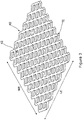
- the thinnest achievable thickness TE of a portion 40 of an expanded material currently manufactured is approximately 40 micrometers. Expanded material is produced by slitting and stretching simultaneously a material. After such a process, the material will present a plurality of pores/openings 42, which in the Fig.3 are diamond-shaped. Due to the limitations of the expansion process, this is the thinnest material achievable while still meeting the low resistivity/high conductivity and strength requirements.
- Portion 30 of perforated metallic foil 18 in this example has uniformly spaced elliptical-shaped apertures, which may be formed in the foil by mechanically punching the material or using a laser to cut or ablate the material to form the pores. It is apparent from Figs 2 and 3 that the expanded metallic material portion 40 has a greater amount of open area (defined by aggregate area of pores 42) relative to total area, AE (LE ⁇ WE), than does portion 30 of perforated metallic foil, which has less open area (defined by aggregate area of pores 32) relative to total area, A. Limiting the open area allows the perforated metallic foil 18 to be made much thinner while still achieving the required strength and resistivity characteristics.
- the open area of the perforated metallic foil 18 generally needs to be equal or below 40% of the overall surface area of the perforated metallic foil 18 in order to obtain a good compromise between weight and electrical performance.
- the perforated metallic foil 18 is also configured to provide optimal adhesive qualities so that it can be layered into and effectively embedded in resin layers such as the protective layer 19.
- good adhesion of the perforated metallic foil 18 to a composite panel 10 after a curing cycle is one that prevents substantial peeling (e.g. less than 25%) of the perforated metallic foil 18 upon application of a high water jet with the following parameters: pressure, duration, distance, sweeping angle, sweeping frequency, water temperature, maximum peeled surface.
- the values for these parameters may be defined based of the requirements of the particular application.
- the size and shape of the apertures 20 can vary has it will be explained below.
- the perforated metallic foil 18 of a composite panel 10 is submitted to a peeling force, the shearing of the surfacing film thickness occurs on top of the aperture 20 edges.
- the aperture size of the apertures 20 of the perforated metallic foil 18 are defined such that the maximum distance between two opposed points in the perimeter of an aperture 20 is comprised between 0.25 millimeters and 3 millimeters.
- the limiting factor regarding how small the apertures 20 can be made belongs to the perforation process and to its associated speed.
- apertures 20 can be made smaller, i.e. between 0.25mm and 1 mm
- the typical types of metallic material which may be used for the perforated foil are copper, aluminum, and alloys thereof.
- the plurality of apertures 20, in the aggregate define an open area of not more than 40% of the surface area.
- the weight of the perforated copper foil 18 is not more than 300 g/m 2 , preferably 115 g/m 2 .
- Such a foil 18 of 115 g/m 2 has a resistance of not more than 3.5 milliohms per square. This yields a weight to conductivity ratio of 0.40 gr-ohms. Compared with the 40 micrometers thick expanded copper foil described above, which has a 0.63 gr-ohms weight to conductivity ratio, this is over a 35% improvement.
- the plurality of apertures 20, in the aggregate define an open area of not more than 40% of the surface area.
- the weight of the perforated aluminum foil 18 may be not more than 250 g/m 2 .
- the perforated foil 18 may have a resistance of not more than 5.5 milliohms per square. This yields a weight to conductivity ratio of 0.19 gr-ohms. Compared with the 0.63 gr-ohms of the expanded copper foil, this is over a 70% improvement in the weight to conductivity ratio.
- perforated apertures and in relation with Figs. 4 to 8 , the open area in a perforated metallic foil 18 may be formed with apertures of different shapes, sizes, spacing and patterns.
- a portion 60a of a perforated metallic foil 18 is shown to include equally sized, elliptically shaped apertures 20.
- the apertures 20 may be sized as required for a particular application as long as the maximum distance between two opposed points (length A) in the perimeter of an aperture 20 is comprised between 0.25 mm and 3mm, as required to increase the tolerance to peeling.
- a 17 micrometers thick copper material having a weight of 100g/m 2 will be suitable to produce a perforated metallic foil 18 according to the invention.
- a portion 60b of a perforated metallic foil 18 is shown to include equally sized, diamond-shaped pores 20 which may be used to form a 17 micrometers thick copper foil suitable for lightning strike applications.
- a portion 60c of a perforated metallic foil 18 is shown to include equally sized, oval-shaped apertures 20 which also may be used to form a 17 micrometers thick copper foil suitable for lightning strike applications.
- the resistivity along the "X" direction versus along the "Y" direction will differ depending upon the spacing and length to height ratio of the apertures 20.
- a symmetrical pattern may be used, either in the form of circles or squares.
- a portion 70a of a perforated metallic foil 18 is shown to include equally sized, and symmetrically spaced circle-shaped apertures 20.
- a portion 70b of a perforated metallic foil 18 is shown to include equally sized, and symmetrically spaced square-shaped apertures 20.
- a method of manufacturing of the perforated metallic foil 18 includes an in-line process of perforating a metallic foil with specifically sized and spaced apertures of various geometric shapes to achieve desired performance characteristics. This could be accomplished using a perforating machine, such as machine 50 depicted in Fig. 9 .
- a wide web of thin metallic foil 52 with a thickness less than 30 micrometers, with backing material (not visible) is shown being fed under roller 54 and into the cutting dies 56.
- the backing material also helps to control tension of the metal foil 52 as it traverses through the cutting dies 56.
- the web of solid foil 52 may be processed in a reel to reel operation.
- solid metallic foil 52 with backing material may be fed into machine 50 via a pay-out reel and the web of perforated metallic foil may be received from machine and collected on a take-up reel.
- the metallic foil 52 may be pretreated to improve its durability and adhesion characteristics.
- the metallic foil 52 may be passivated, which creates an inert surface that is resistant to tarnishing and oxidation.
- the metallic foil 52 may be coated with silane, which helps to provide the material with improved adhesion characteristics.
- a perforated metallic foil 18 with a plurality of apertures 20 of a predefined geometric shape extending through the thickness of the metallic foil 52 and being distributed across a surface area may be formed.
- the aggregate amount of open area formed by the apertures 20 is configured to provide maximum conductivity while maintaining as light a weight as possible. Sizing of the apertures 20 is very important in order to maintain desired strength, conductivity, and effective adhesion properties and the following sections describe exemplary methods for designing the open area for perforated metallic foil 18 according to this invention.
- the composite panel 10 comprises a honeycomb core 12.
- the composite panel 110 is monolithic and comprises a plurality of carbon plies 116 arranged on a back side 111a of the panel 110.
- a thin perforated metallic foil 118 of identical characteristic than that of the perforated metallic foil 18 described in connection with Figs. 1 to 8 , and comprising several apertures 120, is secured to the plurality of carbon plies 116, directly, or, not according to claim 1, indirectly via an optional isolation ply 117 made of electrical insulating material, interposed between the perforated metallic foil 118 and the plurality of carbon plies 116.
- a protective layer 119 made from resin e.g. an epoxy-based resin
- a free surface of the protective layer 119 forms a top side 111b of the composite panel 110, i.e. the side of the panel 110 that when arranged on the structure of an aircraft, will form the exterior face of the skin of the aircraft and, as such, will be paint with protective and decorative paints.
- the aim of the protective layer 119 is to prevent peeling of the perforated metallic foil 118.
- the thickness of the protective layer between the top side 111a of the composite panel 10 and the metallic foil 110 is at least 15 micrometers, and preferably around 40 micrometers.
- the protective layer 119 contains a fibrous reinforcement to enhance is mechanical resistance and hence, to even reduce the tendency to peel away due to erosion causes by air flow mixed with dust and water droplets.
- This reinforcement, woven or non-woven can be in glass fibers or in carbon fibers and its areal weight is comprised between 2 to 20 g/m 2 .
- the protective layer 119 can be applied separately from the perforated metallic foil 118 (as a resin film) or it can also pre-impregnate the perforated metallic foil 118, or it could also come from resin injected or infused during the manufacturing process of the composite panel 110.
Landscapes
- Engineering & Computer Science (AREA)
- Aviation & Aerospace Engineering (AREA)
- Laminated Bodies (AREA)
Description
- This invention relates to a composite panel comprising a perforated metallic foil for lightning strike protection of an aerospace structure.
- Aluminum has been the principal material used in aircraft and aerospace construction for the past 60 years. With the growing interest to construct more efficient aircraft, manufacturers are designing more components out of light-weight composite materials. In particular, current composite panels forms the skin of the fuselage, and of the wings. Composites, however, are poor conductors of electrical current. It is know that without proper protection, composite materials are susceptible to severe damage in the event of a lightning strike. To date, aircraft manufacturers have used aluminum or copper expanded foils or woven wire mesh incorporated into these composite panels to dissipate lightning strike energy and prevent damage to the composite panel.
- Of the two approaches, expanded metallic foils have become the industry standard and are superior to woven wire as they do not unravel or have loose strands that may become problematic during processing into a pre-preg-material or when conducting a dry lay-up as part of the composite manufacturing process. The homogenous design of expanded metallic foils also ensures uncompromised conductivity even when forming the material into a variety of shapes and contours and it provides a smooth surface on the end product. Expanded metallic foils used in this application must be manufactured with tight tolerances to meet a specific weight, open area, and conductivity requirements.
- Aircraft manufactures use design guidelines, such as those set forth by SAE International in its Aerospace Recommended Practice (ARP) 5414, which defines lightning strike zones (areas of the aircraft more susceptible to lightning strikes (e.g. Zone 1A, 1B). It also provides required electrical withstand capabilities for such strike zones. For example, often materials are required to have the ability to withstand a Zone 1A strike of 200,000 amps. For expanded foils, due to the limitations of the expansion process, the thinnest material possible to meet this criteria to date has been produced using 42 micrometers foils. The weight of this material is 175 grams per square meter, the resistivity is 3.6 milliohms per square, and the foil has 56% open area. A way to characterize the performance of foils in this application is to assess the foil's weight to conductivity ratio, with conductivity being the inverse of resistivity and represented in gram-ohms (gr-ohms) per square. For the above expanded foil, its weight to conductivity ratio is 0.63 gr-ohms.
- Aircraft manufacturers are always looking for ways to increase efficiency, reduce costs, improve fuel economy, and reduce the amount of CO2 emissions. One clear way to achieve these objectives is to reduce aircraft weight. By reducing the weight of the composite panels, the overall weight of the aircraft may be reduced; however, the conductivity criteria required for specific strike zones per SAE ARP54 1 4 must still be satisfied.
- Thus, it would be desirable to produce lighter composite panels, which still meet the required electrical withstand capabilities.
- We know from the patent application
US2006/051592 , a bypass solution to the aforementioned needs. This solution consists in fixing an applique (i.e. decal) to an already manufactured composite panel in order to improve the electrical withstand capabilities of the latter. The applique comprises a metallic foil embedded in a layer made from resin and which forms the external surface of the appliqué/decal. - This solution is efficient, but attaching the applique to the panel requires several steps which must be carried out with great care and a surface treatment of the panel beforehand. Without great care when performing those steps, operators will observe rapid peeling of the applique.
- The invention aims at providing a composite panel that is, intrinsically by its manufacturing, lighter than composite panels from the prior art, and which still meet the required electrical withstand capabilities, and which is moreover resistant to erosion. To this end, the invention is directed to a composite panel for aerospace structure as claimed in claim 1.
- Embodiments of the present invention will now be described, by way of example only, with reference to the attached Figures, wherein:
-
Fig. 1 is a cross sectional view of a composite panel including a perforated metallic foil according to an aspect of this invention ; -
Fig. 2 is a perspective view of a portion of a perforated metallic foil for a composite panel as illustrated inFIG. 1 ; -
Fig. 3 is a perspective view of a portion of a prior art expanded foil; -
Fig. 4 is a plan view of a portion of the perforated metallic foil of theFig.2 having elliptical-shaped apertures; -
Fig. 5 is a plan view of a portion of a perforated metallic foil having diamond-shaped apertures; -
Fig. 6 is a plan view of a portion of a perforated metallic foil having oval-shaped apertures ; -
Fig. 7 is a plan view of a portion of a perforated metallic foil having circle-shaped apertures ; -
Fig. 8 is a plan view of a portion of a perforated metallic foil having square-shaped apertures ; -
Fig. 9 is a perspective view of a perforating machine for producing a perforated metallic foil. -
Fig. 10 is a view similar toFig.1 showing a composite panel including a perforated metallic foil according to another aspect of this invention. - In relation with the
Fig.1 , acomposite panel 10 which is, for example, used to construct the skin of the fuselage of an aircraft, comprises ahoneycomb core 12 sandwiched between a first plurality ofcarbon plies 14 and a second plurality ofcarbon plies 16. Each one of the first and second plurality ofcarbon plies honeycomb core 12 using abonding adhesive 13, such as, for example, epoxy resin. The first plurality ofcarbon plies 14 is arranged on aback side 11a of thepanel 10 which is the side of thecomposite panel 10 that is cured against a vacuum bag used during the manufacturing of thepanel 10. - According to the invention, the
composite panel 10 comprises: - a thin perforated
metallic foil 18 which hasseveral apertures 20 and is secured to a plurality of carbon plies, here the second plurality ofcarbon plies 16 on the example ofFig.1 , directly ; and - a
protective layer 19 made from resin (e.g. an epoxy-based resin) secured to the perforatedmetallic foil 18, with the perforatedmetallic foil 18 being embedded in theprotective layer 19 through itsapertures 20. A free surface of theprotective layer 19 forms thetop side 11b of thecomposite panel 10, i.e. the side of thepanel 10 that when arranged on the structure of an aircraft, will form the exterior face of the skin of the aircraft and, as such, will be paint with protective and decorative paints. - In an embodiment which is not part of the claimed invention, the thin perforated
metallic foil 18 is secured to a plurality of carbon plies, here the second plurality ofcarbon plies 16 indirectly via anoptional isolation ply 17 made of electrical insulating material, interposed between the perforatedmetallic foil 18 and the plurality of carbon plies. - One particular aim of the
protective layer 19 is to prevent peeling of the perforatedmetallic foil 18. To this end, the thickness of the protective layer between thetop side 11a of thecomposite panel 10 and themetallic foil 10 is at least 15 micrometers, and preferably around 40 micrometers. According to claim 1, theprotective layer 19 contains a fibrous reinforcement to enhance is mechanical resistance and hence, to even reduce the tendency to peel away due to erosion causes by air flow mixed with dust and water droplets. This reinforcement, woven or non-woven can be in glass fibers or in carbon fibers and its areal weight is comprised between 2 to 20 g/m2. - During the manufacturing process of the
composite panel 10, theprotective layer 19 pre-impregnates the perforatedmetallic foil 18, or, in a variant, comes from resin injected or infused during the manufacturing process of thecomposite panel 10. - In any case, the areal weight of the
surfacing film 19 is comprised between 20 and 200g/m2. - The perforated
metallic foil 18 is designed to have a very low weight to conductivity ratio and with these characteristics the perforatedmetallic foil 18 is used to protect an aircraft whose external skin is formed bycomposite panel 10 according to the invention from lightning strikes of a significant magnitude (e.g. Zone 1A strikes of 200,000 amps or more), while allowing the aircraft manufacturer to produce a lighter weight and more efficient aircraft. - Referring to
Fig. 2 , a perspective view of aportion 30 of perforatedmetallic foil 18 having circular-shaped apertures 20 is shown.Portion 30 of the perforatedmetallic foil 18 is shown to have a length, L, and a width, W, which define a surface area, A, of L∗W. Distributed across surface area A are a plurality ofapertures 20, which extend through the thickness, T, of the perforatedmetallic foil 18. - The thickness T is no more than 30 micrometers in order to limit the weight of
composite panel 10 . For comparison, and in relation withFig.3 , the thinnest achievable thickness TE of aportion 40 of an expanded material currently manufactured is approximately 40 micrometers. Expanded material is produced by slitting and stretching simultaneously a material. After such a process, the material will present a plurality of pores/openings 42, which in theFig.3 are diamond-shaped. Due to the limitations of the expansion process, this is the thinnest material achievable while still meeting the low resistivity/high conductivity and strength requirements. - Thinner metallic perforated
foils 18 are achievable; however, the apertures size and spacing, as well as the amount of open area relative to total foil area must be optimized to achieve desired weight, strength, adhesion capability, and conductivity.Portion 30 of perforatedmetallic foil 18 in this example has uniformly spaced elliptical-shaped apertures, which may be formed in the foil by mechanically punching the material or using a laser to cut or ablate the material to form the pores. It is apparent fromFigs 2 and3 that the expandedmetallic material portion 40 has a greater amount of open area (defined by aggregate area of pores 42) relative to total area, AE (LE ∗WE), than doesportion 30 of perforated metallic foil, which has less open area (defined by aggregate area of pores 32) relative to total area, A. Limiting the open area allows the perforatedmetallic foil 18 to be made much thinner while still achieving the required strength and resistivity characteristics. - The open area of the perforated
metallic foil 18 generally needs to be equal or below 40% of the overall surface area of the perforatedmetallic foil 18 in order to obtain a good compromise between weight and electrical performance. - The perforated
metallic foil 18 is also configured to provide optimal adhesive qualities so that it can be layered into and effectively embedded in resin layers such as theprotective layer 19. For purposes of our description, good adhesion of the perforatedmetallic foil 18 to acomposite panel 10 after a curing cycle is one that prevents substantial peeling (e.g. less than 25%) of the perforatedmetallic foil 18 upon application of a high water jet with the following parameters: pressure, duration, distance, sweeping angle, sweeping frequency, water temperature, maximum peeled surface. The values for these parameters may be defined based of the requirements of the particular application. - It is desired to maximize the open area to allow the perforated
metallic foil 18 to be stretched and hence to be applied on surfaces having double curvatures as could be thecomposite panel 10 to form an aircraft skin. The size and shape of theapertures 20 can vary has it will be explained below. However, when the perforatedmetallic foil 18 of acomposite panel 10 is submitted to a peeling force, the shearing of the surfacing film thickness occurs on top of theaperture 20 edges. Thus, to reduce the shearing constrain encountered by theprotective layer 19 and hence to increase the tolerance to peeling, it is advantageous to maximize the sum of the perimeters of all theapertures 20 per surface unit. For a given aperture rate, this is obtained by reducing both the aperture size and their pitch. Hence, the aperture size of theapertures 20 of the perforatedmetallic foil 18 are defined such that the maximum distance between two opposed points in the perimeter of anaperture 20 is comprised between 0.25 millimeters and 3 millimeters. - The limiting factor regarding how small the
apertures 20 can be made belongs to the perforation process and to its associated speed. - In case perforations are made by mechanical puncturing/perforation (e.g. die-based perforation), the capability to manufacture small punches and the capability of the puncturing machine will limit the minimum size of the
apertures 20. It has been found thatapertures 20 having a dimension of 1mm was close to the realistic limit. - In case perforations are made by laser etching,
apertures 20 can be made smaller, i.e. between 0.25mm and 1 mm - Taking into account the ability of the perforated
metallic foil 18 to be stretched, the peeling tolerance, and the constrain coming from perforation process, a pattern achieved withapertures 20 having a dimension around 1mm and an open area around 30% has been found to be convenient. - The typical types of metallic material which may be used for the perforated foil are copper, aluminum, and alloys thereof.
- For a copper or copper alloy perforated
foil 18, the plurality ofapertures 20, in the aggregate, define an open area of not more than 40% of the surface area. The weight of the perforatedcopper foil 18 is not more than 300 g/m2 , preferably 115 g/m2. Such afoil 18 of 115 g/m2 has a resistance of not more than 3.5 milliohms per square. This yields a weight to conductivity ratio of 0.40 gr-ohms. Compared with the 40 micrometers thick expanded copper foil described above, which has a 0.63 gr-ohms weight to conductivity ratio, this is over a 35% improvement. With the perforatedmetallic foil 18 and processing used herein, it is expected that copper or copper alloy foils 18 as thin as approximately 12 micrometers would be achievable with comparable weight to conductivity ratios. - For an aluminum or aluminum alloy perforated
foil 18 herein, the plurality ofapertures 20, in the aggregate, define an open area of not more than 40% of the surface area. The weight of theperforated aluminum foil 18 may be not more than 250 g/m2. Theperforated foil 18 may have a resistance of not more than 5.5 milliohms per square. This yields a weight to conductivity ratio of 0.19 gr-ohms. Compared with the 0.63 gr-ohms of the expanded copper foil, this is over a 70% improvement in the weight to conductivity ratio. With the perforatedmetallic foil 18 and processing used herein, it is expected that aluminum or aluminum alloy foils as thin as approximately 12 micrometers would also be achievable with comparable weight to conductivity ratios. - Historically, lightning strike applications have primarily utilized either a woven material, which yields a square pattern, or expanded material, which yields a diamond or hexagonal shapes. By using perforated apertures, and in relation with
Figs. 4 to 8 , the open area in a perforatedmetallic foil 18 may be formed with apertures of different shapes, sizes, spacing and patterns. - The most efficient shapes, in terms of electric field lines, are rounded, as sharp corners that are necessarily prevalent in woven or expanded materials create higher flux density in the areas of the sharp corners. These higher flux areas naturally increase the measured resistivity of the material.
- Referring to
Fig 4 , aportion 60a of a perforatedmetallic foil 18 is shown to include equally sized, elliptically shapedapertures 20. Theapertures 20 may be sized as required for a particular application as long as the maximum distance between two opposed points (length A) in the perimeter of anaperture 20 is comprised between 0.25 mm and 3mm, as required to increase the tolerance to peeling. - The open area of material may be determined by the following equation:

- As an example, taking a desired weight of 100 grams per square meter (gsm) and using 17 micrometers thick copper as the desired material, which has a density of 8.89 x 10⁶ g/m3, the open area is determined to be:

- A 17 micrometers thick copper material having a weight of 100g/m2 will be suitable to produce a perforated
metallic foil 18 according to the invention. - Once the targeted open area, apertures size and shape are selected, the spacing of the apertures can be determined to achieve the resulting configuration. Carrying on with the example above, for an elliptical shape apertures, calculations are as follows:


- Referring to
Fig.5 aportion 60b of a perforatedmetallic foil 18 is shown to include equally sized, diamond-shapedpores 20 which may be used to form a 17 micrometers thick copper foil suitable for lightning strike applications. Referring toFig.6 , aportion 60c of a perforatedmetallic foil 18 is shown to include equally sized, oval-shapedapertures 20 which also may be used to form a 17 micrometers thick copper foil suitable for lightning strike applications. - Using ellipses, ovals or diamond shape apertures, as shown in
Figs. 4 to 6 , can be beneficial to obtain a material with fine-tuned anisotropy in term of electrical resistance. The resistivity along the "X" direction versus along the "Y" direction will differ depending upon the spacing and length to height ratio of theapertures 20. It is sometimes desired to utilize a perforatedmetallic foil 18 with conductive properties that are approximately equal in all directions, i.e. "isotropic". To achieve isotropic features for conductivity, a symmetrical pattern may be used, either in the form of circles or squares. - Referring to
Fig.7 , aportion 70a of a perforatedmetallic foil 18 is shown to include equally sized, and symmetrically spaced circle-shapedapertures 20. Referring toFig.8 , aportion 70b of a perforatedmetallic foil 18 is shown to include equally sized, and symmetrically spaced square-shapedapertures 20. - Although not illustrated other shapes for the
apertures 20, e.g. polygonal, are possible in order to meet the need for particular electrical resistance of the perforatedmetallic foil 18. - A method of manufacturing of the perforated
metallic foil 18 includes an in-line process of perforating a metallic foil with specifically sized and spaced apertures of various geometric shapes to achieve desired performance characteristics. This could be accomplished using a perforating machine, such asmachine 50 depicted inFig. 9 . - According to this manufacturing method, a wide web of thin
metallic foil 52 with a thickness less than 30 micrometers, with backing material (not visible) is shown being fed underroller 54 and into the cutting dies 56. The backing material also helps to control tension of themetal foil 52 as it traverses through the cutting dies 56. While not shown in this view, the web ofsolid foil 52 may be processed in a reel to reel operation. In other words, solidmetallic foil 52 with backing material may be fed intomachine 50 via a pay-out reel and the web of perforated metallic foil may be received from machine and collected on a take-up reel. - The
metallic foil 52 may be pretreated to improve its durability and adhesion characteristics. In addition, themetallic foil 52 may be passivated, which creates an inert surface that is resistant to tarnishing and oxidation. Also, themetallic foil 52 may be coated with silane, which helps to provide the material with improved adhesion characteristics. - By perforating the thin
metallic foil 52, it is obtained a perforatedmetallic foil 18 with a plurality ofapertures 20 of a predefined geometric shape extending through the thickness of themetallic foil 52 and being distributed across a surface area may be formed. The aggregate amount of open area formed by theapertures 20 is configured to provide maximum conductivity while maintaining as light a weight as possible. Sizing of theapertures 20 is very important in order to maintain desired strength, conductivity, and effective adhesion properties and the following sections describe exemplary methods for designing the open area for perforatedmetallic foil 18 according to this invention. - An alternate approach (not illustrated) to using a mechanical die-based perforating machine, such as
machine 50, would be to use a reel-to-reel galvanometric laser to accomplish the precision cutting/ablating to manufacture the metallic foils according to an aspect of this invention. - The invention has been described above when the
composite panel 10 comprises ahoneycomb core 12. In another variant of the invention, and in relation with theFig. 10 , thecomposite panel 110 is monolithic and comprises a plurality of carbon plies 116 arranged on a back side 111a of thepanel 110. - A thin perforated
metallic foil 118, of identical characteristic than that of the perforatedmetallic foil 18 described in connection withFigs. 1 to 8 , and comprisingseveral apertures 120, is secured to the plurality of carbon plies 116, directly, or, not according to claim 1, indirectly via an optional isolation ply 117 made of electrical insulating material, interposed between the perforatedmetallic foil 118 and the plurality of carbon plies 116. Finally, aprotective layer 119 made from resin (e.g. an epoxy-based resin) is secured to the perforatedmetallic foil 118, with the perforatedmetallic foil 118 being embedded in theprotective layer 119 through itsapertures 120. A free surface of theprotective layer 119 forms atop side 111b of thecomposite panel 110, i.e. the side of thepanel 110 that when arranged on the structure of an aircraft, will form the exterior face of the skin of the aircraft and, as such, will be paint with protective and decorative paints. - The aim of the
protective layer 119 is to prevent peeling of the perforatedmetallic foil 118. To this end, the thickness of the protective layer between the top side 111a of thecomposite panel 10 and themetallic foil 110 is at least 15 micrometers, and preferably around 40 micrometers. According to claim 1, theprotective layer 119 contains a fibrous reinforcement to enhance is mechanical resistance and hence, to even reduce the tendency to peel away due to erosion causes by air flow mixed with dust and water droplets. This reinforcement, woven or non-woven can be in glass fibers or in carbon fibers and its areal weight is comprised between 2 to 20 g/m2. - During the manufacturing process of the
composite panel 110, theprotective layer 119 can be applied separately from the perforated metallic foil 118 (as a resin film) or it can also pre-impregnate the perforatedmetallic foil 118, or it could also come from resin injected or infused during the manufacturing process of thecomposite panel 110.
Claims (6)
- A composite panel (10,110) for an aerospace structure, comprising a plurality of carbon plies (16, 116), a perforated metallic foil (18,118) comprising several apertures (20, 120) directly secured to the plurality of carbon plies (16,116), and a protective layer (19,119) made from resin containing a fibrous reinforcement whose areal weight is comprised between 2 to 20 g/m2, said protective layer (19, 119) being secured to the metallic foil (18,118) with the perforated metallic foil (18,118) being embedded in the protective layer (19,119) through its apertures (20,120), a free surface of the protective layer forming a top side (11b,111b) of the composite panel (10,110), the thickness of the protective layer (19,119) between the top side (11b,111b) of the composite panel (10,110) and the perforated metallic foil (18,118) being at least 15 micrometers and the perforated metallic foil (18,110) has a thickness of not more than 30 micrometers, the apertures having a predefined geometric shape extending through the thickness (T) of the perforated metallic foil (18,118) and being distributed across a surface area defined by the length (L) and the width (W) of the perforated metallic foil (18,118), the plurality of apertures (20,120) in the aggregate defining an open area of not more than 40% of the surface area and the maximum distance between two opposed points in the perimeter of an aperture (20) being equal or less than 3 mm.
- A composite panel (10) according to claim 1, characterized in that the perforated metallic foil (18) is made from copper or a copper alloy and has a weight of not more than 300 g/m2 and a weight to conductivity ratio of not more than 0.40 gram-ohms per square.
- A composite panel (10) according to claim 1, characterized in that the perforated metallic foil (18) is made from aluminum or an aluminum alloy and has a weight of not more than 250 g/m2 and a weight to conductivity ratio of not more than 0.19 gram-ohms per square.
- A composite panel (10) according to any one of the claims 1 to 3, wherein the predefined geometric shape of the plurality of apertures (20) is circular.
- A composite panel (10) according to any one of the claims 1 to 3, wherein the predefined geometric shape of the plurality of apertures (20) is non-circular.
- A composite panel (10) according to claim 5, wherein the predefined geometric shape of the plurality of apertures (20) is one among elliptical, diamond, oval, and square.
Applications Claiming Priority (3)
| Application Number | Priority Date | Filing Date | Title |
|---|---|---|---|
| US15/973,905 US10351259B2 (en) | 2018-05-08 | 2018-05-08 | Ultra-thin metallic foil for lightning strike protection |
| EP18382370.7A EP3575222A1 (en) | 2018-05-30 | 2018-05-30 | Lightning protection for aircrafts and method for its manufacturing |
| PCT/EP2019/059744 WO2019214910A1 (en) | 2018-05-08 | 2019-04-16 | Composite panel comprising a perforated metallic foil for lightning strike protection and a perforated metallic foil |
Publications (2)
| Publication Number | Publication Date |
|---|---|
| EP3790803A1 EP3790803A1 (en) | 2021-03-17 |
| EP3790803B1 true EP3790803B1 (en) | 2022-08-17 |
Family
ID=66218110
Family Applications (1)
| Application Number | Title | Priority Date | Filing Date |
|---|---|---|---|
| EP19718162.1A Active EP3790803B1 (en) | 2018-05-08 | 2019-04-16 | Composite panel comprising a perforated metallic foil for lightning strike protection |
Country Status (3)
| Country | Link |
|---|---|
| EP (1) | EP3790803B1 (en) |
| CN (1) | CN112041231B (en) |
| WO (1) | WO2019214910A1 (en) |
Families Citing this family (1)
| Publication number | Priority date | Publication date | Assignee | Title |
|---|---|---|---|---|
| LU102368B1 (en) * | 2020-12-31 | 2022-06-30 | Luxembourg Inst Science & Tech List | Lightning strike protection material and Structure |
Family Cites Families (10)
| Publication number | Priority date | Publication date | Assignee | Title |
|---|---|---|---|---|
| US5127601A (en) * | 1989-01-23 | 1992-07-07 | Lightning Diversion Systems | Conformal lightning shield and method of making |
| US5370921A (en) * | 1991-07-11 | 1994-12-06 | The Dexter Corporation | Lightning strike composite and process |
| US7867621B2 (en) * | 2003-09-30 | 2011-01-11 | The Boeing Company | Wide area lightning diverter overlay |
| US8962130B2 (en) * | 2006-03-10 | 2015-02-24 | Rohr, Inc. | Low density lightning strike protection for use in airplanes |
| US7599164B2 (en) * | 2006-12-07 | 2009-10-06 | The Boeing Company | Lightning protection system for aircraft composite structure |
| US8206823B2 (en) * | 2008-04-14 | 2012-06-26 | The Boeing Company | System and method for fabrication of integrated lightning strike protection material |
| US20100147546A1 (en) * | 2008-12-11 | 2010-06-17 | Kenneth Mull | Expanded metal lightning protection foils with isotropic electrical resistance |
| FR2939715B1 (en) * | 2008-12-15 | 2012-11-16 | Eads Europ Aeronautic Defence | PIECE OF COMPOSITE MATERIAL INCLUDING MEANS OF PROTECTION AGAINST LIGHTNING |
| US9708075B2 (en) * | 2011-04-21 | 2017-07-18 | The United States Of America As Represented By The Administrator Of The National Aeronautics And Space Administration | Lightning protection and detection system |
| US20130271891A1 (en) * | 2012-04-13 | 2013-10-17 | Dexmet Corporation | Metallic Mesh and Lightning Strike Protection System |
-
2019
- 2019-04-16 WO PCT/EP2019/059744 patent/WO2019214910A1/en not_active Ceased
- 2019-04-16 CN CN201980029375.1A patent/CN112041231B/en active Active
- 2019-04-16 EP EP19718162.1A patent/EP3790803B1/en active Active
Also Published As
| Publication number | Publication date |
|---|---|
| EP3790803A1 (en) | 2021-03-17 |
| WO2019214910A1 (en) | 2019-11-14 |
| CN112041231A (en) | 2020-12-04 |
| CN112041231B (en) | 2025-12-23 |
Similar Documents
| Publication | Publication Date | Title |
|---|---|---|
| US11518541B2 (en) | Composite panel comprising a perforated metallic foil for lightning strike protection and a perforated metallic foil | |
| EP2660463B1 (en) | Wind turbine blades | |
| EP1238572B1 (en) | A thermoplastic laminate fabric heater and methods for making same | |
| US8636936B2 (en) | Method for fabricating a laminated fiber metal composite | |
| JP6195112B2 (en) | Mechanical reinforcement for composite parts, especially large wind turbine propellers | |
| WO2020128793A1 (en) | Fiber-reinforced composite layup | |
| JP7161989B2 (en) | Protective film | |
| JP2011524265A5 (en) | ||
| CN112041231B (en) | Composite panel comprising perforated metal foil for lightning strike protection | |
| CA2546728C (en) | Sandwich panel core | |
| EP4659926A1 (en) | Core material sheet, composite material, method for manufacturing core material sheet, and method for manufacturing composite material | |
| JP6685752B2 (en) | Laminated plate and method of processing laminated plate | |
| CN220202323U (en) | Composite mica paper convenient to cut | |
| EP3575222A1 (en) | Lightning protection for aircrafts and method for its manufacturing | |
| JP2021138125A (en) | Tape and its manufacturing method |
Legal Events
| Date | Code | Title | Description |
|---|---|---|---|
| STAA | Information on the status of an ep patent application or granted ep patent |
Free format text: STATUS: UNKNOWN |
|
| STAA | Information on the status of an ep patent application or granted ep patent |
Free format text: STATUS: THE INTERNATIONAL PUBLICATION HAS BEEN MADE |
|
| PUAI | Public reference made under article 153(3) epc to a published international application that has entered the european phase |
Free format text: ORIGINAL CODE: 0009012 |
|
| STAA | Information on the status of an ep patent application or granted ep patent |
Free format text: STATUS: REQUEST FOR EXAMINATION WAS MADE |
|
| 17P | Request for examination filed |
Effective date: 20201208 |
|
| AK | Designated contracting states |
Kind code of ref document: A1 Designated state(s): AL AT BE BG CH CY CZ DE DK EE ES FI FR GB GR HR HU IE IS IT LI LT LU LV MC MK MT NL NO PL PT RO RS SE SI SK SM TR |
|
| AX | Request for extension of the european patent |
Extension state: BA ME |
|
| DAV | Request for validation of the european patent (deleted) | ||
| DAX | Request for extension of the european patent (deleted) | ||
| REG | Reference to a national code |
Ref country code: DE Ref legal event code: R079 Ref document number: 602019018379 Country of ref document: DE Free format text: PREVIOUS MAIN CLASS: B64D0045020000 Ipc: B32B0003120000 |
|
| GRAP | Despatch of communication of intention to grant a patent |
Free format text: ORIGINAL CODE: EPIDOSNIGR1 |
|
| STAA | Information on the status of an ep patent application or granted ep patent |
Free format text: STATUS: GRANT OF PATENT IS INTENDED |
|
| RIC1 | Information provided on ipc code assigned before grant |
Ipc: H02G 13/00 20060101ALI20220406BHEP Ipc: B32B 3/26 20060101ALI20220406BHEP Ipc: B64D 45/02 20060101ALI20220406BHEP Ipc: B32B 15/20 20060101ALI20220406BHEP Ipc: B32B 15/14 20060101ALI20220406BHEP Ipc: B32B 15/092 20060101ALI20220406BHEP Ipc: B32B 7/12 20060101ALI20220406BHEP Ipc: B32B 5/26 20060101ALI20220406BHEP Ipc: B32B 3/12 20060101AFI20220406BHEP |
|
| INTG | Intention to grant announced |
Effective date: 20220426 |
|
| GRAS | Grant fee paid |
Free format text: ORIGINAL CODE: EPIDOSNIGR3 |
|
| GRAA | (expected) grant |
Free format text: ORIGINAL CODE: 0009210 |
|
| STAA | Information on the status of an ep patent application or granted ep patent |
Free format text: STATUS: THE PATENT HAS BEEN GRANTED |
|
| AK | Designated contracting states |
Kind code of ref document: B1 Designated state(s): AL AT BE BG CH CY CZ DE DK EE ES FI FR GB GR HR HU IE IS IT LI LT LU LV MC MK MT NL NO PL PT RO RS SE SI SK SM TR |
|
| REG | Reference to a national code |
Ref country code: CH Ref legal event code: EP |
|
| REG | Reference to a national code |
Ref country code: DE Ref legal event code: R096 Ref document number: 602019018379 Country of ref document: DE |
|
| REG | Reference to a national code |
Ref country code: IE Ref legal event code: FG4D |
|
| REG | Reference to a national code |
Ref country code: AT Ref legal event code: REF Ref document number: 1511920 Country of ref document: AT Kind code of ref document: T Effective date: 20220915 |
|
| REG | Reference to a national code |
Ref country code: NL Ref legal event code: MP Effective date: 20220817 |
|
| REG | Reference to a national code |
Ref country code: LT Ref legal event code: MG9D |
|
| PG25 | Lapsed in a contracting state [announced via postgrant information from national office to epo] |
Ref country code: SE Free format text: LAPSE BECAUSE OF FAILURE TO SUBMIT A TRANSLATION OF THE DESCRIPTION OR TO PAY THE FEE WITHIN THE PRESCRIBED TIME-LIMIT Effective date: 20220817 Ref country code: RS Free format text: LAPSE BECAUSE OF FAILURE TO SUBMIT A TRANSLATION OF THE DESCRIPTION OR TO PAY THE FEE WITHIN THE PRESCRIBED TIME-LIMIT Effective date: 20220817 Ref country code: PT Free format text: LAPSE BECAUSE OF FAILURE TO SUBMIT A TRANSLATION OF THE DESCRIPTION OR TO PAY THE FEE WITHIN THE PRESCRIBED TIME-LIMIT Effective date: 20221219 Ref country code: NO Free format text: LAPSE BECAUSE OF FAILURE TO SUBMIT A TRANSLATION OF THE DESCRIPTION OR TO PAY THE FEE WITHIN THE PRESCRIBED TIME-LIMIT Effective date: 20221117 Ref country code: NL Free format text: LAPSE BECAUSE OF FAILURE TO SUBMIT A TRANSLATION OF THE DESCRIPTION OR TO PAY THE FEE WITHIN THE PRESCRIBED TIME-LIMIT Effective date: 20220817 Ref country code: LV Free format text: LAPSE BECAUSE OF FAILURE TO SUBMIT A TRANSLATION OF THE DESCRIPTION OR TO PAY THE FEE WITHIN THE PRESCRIBED TIME-LIMIT Effective date: 20220817 Ref country code: LT Free format text: LAPSE BECAUSE OF FAILURE TO SUBMIT A TRANSLATION OF THE DESCRIPTION OR TO PAY THE FEE WITHIN THE PRESCRIBED TIME-LIMIT Effective date: 20220817 Ref country code: FI Free format text: LAPSE BECAUSE OF FAILURE TO SUBMIT A TRANSLATION OF THE DESCRIPTION OR TO PAY THE FEE WITHIN THE PRESCRIBED TIME-LIMIT Effective date: 20220817 |
|
| REG | Reference to a national code |
Ref country code: AT Ref legal event code: MK05 Ref document number: 1511920 Country of ref document: AT Kind code of ref document: T Effective date: 20220817 |
|
| PG25 | Lapsed in a contracting state [announced via postgrant information from national office to epo] |
Ref country code: PL Free format text: LAPSE BECAUSE OF FAILURE TO SUBMIT A TRANSLATION OF THE DESCRIPTION OR TO PAY THE FEE WITHIN THE PRESCRIBED TIME-LIMIT Effective date: 20220817 Ref country code: IS Free format text: LAPSE BECAUSE OF FAILURE TO SUBMIT A TRANSLATION OF THE DESCRIPTION OR TO PAY THE FEE WITHIN THE PRESCRIBED TIME-LIMIT Effective date: 20221217 Ref country code: HR Free format text: LAPSE BECAUSE OF FAILURE TO SUBMIT A TRANSLATION OF THE DESCRIPTION OR TO PAY THE FEE WITHIN THE PRESCRIBED TIME-LIMIT Effective date: 20220817 Ref country code: GR Free format text: LAPSE BECAUSE OF FAILURE TO SUBMIT A TRANSLATION OF THE DESCRIPTION OR TO PAY THE FEE WITHIN THE PRESCRIBED TIME-LIMIT Effective date: 20221118 |
|
| PG25 | Lapsed in a contracting state [announced via postgrant information from national office to epo] |
Ref country code: SM Free format text: LAPSE BECAUSE OF FAILURE TO SUBMIT A TRANSLATION OF THE DESCRIPTION OR TO PAY THE FEE WITHIN THE PRESCRIBED TIME-LIMIT Effective date: 20220817 Ref country code: RO Free format text: LAPSE BECAUSE OF FAILURE TO SUBMIT A TRANSLATION OF THE DESCRIPTION OR TO PAY THE FEE WITHIN THE PRESCRIBED TIME-LIMIT Effective date: 20220817 Ref country code: ES Free format text: LAPSE BECAUSE OF FAILURE TO SUBMIT A TRANSLATION OF THE DESCRIPTION OR TO PAY THE FEE WITHIN THE PRESCRIBED TIME-LIMIT Effective date: 20220817 Ref country code: DK Free format text: LAPSE BECAUSE OF FAILURE TO SUBMIT A TRANSLATION OF THE DESCRIPTION OR TO PAY THE FEE WITHIN THE PRESCRIBED TIME-LIMIT Effective date: 20220817 Ref country code: CZ Free format text: LAPSE BECAUSE OF FAILURE TO SUBMIT A TRANSLATION OF THE DESCRIPTION OR TO PAY THE FEE WITHIN THE PRESCRIBED TIME-LIMIT Effective date: 20220817 Ref country code: AT Free format text: LAPSE BECAUSE OF FAILURE TO SUBMIT A TRANSLATION OF THE DESCRIPTION OR TO PAY THE FEE WITHIN THE PRESCRIBED TIME-LIMIT Effective date: 20220817 |
|
| REG | Reference to a national code |
Ref country code: DE Ref legal event code: R097 Ref document number: 602019018379 Country of ref document: DE |
|
| PG25 | Lapsed in a contracting state [announced via postgrant information from national office to epo] |
Ref country code: SK Free format text: LAPSE BECAUSE OF FAILURE TO SUBMIT A TRANSLATION OF THE DESCRIPTION OR TO PAY THE FEE WITHIN THE PRESCRIBED TIME-LIMIT Effective date: 20220817 Ref country code: EE Free format text: LAPSE BECAUSE OF FAILURE TO SUBMIT A TRANSLATION OF THE DESCRIPTION OR TO PAY THE FEE WITHIN THE PRESCRIBED TIME-LIMIT Effective date: 20220817 |
|
| PLBE | No opposition filed within time limit |
Free format text: ORIGINAL CODE: 0009261 |
|
| STAA | Information on the status of an ep patent application or granted ep patent |
Free format text: STATUS: NO OPPOSITION FILED WITHIN TIME LIMIT |
|
| PG25 | Lapsed in a contracting state [announced via postgrant information from national office to epo] |
Ref country code: AL Free format text: LAPSE BECAUSE OF FAILURE TO SUBMIT A TRANSLATION OF THE DESCRIPTION OR TO PAY THE FEE WITHIN THE PRESCRIBED TIME-LIMIT Effective date: 20220817 |
|
| 26N | No opposition filed |
Effective date: 20230519 |
|
| PG25 | Lapsed in a contracting state [announced via postgrant information from national office to epo] |
Ref country code: SI Free format text: LAPSE BECAUSE OF FAILURE TO SUBMIT A TRANSLATION OF THE DESCRIPTION OR TO PAY THE FEE WITHIN THE PRESCRIBED TIME-LIMIT Effective date: 20220817 |
|
| PG25 | Lapsed in a contracting state [announced via postgrant information from national office to epo] |
Ref country code: LU Free format text: LAPSE BECAUSE OF NON-PAYMENT OF DUE FEES Effective date: 20230416 |
|
| REG | Reference to a national code |
Ref country code: BE Ref legal event code: MM Effective date: 20230430 |
|
| PG25 | Lapsed in a contracting state [announced via postgrant information from national office to epo] |
Ref country code: MC Free format text: LAPSE BECAUSE OF FAILURE TO SUBMIT A TRANSLATION OF THE DESCRIPTION OR TO PAY THE FEE WITHIN THE PRESCRIBED TIME-LIMIT Effective date: 20220817 |
|
| PG25 | Lapsed in a contracting state [announced via postgrant information from national office to epo] |
Ref country code: MC Free format text: LAPSE BECAUSE OF FAILURE TO SUBMIT A TRANSLATION OF THE DESCRIPTION OR TO PAY THE FEE WITHIN THE PRESCRIBED TIME-LIMIT Effective date: 20220817 |
|
| REG | Reference to a national code |
Ref country code: IE Ref legal event code: MM4A |
|
| PG25 | Lapsed in a contracting state [announced via postgrant information from national office to epo] |
Ref country code: BE Free format text: LAPSE BECAUSE OF NON-PAYMENT OF DUE FEES Effective date: 20230430 |
|
| PG25 | Lapsed in a contracting state [announced via postgrant information from national office to epo] |
Ref country code: IE Free format text: LAPSE BECAUSE OF NON-PAYMENT OF DUE FEES Effective date: 20230416 |
|
| PG25 | Lapsed in a contracting state [announced via postgrant information from national office to epo] |
Ref country code: IE Free format text: LAPSE BECAUSE OF NON-PAYMENT OF DUE FEES Effective date: 20230416 |
|
| PG25 | Lapsed in a contracting state [announced via postgrant information from national office to epo] |
Ref country code: IT Free format text: LAPSE BECAUSE OF FAILURE TO SUBMIT A TRANSLATION OF THE DESCRIPTION OR TO PAY THE FEE WITHIN THE PRESCRIBED TIME-LIMIT Effective date: 20220817 |
|
| PG25 | Lapsed in a contracting state [announced via postgrant information from national office to epo] |
Ref country code: BG Free format text: LAPSE BECAUSE OF FAILURE TO SUBMIT A TRANSLATION OF THE DESCRIPTION OR TO PAY THE FEE WITHIN THE PRESCRIBED TIME-LIMIT Effective date: 20220817 |
|
| PG25 | Lapsed in a contracting state [announced via postgrant information from national office to epo] |
Ref country code: BG Free format text: LAPSE BECAUSE OF FAILURE TO SUBMIT A TRANSLATION OF THE DESCRIPTION OR TO PAY THE FEE WITHIN THE PRESCRIBED TIME-LIMIT Effective date: 20220817 |
|
| PGFP | Annual fee paid to national office [announced via postgrant information from national office to epo] |
Ref country code: DE Payment date: 20250422 Year of fee payment: 7 |
|
| PGFP | Annual fee paid to national office [announced via postgrant information from national office to epo] |
Ref country code: GB Payment date: 20250423 Year of fee payment: 7 |
|
| PGFP | Annual fee paid to national office [announced via postgrant information from national office to epo] |
Ref country code: FR Payment date: 20250425 Year of fee payment: 7 |
|
| PGFP | Annual fee paid to national office [announced via postgrant information from national office to epo] |
Ref country code: CH Payment date: 20250501 Year of fee payment: 7 |
|
| PG25 | Lapsed in a contracting state [announced via postgrant information from national office to epo] |
Ref country code: CY Free format text: LAPSE BECAUSE OF FAILURE TO SUBMIT A TRANSLATION OF THE DESCRIPTION OR TO PAY THE FEE WITHIN THE PRESCRIBED TIME-LIMIT; INVALID AB INITIO Effective date: 20190416 |
|
| PG25 | Lapsed in a contracting state [announced via postgrant information from national office to epo] |
Ref country code: HU Free format text: LAPSE BECAUSE OF FAILURE TO SUBMIT A TRANSLATION OF THE DESCRIPTION OR TO PAY THE FEE WITHIN THE PRESCRIBED TIME-LIMIT; INVALID AB INITIO Effective date: 20190416 |
|
| PG25 | Lapsed in a contracting state [announced via postgrant information from national office to epo] |
Ref country code: TR Free format text: LAPSE BECAUSE OF FAILURE TO SUBMIT A TRANSLATION OF THE DESCRIPTION OR TO PAY THE FEE WITHIN THE PRESCRIBED TIME-LIMIT Effective date: 20220817 |
|
| REG | Reference to a national code |
Ref country code: CH Ref legal event code: U11 Free format text: ST27 STATUS EVENT CODE: U-0-0-U10-U11 (AS PROVIDED BY THE NATIONAL OFFICE) Effective date: 20260501 |