EP3790184A1 - Electric stapler - Google Patents
Electric stapler Download PDFInfo
- Publication number
- EP3790184A1 EP3790184A1 EP20195229.8A EP20195229A EP3790184A1 EP 3790184 A1 EP3790184 A1 EP 3790184A1 EP 20195229 A EP20195229 A EP 20195229A EP 3790184 A1 EP3790184 A1 EP 3790184A1
- Authority
- EP
- European Patent Office
- Prior art keywords
- electric stapler
- motor
- control unit
- binding
- processing apparatus
- Prior art date
- Legal status (The legal status is an assumption and is not a legal conclusion. Google has not performed a legal analysis and makes no representation as to the accuracy of the status listed.)
- Withdrawn
Links
Images


Classifications
-
- H—ELECTRICITY
- H02—GENERATION; CONVERSION OR DISTRIBUTION OF ELECTRIC POWER
- H02P—CONTROL OR REGULATION OF ELECTRIC MOTORS, ELECTRIC GENERATORS OR DYNAMO-ELECTRIC CONVERTERS; CONTROLLING TRANSFORMERS, REACTORS OR CHOKE COILS
- H02P6/00—Arrangements for controlling synchronous motors or other dynamo-electric motors using electronic commutation dependent on the rotor position; Electronic commutators therefor
- H02P6/28—Arrangements for controlling current
-
- B—PERFORMING OPERATIONS; TRANSPORTING
- B27—WORKING OR PRESERVING WOOD OR SIMILAR MATERIAL; NAILING OR STAPLING MACHINES IN GENERAL
- B27F—DOVETAILED WORK; TENONS; SLOTTING MACHINES FOR WOOD OR SIMILAR MATERIAL; NAILING OR STAPLING MACHINES
- B27F7/00—Nailing or stapling; Nailed or stapled work
- B27F7/17—Stapling machines
- B27F7/30—Driving means
- B27F7/36—Driving means operated by electric power
-
- B—PERFORMING OPERATIONS; TRANSPORTING
- B42—BOOKBINDING; ALBUMS; FILES; SPECIAL PRINTED MATTER
- B42B—PERMANENTLY ATTACHING TOGETHER SHEETS, QUIRES OR SIGNATURES OR PERMANENTLY ATTACHING OBJECTS THERETO
- B42B4/00—Permanently attaching together sheets, quires or signatures by discontinuous stitching with filamentary material, e.g. wire
-
- B—PERFORMING OPERATIONS; TRANSPORTING
- B42—BOOKBINDING; ALBUMS; FILES; SPECIAL PRINTED MATTER
- B42B—PERMANENTLY ATTACHING TOGETHER SHEETS, QUIRES OR SIGNATURES OR PERMANENTLY ATTACHING OBJECTS THERETO
- B42B5/00—Permanently attaching together sheets, quires or signatures otherwise than by stitching
-
- G—PHYSICS
- G05—CONTROLLING; REGULATING
- G05B—CONTROL OR REGULATING SYSTEMS IN GENERAL; FUNCTIONAL ELEMENTS OF SUCH SYSTEMS; MONITORING OR TESTING ARRANGEMENTS FOR SUCH SYSTEMS OR ELEMENTS
- G05B19/00—Program-control systems
- G05B19/02—Program-control systems electric
-
- B—PERFORMING OPERATIONS; TRANSPORTING
- B27—WORKING OR PRESERVING WOOD OR SIMILAR MATERIAL; NAILING OR STAPLING MACHINES IN GENERAL
- B27F—DOVETAILED WORK; TENONS; SLOTTING MACHINES FOR WOOD OR SIMILAR MATERIAL; NAILING OR STAPLING MACHINES
- B27F7/00—Nailing or stapling; Nailed or stapled work
- B27F7/17—Stapling machines
- B27F7/19—Stapling machines with provision for bending the ends of the staples on to the work
-
- G—PHYSICS
- G05—CONTROLLING; REGULATING
- G05B—CONTROL OR REGULATING SYSTEMS IN GENERAL; FUNCTIONAL ELEMENTS OF SUCH SYSTEMS; MONITORING OR TESTING ARRANGEMENTS FOR SUCH SYSTEMS OR ELEMENTS
- G05B2219/00—Program-control systems
- G05B2219/20—Pc systems
- G05B2219/25—Pc structure of the system
- G05B2219/25391—Start, stop sequence of different parts of machine, copier, textile, glass
Definitions
- the present disclosure relates to an electric stapler.
- the post-processing apparatus includes a control unit for controlling the electric stapler.
- the control unit is configured to transmit an operation start command, an operation stop command and the like to the electric stapler, based on a state of a sheet bundle, a state of staples in a staple accommodation unit and the like transmitted from the electric stapler.
- the electric stapler can execute binding processing, based on the commands transmitted from the control unit.
- Patent Literature 1 JP-A-2004-002021
- the control unit is disposed outside the electric stapler, and is connected to the electric stapler by a plurality of wires.
- the electric stapler When executing the binding processing in the electric stapler, it is necessary for the electric stapler to transmit, to the control unit, signals indicative of various states of the electric stapler-side. For this reason, many wires are required so as to interconnect the control unit and the electric stapler.
- the electric stapler is highly functionalized.
- the number of drive sources such as a motor, a variety of sensors and the like also increases. Therefore, the number of signals from the electric stapler to the control unit further increases, and the wires interconnecting the electric stapler and the post-processing apparatus become larger.
- problems such as an increase in cost due to the increase in the number of wires, arrangement of wires, noise and the like become more prominent.
- an electric stapler configured to perform communication with a sheet processing apparatus, the electric stapler comprising: a binding unit configured to execute binding processing for a sheet bundle; a motor configured to drive the binding unit; a control unit configured to control the motor; and a communication interface configured to perform communication with the sheet processing apparatus, wherein the control unit controls the motor to execute the binding processing by the binding unit when a predetermined signal is received from the sheet processing apparatus via the communication interface.
- the electric stapler may be embedded in an image forming apparatus (a complex machine, a copier and the like), in addition to the post-processing apparatus, in some cases.
- image forming apparatus a complex machine, a copier and the like
- the "sheet processing apparatus” has a meaning including both the post-processing apparatus and the image forming apparatus.
- the electric stapler, the control unit that is conventionally provided in the post-processing apparatus (sheet processing apparatus) is provided in the electric stapler. Therefore, only the communication line for transmitting and receiving the operation start command, the operation stop command and the like between the electric stapler and the post-processing apparatus is required, so that it is possible to reduce the number of wires for interconnecting the electric stapler and the sheet processing apparatus.
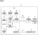
- FIG. 1 is a block diagram of a post-processing apparatus 10 including an electric stapler 20A in accordance with the present embodiment.
- the post-processing apparatus 10 is an example of the sheet processing apparatus, and is disposed on a downstream side of an image forming apparatus (not shown) configured to form an image on a sheet with respect to a sheet conveying direction, for example.
- the post-processing apparatus 10 includes a control unit 12 on the apparatus-side configured to control the apparatus as a whole, a communication interface 14 configured to perform communication with an electric stapler 20A that is another device, a power supply unit 16 configured to feed power to the electric stapler 20A and the like, and the electric stapler 20A configured to execute binding processing for a sheet bundle consisting of bundled sheets discharged from the image forming apparatus by using staples.
- the electric stapler 20A may also be attached to the image forming apparatus (for example, a sheet discharge opening).
- the control unit 12 on the apparatus-side is connected to the electric stapler 20A via the communication interface 14 and a communication line 40, and is configured to implement predetermined binding processing by transmitting and receiving signals (commands) for the binding processing to and from the electric stapler 20A. For example, an operation start signal and an operation stop signal of the electric stapler 20A are transmitted to the electric stapler 20A. Also, when there is a plurality of operations modes in which binding processing rates are different, a signal for executing a mode designated from an outside is transmitted to the electric stapler 20A. Also, the control unit 12 on the apparatus-side is connected to a control unit on the image forming apparatus-side, and is configured to control the electric stapler 20A and the like in conjunction with the image forming apparatus. In the meantime, the communication line 40 will be described in detail later.
- the power supply unit 16 is supplied with power from a commercial power supply or the image forming apparatus, and feeds the power to the electric stapler 20A and the like embedded in the post-processing apparatus 10.
- the electric stapler 20A includes a binding unit 70 (refer to FIG. 2 ) configured to execute the binding processing for the sheet bundle, a motor 28 configured to drive the binding unit 70, a control unit 22 configured to control the motor 28, and a communication interface 24 for performing communication with the control unit 12 on the apparatus-side. Also, the electric stapler 20A includes a drive circuit 26 configured to regulate a voltage that is supplied to the motor 28, a first sensor 34, a second sensor 36 and a third sensor 38 configured to detect various states of the electric stapler 20A, and a converter 32 configured to convert a drive-system voltage (24V) that is supplied from the post-processing apparatus 10 into a control-system voltage (5V).
- a drive-system voltage 24V
- the motor 28 is configured by a brushless motor including a rotor and a stator, and is configured to rotate at a predetermined speed on the basis of a voltage that is supplied from the drive circuit 26, thereby driving the binding unit 70.
- the motor 28 has a Hall sensor 30 embedded therein.
- the Hall sensor 30 is an example of the rotation number detection unit (load detection unit), and is configured to detect a magnet polarity of the rotor configuring the motor 28, thereby outputting position signals (the number of rotations of the motor 28) indicative of positions of the rotor to the control unit 22.
- the control unit 22 includes a CPU (Central Processing Unit) 23.
- the CPU 23 is configured to implement the predetermined binding processing by executing a variety of programs stored in a storage unit (not shown).
- the control unit 22 is configured to generate a drive signal for driving the drive circuit 26, based on the position signals from the Hall sensor 30 of the motor 28, a set command values and the like, and to output the generated drive signal to the drive circuit 26.
- the control unit 22 is configured to calculate a rotating speed of the motor 28, based on the positions signals from the Hall sensor 30 and the like, and to control the motor 28, based on the calculated rotating speed.
- the control unit 22 is configured to regulate a duty ratio of a PWM (Pulse Width Modulation) in the drive circuit 26 so as to follow a preset target rotating speed of the motor 28 based on the rotating speed of the motor 28.
- PWM Pulse Width Modulation
- the drive circuit 26 includes an inverter having a plurality of switching elements, and is configured to control the rotating speed of the motor 28 by the inverter.
- the switching element for example, a MOSFET (electric field transistor), an IGBT (insulated gate bipolar transistor) and the like can be used.
- the drive circuit 26 is configured to control on and off states of the switching elements, based on the drive signal supplied from the control unit 22, thereby regulating power that is fed to the motor 28. In the meantime, the drive circuit 26 may also be embedded in the motor 28.
- the communication interface 24 has a connector corresponding to standards for performing serial communication with the post-processing apparatus 10.
- the communication interface 24 is connected to a connector provided at one end portion of the communication line 40, and a connector provided at the other end portion of the communication line 40 is connected to the communication interface 14 of the post-processing apparatus 10.
- the communication line 40 includes a first wire 41 for transmitting a signal from the electric stapler 20A to the post-processing apparatus 10, and a second wire 42 for transmitting a signal from the post-processing apparatus 10 to the electric stapler 20A.
- the first wire 41 is configured to transmit state information of the electric stapler 20A, which is a detection result from the first sensor 34 and the like of the electric stapler 20A, to the post-processing apparatus 10, for example.
- the second wire 42 is configured to transmit the operation start signal and the operation stop signal of the electric stapler 20A to the electric stapler 20A, for example.
- the converter 32 is connected to the power supply unit 16 of the post-processing apparatus 10 via a power supply line 44.
- the power supply line 44 is configured by two positive and negative wires.
- the converter 32 is configured to convert a drive-system voltage that is supplied from the post-processing apparatus 10 into a control-system voltage, and to supply the converted control-system voltage to the drive circuit 26.
- the control-system voltage is, for example, 5V
- the first sensor 34 is an example of a stapler state detection unit, and is configured to detect whether a gear 73 (refer to FIG. 2 ) configured to drive the binding unit 70 and the like rotates by one revolution from an initial position (hereinbelow, referred to as a home position) and returns to the home position, and to output a result of the detection to the control unit 22.
- a gear 73 (refer to FIG. 2 ) configured to drive the binding unit 70 and the like rotates by one revolution from an initial position (hereinbelow, referred to as a home position) and returns to the home position, and to output a result of the detection to the control unit 22.
- the second sensor 36 is an example of a stapler state detection unit, and is configured to detect whether a staple bent by a forming plate of a driver mechanism 60 is in a striking-out position in which it can be struck to the sheet bundle, and to output a result of the detection to the control unit 22.
- the third sensor 38 is an example of a stapler state detection unit, and is configured to detect whether the number of coupled staples accommodated in a cartridge 90 (refer to FIG. 3 ) is equal to or smaller than a predetermined value, and to output a result of the detection to the control unit 22.
- the coupled staples indicate that straight staples before being bent are coupled in a sheet shape.
- the example of the electric stapler 20A in which the three sensors are used has been described.
- the present disclosure is not limited thereto.
- a sensor for detecting states and the like of the electric stapler 20A may also be used, in addition to the three sensors.
- other sensors may be used, instead of the three sensors.
- FIG. 2 is a perspective view of the electric stapler 20A in accordance with the embodiment, as seen from the front
- FIG. 3 is a perspective view of an inside of the electric stapler 20A in accordance with the embodiment, as seen from the rear
- FIG. 4A is a perspective view of the electric stapler 20A in accordance with the embodiment, as seen from the rear
- FIG. 4B is a perspective view depicting a state where a bottom wall 51 of the electric stapler 20A shown in FIG. 4A is detached
- FIG. 5 is a perspective view of a substrate 80A that is mounted on the electric stapler 20A in accordance with the embodiment.
- a side of the electric stapler 20A on which the driver mechanism 60 is disposed is referred to as a front side of the electric stapler 20A, and an opposite side thereof is referred to as a rear side of the electric stapler 20A.
- a side of the electric stapler 20A on which gears 72 and 73 are provided is a referred to as a left side of the electric stapler 20A, and an opposite side thereof is referred to as a right side of the electric stapler 20A.
- a bottom wall 51-side of the main body part 50 is referred to as a lower side of the electric stapler 20A, and an opposite side thereof is referred to as an upper side of the electric stapler 20A.
- the electric stapler 20A includes a main body part 50 having a box shape of which an upper side is opened and in which the control unit 22 and the motor 28 are accommodated, and a binding unit 70 configured to execute binding processing for a sheet bundle by using staples.
- the main body part 50 has a rectangular bottom wall 51, as seen from above, a first sidewall 52 erected from a left end of the bottom wall 51, a second sidewall 53 facing the first sidewall 52 and erected from a right end of the bottom wall 51, a front wall 54 erected from a front end of the bottom wall 51, and a rear wall 55 facing the front wall 54 and erected from a rear end of the bottom wall 51.
- the binding unit 70 includes a driver mechanism 60, a clincher arm 62, and a clincher part 64.
- a placement 66 on which a sheet bundle is to be placed is provided in a position above the driver mechanism 60 and facing the clincher part 64.
- the driver mechanism 60 is disposed in a front side of the main body part 50 and is configured to move up and down relative to the placement 66 as the motor 28 is driven.
- the driver mechanism 60 is configured to bend both ends of a staple into a substantial U-shape by a forming plate (not shown), and to strike out the staple formed into the U-shape toward the sheet bundle by a driver (not shown).
- the clincher arm 62 is provided to be rotatable toward an upper side of the driver mechanism 60, and is configured so that a front end side thereof can move toward and away from the driver mechanism 60.
- the clincher part 64 is provided at a front end portion of the clincher arm 62, and is configured to bind the sheet bundle with the staple by bending inwardly leg portions of the staple having penetrated the sheet bundle in cooperation with the driver mechanism 60.
- a cartridge 90 is detachably attached to the main body part 50.
- a refill in which sheet-shaped coupled staples are stacked is accommodated.
- the coupled staples in the refill of the cartridge 90 are conveyed to a forming position by a delivery mechanism (not shown) of the driver mechanism 60.
- the motor 28 is disposed in a rear side of the main body part 50 and below the cartridge 90.
- the gears 72 and 73 configured to rotate in conjunction with drive of the motor 28 are attached to an outer surface of the first sidewall 52.
- the gear 72 is connected to a rotary shaft of the motor 28, and the gear 73 is connected to the gear 72.
- a swing arm (not shown) is directly or indirectly connected between the gear 73 and the binding unit 70 such as the driver mechanism 60, the clincher part 64 and the like, so that the driver mechanism 60, the clincher part 64 and the like are driven in conjunction with rotation of the gear 73.
- the substrate 80A is disposed in a position (above the bottom wall 51) adjacent to the bottom wall 51 in the main body part 50. Specifically, the substrate 80A is disposed in a position in which the substrate does not overlap the motor 28, as seen from above, in a space between the driver mechanism 60 and the cartridge 90 and the bottom wall 51.
- a sensor group of the first sensor 34, the second sensor 36 and the third sensor 38, the control unit 22, the communication interface 24, and the drive circuit 26 are mounted on one surface of the substrate 80A. That is, the sensor group, the control unit 22, and the like are mounted on the same substrate 80A.
- the first sensor 34 is configured by a transmission type sensor having a light emitting unit and a light receiving unit, and is configured to output, to the control unit 22, a detection signal based on whether light is shielded by an actuator configured to operate in conjunction with a rotating operation of the gear 73.
- the second sensor 36 is configured by a transmission type sensor having a light emitting unit and a light receiving unit, and is configured to output, to the control unit 22, a detection signal based on whether light is shielded by an actuator configured to operate in conjunction with a staple moving to a striking-out position.
- the third sensor 38 is configured by a transmission type sensor having a light emitting unit and a light receiving unit, and is configured to output, to the control unit 22, a detection signal based on whether light is shielded by an actuator configured to operate in conjunction with the number of staples accommodated in the cartridge 90.
- the clincher part 64 is disposed in an uppermost position of a moving range (hereinbelow, referred to as a home position of the clincher part 64), and the driver of the driver mechanism 60 is disposed in a lowest position of the moving range (hereinbelow, referred to as a home position of the driver).
- a sheet on which an image is formed by the image forming apparatus is conveyed to the electric stapler 20A in the post-processing apparatus 10.
- a sheet bundle consisting of a plurality of sheets is placed on the placement 66 of the electric stapler 20A.
- the control unit 22 of the electric stapler 20A starts the drive of the motor 28, based on an operation start signal transmitted from the control unit 12 on the apparatus-side via the communication interface 14, the communication line 40 and the communication interface 24.
- the gears 72 and 73 rotate.
- the clincher arm 62 rotates, so that the clincher part 64 moves toward the placement 66 and the sheet bundle is clinched by the clincher part 64 and the placement 66 (clinch process).
- the forming plate of the driver mechanism 60 moves upward to bend a staple of the coupled staples located in the tip end position into a substantial U-shape.
- the driver of the driver mechanism 60 moves toward the placement 66 to push out the staple bent into a U-shape toward the sheet bundle, thereby causing the leg portions of the staple to penetrate the sheet bundle in a thickness direction (penetration process).
- penetration process a crown portion of the staple is brought into contact with the lowest surface of the sheet bundle.
- the control unit 22 of the electric stapler 20A transmits state information, which indicates that the gear 73 has returned to the home position, to the control unit 12 on the apparatus-side via the communication interface 24 and the like.
- the control unit 12 on the apparatus-side transmits an operation stop signal for stopping the binding processing of the electric stapler 20A based on the state information of the electric stapler 20A to the control unit 22 of the electric stapler 20A via the communication interface 14 and the like.
- the control unit 22 of the electric stapler 20A stops the drive of the motor 28, based on the operation stop signal transmitted from the post-processing apparatus 10.
- the electric stapler 20A-side is provided with the drive circuit 26 configured to drive the motor 28, the control unit 22 configured to control the drive circuit 26, and the communication interface 24 configured to perform communication with the post-processing apparatus 10.
- the electric stapler 20A and the post-processing apparatus 10 can be connected to each other only by the two-system harness of the communication line 40 for transmitting the operation start signal, the operation stop signal and the like of the binding processing from the post-processing apparatus 10 to the electric stapler 20A and transmitting the state information of the electric stapler 20A to the post-processing apparatus 10, and the power supply line 44 for feeding the power from the post-processing apparatus 10 to the electric stapler 20A.
- the electric stapler-side is not provided with the control unit, the drive circuit and the like, it is necessary to provide a three-system harness of a harness for transmitting the state information of the electric stapler from the electric stapler to the post-processing apparatus, a harness for transmitting a drive signal for controlling a motor from the post-processing apparatus to the electric stapler, and a harness for feeding power from the post-processing apparatus to the electric stapler.
- the present embodiment it is possible to reduce the harnesses from the three systems to the two systems and to reduce the number of wires for interconnecting the electric stapler 20A and the post-processing apparatus 10, as compared to the electric stapler of the related art. Thereby, it is possible to reduce the cost, to simplify arrangement of the wires, to reduce the noise and to improve the durability. Also, even when the number of various sensors increases as the electric stapler 20A is highly functionalized, it is possible to prevent an increase in the number of wires.
- control unit 22, the communication interface 24, the drive circuit 26, and the sensor group of the first sensor 34, the second sensor 36 and the third sensor 38 are mounted on the same substrate 80A, and the substrate 80Ais disposed in the position adjacent to the bottom wall 51 of the main body part 50 of the electric stapler 20A. That is, it is possible to dispose the substrate 80A in the empty space in the main body part 50 while avoiding the motor and the mechanism part such as a cam disposed in the main body part 50. Thereby, it is possible to save the space, so that it is possible to make the electric stapler 20A smaller.
- the brushless motor in which the drive circuit 26 and the Hall sensor 30 are embedded is used as the motor 28, so that it is not necessary to separately provide an encoder for detecting the number of rotations, and the like. Therefore, it is possible to make the electric stapler 20A further smaller. Also, the brushless motor is used, so that it is possible to calculate the rotating speed of the motor 28, and to control the rotating speed of the motor 28, based on the calculated rotating speed.
- FIG. 4B of the embodiment depicts the example where the substrate 80A is disposed in the position adjacent to the bottom wall 51 of the main body part 50 of the electric stapler 20A.
- the present disclosure is not limited thereto.
- FIG. 6 is a perspective view of an electric stapler 20B in accordance with a first modified embodiment, as seen from the front.
- a configuration of the electric stapler 20B is similar to the electric stapler 20A, except that an attaching position of a substrate 80B to the main body part 50 is different, the common constitutional elements are denoted with the same reference signs and the detailed descriptions thereof are omitted.
- the substrate 80B is disposed in a position adjacent to the second sidewall 53 of the main body part 50. That is, in the first modified embodiment, the substrate 80B is attached on an outer surface of the second sidewall 53, not the first sidewall 52 to which the gears 72 and 73 are attached.
- the substrate 80B since the substrate 80B is attached on the outer surface of the second sidewall 53, it is possible to make the electric stapler 20B smaller without influencing a layout of the driver mechanism 60 and the like in the main body part 50.
- the substrate 80B may also be attached on an inner surface of the second sidewall 53, not the outer surface of the second sidewall 53.
- the Hall sensor 30 is embedded in the motor 28, and the position and number of rotations of the rotor that are examples of the load of the motor 28 are detected by the Hall sensor 30.
- the present disclosure is not limited thereto.
- a current detection unit may be provided instead of the Hall sensor 30, and a current value applied to the motor 28 as the load of the motor 28 may be detected.
- the communication interfaces 14 and 24 are interconnected by the wired communication line 40.
- the present disclosure is not limited thereto.
- the communication interfaces 14 and 24 may be provided with a wireless communication function, respectively, and may be interconnected in a wireless manner.
Landscapes
- Engineering & Computer Science (AREA)
- Textile Engineering (AREA)
- Mechanical Engineering (AREA)
- Life Sciences & Earth Sciences (AREA)
- Forests & Forestry (AREA)
- Power Engineering (AREA)
- Physics & Mathematics (AREA)
- General Physics & Mathematics (AREA)
- Automation & Control Theory (AREA)
- Portable Nailing Machines And Staplers (AREA)
- Dovetailed Work, And Nailing Machines And Stapling Machines For Wood (AREA)
Abstract
Description
- The present disclosure relates to an electric stapler.
- In the related art, a post-processing apparatus in which an electric stapler is embedded is widely used (for example, Patent Literature 1). The post-processing apparatus includes a control unit for controlling the electric stapler. The control unit is configured to transmit an operation start command, an operation stop command and the like to the electric stapler, based on a state of a sheet bundle, a state of staples in a staple accommodation unit and the like transmitted from the electric stapler. The electric stapler can execute binding processing, based on the commands transmitted from the control unit.
- Patent Literature 1:
JP-A-2004-002021 - The control unit is disposed outside the electric stapler, and is connected to the electric stapler by a plurality of wires. When executing the binding processing in the electric stapler, it is necessary for the electric stapler to transmit, to the control unit, signals indicative of various states of the electric stapler-side. For this reason, many wires are required so as to interconnect the control unit and the electric stapler. Also, in recent years, the electric stapler is highly functionalized. However, when the electric stapler is highly functionalized, the number of drive sources such as a motor, a variety of sensors and the like also increases. Therefore, the number of signals from the electric stapler to the control unit further increases, and the wires interconnecting the electric stapler and the post-processing apparatus become larger. As a result, problems such as an increase in cost due to the increase in the number of wires, arrangement of wires, noise and the like become more prominent.
- It is therefore an object of the present disclosure to provide an electric stapler capable of reducing the number of wires extending outward from an electric stapler as small as possible.
- According to the disclosure, there is provided an electric stapler configured to perform communication with a sheet processing apparatus, the electric stapler comprising: a binding unit configured to execute binding processing for a sheet bundle; a motor configured to drive the binding unit; a control unit configured to control the motor; and a communication interface configured to perform communication with the sheet processing apparatus, wherein the control unit controls the motor to execute the binding processing by the binding unit when a predetermined signal is received from the sheet processing apparatus via the communication interface.
- In the meantime, the electric stapler may be embedded in an image forming apparatus (a complex machine, a copier and the like), in addition to the post-processing apparatus, in some cases. As used herein, the "sheet processing apparatus" has a meaning including both the post-processing apparatus and the image forming apparatus.
- According to an aspect of the present disclosure, the electric stapler, the control unit that is conventionally provided in the post-processing apparatus (sheet processing apparatus) is provided in the electric stapler. Therefore, only the communication line for transmitting and receiving the operation start command, the operation stop command and the like between the electric stapler and the post-processing apparatus is required, so that it is possible to reduce the number of wires for interconnecting the electric stapler and the sheet processing apparatus.
-
-
FIG. 1 is a block diagram of a post-processing apparatus including an electric stapler in accordance with an embodiment. -
FIG. 2 is a perspective view of the electric stapler in accordance with the embodiment, as seen from the front. -
FIG. 3 is a perspective view of an inside of the electric stapler in accordance with the embodiment, as seen from the rear. -
FIG. 4A is a perspective view of the electric stapler in accordance with the embodiment, as seen from the rear. -
FIG. 4B is a perspective view depicting a state where a bottom wall of the electric stapler shown inFIG. 4A is detached. -
FIG. 5 is a perspective view of a substrate that is mounted on the electric stapler in accordance with the embodiment. -
FIG. 6 is a perspective view of an electric stapler in accordance with a first modified embodiment, as seen from the front. -
FIG. 1 is a block diagram of apost-processing apparatus 10 including anelectric stapler 20A in accordance with the present embodiment. - The
post-processing apparatus 10 is an example of the sheet processing apparatus, and is disposed on a downstream side of an image forming apparatus (not shown) configured to form an image on a sheet with respect to a sheet conveying direction, for example. Thepost-processing apparatus 10 includes acontrol unit 12 on the apparatus-side configured to control the apparatus as a whole, acommunication interface 14 configured to perform communication with anelectric stapler 20A that is another device, apower supply unit 16 configured to feed power to theelectric stapler 20A and the like, and theelectric stapler 20A configured to execute binding processing for a sheet bundle consisting of bundled sheets discharged from the image forming apparatus by using staples. In the meantime, in addition to the configuration where theelectric stapler 20A is embedded in thepost-processing apparatus 10, like the present embodiment, theelectric stapler 20A may also be attached to the image forming apparatus (for example, a sheet discharge opening). - The
control unit 12 on the apparatus-side is connected to theelectric stapler 20A via thecommunication interface 14 and acommunication line 40, and is configured to implement predetermined binding processing by transmitting and receiving signals (commands) for the binding processing to and from theelectric stapler 20A. For example, an operation start signal and an operation stop signal of theelectric stapler 20A are transmitted to theelectric stapler 20A. Also, when there is a plurality of operations modes in which binding processing rates are different, a signal for executing a mode designated from an outside is transmitted to theelectric stapler 20A. Also, thecontrol unit 12 on the apparatus-side is connected to a control unit on the image forming apparatus-side, and is configured to control theelectric stapler 20A and the like in conjunction with the image forming apparatus. In the meantime, thecommunication line 40 will be described in detail later. - The
power supply unit 16 is supplied with power from a commercial power supply or the image forming apparatus, and feeds the power to theelectric stapler 20A and the like embedded in thepost-processing apparatus 10. - The
electric stapler 20A includes a binding unit 70 (refer toFIG. 2 ) configured to execute the binding processing for the sheet bundle, amotor 28 configured to drive thebinding unit 70, acontrol unit 22 configured to control themotor 28, and acommunication interface 24 for performing communication with thecontrol unit 12 on the apparatus-side. Also, theelectric stapler 20A includes adrive circuit 26 configured to regulate a voltage that is supplied to themotor 28, afirst sensor 34, asecond sensor 36 and athird sensor 38 configured to detect various states of theelectric stapler 20A, and aconverter 32 configured to convert a drive-system voltage (24V) that is supplied from thepost-processing apparatus 10 into a control-system voltage (5V). - The
motor 28 is configured by a brushless motor including a rotor and a stator, and is configured to rotate at a predetermined speed on the basis of a voltage that is supplied from thedrive circuit 26, thereby driving thebinding unit 70. Themotor 28 has aHall sensor 30 embedded therein. TheHall sensor 30 is an example of the rotation number detection unit (load detection unit), and is configured to detect a magnet polarity of the rotor configuring themotor 28, thereby outputting position signals (the number of rotations of the motor 28) indicative of positions of the rotor to thecontrol unit 22. - The
control unit 22 includes a CPU (Central Processing Unit) 23. The CPU 23 is configured to implement the predetermined binding processing by executing a variety of programs stored in a storage unit (not shown). Also, thecontrol unit 22 is configured to generate a drive signal for driving thedrive circuit 26, based on the position signals from theHall sensor 30 of themotor 28, a set command values and the like, and to output the generated drive signal to thedrive circuit 26. Specifically, thecontrol unit 22 is configured to calculate a rotating speed of themotor 28, based on the positions signals from theHall sensor 30 and the like, and to control themotor 28, based on the calculated rotating speed. Specifically, thecontrol unit 22 is configured to regulate a duty ratio of a PWM (Pulse Width Modulation) in thedrive circuit 26 so as to follow a preset target rotating speed of themotor 28 based on the rotating speed of themotor 28. - The
drive circuit 26 includes an inverter having a plurality of switching elements, and is configured to control the rotating speed of themotor 28 by the inverter. As the switching element, for example, a MOSFET (electric field transistor), an IGBT (insulated gate bipolar transistor) and the like can be used. Thedrive circuit 26 is configured to control on and off states of the switching elements, based on the drive signal supplied from thecontrol unit 22, thereby regulating power that is fed to themotor 28. In the meantime, thedrive circuit 26 may also be embedded in themotor 28. - The
communication interface 24 has a connector corresponding to standards for performing serial communication with thepost-processing apparatus 10. Thecommunication interface 24 is connected to a connector provided at one end portion of thecommunication line 40, and a connector provided at the other end portion of thecommunication line 40 is connected to thecommunication interface 14 of thepost-processing apparatus 10. - The
communication line 40 includes afirst wire 41 for transmitting a signal from theelectric stapler 20A to thepost-processing apparatus 10, and asecond wire 42 for transmitting a signal from thepost-processing apparatus 10 to theelectric stapler 20A. Thefirst wire 41 is configured to transmit state information of theelectric stapler 20A, which is a detection result from thefirst sensor 34 and the like of theelectric stapler 20A, to thepost-processing apparatus 10, for example. Thesecond wire 42 is configured to transmit the operation start signal and the operation stop signal of theelectric stapler 20A to theelectric stapler 20A, for example. - The
converter 32 is connected to thepower supply unit 16 of thepost-processing apparatus 10 via apower supply line 44. Thepower supply line 44 is configured by two positive and negative wires. Theconverter 32 is configured to convert a drive-system voltage that is supplied from thepost-processing apparatus 10 into a control-system voltage, and to supply the converted control-system voltage to thedrive circuit 26. The control-system voltage is, for example, 5V - The
first sensor 34 is an example of a stapler state detection unit, and is configured to detect whether a gear 73 (refer toFIG. 2 ) configured to drive the bindingunit 70 and the like rotates by one revolution from an initial position (hereinbelow, referred to as a home position) and returns to the home position, and to output a result of the detection to thecontrol unit 22. - The
second sensor 36 is an example of a stapler state detection unit, and is configured to detect whether a staple bent by a forming plate of adriver mechanism 60 is in a striking-out position in which it can be struck to the sheet bundle, and to output a result of the detection to thecontrol unit 22. - The
third sensor 38 is an example of a stapler state detection unit, and is configured to detect whether the number of coupled staples accommodated in a cartridge 90 (refer toFIG. 3 ) is equal to or smaller than a predetermined value, and to output a result of the detection to thecontrol unit 22. As used herein, the coupled staples indicate that straight staples before being bent are coupled in a sheet shape. - In the meantime, in the present embodiment, the example of the
electric stapler 20A in which the three sensors are used has been described. However, the present disclosure is not limited thereto. For example, a sensor for detecting states and the like of theelectric stapler 20A may also be used, in addition to the three sensors. Also, other sensors may be used, instead of the three sensors. -
FIG. 2 is a perspective view of theelectric stapler 20A in accordance with the embodiment, as seen from the front,FIG. 3 is a perspective view of an inside of theelectric stapler 20A in accordance with the embodiment, as seen from the rear,FIG. 4A is a perspective view of theelectric stapler 20A in accordance with the embodiment, as seen from the rear,FIG. 4B is a perspective view depicting a state where abottom wall 51 of theelectric stapler 20A shown inFIG. 4A is detached, andFIG. 5 is a perspective view of asubstrate 80A that is mounted on theelectric stapler 20A in accordance with the embodiment. - In the meantime, in
FIGS. 2 to 5 , a side of theelectric stapler 20A on which thedriver mechanism 60 is disposed is referred to as a front side of theelectric stapler 20A, and an opposite side thereof is referred to as a rear side of theelectric stapler 20A. Also, a side of theelectric stapler 20A on which gears 72 and 73 are provided is a referred to as a left side of theelectric stapler 20A, and an opposite side thereof is referred to as a right side of theelectric stapler 20A. Also, a bottom wall 51-side of themain body part 50 is referred to as a lower side of theelectric stapler 20A, and an opposite side thereof is referred to as an upper side of theelectric stapler 20A. - The
electric stapler 20A includes amain body part 50 having a box shape of which an upper side is opened and in which thecontrol unit 22 and themotor 28 are accommodated, and a bindingunit 70 configured to execute binding processing for a sheet bundle by using staples. - The
main body part 50 has arectangular bottom wall 51, as seen from above, afirst sidewall 52 erected from a left end of thebottom wall 51, asecond sidewall 53 facing thefirst sidewall 52 and erected from a right end of thebottom wall 51, afront wall 54 erected from a front end of thebottom wall 51, and arear wall 55 facing thefront wall 54 and erected from a rear end of thebottom wall 51. - The binding
unit 70 includes adriver mechanism 60, aclincher arm 62, and aclincher part 64. Aplacement 66 on which a sheet bundle is to be placed is provided in a position above thedriver mechanism 60 and facing theclincher part 64. - The
driver mechanism 60 is disposed in a front side of themain body part 50 and is configured to move up and down relative to theplacement 66 as themotor 28 is driven. Thedriver mechanism 60 is configured to bend both ends of a staple into a substantial U-shape by a forming plate (not shown), and to strike out the staple formed into the U-shape toward the sheet bundle by a driver (not shown). - The
clincher arm 62 is provided to be rotatable toward an upper side of thedriver mechanism 60, and is configured so that a front end side thereof can move toward and away from thedriver mechanism 60. Theclincher part 64 is provided at a front end portion of theclincher arm 62, and is configured to bind the sheet bundle with the staple by bending inwardly leg portions of the staple having penetrated the sheet bundle in cooperation with thedriver mechanism 60. - A
cartridge 90 is detachably attached to themain body part 50. In thecartridge 90, a refill in which sheet-shaped coupled staples are stacked is accommodated. The coupled staples in the refill of thecartridge 90 are conveyed to a forming position by a delivery mechanism (not shown) of thedriver mechanism 60. - The
motor 28 is disposed in a rear side of themain body part 50 and below thecartridge 90. Thegears motor 28 are attached to an outer surface of thefirst sidewall 52. Thegear 72 is connected to a rotary shaft of themotor 28, and thegear 73 is connected to thegear 72. A swing arm (not shown) is directly or indirectly connected between thegear 73 and the bindingunit 70 such as thedriver mechanism 60, theclincher part 64 and the like, so that thedriver mechanism 60, theclincher part 64 and the like are driven in conjunction with rotation of thegear 73. In the present embodiment, while thegear 73 and the like rotate by one revolution, a clamp process of moving theclincher part 64 down to clamp the sheet bundle, a penetration process of causing the leg portions of the staple to penetrate the sheet bundle by upward movement of thedriver mechanism 60, and a clinch process of bending the staple by theclincher part 64, and a return process of returning theclincher part 64, thedriver mechanism 60 and the like to the home position are executed. - Also, in the present embodiment, as shown in
FIG. 4B , thesubstrate 80A is disposed in a position (above the bottom wall 51) adjacent to thebottom wall 51 in themain body part 50. Specifically, thesubstrate 80A is disposed in a position in which the substrate does not overlap themotor 28, as seen from above, in a space between thedriver mechanism 60 and thecartridge 90 and thebottom wall 51. On one surface of thesubstrate 80A, a sensor group of thefirst sensor 34, thesecond sensor 36 and thethird sensor 38, thecontrol unit 22, thecommunication interface 24, and thedrive circuit 26 are mounted. That is, the sensor group, thecontrol unit 22, and the like are mounted on thesame substrate 80A. - The
first sensor 34 is configured by a transmission type sensor having a light emitting unit and a light receiving unit, and is configured to output, to thecontrol unit 22, a detection signal based on whether light is shielded by an actuator configured to operate in conjunction with a rotating operation of thegear 73. - The
second sensor 36 is configured by a transmission type sensor having a light emitting unit and a light receiving unit, and is configured to output, to thecontrol unit 22, a detection signal based on whether light is shielded by an actuator configured to operate in conjunction with a staple moving to a striking-out position. - The
third sensor 38 is configured by a transmission type sensor having a light emitting unit and a light receiving unit, and is configured to output, to thecontrol unit 22, a detection signal based on whether light is shielded by an actuator configured to operate in conjunction with the number of staples accommodated in thecartridge 90. - Subsequently, an example of the operation of the
electric stapler 20A is described with reference toFIGS. 1 to 5 . - Before the drive of the
motor 28 starts and immediately after the drive of themotor 28 starts, theclincher part 64 is disposed in an uppermost position of a moving range (hereinbelow, referred to as a home position of the clincher part 64), and the driver of thedriver mechanism 60 is disposed in a lowest position of the moving range (hereinbelow, referred to as a home position of the driver). - A sheet on which an image is formed by the image forming apparatus is conveyed to the
electric stapler 20A in thepost-processing apparatus 10. A sheet bundle consisting of a plurality of sheets is placed on theplacement 66 of theelectric stapler 20A. - The
control unit 22 of theelectric stapler 20A starts the drive of themotor 28, based on an operation start signal transmitted from thecontrol unit 12 on the apparatus-side via thecommunication interface 14, thecommunication line 40 and thecommunication interface 24. In association with the drive, thegears gear 73 and the like rotate, theclincher arm 62 rotates, so that theclincher part 64 moves toward theplacement 66 and the sheet bundle is clinched by theclincher part 64 and the placement 66 (clinch process). - Also, when the
gear 73 rotates by a predetermined angle, the forming plate of thedriver mechanism 60 moves upward to bend a staple of the coupled staples located in the tip end position into a substantial U-shape. At the same time, the driver of thedriver mechanism 60 moves toward theplacement 66 to push out the staple bent into a U-shape toward the sheet bundle, thereby causing the leg portions of the staple to penetrate the sheet bundle in a thickness direction (penetration process). At this time, a crown portion of the staple is brought into contact with the lowest surface of the sheet bundle. - Continuously, when the
gear 73 rotates by a predetermined angle, theclincher part 64 is driven and the leg portions of the staple protruding from the top surface of the sheet bundle are bent inwardly by theclincher part 64, so that the sheet bundle is bound with the staple (clinch process). - Also, when the
gear 73 rotates to a position close to the home position about by one revolution, theclincher arm 62 rotates, theclincher part 64 moves upward to return to the home position, and the driver of thedriver mechanism 60 moves downward to return to the home position (return process). In this way, while thegear 73 rotates by one revolution, a series of binding processing including the clamp process, the penetration process, the clinch process and the return process is executed. - In this case, the
control unit 22 of theelectric stapler 20A transmits state information, which indicates that thegear 73 has returned to the home position, to thecontrol unit 12 on the apparatus-side via thecommunication interface 24 and the like. Thecontrol unit 12 on the apparatus-side transmits an operation stop signal for stopping the binding processing of theelectric stapler 20A based on the state information of theelectric stapler 20A to thecontrol unit 22 of theelectric stapler 20A via thecommunication interface 14 and the like. Thecontrol unit 22 of theelectric stapler 20A stops the drive of themotor 28, based on the operation stop signal transmitted from thepost-processing apparatus 10. - As described above, in the present embodiment, the
electric stapler 20A-side is provided with thedrive circuit 26 configured to drive themotor 28, thecontrol unit 22 configured to control thedrive circuit 26, and thecommunication interface 24 configured to perform communication with thepost-processing apparatus 10. For this reason, theelectric stapler 20A and thepost-processing apparatus 10 can be connected to each other only by the two-system harness of thecommunication line 40 for transmitting the operation start signal, the operation stop signal and the like of the binding processing from thepost-processing apparatus 10 to theelectric stapler 20A and transmitting the state information of theelectric stapler 20A to thepost-processing apparatus 10, and thepower supply line 44 for feeding the power from thepost-processing apparatus 10 to theelectric stapler 20A. - In contrast, according to the electric stapler of the related art, since the electric stapler-side is not provided with the control unit, the drive circuit and the like, it is necessary to provide a three-system harness of a harness for transmitting the state information of the electric stapler from the electric stapler to the post-processing apparatus, a harness for transmitting a drive signal for controlling a motor from the post-processing apparatus to the electric stapler, and a harness for feeding power from the post-processing apparatus to the electric stapler.
- However, according to the present embodiment, it is possible to reduce the harnesses from the three systems to the two systems and to reduce the number of wires for interconnecting the
electric stapler 20A and thepost-processing apparatus 10, as compared to the electric stapler of the related art. Thereby, it is possible to reduce the cost, to simplify arrangement of the wires, to reduce the noise and to improve the durability. Also, even when the number of various sensors increases as theelectric stapler 20A is highly functionalized, it is possible to prevent an increase in the number of wires. - Also, in the present embodiment, the
control unit 22, thecommunication interface 24, thedrive circuit 26, and the sensor group of thefirst sensor 34, thesecond sensor 36 and thethird sensor 38 are mounted on thesame substrate 80A, and the substrate 80Ais disposed in the position adjacent to thebottom wall 51 of themain body part 50 of theelectric stapler 20A. That is, it is possible to dispose thesubstrate 80A in the empty space in themain body part 50 while avoiding the motor and the mechanism part such as a cam disposed in themain body part 50. Thereby, it is possible to save the space, so that it is possible to make theelectric stapler 20A smaller. Also, the brushless motor in which thedrive circuit 26 and theHall sensor 30 are embedded is used as themotor 28, so that it is not necessary to separately provide an encoder for detecting the number of rotations, and the like. Therefore, it is possible to make theelectric stapler 20A further smaller. Also, the brushless motor is used, so that it is possible to calculate the rotating speed of themotor 28, and to control the rotating speed of themotor 28, based on the calculated rotating speed. - In the meantime,
FIG. 4B of the embodiment depicts the example where thesubstrate 80A is disposed in the position adjacent to thebottom wall 51 of themain body part 50 of theelectric stapler 20A. However, the present disclosure is not limited thereto. -
FIG. 6 is a perspective view of anelectric stapler 20B in accordance with a first modified embodiment, as seen from the front. In the meantime, since a configuration of theelectric stapler 20B is similar to theelectric stapler 20A, except that an attaching position of asubstrate 80B to themain body part 50 is different, the common constitutional elements are denoted with the same reference signs and the detailed descriptions thereof are omitted. - In the
electric stapler 20B, thesubstrate 80B is disposed in a position adjacent to thesecond sidewall 53 of themain body part 50. That is, in the first modified embodiment, thesubstrate 80B is attached on an outer surface of thesecond sidewall 53, not thefirst sidewall 52 to which thegears - According to the first modified embodiment, since the
substrate 80B is attached on the outer surface of thesecond sidewall 53, it is possible to make theelectric stapler 20B smaller without influencing a layout of thedriver mechanism 60 and the like in themain body part 50. In the meantime, thesubstrate 80B may also be attached on an inner surface of thesecond sidewall 53, not the outer surface of thesecond sidewall 53. - In the meantime, in the embodiment and the first modified embodiment, although the embodiments of the present disclosure have been described in detail with reference to the drawings, the embodiments are provided just to illustrate the present disclosure, not to limit the present disclosure. Also, the embodiments can be variously modified and changed without departing from the essence and scope of the present disclosure.
- For example, in the embodiments, the
Hall sensor 30 is embedded in themotor 28, and the position and number of rotations of the rotor that are examples of the load of themotor 28 are detected by theHall sensor 30. However, the present disclosure is not limited thereto. For example, a current detection unit may be provided instead of theHall sensor 30, and a current value applied to themotor 28 as the load of themotor 28 may be detected. - Also, in the embodiments, the communication interfaces 14 and 24 are interconnected by the wired
communication line 40. However, the present disclosure is not limited thereto. For example, the communication interfaces 14 and 24 may be provided with a wireless communication function, respectively, and may be interconnected in a wireless manner.
Claims (8)
- An electric stapler configured to perform communication with a sheet processing apparatus, the electric stapler comprising:a binding unit configured to execute binding processing for a sheet bundle;a motor configured to drive the binding unit;a control unit configured to control the motor;a communication interface configured to perform communication with the sheet processing apparatus; anda main body part in which the motor and the control unit are accommodated,wherein the control unit controls the motor to execute the binding processing by the binding unit when a predetermined signal is received from the sheet processing apparatus via the communication interface.
- The electric stapler according to Claim 1, further comprising a load detection unit configured to detect a load of the motor,
wherein the control unit is configured to control the motor, based on the load of the motor detected by the load detection unit. - The electric stapler according to Claim 2, wherein the control unit is configured to control the motor so as to follow a preset target value, based on the load of the motor detected by the load detection unit.
- The electric stapler according to Claim 2 or 3, wherein the load detection unit includes a rotation number detection unit configured to detect a number of rotations of the motor or a current detection unit configured to detect a current value applied to the motor.
- The electric stapler according to any one of Claims 1 to 4, wherein the control unit is disposed below the binding unit and the motor.
- The electric stapler according to any one of Claims 1 to 5, wherein the main body part has a bottom wall, and
wherein the control unit is disposed in a position adjacent to the bottom wall. - The electric stapler according to any one of Claims 1 to 4, wherein the main body part has a sidewall, and
wherein the control unit is disposed in a position adjacent to the sidewall. - The electric stapler according to any one of Claims 1 to 7, further comprising a stapler state detection unit configured to detect whether or not a staple for binding the sheet bundle is present,
wherein the control unit is disposed on a same substrate as the stapler state detection unit.
Applications Claiming Priority (1)
| Application Number | Priority Date | Filing Date | Title |
|---|---|---|---|
| JP2019163937A JP2021041570A (en) | 2019-09-09 | 2019-09-09 | Electric stapler |
Publications (1)
| Publication Number | Publication Date |
|---|---|
| EP3790184A1 true EP3790184A1 (en) | 2021-03-10 |
Family
ID=72432820
Family Applications (1)
| Application Number | Title | Priority Date | Filing Date |
|---|---|---|---|
| EP20195229.8A Withdrawn EP3790184A1 (en) | 2019-09-09 | 2020-09-09 | Electric stapler |
Country Status (4)
| Country | Link |
|---|---|
| US (1) | US20210069928A1 (en) |
| EP (1) | EP3790184A1 (en) |
| JP (1) | JP2021041570A (en) |
| CN (1) | CN112455115A (en) |
Citations (6)
| Publication number | Priority date | Publication date | Assignee | Title |
|---|---|---|---|---|
| JPH08127466A (en) * | 1994-10-31 | 1996-05-21 | Canon Inc | Sheet binding device and image forming apparatus including the same |
| JPH08187681A (en) * | 1994-12-28 | 1996-07-23 | Nisca Corp | Electrically driven stapler and driving method thereof |
| JP2004002021A (en) | 2003-05-12 | 2004-01-08 | Fuji Xerox Co Ltd | Device for distributing and housing sheet |
| US20050140077A1 (en) * | 2003-12-26 | 2005-06-30 | Canon Kabushiki Kaisha | Post-processing device and post-processing method |
| JP2011111238A (en) * | 2009-11-24 | 2011-06-09 | Canon Inc | Sheet processing device and image forming apparatus |
| JP2011201166A (en) * | 2010-03-25 | 2011-10-13 | Fuji Xerox Co Ltd | Stapler driver, stapler driving method, stapler control program, post-treatment apparatus, and image forming device |
Family Cites Families (7)
| Publication number | Priority date | Publication date | Assignee | Title |
|---|---|---|---|---|
| US5791543A (en) * | 1995-12-11 | 1998-08-11 | Max Co., Ltd. | Electric stapler |
| JP3955251B2 (en) * | 2002-09-30 | 2007-08-08 | 松下電器産業株式会社 | Stapler |
| JP4029830B2 (en) * | 2003-12-04 | 2008-01-09 | マックス株式会社 | Detaching device for cartridge in electric stapler |
| JP2007022752A (en) * | 2005-07-15 | 2007-02-01 | Canon Inc | Staple device |
| CN101314445B (en) * | 2008-06-18 | 2011-02-02 | 株式会社东芝 | Post-treatment apparatus for paper, image forming apparatus and post-treatment method for paper |
| JP6136371B2 (en) * | 2013-03-04 | 2017-05-31 | 株式会社リコー | Paper post-processing device |
| JP5668886B1 (en) * | 2014-07-09 | 2015-02-12 | 富士ゼロックス株式会社 | Binding processing apparatus and image forming apparatus |
-
2019
- 2019-09-09 JP JP2019163937A patent/JP2021041570A/en active Pending
-
2020
- 2020-09-08 CN CN202010934888.1A patent/CN112455115A/en active Pending
- 2020-09-09 EP EP20195229.8A patent/EP3790184A1/en not_active Withdrawn
- 2020-09-09 US US17/015,994 patent/US20210069928A1/en not_active Abandoned
Patent Citations (6)
| Publication number | Priority date | Publication date | Assignee | Title |
|---|---|---|---|---|
| JPH08127466A (en) * | 1994-10-31 | 1996-05-21 | Canon Inc | Sheet binding device and image forming apparatus including the same |
| JPH08187681A (en) * | 1994-12-28 | 1996-07-23 | Nisca Corp | Electrically driven stapler and driving method thereof |
| JP2004002021A (en) | 2003-05-12 | 2004-01-08 | Fuji Xerox Co Ltd | Device for distributing and housing sheet |
| US20050140077A1 (en) * | 2003-12-26 | 2005-06-30 | Canon Kabushiki Kaisha | Post-processing device and post-processing method |
| JP2011111238A (en) * | 2009-11-24 | 2011-06-09 | Canon Inc | Sheet processing device and image forming apparatus |
| JP2011201166A (en) * | 2010-03-25 | 2011-10-13 | Fuji Xerox Co Ltd | Stapler driver, stapler driving method, stapler control program, post-treatment apparatus, and image forming device |
Also Published As
| Publication number | Publication date |
|---|---|
| US20210069928A1 (en) | 2021-03-11 |
| JP2021041570A (en) | 2021-03-18 |
| CN112455115A (en) | 2021-03-09 |
Similar Documents
| Publication | Publication Date | Title |
|---|---|---|
| EP2251147B1 (en) | Electric stapler and operation method of an electric stapler | |
| US7819143B2 (en) | Reinforcing bar binder, wire reel and method for identifying wire reel | |
| EP2679347B1 (en) | Cordless fastening tool control system | |
| US20030066858A1 (en) | Control device for a drive motor in a stapler | |
| US20100156020A1 (en) | Sheet post-processing apparatus | |
| US6948224B2 (en) | Automatic stapling method and stapler | |
| US20210069928A1 (en) | Electric stapler | |
| EP3789167B1 (en) | Electric stapler | |
| JP2013095555A (en) | Post-processing device and control method of the same | |
| EP1764658A2 (en) | Image forming apparatus including sheet processing unit capable of effectively aligning sheet | |
| EP2255935B1 (en) | Electric stapler | |
| WO2008023621A1 (en) | Sheet perforation device and its control method | |
| US12036809B2 (en) | Electric stapler and sheet processing apparatus | |
| EP1582322B1 (en) | Motorized stapler | |
| US6899325B2 (en) | Method and device for precisely aligning a product to be stapled in relation to a stapling device and gatherer stapler | |
| US20130140205A1 (en) | Staple cartridge | |
| JP2021041683A (en) | Electric stapler | |
| EP2172309A1 (en) | Stapling apparatus | |
| CN120901892A (en) | Fastener driver and fastener driving system | |
| JPH01146672A (en) | Sheet binder | |
| JP2004114354A (en) | Sensor device of motor-driven stapler |
Legal Events
| Date | Code | Title | Description |
|---|---|---|---|
| PUAI | Public reference made under article 153(3) epc to a published international application that has entered the european phase |
Free format text: ORIGINAL CODE: 0009012 |
|
| STAA | Information on the status of an ep patent application or granted ep patent |
Free format text: STATUS: THE APPLICATION HAS BEEN PUBLISHED |
|
| AK | Designated contracting states |
Kind code of ref document: A1 Designated state(s): AL AT BE BG CH CY CZ DE DK EE ES FI FR GB GR HR HU IE IS IT LI LT LU LV MC MK MT NL NO PL PT RO RS SE SI SK SM TR |
|
| AX | Request for extension of the european patent |
Extension state: BA ME |
|
| STAA | Information on the status of an ep patent application or granted ep patent |
Free format text: STATUS: REQUEST FOR EXAMINATION WAS MADE |
|
| 17P | Request for examination filed |
Effective date: 20210910 |
|
| RBV | Designated contracting states (corrected) |
Designated state(s): AL AT BE BG CH CY CZ DE DK EE ES FI FR GB GR HR HU IE IS IT LI LT LU LV MC MK MT NL NO PL PT RO RS SE SI SK SM TR |
|
| STAA | Information on the status of an ep patent application or granted ep patent |
Free format text: STATUS: EXAMINATION IS IN PROGRESS |
|
| 17Q | First examination report despatched |
Effective date: 20220525 |
|
| STAA | Information on the status of an ep patent application or granted ep patent |
Free format text: STATUS: THE APPLICATION IS DEEMED TO BE WITHDRAWN |
|
| 18D | Application deemed to be withdrawn |
Effective date: 20240210 |