EP3790072B1 - Secondary battery top cover assembly and secondary battery - Google Patents
Secondary battery top cover assembly and secondary battery Download PDFInfo
- Publication number
- EP3790072B1 EP3790072B1 EP20788020.4A EP20788020A EP3790072B1 EP 3790072 B1 EP3790072 B1 EP 3790072B1 EP 20788020 A EP20788020 A EP 20788020A EP 3790072 B1 EP3790072 B1 EP 3790072B1
- Authority
- EP
- European Patent Office
- Prior art keywords
- top cover
- cover plate
- secondary battery
- hole
- insulator
- Prior art date
- Legal status (The legal status is an assumption and is not a legal conclusion. Google has not performed a legal analysis and makes no representation as to the accuracy of the status listed.)
- Active
Links
Images



Classifications
-
- H—ELECTRICITY
- H01—ELECTRIC ELEMENTS
- H01M—PROCESSES OR MEANS, e.g. BATTERIES, FOR THE DIRECT CONVERSION OF CHEMICAL ENERGY INTO ELECTRICAL ENERGY
- H01M50/00—Constructional details or processes of manufacture of the non-active parts of electrochemical cells other than fuel cells, e.g. hybrid cells
- H01M50/10—Primary casings; Jackets or wrappings
- H01M50/147—Lids or covers
- H01M50/148—Lids or covers characterised by their shape
- H01M50/15—Lids or covers characterised by their shape for prismatic or rectangular cells
-
- H—ELECTRICITY
- H01—ELECTRIC ELEMENTS
- H01M—PROCESSES OR MEANS, e.g. BATTERIES, FOR THE DIRECT CONVERSION OF CHEMICAL ENERGY INTO ELECTRICAL ENERGY
- H01M50/00—Constructional details or processes of manufacture of the non-active parts of electrochemical cells other than fuel cells, e.g. hybrid cells
- H01M50/10—Primary casings; Jackets or wrappings
- H01M50/147—Lids or covers
-
- H—ELECTRICITY
- H01—ELECTRIC ELEMENTS
- H01M—PROCESSES OR MEANS, e.g. BATTERIES, FOR THE DIRECT CONVERSION OF CHEMICAL ENERGY INTO ELECTRICAL ENERGY
- H01M10/00—Secondary cells; Manufacture thereof
- H01M10/05—Accumulators with non-aqueous electrolyte
- H01M10/052—Li-accumulators
- H01M10/0525—Rocking-chair batteries, i.e. batteries with lithium insertion or intercalation in both electrodes; Lithium-ion batteries
-
- H—ELECTRICITY
- H01—ELECTRIC ELEMENTS
- H01M—PROCESSES OR MEANS, e.g. BATTERIES, FOR THE DIRECT CONVERSION OF CHEMICAL ENERGY INTO ELECTRICAL ENERGY
- H01M50/00—Constructional details or processes of manufacture of the non-active parts of electrochemical cells other than fuel cells, e.g. hybrid cells
- H01M50/10—Primary casings; Jackets or wrappings
- H01M50/147—Lids or covers
- H01M50/155—Lids or covers characterised by the material
-
- H—ELECTRICITY
- H01—ELECTRIC ELEMENTS
- H01M—PROCESSES OR MEANS, e.g. BATTERIES, FOR THE DIRECT CONVERSION OF CHEMICAL ENERGY INTO ELECTRICAL ENERGY
- H01M50/00—Constructional details or processes of manufacture of the non-active parts of electrochemical cells other than fuel cells, e.g. hybrid cells
- H01M50/10—Primary casings; Jackets or wrappings
- H01M50/172—Arrangements of electric connectors penetrating the casing
- H01M50/174—Arrangements of electric connectors penetrating the casing adapted for the shape of the cells
- H01M50/176—Arrangements of electric connectors penetrating the casing adapted for the shape of the cells for prismatic or rectangular cells
-
- H—ELECTRICITY
- H01—ELECTRIC ELEMENTS
- H01M—PROCESSES OR MEANS, e.g. BATTERIES, FOR THE DIRECT CONVERSION OF CHEMICAL ENERGY INTO ELECTRICAL ENERGY
- H01M50/00—Constructional details or processes of manufacture of the non-active parts of electrochemical cells other than fuel cells, e.g. hybrid cells
- H01M50/10—Primary casings; Jackets or wrappings
- H01M50/183—Sealing members
-
- H—ELECTRICITY
- H01—ELECTRIC ELEMENTS
- H01M—PROCESSES OR MEANS, e.g. BATTERIES, FOR THE DIRECT CONVERSION OF CHEMICAL ENERGY INTO ELECTRICAL ENERGY
- H01M50/00—Constructional details or processes of manufacture of the non-active parts of electrochemical cells other than fuel cells, e.g. hybrid cells
- H01M50/10—Primary casings; Jackets or wrappings
- H01M50/183—Sealing members
- H01M50/186—Sealing members characterised by the disposition of the sealing members
- H01M50/188—Sealing members characterised by the disposition of the sealing members the sealing members being arranged between the lid and terminal
-
- H—ELECTRICITY
- H01—ELECTRIC ELEMENTS
- H01M—PROCESSES OR MEANS, e.g. BATTERIES, FOR THE DIRECT CONVERSION OF CHEMICAL ENERGY INTO ELECTRICAL ENERGY
- H01M50/00—Constructional details or processes of manufacture of the non-active parts of electrochemical cells other than fuel cells, e.g. hybrid cells
- H01M50/50—Current conducting connections for cells or batteries
- H01M50/543—Terminals
- H01M50/547—Terminals characterised by the disposition of the terminals on the cells
-
- H—ELECTRICITY
- H01—ELECTRIC ELEMENTS
- H01M—PROCESSES OR MEANS, e.g. BATTERIES, FOR THE DIRECT CONVERSION OF CHEMICAL ENERGY INTO ELECTRICAL ENERGY
- H01M50/00—Constructional details or processes of manufacture of the non-active parts of electrochemical cells other than fuel cells, e.g. hybrid cells
- H01M50/50—Current conducting connections for cells or batteries
- H01M50/543—Terminals
- H01M50/552—Terminals characterised by their shape
- H01M50/553—Terminals adapted for prismatic, pouch or rectangular cells
- H01M50/557—Plate-shaped terminals
-
- H—ELECTRICITY
- H01—ELECTRIC ELEMENTS
- H01M—PROCESSES OR MEANS, e.g. BATTERIES, FOR THE DIRECT CONVERSION OF CHEMICAL ENERGY INTO ELECTRICAL ENERGY
- H01M50/00—Constructional details or processes of manufacture of the non-active parts of electrochemical cells other than fuel cells, e.g. hybrid cells
- H01M50/50—Current conducting connections for cells or batteries
- H01M50/572—Means for preventing undesired use or discharge
-
- H—ELECTRICITY
- H01—ELECTRIC ELEMENTS
- H01M—PROCESSES OR MEANS, e.g. BATTERIES, FOR THE DIRECT CONVERSION OF CHEMICAL ENERGY INTO ELECTRICAL ENERGY
- H01M50/00—Constructional details or processes of manufacture of the non-active parts of electrochemical cells other than fuel cells, e.g. hybrid cells
- H01M50/50—Current conducting connections for cells or batteries
- H01M50/572—Means for preventing undesired use or discharge
- H01M50/584—Means for preventing undesired use or discharge for preventing incorrect connections inside or outside the batteries
- H01M50/59—Means for preventing undesired use or discharge for preventing incorrect connections inside or outside the batteries characterised by the protection means
- H01M50/593—Spacers; Insulating plates
-
- H—ELECTRICITY
- H01—ELECTRIC ELEMENTS
- H01M—PROCESSES OR MEANS, e.g. BATTERIES, FOR THE DIRECT CONVERSION OF CHEMICAL ENERGY INTO ELECTRICAL ENERGY
- H01M2220/00—Batteries for particular applications
- H01M2220/20—Batteries in motive systems, e.g. vehicle, ship, plane
-
- Y—GENERAL TAGGING OF NEW TECHNOLOGICAL DEVELOPMENTS; GENERAL TAGGING OF CROSS-SECTIONAL TECHNOLOGIES SPANNING OVER SEVERAL SECTIONS OF THE IPC; TECHNICAL SUBJECTS COVERED BY FORMER USPC CROSS-REFERENCE ART COLLECTIONS [XRACs] AND DIGESTS
- Y02—TECHNOLOGIES OR APPLICATIONS FOR MITIGATION OR ADAPTATION AGAINST CLIMATE CHANGE
- Y02E—REDUCTION OF GREENHOUSE GAS [GHG] EMISSIONS, RELATED TO ENERGY GENERATION, TRANSMISSION OR DISTRIBUTION
- Y02E60/00—Enabling technologies; Technologies with a potential or indirect contribution to GHG emissions mitigation
- Y02E60/10—Energy storage using batteries
Definitions
- the present disclosure relates to the technical field of batteries, in particular to a top cover assembly of a secondary battery and a secondary battery.
- lithium-ion batteries are widely used in electric vehicles. During the actual use of the lithium-ion batteries, it is found that a cell will have such safety risks as outbreak of fire and explosion.
- Patent application CN 109 428 017 describes a secondary battery and a battery module.
- the secondary battery comprises a shell, an electrode assembly, a top cover assembly, a wiring board and a sealing part, wherein the shell has an opening;
- the electrode assembly comprises a first pole piece, a second pole piece and a partition plate arranged between the first pole piece and the second pole piece;
- the top cover assembly comprises a top cover plate and a first electrode terminal, wherein the top cover plate covers the opening and is provided with an electrode lead-out hole;
- the first electrode terminal comprises a terminal plate, wherein the terminal plate is located on one side of the top cover plate and covers the electrode lead-out hole;
- the wiring board comprises a main body part and an extension part connected with the main body part, and the main body part is located on one side, away from the terminal plate, of the top cover plate and is connected with the first pole piece;
- the extension part extends into the electrode lead-out hole and is connected with the first electrode terminal; and
- the sealing part is arranged
- Patent Application CN 207 233 789 describes a secondary cell and battery module.
- the secondary cell includes: a casing having an opening, an electrode subassembly including first pole piece, second pole piece and baffle, the top cap subassembly, including a plate and electrode terminals, the plate covers the opening and has the electrode lead, and electrode terminals include the terminal block, the lower part insulating part is located one side of the terminal block.
- Patent application CN 108 767 143 describes a header component of a secondary battery.
- the header component comprises a top plate provided with an electrode outlet; an electrode terminal that comprises a terminal plate positioned on one side of the top plate and covering the electrode outlet; a first fixing piece at least partially encircling the terminal plate, so as to fix the electrode terminal on the first fixing piece; and a second fixing piece comprising a main body and a first connection part connected with the main body and extending towards the direction that is far away from the terminal plate, wherein the main body is joined with the first fixing piece, and the first connection part is joined with the top plate.
- One or more purposes of simplifying the structure of the top plate component, increasing the stability of connection between the post and the top plate, and enhancing the airtightness of the top plate component can be achieved.
- a top cover assembly of a secondary battery includes:
- the seal is of an annular structure, including:
- a concave-convex matching structure is arranged between the seal and the insulator.
- the insulator further covers an area of an lower surface of the top cover plate close to the through hole.
- the insulator is of an annular structure, including:
- the insulator is of an annular structure and includes:
- the seal is of an annular structure and includes: a first part and a second part, wherein the first part is arranged between the top cover plate and the electrode terminal, an outline dimension of the second part on a cross section is smaller than that of the first part, and the second part is arranged on a side of the insulator close to a center of the through hole and is in contact with the insulator;
- the top end of the fourth part is a straight wall section; or the top end of the fourth part is provided with a bending section, and the bending section extends towards a side away from the second part and is fit to the upper surface of the top cover plate in contact with the seal.
- the insulating plate includes a first main body part and an annular extending part which are connected with each other, the extending part extends to the through hole and at least part of the extending part is arranged in the through hole, and a bottom end of the second part abuts against a top end of the extending part.
- the insulating plate includes a first main body part and an annular extending part which are connected with each other, the extending part extends to the through hole and at least part of the extending part is arranged in the through hole, the second part is arranged between the insulator and the extending part, and the extending part is in contact with the second part.
- the top end of the extending part extends to a bottom surface of the electrode terminal and is not in contact with the bottom surface of the electrode terminal.
- a protruding part is arranged at an outer side of a connecting portion between the extending part and the first main body part, and the second part extends downwards until the second part is in sealed connection with the protruding part.
- the third part is provided with a bulge
- the top cover plate is provided with a matching hole
- the bulge is matched with the matching hole to fix the third part and the top cover plate.
- an accommodating groove is arranged on at least one of the top cover plate and the insulating plate, the third part is arranged in the accommodating groove, and the top cover plate is in contact with the insulating plate in the area outside the accommodating groove.
- a secondary battery includes:
- the element when one element is called to be “on” another element, the element can be directly arranged on the other element, or can be indirectly arranged on the other element and one or more intermediate elements are inserted therebetween.
- the element when one element is called to be “connected to” another element, the element can be directly connected to the other element, or can be indirectly connected to the other element and one or more intermediate elements can be inserted therebetween.
- the same reference numerals represent the same element.
- each direction of a secondary battery is defined in a coordinate system in Fig. 2 , wherein x direction represents a length direction of the secondary battery; y direction is vertical to the x direction in a horizontal plane, and represents a width direction of the secondary battery; and z direction is vertical to a plane formed by x direction and y direction, and represents a height direction of the secondary battery.
- the voltage of a complete vehicle system is about 300V to 900V.
- an internal circuit or a fusing part will be disconnected, at this time, the cell will be subjected to a reverse high voltage of the system, however, since the internal safety distance is not sufficient, therefore, the cell will have such safety risks as outbreak of fire or explosion.
- the top cover assembly of the battery includes: an electrode terminal 1a, a sealing ring 2a, a top cover plate 3a and an insulating plate 4a, wherein the top cover plate 3a is provided with a through hole, the electrode terminal 1a covers the through hole above the top cover plate 3a, the insulating plate 4a is arranged below the top cover plate 3a, the insulating plate 4a is provided with an extending part which penetrates through the through hole and extends to the bottom of the electrode terminal 1a, and the sealing ring 2a is arranged in a space enclosed by the electrode terminal 1a, the top cover plate 3a and the top end of the extending part.
- the connecting piece 5a protrudes upwards at the through hole to conduct the electrode assembly and the electrode terminal 1a.
- the safety risk of such a battery is higher during actual use.
- a creepage distance between the top cover plate 3a and the electrode terminal 1a is merely a length section in which the sealing ring 2a is in contact with the top end of the extending part of the insulating plate 4a, such as the position indicated by the bold lines in Fig. 1 , the creepage distance is very short, the safety risk is high under a reverse high voltage, and such phenomenon as outbreak of fire or explosion may occur.
- the part, arranged in the through hole, of the insulating plate 4a is equivalent to a cantilever beam, therefore, the extending part easily drops, then the insulating plate 4a moves downwards, and a gap is formed between the top part of the extending part and the sealing ring 2a, thereby leading to the following problems: 1, an electric gap will be formed between the top cover plate 3a and the electrode terminal 1a and between the top cover plate 3a and the connecting piece 5a, however, the electric gap is small, and the breakdown risk is high, so the safety is poor; and 2, electrolyte will enter into the sealing interface between the sealing ring 2a and the insulating plate 4a, the electrolyte on the creepage path is increased, the resistance is reduced, and when a voltage of greater than 500V is applied between the electrode terminal 1a and the top cover plate 3a, safety risk exists.
- the secondary battery is improved to improve the safety of the secondary battery, and the main improvement idea lies in increasing the creepage distance and increasing the electric gap. Therefore, embodiments of the present disclosure provide a top cover assembly of a secondary battery and a secondary battery, to improve safety of the secondary battery during high-voltage discharge.
- the creepage distance between the top cover plate and the electrode terminal can be increased, when an electrode assembly is abnormal and high-voltage discharge occurs, the safety distance inside the secondary battery is equivalent to be added, thereby lowering the possibility of such risks of outbreak of fire and explosion of a cell, and improving operating safety of the secondary battery.
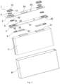
- Fig. 2 is a structural schematic diagram of some embodiments of a secondary battery of the present disclosure, and its exploded view is as shown in Fig. 4 .
- the secondary battery can include a housing 8, an electrode assembly 7, a top cover assembly and a connecting piece 6.
- the electrode assembly 7 is arranged in the housing 8, and includes a first electrode and a second electrode with opposite polarities, for example, the first electrode is a positive electrode, and the second electrode is a negative electrode.
- the first electrode and the second electrode both include a coated part and an uncoated part, and the uncoated part is arranged at an end part, along a length direction of the electrode assembly 7, of the coated area, and forms a tab.
- the top cover assembly is arranged above the electrode assembly 7, and closes the opening of the housing 8.
- the top cover assembly includes: a top cover plate 3, an insulating plate 5 and two electrode terminals 1. A brief description will be given below on each part in the top cover assembly.
- Fig. 3 is a structural schematic diagram of some embodiments of the top cover plate, and the top cover plate 3 is of a thin plate structure, and is arranged on the opening of the housing 8.
- a through hole 31 for drawing out the electric energy of the first electrode and the second electrode is respectively arranged at two ends, along a length direction, on the top cover plate 3, and the shape of the through hole 31 is adapted to the shape of the electrode terminal 1, for example, the through hole 31 can be circular, rectangular or elliptical.
- the top end of the through hole 31 is provided with a sunken part 32, and the electrode terminal 1 is fixed in the sunken part 32, and is arranged at the outer side of the top cover plate 3 and covers the through hole 31.
- An exhaust component 34 and an injecting hole 35 are arranged in the middle area, along a length direction, of the top cover plate 3, and the exhaust component 34 can adopt such existing structure as an anti-explosion piece to release gas in the secondary battery, thereby playing a role of ensuring safety; and the injecting hole 35 is configured to inject electrolyte into the secondary battery, and seal the opening through the seal.
- the insulating plate 5 is arranged on a side of the top cover plate 3 away from the electrode terminal 1, and is arranged between the cover plate 3 and the electrode component 7, the shape of the insulating plate 5 is adapted to the top cover plate 3, to isolate the electrode assembly 7 and the top cover plate 3 and play a role of insulating, for example, the insulating plate 5 can be made of insulating materials like plastics.
- the electrode terminal 1 includes a fixed seat 11 and a terminal plate 12.
- the fixed seat 11 is provided with an accommodating space which is adapted to the shape of the terminal plate 12, to arrange the terminal plate 12 in the accommodating space, and the fixed seat 11 can limit the movement of the terminal plate 12 along a thickness direction.
- the fixed seat 11 can adopt a step columnar structure, an end, with a larger cross section, of the step columnar structure is arranged in the sunken part 32, to fix the electrode terminal 1 on the top cover plate 3.
- the terminal plate 12 is communicated with the inside of the housing 8 through the through hole 31, and a connecting piece 6 is arranged between a lower side of the top cover assembly and the electrode assembly 7, such that the tab 71 at the top part of the electrode assembly 7 is electrically connected with the terminal plate 12 through a connecting piece 6.
- Fig. 4 shows an exploded view of the secondary battery and
- Fig. 5 shows a sectional view
- the connecting piece 6 is provided with a convex part 62, and the convex part 62 extends into the through hole 31 to be electrically connected with the terminal plate 12 of the electrode terminal 1.
- the bottom part of the insulating plate 5 is provided with a concave part 55, and the connecting piece 6 is arranged in the concave part 55.
- the electrode terminal 1 does not need to occupy the space inside the housing 8, and the energy density of the secondary battery can be improved, moreover, the terminal plate 12 is easily processed, and the embodiments given below are all given with such a structural form as an example.
- the electrode terminal 1 can also be stretched into the through hole 31.
- Fig. 6 is an enlarged view of A of Fig. 5 , and is a structural schematic diagram of some embodiments of the top cover assembly. Please refer to Fig. 6 , firstly an embodiment encompassing the improvement ideas of the present disclosure is given below, and subsequently the embodiment of Fig. 6 is described in detail on this basis.
- the top cover assembly of the secondary battery of the present disclosure (“top cover assembly" for short subsequently) includes: a top cover plate 3, an electrode terminal 1, an insulating plate 5, a seal 2 and an insulator 4. Wherein the top cover plate 3 is provided with a through hole 31, the electrode terminal 1 covers the through hole 31, and at least part of the insulating plate 5 is arranged on a side of the top cover plate 3 away from the electrode terminal 1.
- At least part of the seal 2 is arranged between the top cover plate 3 and the terminal plate 12, and at least part of the insulator 4 is arranged between the top cover plate 3 and the insulating plate 5.
- the insulator 4 and the seal 2 jointly enclose the side wall of the through hole 31 and the area, close to the side wall of the through hole 31, of the upper and lower surfaces of the top cover plate 3.
- the insulator 4 and the seal 2 can also only jointly enclose the side wall of the through hole 31 and the area, close to the side wall of the through hole 31, of the upper surface of the top cover plate 3, and the lower surface of the top cover plate 3 is not enclosed.
- the seal 2 can be made of silicone rubber, fluororubber and other materials, and the insulator 4 can adopt PVC, PP, PE or PET and other materials resistant to electrolyte or strong acid.
- the top cover assembly of the present embodiment through adding an insulator 4 between the top cover plate 3 and the insulating plate 5, it can be seen from the section cutting plane which is in parallel with the xy plane that, when the seal 2 is sealed favorably, and the creepage distance between the top cover plate 3 and the terminal plate 12 is the shortest distance along the surface of fixed insulating material between the top cover plate 3 and the terminal plate 12, and at least includes: a matching length section between the insulator 4 as well as the seal 2 and the insulating plate 5, or further includes the length section of the side surface, which is most close to the center of the through hole 31 and which is not in contact with the insulating plate 5.
- the creepage distance can also be constituted by the matching length section between the seal 2 and the insulator 4, the matching length section between the seal 2 and the insulating plate 5, and the side wall section of the seal 2 close to the center of the through hole 31 and uncoated by the insulating plate 5.
- the creepage distance is merely the matching length section between the inner side surface of the sealing ring 2a and the insulating plate 4a. Therefore, as to the top cover assembly of the present disclosure, regardless of the sealing condition of the seal 2, the creepage distance is extended compared with the solution of the related technology.
- the top cover assembly of the present disclosure can increase the creepage distance between the top cover plate 3 and the terminal plate 12, correspondingly, the creepage distance between the top cover plate 3 and the connecting piece 6 is also increased, when the electrode assembly is abnormal and high-voltage (a voltage of greater than 500V) discharge occurs, the safety distance inside the secondary battery is equivalent to be increased, thereby lowering the possibility of such risks as outbreak of fire and explosion of a cell, and improving the safety of the secondary battery.
- the assembly process of the top cover assembly is as follows: firstly, the insulator 4 is fixed onto the top cover plate 3, then the seal 2 is installed, then the electrode terminal 1 is assembled, and the electrode terminal 1 is welded onto the top cover plate 3, and finally the insulating plate 5 is assembled and fixed onto the top cover plate 3.
- the seal 2 is an annular step structure, and includes a first part 21 and a second part 22, and an outline dimension of the second part 22 on a cross section is smaller than that of the first part 21, the outline dimension is the circumferential size.
- the first part 21 is arranged between the top cover plate 3 and the terminal plate 12, and the second part 22 is arranged on a side of the insulator 4 close to the center of the through hole 31, and is in contact with the insulator 4.
- the parts, in contact with other structures, of the seal 2 all adopt interference fit.
- the inner side surface of the second part 22 is flush with the inner side surface of the insulator 4, and such a structure can also increase the creepage distance between the top cover plate 3 and the terminal plate 12.
- the top cover assembly shown in Fig. 6 at least has one of the following advantages:
- the insulator 4 covers an area, close to the through hole 31, of the lower surface of the top cover plate 3, to further increase the creepage distance between the top cover plate 3 and the terminal plate 12.
- the insulator 4 is a step annular structure and includes: a third part 41 and a fourth part 42, an outline dimension of the fourth part 42 on a cross section of is smaller than that of the third part 41.
- the third part 41 is arranged between the top cover plate 3 and the insulating plate 5, an outer surface of the fourth part 42 is fit with a side wall of the through hole 31, and a top surface of the fourth part 42 is not lower than an upper surface, in contact with the seal 2, of the top cover plate 3.
- Such a structure can block the direct discharge gap between the top cover plate 3 and the terminal plate 12 or the connecting piece 6, and is further beneficial for locating the seal 2 and the insulator 4, thereby improving reliability and stability of connection between the two, and still playing a favorable sealing and insulating role after long-term use.
- the top surface of the fourth part 42 is higher than the bottommost surface of the seal 2, and such a structure can extend the creepage distance, block electric gap, and improve operating reliability and safety of the secondary battery.
- the top surface of the fourth part 42 is higher than the bottom surface of the second part 22 of the seal 2, such that the creepage distance includes the width of the sealing interface in which the second part 22 is in contact with the extending part 52, thereby extending the creepage distance.
- a concave-convex matching structure is arranged between the seal 2 and the insulator 4, such that the connection between the two parts is firmer, the connecting stability is improved, and in the assembly process, when the seal 2 is squeezed, the seal 2 is not easily misplaced, thereby ensuring the sealing effect.
- a groove 23 is formed at a bottom surface of the first part 21, and a top end of the fourth part 42 is embedded into the groove 23 to form a concave-convex matching structure.
- the outer side surface of the second part 22 can be taken as a side wall of the groove 23, and after the top end of the fourth part 42 is embedded into the groove 23, the second part 22 can be tightly fit with the fourth part 42, to improve the sealing effect.
- the creepage distance can also be constituted by the matching length section between the seal 2 and the insulator 4, the matching length section between the seal 2 and the insulating plate 5, and the side wall section, close to the center of the through hole 31, of the seal 2.
- the top end of the fourth part 42 is a straight wall section
- the width of the groove 23 is adapted to the thickness of the fourth part 42
- the insulator 4 is of an L-shaped structure on the longitudinal section.
- the structure is easy to assemble.
- the top end of the fourth part 42 is tightly matched with the groove 23 to form sealed connection, to improve the sealing effect to the electrolyte.
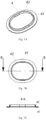
- the stereogram, top view and B-B sectional view of the seal 2 are respectively shown in Fig. 7A, Fig. 7B and Fig. 7C .
- the top end of the fourth part 42 is provided with a bending section 43, the bending section 43 extends towards the side away from the second part 22, and is fit to the upper surface, in contact with the seal 2, of the top cover plate 3, and the seal 2 is of a C-shaped structure on the longitudinal section.
- the bending section 43 and the groove 23 as well as the inner side wall of the fourth part 42 and the outer side wall of the second part 22 are matched tightly to form sealed connection, to improve the sealing effect to the electrolyte.
- the top view and C-C sectional view of the seal 2 are respectively as shown in Fig. 9A and Fig. 9B .
- Such a structure can enlarge the contact area between the insulator 4 and the seal 2 at the connecting point, deformation does not easily occur at the connecting point, and connection firmness and stability are enhanced; moreover, a bending section 43 is added at the top end of the fourth part 42, thereby increasing the strength at the top end of the insulator 4, not easily causing deformation, reducing electrolyte on the creepage distance, reducing current at a constant voltage, and weakening the degree of high-voltage discharge.
- the insulating plate 5 includes a first main body part 51 and an annular extending part 52 which are connected with each other, the first main body part 51 is of a rectangular plateshaped structure, and the size is adapted to that of the top cover plate 3.
- the extending part 52 extends to the through hole 31 and at least part of the extending part 52 is arranged in the through hole 31, and extends towards the electrode terminal 1, and the bottom end of the second part 22 is propped against the top end of the extending part 52.
- the bottom end of the second part 22 is in interference fit with the top end of the extending part 52, to realize sealed connection.
- the width of the surface at which the top end of the extending part 52 is propped against the bottom end of the second part 22 also constitutes a part of the creepage distance, thereby further extending the creepage distance, and improving the operating safety of the secondary battery.
- the top end of the extending part 52 can support the seal 2, such that the extending part 52 is in sealed connection with the second part 22, then the seal 2 is simultaneously squeezed by the electrode terminal 1, the top cover plate 3, the insulator 4 and the extending part 52, thereby realizing a favorable sealing performance, even if the extending part 52 falls, the precompression amount of the seal 2 can also offset part of the falling amount of the extending part 52, to maintain the sealing effect between the seal 2 and the extending part 52, reduce the electrolyte on the creepage distance, and block the electric gap between the top cover plate 3 and the connecting piece 6.
- a contact surface between the extension part 52 and the second part 22 is a horizontal plane.
- Such a structure is easy to be processed, and the extending part 52 can provide a stable supporting force to the second part 22.
- a contact surface between the extension part 52 and the second part 22 is gradually inclined downwards from the inner side to the outer side of the through hole 31, which is not shown in the figure.
- an annular groove is provided on an outer edge of the top end of the extending part 52, and the bottom end of the second part 22 abuts against the annular groove, which is not shown in the figure.
- a part, outside the annular groove, of the top part of the extending part 52 forms a boss, to further provide a lateral pressure to the bottom end of the second part 22, and optimize the sealing effect of the seal 2.
- the third part 41 is arranged between the top cover plate 3 and the insulating plate 5, and a cavity is formed between the third part 41, the top cover plate 3 and the insulating plate 5, for example, a wedge-shaped cavity is formed.
- the creepage distance between the top cover plate 3 and the terminal plate 12 further includes the height of a side wall, away from one end of the fourth part 42, of the third part 41 of the insulator 4.
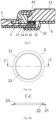
- the third part 41 can be fixed with the bottom part of the top cover plate 3 through a manner of bonding, or as shown in Fig. 10 , a bulge 411 is arranged on the top surface of the third part 41, the top cover plate 3 is provided with a matching hole 33, the bulge 411 is matched with the matching hole 33 to fix the third part 41 and the top cover plate 3, and a plurality of groups of bulges 411 and matching holes 33 can be arranged along a circumferential direction.
- the structures of the top cover plate 3 and the insulating plate 5 do not need to be changed, only the third part 41 needs to be clamped between the top cover plate 3 and the insulating plate 5 through the deformation of the insulating plate 5, thereby avoiding weakening the strength of the top cover plate 3 and the insulating plate 5, moreover, a resilience force produced when the insulating plate 5 is deformed can enable the extending part 52 to be propped tightly against the second part 22 of the seal 2, thereby improving the sealing effect.
- an accommodating groove 54 is arranged on at least one of the top cover plate 3 and the insulating plate 5, the accommodating groove 54 is an annular groove and is arranged at an area close to the side wall of the through hole 31, the third part 41 is arranged in the accommodating groove 54, and the top cover plate 3 is in contact with the insulating plate 5 in an area outside the accommodating groove 54.
- the insulator 4 can be located during assembly, and assembly is facilitated, moreover, when the third part 41 of the insulator 4 is arranged in the accommodating groove 54, the mounting stability can be improved; moreover, the space occupied by the insulator 4 in the housing 8 can be reduced, and the energy density of the battery is improved.
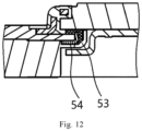
- the accommodating groove 54 is arranged at the bottom part of the top cover plate 3. As shown in Fig. 12 , the accommodating groove 54 is arranged at the top part of the insulating plate 5, and the creepage distance can be increased compared with the condition in which the accommodating groove 54 is arranged at the bottom part of the top cover plate 3.
- the insulating plate 5 includes a first main body part 51 and an annular extending part 52 which are connected with each other, and the extending part 52 extends into the through hole 31 and at least part of the extending part 52 is arranged in the through hole 31, and extends towards the electrode terminal 1.
- the second part 22 is arranged between the insulator 4 and the extending part 52, the extending part 52 is in contact with the second part 22, and the bottom end of the second part 22 is in sealed connection with the insulating plate 5.
- the creepage distance between the top cover plate 3 and the terminal plate 12 at least includes: the length section in which the seal 2 and the insulator 4 are in contact with the insulating plate 5, and the length section, uncoated by the extending part 52, of the inner side surface of the seal 2.
- such a structure can also increase the creepage distance between the top cover plate 3 and the connecting piece 6.
- the extending part 52 is coated at the side surface of the second part 22, and can provide a pressing force to the side surface of the second part 22, such that different areas of the seal 2 are respectively in close contact with the terminal plate 12, the top cover plate 3, the insulating plate 5 and the insulator 4, such that the seal 2 is suffered from a balanced squeezing force, and the sealing effect is improved.
- the contact between the seal 2 and electrolyte can be reduced, thereby preventing swelling of the seal 2, and improving the service life.
- a preset distance exists between the top end of the extending part 52 and the bottom part of the electrode terminal 1, such a structure can provide a pressing force to part of the inner side surface of the seal 2, such that the seal 2 is subjected to a balanced squeezing force, and the sealing effect is improved.
- the top end of the extending part 52 extends to the bottom surface of the electrode terminal 1, and is not in contact with the bottom surface of the electrode terminal 1.
- the extending part 52 in such a structure can provide a pressing force to the whole inner side surface of the seal 2, such that the seal 2 is subjected to a balanced squeezing force, and the sealing effect is improved; moreover, the extending part 52 can prevent contact between the electrolyte and the seal 2, to prevent swelling of the seal 2.
- the top end of the extending part 52 is not in contact with the bottom surface of the electrode terminal 1, to ensure that the bottom part of the electrode terminal 1 can be in close contact with the top part of the seal 2, to improve the sealing performance.
- a bulge 411 is arranged on the top surface of the third part 41, the top cover plate 3 is provided with a matching hole 33, the bulge 411 is matched with the matching hole 33 to fix the third part 41 and the top cover plate 3, a plurality of groups of bulges 411 and matching holes 33 can be arranged along a circumferential direction, the insulator 4 and the top cover plate 3 are connected firmly and do not easily fall off.
- the third part 41 is clamped between the top cover plate 3 and the insulating plate 5, encloses a cavity together with the insulator 4, the top cover plate 3 and the insulating plate 5.
- Fig. 11 differs from Fig. 10 as follows: to ensure firm connection between the insulator 4 and the top cover plate 3, the third part 41 of the insulating part 4 can be connected to the bottom part of the top cover plate 3 through a manner of bonding, and such a structure can lower the processing difficulty of the top cover plate 3 and the insulator 4, and the assembly is convenient.
- Fig. 12 differs from Fig. 10 as follows: an accommodating groove 54 is arranged on the insulating plate 5, the third part 41 is arranged in the accommodating groove 54, and the top cover plate 3 is in contact with the area, outside the accommodating groove 54, of the insulating plate 5.
- a protruding part 53 is arranged at the outer side of the connecting portion between the extending part 52 and the first main body part 51, and the second part 22 extends downwards until the second part 22 is in sealed connection with the protruding part 53.
- the bottom end of the second part 22 is in interference fit with the protruding part 53, to increase the performance of sealed connection between the bottom end of the second part 22 and the insulating plate 5, and reduce the electrolyte on the creepage distance, the resistance can be increased in the absence of electrolyte, so as to reduce current at a constant voltage, and weaken the degree of high-voltage discharge.
- the protruding part 53 includes an oblique plane arranged at the connecting portion between the extending part 52 and the first main body part 51.
- the bottom end of the second part 22 is in interference fit with the oblique plane through compression deformation, and is deformed when the bottom end of the second part 22 is matched with the oblique plane, so as to play a favorable sealing effect.
- the protruding part 53 includes a step arranged at the connecting part between the extending part 52 and the first main body part 51. The bottom end of the second part 22 is in interference fit with the step to improve the sealing performance.
- an insulator 4 is added between the top cover plate 3 and the insulating plate 5, to increase the creepage distance between the top cover plate 3 and the electrode terminal 1, when an electrode assembly 7 is abnormal and high-voltage discharge occurs, the safety distance inside the secondary battery is equivalent to be added, thereby lowering the possibility of such risks of outbreak of fire and explosion of a cell, and improving operating safety of the secondary battery.
Landscapes
- Chemical & Material Sciences (AREA)
- Chemical Kinetics & Catalysis (AREA)
- Electrochemistry (AREA)
- General Chemical & Material Sciences (AREA)
- Engineering & Computer Science (AREA)
- Materials Engineering (AREA)
- Manufacturing & Machinery (AREA)
- Connection Of Batteries Or Terminals (AREA)
- Sealing Battery Cases Or Jackets (AREA)
Description
- The present disclosure is based upon and claims priority to
Chinese Patent Application No. 201910281152.6, filed on April 9, 2019 - The present disclosure relates to the technical field of batteries, in particular to a top cover assembly of a secondary battery and a secondary battery.
- Owing to such advantages as high energy density, high power density, multiple cycles and long storage time, lithium-ion batteries are widely used in electric vehicles. During the actual use of the lithium-ion batteries, it is found that a cell will have such safety risks as outbreak of fire and explosion.
- Patent application
CN 109 428 017 describes a secondary battery and a battery module. The secondary battery comprises a shell, an electrode assembly, a top cover assembly, a wiring board and a sealing part, wherein the shell has an opening; the electrode assembly comprises a first pole piece, a second pole piece and a partition plate arranged between the first pole piece and the second pole piece; the top cover assembly comprises a top cover plate and a first electrode terminal, wherein the top cover plate covers the opening and is provided with an electrode lead-out hole; the first electrode terminal comprises a terminal plate, wherein the terminal plate is located on one side of the top cover plate and covers the electrode lead-out hole; the wiring board comprises a main body part and an extension part connected with the main body part, and the main body part is located on one side, away from the terminal plate, of the top cover plate and is connected with the first pole piece; the extension part extends into the electrode lead-out hole and is connected with the first electrode terminal; and the sealing part is arranged between the top cover plate and the wiring board and surrounds the extension part so as to seal the electrode lead-out hole. The space utilization rate inside the secondary battery shell can be improved, so that the energy density of the secondary battery is improved, so as to prevent electrolyte leakage in the secondary battery shell. - Patent Application
CN 207 233 789 describes a secondary cell and battery module. The secondary cell includes: a casing having an opening, an electrode subassembly including first pole piece, second pole piece and baffle, the top cap subassembly, including a plate and electrode terminals, the plate covers the opening and has the electrode lead, and electrode terminals include the terminal block, the lower part insulating part is located one side of the terminal block. - Patent application
CN 108 767 143 describes a header component of a secondary battery. The header component comprises a top plate provided with an electrode outlet; an electrode terminal that comprises a terminal plate positioned on one side of the top plate and covering the electrode outlet; a first fixing piece at least partially encircling the terminal plate, so as to fix the electrode terminal on the first fixing piece; and a second fixing piece comprising a main body and a first connection part connected with the main body and extending towards the direction that is far away from the terminal plate, wherein the main body is joined with the first fixing piece, and the first connection part is joined with the top plate. One or more purposes of simplifying the structure of the top plate component, increasing the stability of connection between the post and the top plate, and enhancing the airtightness of the top plate component can be achieved. - According to an aspect of the present disclosure, a top cover assembly of a secondary battery is provided, and the top cover assembly includes:
- a top cover plate, provided with a through hole;
- an electrode terminal, covering the through hole;
- an insulating plate, wherein at least part of the insulating plate is arranged on a side of the top cover plate away from the electrode terminal;
- a seal, wherein at least part of the seal is arranged between the top cover plate and the electrode terminal; and
- an insulator, wherein at least part of the insulator is arranged between the top cover plate and the insulating plate;
- wherein the insulator and the seal at least jointly surround a side wall of the through hole and an area of an upper surface of the top cover plate close to the through hole.
- In some embodiments, the seal is of an annular structure, including:
- a first part, arranged between the top cover plate and the electrode terminal; and
- a second part, wherein an outline dimension of the second part on a cross section is smaller than that of the first part, and the second part is arranged on a side of the insulator close to the center of the through hole and is in contact with the insulator.
- A concave-convex matching structure is arranged between the seal and the insulator.
- In some embodiments, the insulator further covers an area of an lower surface of the top cover plate close to the through hole.
- In some embodiments, the insulator is of an annular structure, including:
- a third part, arranged between the top cover plate and the insulating plate; and
- a fourth part, wherein an outline dimension of the fourth part on a cross section is smaller than that of the third part, an outer surface of the fourth part is fit with the side wall of the through hole, and a top surface of the fourth part is not lower than the upper surface of the top cover plate in contact with the seal.
- In some embodiments, wherein the insulator is of an annular structure and includes:
- a third part, arranged between the top cover plate and an insulating plate; and
- a fourth part, wherein an outline dimension of the fourth part on a cross section is smaller than that of the third part, an outer surface of the fourth part is fit with the side wall of the through hole, and a top surface of the fourth part is higher than a bottommost surface of the seal.
- In some embodiments, the seal is of an annular structure and includes: a first part and a second part, wherein the first part is arranged between the top cover plate and the electrode terminal, an outline dimension of the second part on a cross section is smaller than that of the first part, and the second part is arranged on a side of the insulator close to a center of the through hole and is in contact with the insulator;
- the insulator is of an annular structure and includes: a third part and a fourth part, wherein the third part is arranged between the top cover plate and the insulating plate; and an outline dimension of the fourth part on a cross section is smaller than that of the third part, and the outer surface of the fourth part is fit with the side wall of the through hole; and
- wherein a groove is formed at a bottom surface of the first part, and a top end of the fourth part is embedded into the groove to form the concave-convex matching structure.
- In some embodiments, the top end of the fourth part is a straight wall section; or
the top end of the fourth part is provided with a bending section, and the bending section extends towards a side away from the second part and is fit to the upper surface of the top cover plate in contact with the seal. - In some embodiments, the insulating plate includes a first main body part and an annular extending part which are connected with each other, the extending part extends to the through hole and at least part of the extending part is arranged in the through hole, and a bottom end of the second part abuts against a top end of the extending part.
- In some embodiments, the insulating plate includes a first main body part and an annular extending part which are connected with each other, the extending part extends to the through hole and at least part of the extending part is arranged in the through hole, the second part is arranged between the insulator and the extending part, and the extending part is in contact with the second part.
- In some embodiments, the top end of the extending part extends to a bottom surface of the electrode terminal and is not in contact with the bottom surface of the electrode terminal.
- In some embodiments, a protruding part is arranged at an outer side of a connecting portion between the extending part and the first main body part, and the second part extends downwards until the second part is in sealed connection with the protruding part.
- In some embodiments, the third part is provided with a bulge, the top cover plate is provided with a matching hole, and the bulge is matched with the matching hole to fix the third part and the top cover plate.
- In some embodiments, an accommodating groove is arranged on at least one of the top cover plate and the insulating plate, the third part is arranged in the accommodating groove, and the top cover plate is in contact with the insulating plate in the area outside the accommodating groove.
- According to another aspect of the present disclosure, a secondary battery is provided, and the secondary battery includes:
- a housing;
- an electrode assembly, arranged in the housing; and
- the top cover assembly of the secondary battery according to the above embodiments, arranged above the electrode assembly and closes the housing.
- The drawings described herein provide a further understanding of the present disclosure, and constitute a part of the present disclosure. The exemplary embodiments of the present disclosure and descriptions thereof are used for explaining the present disclosure, rather than constituting an improper limitation to the present disclosure. In the drawings:
-
Fig. 1 is a structural schematic diagram of a secondary battery in the related technology; -
Fig. 2 is a structural schematic diagram of some embodiments of a secondary battery of the present disclosure; -
Fig. 3 is a structural schematic diagram of a bottom part of a top cover plate in a top cover assembly of a secondary battery of the present disclosure; -
Fig. 4 is an exploded view of some embodiments of a secondary battery of the present disclosure; -
Fig. 5 is a sectional view of some embodiments of the secondary battery of the present disclosure; -
Fig. 6 is an enlarged view of A inFig. 5 ; -
Fig. 7A, Fig. 7B and Fig. 7C are respectively a space diagram, a top view and a B-B sectional view of an insulator inFig. 6 ; -
Fig. 8 is a structural schematic diagram of some embodiments in which an extending section is arranged on a top end of an insulator in the top cover assembly of the secondary battery of the present disclosure; -
Fig. 9A and Fig. 9B are respectively a top view and a C-C sectional view of an insulator inFig. 8 ; -
Fig. 10 is a structural schematic diagram of some embodiments in which an extending part of an insulating plate and a second part of a seal are arranged in a staggered manner in a top cover assembly of a secondary battery of the present disclosure; -
Fig. 11 is a structural schematic diagram of some other embodiments in which an extending part of an insulating plate and a second part of a seal are arranged in a staggered manner in a top cover assembly of a secondary battery of the present disclosure; -
Fig. 12 is a structural schematic diagram of some embodiments in which an accommodating groove is arranged on the insulating plate in a top cover assembly of a secondary battery of the present disclosure. - 1a, electrode terminal; 2a, sealing ring; 3a, top cover plate; 4a, insulating plate; 5a, connecting piece; 1, electrode terminal; 11, fixed seat; 12, terminal plate; 2, seal; 21, first part; 22, second part; 23, groove; 3, top cover plate; 31, through hole; 32, concave part; 33; matching hole; 34, exhaust component; 35, injecting hole; 4, insulator; 41, third part; 411, bulge; 42, fourth part; 43, bending section; 5, insulating plate; 51, first main body part; 52, extending part; 53, protruding part; 54, accommodating groove; 55, concave part; 6, connecting piece; 61, second main body part; 62, convex part; 7, electrode assembly; 71, tab; 8, housing.
- The present disclosure will be described in detail below. In the following paragraphs, different aspects of the embodiments are defined in more details. Each aspect thus defined can be combined with one or more of any other aspects, unless it is expressly stated that each aspect cannot be combined with other aspects. Especially, any characteristic which is deemed to be preferable or beneficial can be combined with one or more other characteristics which are deemed to be preferable or beneficial.
- Such terms as "first" and "second" in the present disclosure are merely for the convenience of description, to distinguish different components with the same name, but do not represent precedence or subordination.
- In addition, when one element is called to be "on" another element, the element can be directly arranged on the other element, or can be indirectly arranged on the other element and one or more intermediate elements are inserted therebetween. In addition, when one element is called to be "connected to" another element, the element can be directly connected to the other element, or can be indirectly connected to the other element and one or more intermediate elements can be inserted therebetween. In the following text, the same reference numerals represent the same element.
- In order to clearly describe each orientation in the following embodiments, each direction of a secondary battery is defined in a coordinate system in
Fig. 2 , wherein x direction represents a length direction of the secondary battery; y direction is vertical to the x direction in a horizontal plane, and represents a width direction of the secondary battery; and z direction is vertical to a plane formed by x direction and y direction, and represents a height direction of the secondary battery. - Based on the definition of orientations, the description of such orientation or positional relationship indicated by such terms as "up", "down", "top", "bottom", "inner" and "outer" is merely for the convenience of the description of the present disclosure, rather than indicating or implying that the device referred to must be located in a certain orientation or must be constructed or operated in a certain orientation, therefore, the terms cannot be understood as a limitation to the protection scope of the present disclosure.
- The inventor found that, the voltage of a complete vehicle system is about 300V to 900V. When a cell is abnormal, an internal circuit or a fusing part will be disconnected, at this time, the cell will be subjected to a reverse high voltage of the system, however, since the internal safety distance is not sufficient, therefore, the cell will have such safety risks as outbreak of fire or explosion.
- A related technology known by the inventor is as shown in
Fig. 1 , and the top cover assembly of the battery includes: anelectrode terminal 1a, a sealingring 2a, atop cover plate 3a and an insulatingplate 4a, wherein thetop cover plate 3a is provided with a through hole, theelectrode terminal 1a covers the through hole above thetop cover plate 3a, the insulatingplate 4a is arranged below thetop cover plate 3a, the insulatingplate 4a is provided with an extending part which penetrates through the through hole and extends to the bottom of theelectrode terminal 1a, and thesealing ring 2a is arranged in a space enclosed by theelectrode terminal 1a, thetop cover plate 3a and the top end of the extending part. The connectingpiece 5a protrudes upwards at the through hole to conduct the electrode assembly and theelectrode terminal 1a. However, the safety risk of such a battery is higher during actual use. - Through analysis, the inventor found that the reasons of lower safety of the secondary battery in the related technology are as follows:
- Firstly, as shown in
Fig. 1 , a creepage distance between thetop cover plate 3a and theelectrode terminal 1a is merely a length section in which thesealing ring 2a is in contact with the top end of the extending part of the insulatingplate 4a, such as the position indicated by the bold lines inFig. 1 , the creepage distance is very short, the safety risk is high under a reverse high voltage, and such phenomenon as outbreak of fire or explosion may occur. - Secondly, the extending part of the insulating
plate 4a will fall with the following reasons: fuse plastics are arranged on a positive connecting piece, such that a gap is formed between the horizontal part of the positive connecting piece and the insulatingplate 4a; on a side of the negative connecting piece, a gap will also be reserved between the horizontal part of the negative connecting piece and the insulatingplate 4a, if h2=h1 inFig. 1 , due to a manufacturing tolerance, a convex hull of the connectingpiece 5a may not reach theelectrode terminal 1a, thereby leading to poor welding, therefore, h2>h1 is actually required, to ensure firm welding between the connectingpiece 5a and theelectrode terminal 1a, therefore, a gap Δ h=h2-h1 will be formed between the insulatingplate 4a and the horizontal part of the connectingpiece 5a. - Meanwhile, the part, arranged in the through hole, of the insulating
plate 4a is equivalent to a cantilever beam, therefore, the extending part easily drops, then the insulatingplate 4a moves downwards, and a gap is formed between the top part of the extending part and thesealing ring 2a, thereby leading to the following problems: 1, an electric gap will be formed between thetop cover plate 3a and theelectrode terminal 1a and between thetop cover plate 3a and the connectingpiece 5a, however, the electric gap is small, and the breakdown risk is high, so the safety is poor; and 2, electrolyte will enter into the sealing interface between the sealingring 2a and the insulatingplate 4a, the electrolyte on the creepage path is increased, the resistance is reduced, and when a voltage of greater than 500V is applied between theelectrode terminal 1a and thetop cover plate 3a, safety risk exists. - Based on the above problems, in the present disclosure, the secondary battery is improved to improve the safety of the secondary battery, and the main improvement idea lies in increasing the creepage distance and increasing the electric gap. Therefore, embodiments of the present disclosure provide a top cover assembly of a secondary battery and a secondary battery, to improve safety of the secondary battery during high-voltage discharge.
- As to the top cover assembly of the secondary battery in an embodiment of the present disclosure, through adding an insulator between the top cover plate and the insulating plate, the creepage distance between the top cover plate and the electrode terminal can be increased, when an electrode assembly is abnormal and high-voltage discharge occurs, the safety distance inside the secondary battery is equivalent to be added, thereby lowering the possibility of such risks of outbreak of fire and explosion of a cell, and improving operating safety of the secondary battery.
-
Fig. 2 is a structural schematic diagram of some embodiments of a secondary battery of the present disclosure, and its exploded view is as shown inFig. 4 . The secondary battery can include ahousing 8, anelectrode assembly 7, a top cover assembly and a connectingpiece 6. - The
electrode assembly 7 is arranged in thehousing 8, and includes a first electrode and a second electrode with opposite polarities, for example, the first electrode is a positive electrode, and the second electrode is a negative electrode. The first electrode and the second electrode both include a coated part and an uncoated part, and the uncoated part is arranged at an end part, along a length direction of theelectrode assembly 7, of the coated area, and forms a tab. - The top cover assembly is arranged above the
electrode assembly 7, and closes the opening of thehousing 8. The top cover assembly includes: atop cover plate 3, an insulatingplate 5 and twoelectrode terminals 1. A brief description will be given below on each part in the top cover assembly. -
Fig. 3 is a structural schematic diagram of some embodiments of the top cover plate, and thetop cover plate 3 is of a thin plate structure, and is arranged on the opening of thehousing 8. A throughhole 31 for drawing out the electric energy of the first electrode and the second electrode is respectively arranged at two ends, along a length direction, on thetop cover plate 3, and the shape of the throughhole 31 is adapted to the shape of theelectrode terminal 1, for example, the throughhole 31 can be circular, rectangular or elliptical. The top end of the throughhole 31 is provided with asunken part 32, and theelectrode terminal 1 is fixed in thesunken part 32, and is arranged at the outer side of thetop cover plate 3 and covers the throughhole 31. Anexhaust component 34 and an injectinghole 35 are arranged in the middle area, along a length direction, of thetop cover plate 3, and theexhaust component 34 can adopt such existing structure as an anti-explosion piece to release gas in the secondary battery, thereby playing a role of ensuring safety; and the injectinghole 35 is configured to inject electrolyte into the secondary battery, and seal the opening through the seal. - As shown in
Fig. 4 , at least part of the insulatingplate 5 is arranged on a side of thetop cover plate 3 away from theelectrode terminal 1, and is arranged between thecover plate 3 and theelectrode component 7, the shape of the insulatingplate 5 is adapted to thetop cover plate 3, to isolate theelectrode assembly 7 and thetop cover plate 3 and play a role of insulating, for example, the insulatingplate 5 can be made of insulating materials like plastics. - Still refer to
Fig. 4 , to simplify the structure of theelectrode terminal 1, theelectrode terminal 1 includes a fixedseat 11 and aterminal plate 12. Wherein the fixedseat 11 is provided with an accommodating space which is adapted to the shape of theterminal plate 12, to arrange theterminal plate 12 in the accommodating space, and the fixedseat 11 can limit the movement of theterminal plate 12 along a thickness direction. The fixedseat 11 can adopt a step columnar structure, an end, with a larger cross section, of the step columnar structure is arranged in thesunken part 32, to fix theelectrode terminal 1 on thetop cover plate 3. - The
terminal plate 12 is communicated with the inside of thehousing 8 through the throughhole 31, and a connectingpiece 6 is arranged between a lower side of the top cover assembly and theelectrode assembly 7, such that thetab 71 at the top part of theelectrode assembly 7 is electrically connected with theterminal plate 12 through a connectingpiece 6.Fig. 4 shows an exploded view of the secondary battery andFig. 5 shows a sectional view, the connectingpiece 6 is provided with aconvex part 62, and theconvex part 62 extends into the throughhole 31 to be electrically connected with theterminal plate 12 of theelectrode terminal 1. The bottom part of the insulatingplate 5 is provided with aconcave part 55, and the connectingpiece 6 is arranged in theconcave part 55. Through such a structure, theelectrode terminal 1 does not need to occupy the space inside thehousing 8, and the energy density of the secondary battery can be improved, moreover, theterminal plate 12 is easily processed, and the embodiments given below are all given with such a structural form as an example. Optionally, theelectrode terminal 1 can also be stretched into the throughhole 31. - After the overall structure of the secondary battery is given, the improvement points of the present disclosure will be described as an emphasis below.
-
Fig. 6 is an enlarged view of A ofFig. 5 , and is a structural schematic diagram of some embodiments of the top cover assembly. Please refer toFig. 6 , firstly an embodiment encompassing the improvement ideas of the present disclosure is given below, and subsequently the embodiment ofFig. 6 is described in detail on this basis. The top cover assembly of the secondary battery of the present disclosure ("top cover assembly" for short subsequently) includes: atop cover plate 3, anelectrode terminal 1, an insulatingplate 5, aseal 2 and aninsulator 4. Wherein thetop cover plate 3 is provided with a throughhole 31, theelectrode terminal 1 covers the throughhole 31, and at least part of the insulatingplate 5 is arranged on a side of thetop cover plate 3 away from theelectrode terminal 1. At least part of theseal 2 is arranged between thetop cover plate 3 and theterminal plate 12, and at least part of theinsulator 4 is arranged between thetop cover plate 3 and the insulatingplate 5. Theinsulator 4 and theseal 2 jointly enclose the side wall of the throughhole 31 and the area, close to the side wall of the throughhole 31, of the upper and lower surfaces of thetop cover plate 3. Optionally, theinsulator 4 and theseal 2 can also only jointly enclose the side wall of the throughhole 31 and the area, close to the side wall of the throughhole 31, of the upper surface of thetop cover plate 3, and the lower surface of thetop cover plate 3 is not enclosed. Theseal 2 can be made of silicone rubber, fluororubber and other materials, and theinsulator 4 can adopt PVC, PP, PE or PET and other materials resistant to electrolyte or strong acid. - As to the top cover assembly of the present embodiment, through adding an
insulator 4 between thetop cover plate 3 and the insulatingplate 5, it can be seen from the section cutting plane which is in parallel with the xy plane that, when theseal 2 is sealed favorably, and the creepage distance between thetop cover plate 3 and theterminal plate 12 is the shortest distance along the surface of fixed insulating material between thetop cover plate 3 and theterminal plate 12, and at least includes: a matching length section between theinsulator 4 as well as theseal 2 and the insulatingplate 5, or further includes the length section of the side surface, which is most close to the center of the throughhole 31 and which is not in contact with the insulatingplate 5. When a gap exists between theseal 2 and theinsulator 4, the creepage distance can also be constituted by the matching length section between theseal 2 and theinsulator 4, the matching length section between theseal 2 and the insulatingplate 5, and the side wall section of theseal 2 close to the center of the throughhole 31 and uncoated by the insulatingplate 5. In the solutions of related technologies, the creepage distance is merely the matching length section between the inner side surface of the sealingring 2a and the insulatingplate 4a. Therefore, as to the top cover assembly of the present disclosure, regardless of the sealing condition of theseal 2, the creepage distance is extended compared with the solution of the related technology. - Therefore, the top cover assembly of the present disclosure can increase the creepage distance between the
top cover plate 3 and theterminal plate 12, correspondingly, the creepage distance between thetop cover plate 3 and the connectingpiece 6 is also increased, when the electrode assembly is abnormal and high-voltage (a voltage of greater than 500V) discharge occurs, the safety distance inside the secondary battery is equivalent to be increased, thereby lowering the possibility of such risks as outbreak of fire and explosion of a cell, and improving the safety of the secondary battery. - The assembly process of the top cover assembly is as follows: firstly, the
insulator 4 is fixed onto thetop cover plate 3, then theseal 2 is installed, then theelectrode terminal 1 is assembled, and theelectrode terminal 1 is welded onto thetop cover plate 3, and finally the insulatingplate 5 is assembled and fixed onto thetop cover plate 3. - Still refer to
Fig. 6 , theseal 2 is an annular step structure, and includes afirst part 21 and asecond part 22, and an outline dimension of thesecond part 22 on a cross section is smaller than that of thefirst part 21, the outline dimension is the circumferential size. Wherein thefirst part 21 is arranged between thetop cover plate 3 and theterminal plate 12, and thesecond part 22 is arranged on a side of theinsulator 4 close to the center of the throughhole 31, and is in contact with theinsulator 4. In the actual structure, the parts, in contact with other structures, of theseal 2 all adopt interference fit. - Alternatively, the inner side surface of the
second part 22 is flush with the inner side surface of theinsulator 4, and such a structure can also increase the creepage distance between thetop cover plate 3 and theterminal plate 12. - The top cover assembly shown in
Fig. 6 at least has one of the following advantages: - 1. the inner side surface of the
seal 2 exceeds the inner side surface of theinsulator 4, such that theseal 2 and theinsulator 4 are staggered with each other, and part of theinsulator 4 is enclosed, thereby further increasing the creepage distance, with the increased part being the thickness of the bottom part of thesecond part 22, and improving the operating safety of the secondary battery. - 2. an overlapping part is arranged between the connecting end parts of the
seal 2 and theinsulator 4, thereby increasing the sealing performance to the electrolyte, reducing the electrolyte on the creepage distance, increasing the resistance in the absence of electrolyte, reducing current at a constant voltage, and weakening the degree of high-voltage discharge. - 3. an overlapping part exists between the connecting end parts of the
seal 2 and theinsulator 4, thereby blocking the electric gap between thetop cover plate 3 and theterminal plate 12, and the gap between thetop cover plate 3 and the connectingpiece 6, reducing the breakdown risk, with the electric gap being the shortest distance between two conducting parts in the air, and increasing insulating reliability. Blocking the electric gap means to isolate originally continuous environmental medium (such as air or electrolyte and other liquid media) between two conductors, such that the environmental medium is no longer continuous, and two conductors can no longer be broken down. When the electric gap is blocked, the electric gap can be deemed as being enlarged to infinity. - 4. such a structure can increase the stability of connection between the
seal 2 and theinsulator 4, and can still play a favorable sealing and insulating role after long-term use. - In some embodiments, the
insulator 4 covers an area, close to the throughhole 31, of the lower surface of thetop cover plate 3, to further increase the creepage distance between thetop cover plate 3 and theterminal plate 12. - Still refer to
Fig. 6 , theinsulator 4 is a step annular structure and includes: athird part 41 and afourth part 42, an outline dimension of thefourth part 42 on a cross section of is smaller than that of thethird part 41. Wherein thethird part 41 is arranged between thetop cover plate 3 and the insulatingplate 5, an outer surface of thefourth part 42 is fit with a side wall of the throughhole 31, and a top surface of thefourth part 42 is not lower than an upper surface, in contact with theseal 2, of thetop cover plate 3. Such a structure can block the direct discharge gap between thetop cover plate 3 and theterminal plate 12 or the connectingpiece 6, and is further beneficial for locating theseal 2 and theinsulator 4, thereby improving reliability and stability of connection between the two, and still playing a favorable sealing and insulating role after long-term use. - Still refer to
Fig. 6 , the top surface of thefourth part 42 is higher than the bottommost surface of theseal 2, and such a structure can extend the creepage distance, block electric gap, and improve operating reliability and safety of the secondary battery. Specifically, the top surface of thefourth part 42 is higher than the bottom surface of thesecond part 22 of theseal 2, such that the creepage distance includes the width of the sealing interface in which thesecond part 22 is in contact with the extendingpart 52, thereby extending the creepage distance. - On this basis, a concave-convex matching structure is arranged between the
seal 2 and theinsulator 4, such that the connection between the two parts is firmer, the connecting stability is improved, and in the assembly process, when theseal 2 is squeezed, theseal 2 is not easily misplaced, thereby ensuring the sealing effect. - Specifically, a
groove 23 is formed at a bottom surface of thefirst part 21, and a top end of thefourth part 42 is embedded into thegroove 23 to form a concave-convex matching structure. For example, the outer side surface of thesecond part 22 can be taken as a side wall of thegroove 23, and after the top end of thefourth part 42 is embedded into thegroove 23, thesecond part 22 can be tightly fit with thefourth part 42, to improve the sealing effect. - Please refer to
Fig. 6 , when a gap exists between theseal 2 and theinsulator 4, the creepage distance can also be constituted by the matching length section between theseal 2 and theinsulator 4, the matching length section between theseal 2 and the insulatingplate 5, and the side wall section, close to the center of the throughhole 31, of theseal 2. - In a structural form, as shown in
Fig. 6 , the top end of thefourth part 42 is a straight wall section, the width of thegroove 23 is adapted to the thickness of thefourth part 42, and theinsulator 4 is of an L-shaped structure on the longitudinal section. The structure is easy to assemble. The top end of thefourth part 42 is tightly matched with thegroove 23 to form sealed connection, to improve the sealing effect to the electrolyte. The stereogram, top view and B-B sectional view of theseal 2 are respectively shown inFig. 7A, Fig. 7B and Fig. 7C . - In another structural form, as shown in
Fig. 8 , the top end of thefourth part 42 is provided with abending section 43, the bendingsection 43 extends towards the side away from thesecond part 22, and is fit to the upper surface, in contact with theseal 2, of thetop cover plate 3, and theseal 2 is of a C-shaped structure on the longitudinal section. The bendingsection 43 and thegroove 23 as well as the inner side wall of thefourth part 42 and the outer side wall of thesecond part 22 are matched tightly to form sealed connection, to improve the sealing effect to the electrolyte. The top view and C-C sectional view of theseal 2 are respectively as shown inFig. 9A and Fig. 9B . - Such a structure can enlarge the contact area between the
insulator 4 and theseal 2 at the connecting point, deformation does not easily occur at the connecting point, and connection firmness and stability are enhanced; moreover, abending section 43 is added at the top end of thefourth part 42, thereby increasing the strength at the top end of theinsulator 4, not easily causing deformation, reducing electrolyte on the creepage distance, reducing current at a constant voltage, and weakening the degree of high-voltage discharge. - As shown in
Fig. 6 , the insulatingplate 5 includes a firstmain body part 51 and an annular extendingpart 52 which are connected with each other, the firstmain body part 51 is of a rectangular plateshaped structure, and the size is adapted to that of thetop cover plate 3. The extendingpart 52 extends to the throughhole 31 and at least part of the extendingpart 52 is arranged in the throughhole 31, and extends towards theelectrode terminal 1, and the bottom end of thesecond part 22 is propped against the top end of the extendingpart 52. Preferably, the bottom end of thesecond part 22 is in interference fit with the top end of the extendingpart 52, to realize sealed connection. - In such a structure, the width of the surface at which the top end of the extending
part 52 is propped against the bottom end of thesecond part 22 also constitutes a part of the creepage distance, thereby further extending the creepage distance, and improving the operating safety of the secondary battery. Moreover, the top end of the extendingpart 52 can support theseal 2, such that the extendingpart 52 is in sealed connection with thesecond part 22, then theseal 2 is simultaneously squeezed by theelectrode terminal 1, thetop cover plate 3, theinsulator 4 and the extendingpart 52, thereby realizing a favorable sealing performance, even if the extendingpart 52 falls, the precompression amount of theseal 2 can also offset part of the falling amount of the extendingpart 52, to maintain the sealing effect between theseal 2 and the extendingpart 52, reduce the electrolyte on the creepage distance, and block the electric gap between thetop cover plate 3 and the connectingpiece 6. - Aiming at the structure in which the bottom end of the
second part 22 is propped against the top end of the extendingpart 52, three implementing manners are given below. - In one structural form, as shown in
Fig. 6 , a contact surface between theextension part 52 and thesecond part 22 is a horizontal plane. Such a structure is easy to be processed, and the extendingpart 52 can provide a stable supporting force to thesecond part 22. - In another structural form, a contact surface between the
extension part 52 and thesecond part 22 is gradually inclined downwards from the inner side to the outer side of the throughhole 31, which is not shown in the figure. When the extendingpart 52 in the structure provides a supporting force to thesecond part 22, a lateral pressure can be provided to the bottom end of thesecond part 22, and the sealing effect of theseal 2 is optimized. - In still another structural form, an annular groove is provided on an outer edge of the top end of the extending
part 52, and the bottom end of thesecond part 22 abuts against the annular groove, which is not shown in the figure. In such a structure, a part, outside the annular groove, of the top part of the extendingpart 52 forms a boss, to further provide a lateral pressure to the bottom end of thesecond part 22, and optimize the sealing effect of theseal 2. - Still refer to
Fig. 6 , thethird part 41 is arranged between thetop cover plate 3 and the insulatingplate 5, and a cavity is formed between thethird part 41, thetop cover plate 3 and the insulatingplate 5, for example, a wedge-shaped cavity is formed. For such a structure, the creepage distance between thetop cover plate 3 and theterminal plate 12 further includes the height of a side wall, away from one end of thefourth part 42, of thethird part 41 of theinsulator 4. - Wherein the
third part 41 can be fixed with the bottom part of thetop cover plate 3 through a manner of bonding, or as shown inFig. 10 , abulge 411 is arranged on the top surface of thethird part 41, thetop cover plate 3 is provided with amatching hole 33, thebulge 411 is matched with the matchinghole 33 to fix thethird part 41 and thetop cover plate 3, and a plurality of groups ofbulges 411 and matchingholes 33 can be arranged along a circumferential direction. - Through such a structure, the structures of the
top cover plate 3 and the insulatingplate 5 do not need to be changed, only thethird part 41 needs to be clamped between thetop cover plate 3 and the insulatingplate 5 through the deformation of the insulatingplate 5, thereby avoiding weakening the strength of thetop cover plate 3 and the insulatingplate 5, moreover, a resilience force produced when the insulatingplate 5 is deformed can enable the extendingpart 52 to be propped tightly against thesecond part 22 of theseal 2, thereby improving the sealing effect. - In other structural forms, an
accommodating groove 54 is arranged on at least one of thetop cover plate 3 and the insulatingplate 5, theaccommodating groove 54 is an annular groove and is arranged at an area close to the side wall of the throughhole 31, thethird part 41 is arranged in theaccommodating groove 54, and thetop cover plate 3 is in contact with the insulatingplate 5 in an area outside theaccommodating groove 54. Through such a structure, theinsulator 4 can be located during assembly, and assembly is facilitated, moreover, when thethird part 41 of theinsulator 4 is arranged in theaccommodating groove 54, the mounting stability can be improved; moreover, the space occupied by theinsulator 4 in thehousing 8 can be reduced, and the energy density of the battery is improved. - As shown in
Fig. 8 , theaccommodating groove 54 is arranged at the bottom part of thetop cover plate 3. As shown inFig. 12 , theaccommodating groove 54 is arranged at the top part of the insulatingplate 5, and the creepage distance can be increased compared with the condition in which theaccommodating groove 54 is arranged at the bottom part of thetop cover plate 3. - In some other embodiments, as shown in
Fig. 10 to Fig. 12 , the insulatingplate 5 includes a firstmain body part 51 and an annular extendingpart 52 which are connected with each other, and the extendingpart 52 extends into the throughhole 31 and at least part of the extendingpart 52 is arranged in the throughhole 31, and extends towards theelectrode terminal 1. Different fromFig. 6 , thesecond part 22 is arranged between theinsulator 4 and the extendingpart 52, the extendingpart 52 is in contact with thesecond part 22, and the bottom end of thesecond part 22 is in sealed connection with the insulatingplate 5. The creepage distance between thetop cover plate 3 and theterminal plate 12 at least includes: the length section in which theseal 2 and theinsulator 4 are in contact with the insulatingplate 5, and the length section, uncoated by the extendingpart 52, of the inner side surface of theseal 2. Correspondingly, such a structure can also increase the creepage distance between thetop cover plate 3 and the connectingpiece 6. - In such a structure, the extending
part 52 is coated at the side surface of thesecond part 22, and can provide a pressing force to the side surface of thesecond part 22, such that different areas of theseal 2 are respectively in close contact with theterminal plate 12, thetop cover plate 3, the insulatingplate 5 and theinsulator 4, such that theseal 2 is suffered from a balanced squeezing force, and the sealing effect is improved. Moreover, when the extendingpart 52 is coated at the side surface of thesecond part 22, the contact between theseal 2 and electrolyte can be reduced, thereby preventing swelling of theseal 2, and improving the service life. - Still refer to
Fig. 10 , a preset distance exists between the top end of the extendingpart 52 and the bottom part of theelectrode terminal 1, such a structure can provide a pressing force to part of the inner side surface of theseal 2, such that theseal 2 is subjected to a balanced squeezing force, and the sealing effect is improved. - As shown in
Fig. 12 , the top end of the extendingpart 52 extends to the bottom surface of theelectrode terminal 1, and is not in contact with the bottom surface of theelectrode terminal 1. The extendingpart 52 in such a structure can provide a pressing force to the whole inner side surface of theseal 2, such that theseal 2 is subjected to a balanced squeezing force, and the sealing effect is improved; moreover, the extendingpart 52 can prevent contact between the electrolyte and theseal 2, to prevent swelling of theseal 2. In addition, the top end of the extendingpart 52 is not in contact with the bottom surface of theelectrode terminal 1, to ensure that the bottom part of theelectrode terminal 1 can be in close contact with the top part of theseal 2, to improve the sealing performance. - Still refer to
Fig. 10 , to ensure firm connection between theinsulator 4 and thetop cover plate 3, abulge 411 is arranged on the top surface of thethird part 41, thetop cover plate 3 is provided with amatching hole 33, thebulge 411 is matched with the matchinghole 33 to fix thethird part 41 and thetop cover plate 3, a plurality of groups ofbulges 411 and matchingholes 33 can be arranged along a circumferential direction, theinsulator 4 and thetop cover plate 3 are connected firmly and do not easily fall off. Thethird part 41 is clamped between thetop cover plate 3 and the insulatingplate 5, encloses a cavity together with theinsulator 4, thetop cover plate 3 and the insulatingplate 5. -
Fig. 11 differs fromFig. 10 as follows: to ensure firm connection between theinsulator 4 and thetop cover plate 3, thethird part 41 of theinsulating part 4 can be connected to the bottom part of thetop cover plate 3 through a manner of bonding, and such a structure can lower the processing difficulty of thetop cover plate 3 and theinsulator 4, and the assembly is convenient. -
Fig. 12 differs fromFig. 10 as follows: an accommodatinggroove 54 is arranged on the insulatingplate 5, thethird part 41 is arranged in theaccommodating groove 54, and thetop cover plate 3 is in contact with the area, outside theaccommodating groove 54, of the insulatingplate 5. - Still refer to
Fig. 12 , a protrudingpart 53 is arranged at the outer side of the connecting portion between the extendingpart 52 and the firstmain body part 51, and thesecond part 22 extends downwards until thesecond part 22 is in sealed connection with the protrudingpart 53. The bottom end of thesecond part 22 is in interference fit with the protrudingpart 53, to increase the performance of sealed connection between the bottom end of thesecond part 22 and the insulatingplate 5, and reduce the electrolyte on the creepage distance, the resistance can be increased in the absence of electrolyte, so as to reduce current at a constant voltage, and weaken the degree of high-voltage discharge. - For example, in the structure as shown in
Fig. 12 , the protrudingpart 53 includes an oblique plane arranged at the connecting portion between the extendingpart 52 and the firstmain body part 51. The bottom end of thesecond part 22 is in interference fit with the oblique plane through compression deformation, and is deformed when the bottom end of thesecond part 22 is matched with the oblique plane, so as to play a favorable sealing effect. Or, the protrudingpart 53 includes a step arranged at the connecting part between the extendingpart 52 and the firstmain body part 51. The bottom end of thesecond part 22 is in interference fit with the step to improve the sealing performance. - In the top cover assembly of the present embodiment of the present disclosure, an
insulator 4 is added between thetop cover plate 3 and the insulatingplate 5, to increase the creepage distance between thetop cover plate 3 and theelectrode terminal 1, when anelectrode assembly 7 is abnormal and high-voltage discharge occurs, the safety distance inside the secondary battery is equivalent to be added, thereby lowering the possibility of such risks of outbreak of fire and explosion of a cell, and improving operating safety of the secondary battery. - A brief introduction is given above on the top cover assembly of the secondary battery and the secondary battery provided in the present disclosure. Specific embodiments are used in the text to elaborate the principles and embodiments of the present disclosure, and the description of the above embodiments merely helps to understand the method and its core idea of the present disclosure. However, the invention is defined by the appended claims.
Claims (14)
- A top cover assembly of a secondary battery, comprising:a top cover plate (3), provided with a through hole (31);an electrode terminal (1), covering the through hole (31);an insulating plate (5), wherein at least part of the insulating plate (5) is arranged on a side of the top cover plate (3) away from the electrode terminal (1);a seal (2), wherein at least part of the seal (2) is arranged between the top cover plate (3) and the electrode terminal (1); andan insulator (4), wherein at least part of the insulator (4) is arranged between the top cover plate (3) and the insulating plate (5);wherein the insulator (4) and the seal (2) at least jointly enclose a side wall of the through hole (31) and an area, close to the through hole (31), on an upper surface of the top cover plate (3),characterized in that a concave-convex matching structure is arranged between the seal (2) and the insulator (4).
- The top cover assembly of a secondary battery according to claim 1, wherein the seal (2) is of an annular structure, comprising:a first part (21), arranged between the top cover plate (3) and the electrode terminal (1); anda second part (22), wherein an outline dimension of the second part (22) on a cross section is smaller than that of the first part (21), and the second part (22) is arranged on a side of the insulator (4) close to the center of the through hole (31) and is in contact with the insulator (4).
- The top cover assembly of a secondary battery according to claim 1 or 2, wherein the insulator (4) covers an area, close to the through hole (31), of the lower surface of the top cover plate (3).
- The top cover assembly of a secondary battery according to any one of claims 1-3, wherein the insulator (4) is of an annular structure, comprising:a third part (41), arranged between the top cover plate (3) and the insulating plate (5); anda fourth part (42), wherein an outline dimension of the fourth part (42) on a cross section is smaller than that of the third part (41), an outer surface of the fourth part (42) is fit with the side wall of the through hole (31), and a top surface of the fourth part (42) is not lower than an upper surface, in contact with the seal (2), of the top cover plate (3).
- The top cover assembly of a secondary battery according to any one of claims 1-3, wherein the insulator (4) is of an annular structure and comprises:a third part (41), arranged between the top cover plate (3) and an insulating plate (5); anda fourth part (42), wherein an outline dimension of the fourth part (42) on a cross section is smaller than that of the third part (41), an outer surface of the fourth part (42) is fit with the side wall of the through hole (31), and a top surface of the fourth part (42) is higher than a bottommost surface of the seal (2).
- The top cover assembly of a secondary battery according to claim 1, whereinthe seal (2) is of an annular structure and comprises: a first part (21) and a second part (22), wherein the first part (21) is arranged between the top cover plate (3) and the electrode terminal (1), an outline dimension of the second part (22) on a cross section is smaller than that of the first part (21), and the second part (22) is arranged on a side of the insulator (4) close to a center of the through hole (31) and is in contact with the insulator (4);the insulator (4) is of an annular structure and comprises: a third part (41) and a fourth part (42), wherein the third part (41) is arranged between the top cover plate (3) and the insulating plate (5); and an outline dimension of the fourth part (42) on a cross section is smaller than that of the third part (41), and the outer surface of the fourth part (42) is fit with the side wall of the through hole (31); andwherein a groove (23) is formed at a bottom surface of the first part (21), and a top end of the fourth part (42) is embedded into the groove (23) to form the concave-convex matching structure.
- The top cover assembly of a secondary battery according to claim 6, whereinthe top end of the fourth part (42) is a straight wall section; orthe top end of the fourth part (42) is provided with a bending section (43), and the bending section (43) extends towards a side away from the second part (22) and is fit to the upper surface of the top cover plate (3) in contact with the seal (2).
- The top cover assembly of a secondary battery according to claim 2, wherein the insulating plate (5) comprises a first main body part (51) and an annular extending part (52) which are connected with each other, the extending part (52) extends to the through hole (31) and at least part of the extending part (52) is arranged in the through hole (31), and a bottom end of the second part (22) abuts against a top end of the extending part (52).
- The top cover assembly of a secondary battery according to claim 2 or 8, wherein the insulating plate (5) comprises a first main body part (51) and an annular extending part (52) which are connected with each other, the extending part (52) extends to the through hole (31) and at least part of the extending part (52) is arranged in the through hole (31), the second part (22) is arranged between the insulator (4) and the extending part (52), and the extending part (52) is in contact with the second part (22).
- The top cover assembly of a secondary battery according to claim 9, wherein the top end of the extending part (52) extends to a bottom surface of the electrode terminal (1) and is not in contact with the bottom surface of the electrode terminal (1).
- The top cover assembly of a secondary battery according to claim 9 or 10, wherein a protruding part (53) is arranged at an outer side of a connecting portion between the extending part (52) and the first main body part (51), and the second part (22) extends downwards until the second part (22) is in sealed connection with the protruding part (53).
- The top cover assembly of a secondary battery according to claim 4 or 5, wherein the third part (41) is provided with a bulge (411), the top cover plate (3) is provided with a matching hole (33), and the bulge (411) is matched with the matching hole (33) to fix the third part (41) and the top cover plate (3)
- The top cover assembly of a secondary battery according to claim 4 or 5, wherein an accommodating groove (54) is arranged on at least one of the top cover plate (3) and the insulating plate (5), the third part (41) is arranged in the accommodating groove (54), and the top cover plate (3) is in contact with the area, outside the accommodating groove (54), of the insulating plate (5).
- A secondary battery, comprising:a housing (8);an electrode assembly (7), arranged in the housing (8); andthe top cover assembly of the secondary battery according to any one of claims 1-13, arranged above the electrode assembly (7) to close the housing (8).
Applications Claiming Priority (2)
| Application Number | Priority Date | Filing Date | Title |
|---|---|---|---|
| CN201910281152.6A CN110176558B (en) | 2019-04-09 | 2019-04-09 | Secondary battery top cap subassembly and secondary battery |
| PCT/CN2020/080879 WO2020207238A1 (en) | 2019-04-09 | 2020-03-24 | Secondary battery top cover assembly and secondary battery |
Publications (3)
| Publication Number | Publication Date |
|---|---|
| EP3790072A1 EP3790072A1 (en) | 2021-03-10 |
| EP3790072A4 EP3790072A4 (en) | 2021-08-11 |
| EP3790072B1 true EP3790072B1 (en) | 2024-04-10 |
Family
ID=67689644
Family Applications (1)
| Application Number | Title | Priority Date | Filing Date |
|---|---|---|---|
| EP20788020.4A Active EP3790072B1 (en) | 2019-04-09 | 2020-03-24 | Secondary battery top cover assembly and secondary battery |
Country Status (4)
| Country | Link |
|---|---|
| US (1) | US12334570B2 (en) |
| EP (1) | EP3790072B1 (en) |
| CN (1) | CN110176558B (en) |
| WO (1) | WO2020207238A1 (en) |
Families Citing this family (18)
| Publication number | Priority date | Publication date | Assignee | Title |
|---|---|---|---|---|
| CN110176558B (en) * | 2019-04-09 | 2024-04-19 | 宁德时代新能源科技股份有限公司 | Secondary battery top cap subassembly and secondary battery |
| CN110880563B (en) * | 2019-10-10 | 2021-12-14 | 宁德新能源科技有限公司 | Battery case assembly and battery having the same |
| JP7481431B2 (en) * | 2019-12-24 | 2024-05-10 | 瑞浦蘭鈞能源股分有限公司 | Power battery top cover and power battery |
| CN120300426A (en) | 2020-04-17 | 2025-07-11 | 宁德时代新能源科技股份有限公司 | End cap assembly, battery cell, battery module and device |
| CN212161863U (en) * | 2020-05-27 | 2020-12-15 | 宁德时代新能源科技股份有限公司 | Secondary battery, battery module, and device using secondary battery as power source |
| EP3944403B1 (en) | 2020-05-27 | 2022-11-02 | Contemporary Amperex Technology Co., Limited | Secondary battery, battery module, and device using secondary battery as power source |
| EP4050711B1 (en) | 2020-12-31 | 2024-01-17 | Contemporary Amperex Technology Co., Limited | End cover assembly, battery cell, battery, and apparatus and method for manufacturing battery cell |
| CN113346170B (en) * | 2021-05-31 | 2023-05-02 | 宁德新能源科技有限公司 | Battery and electronic device |
| CN113675510B (en) * | 2021-08-17 | 2023-01-24 | 厦门海辰储能科技股份有限公司 | The end connection structure of the battery cell, the battery cell, and the power battery |
| CN217485645U (en) * | 2022-04-11 | 2022-09-23 | 宁德时代新能源科技股份有限公司 | End cap assemblies, battery cells, batteries and powered devices |
| EP4475292A4 (en) * | 2022-05-16 | 2025-06-04 | Contemporary Amperex Technology (Hong Kong) Limited | End cover assembly of battery cell, battery cell, battery, and electric device |
| CN114784428A (en) * | 2022-05-17 | 2022-07-22 | 湖北亿纬动力有限公司 | Top cap subassembly and secondary cell |
| CN115663412B (en) * | 2022-11-11 | 2023-03-28 | 深圳海润新能源科技有限公司 | Terminal subassembly, top cap subassembly, energy memory and consumer |
| USD1060219S1 (en) * | 2023-03-03 | 2025-02-04 | Contemporary Amperex Technology Co., Limited | Battery |
| CN116826321B (en) * | 2023-08-04 | 2024-08-27 | 江西百思利新能源科技股份有限公司 | Secondary battery pole assembly, manufacturing process thereof and secondary battery top cover |
| JP1778254S (en) * | 2023-08-23 | 2024-08-21 | Battery, Electric | |
| CN221861777U (en) * | 2023-10-20 | 2024-10-18 | 宁德时代新能源科技股份有限公司 | End cap assembly, battery cell, battery and electrical device |
| CN118040082B (en) * | 2024-02-22 | 2024-09-20 | 惠州市典名新能源科技有限公司 | High-safety lithium battery |
Family Cites Families (22)
| Publication number | Priority date | Publication date | Assignee | Title |
|---|---|---|---|---|
| KR19990031352A (en) * | 1997-10-10 | 1999-05-06 | 손욱 | Battery safety device |
| CN1303718C (en) * | 1999-03-26 | 2007-03-07 | 松下电器产业株式会社 | laminated sheet packaged battery |
| US6673489B2 (en) * | 2001-12-28 | 2004-01-06 | Quallion Llc | Electric battery assembly and method of manufacture |
| KR100807029B1 (en) * | 2006-03-28 | 2008-02-25 | 삼성에스디아이 주식회사 | Secondary battery |
| JP2009087613A (en) * | 2007-09-28 | 2009-04-23 | Sanyo Electric Co Ltd | Square battery |
| JP5790987B2 (en) | 2010-05-17 | 2015-10-07 | 株式会社Gsユアサ | Battery and battery manufacturing method |
| US9331312B2 (en) * | 2011-10-12 | 2016-05-03 | Samsung Sdi Co., Ltd. | Secondary battery |
| KR101682286B1 (en) * | 2012-06-29 | 2016-12-05 | 도요타지도샤가부시키가이샤 | battery |
| KR20150089831A (en) * | 2014-01-28 | 2015-08-05 | 삼성에스디아이 주식회사 | Battery Pack |
| US10320208B2 (en) * | 2014-05-12 | 2019-06-11 | Kabushiki Kaisha Toyota Jidoshokki | Electricity storage device |
| JP6731176B2 (en) * | 2016-01-21 | 2020-07-29 | 株式会社Gsユアサ | Electric storage element and method for manufacturing electric storage element |
| CN105845851B (en) * | 2016-06-07 | 2018-07-17 | 宁德时代新能源科技股份有限公司 | Power battery top cover and power battery thereof |
| CN105870375B (en) * | 2016-06-07 | 2018-07-10 | 宁德时代新能源科技股份有限公司 | Power battery top cap and power battery |
| US11367933B2 (en) * | 2017-01-25 | 2022-06-21 | Sanyo Electric Co., Ltd. | Secondary battery |
| CN109428017B (en) * | 2017-08-30 | 2020-11-20 | 宁德时代新能源科技股份有限公司 | Secondary battery and battery module |
| CN108428824B (en) * | 2017-08-30 | 2024-04-16 | 宁德时代新能源科技股份有限公司 | Secondary battery and battery module |
| CN207233789U (en) * | 2017-08-30 | 2018-04-13 | 宁德时代新能源科技股份有限公司 | Secondary cell and battery modules |
| CN109659453B (en) | 2017-10-10 | 2020-09-15 | 宁德时代新能源科技股份有限公司 | Secondary cell's top cap subassembly and secondary cell |
| US10763466B2 (en) * | 2018-03-09 | 2020-09-01 | Contemporary Amperex Technology Co., Limited | Top cap assembly of a secondary battery, and secondary battery |
| CN208690318U (en) | 2018-09-26 | 2019-04-02 | 宁德时代新能源科技股份有限公司 | A top cover assembly of a battery cell and a battery cell |
| CN209658243U (en) * | 2019-04-09 | 2019-11-19 | 宁德时代新能源科技股份有限公司 | Secondary cell cap assembly and secondary cell |
| CN110176558B (en) | 2019-04-09 | 2024-04-19 | 宁德时代新能源科技股份有限公司 | Secondary battery top cap subassembly and secondary battery |
-
2019
- 2019-04-09 CN CN201910281152.6A patent/CN110176558B/en active Active
-
2020
- 2020-03-24 WO PCT/CN2020/080879 patent/WO2020207238A1/en not_active Ceased
- 2020-03-24 US US15/733,847 patent/US12334570B2/en active Active
- 2020-03-24 EP EP20788020.4A patent/EP3790072B1/en active Active
Also Published As
| Publication number | Publication date |
|---|---|
| CN110176558B (en) | 2024-04-19 |
| WO2020207238A1 (en) | 2020-10-15 |
| US20210234219A1 (en) | 2021-07-29 |
| CN110176558A (en) | 2019-08-27 |
| EP3790072A1 (en) | 2021-03-10 |
| EP3790072A4 (en) | 2021-08-11 |
| US12334570B2 (en) | 2025-06-17 |
Similar Documents
| Publication | Publication Date | Title |
|---|---|---|
| US12334570B2 (en) | Top cover assembly of secondary battery and secondary battery | |
| CN110176557B (en) | Secondary battery and top cover assembly thereof | |
| CN209658246U (en) | Cap assembly and secondary cell | |
| EP2228852B1 (en) | Rechargeable battery comprising current collecting plates with improved structure | |
| US9203060B2 (en) | Secondary battery | |
| CN100418262C (en) | secondary battery | |
| US8592079B2 (en) | Rechargeable battery | |
| EP3321998A1 (en) | Secondary battery | |
| EP2768069A1 (en) | Battery module | |
| JP5203729B2 (en) | Secondary battery and battery module | |
| CN108767143A (en) | Secondary cell's top cap subassembly and secondary cell | |
| CN209658243U (en) | Secondary cell cap assembly and secondary cell | |
| CN104241560A (en) | Rechargeable battery | |
| CN216213745U (en) | Square secondary battery's top cap and secondary battery | |
| CN103840115A (en) | Rechargeable battery | |
| CN112436214A (en) | Cylindrical battery negative end cover and cylindrical battery thereof | |
| KR101142682B1 (en) | Battery pack | |
| KR20130091533A (en) | Secondary battery | |
| EP2736099A1 (en) | Rechargeable battery | |
| CN209658242U (en) | Secondary battery and its top cover assembly | |
| KR20090021482A (en) | Secondary battery | |
| CN222673258U (en) | Cylindrical battery cell and electric equipment | |
| CN224191050U (en) | Battery cover plate and battery | |
| CN223680335U (en) | Secondary battery and battery pack | |
| KR20120103111A (en) | Cap assemblies and secondary cells having the same |
Legal Events
| Date | Code | Title | Description |
|---|---|---|---|
| STAA | Information on the status of an ep patent application or granted ep patent |
Free format text: STATUS: THE INTERNATIONAL PUBLICATION HAS BEEN MADE |
|
| PUAI | Public reference made under article 153(3) epc to a published international application that has entered the european phase |
Free format text: ORIGINAL CODE: 0009012 |
|
| STAA | Information on the status of an ep patent application or granted ep patent |
Free format text: STATUS: REQUEST FOR EXAMINATION WAS MADE |
|
| 17P | Request for examination filed |
Effective date: 20201130 |
|
| AK | Designated contracting states |
Kind code of ref document: A1 Designated state(s): AL AT BE BG CH CY CZ DE DK EE ES FI FR GB GR HR HU IE IS IT LI LT LU LV MC MK MT NL NO PL PT RO RS SE SI SK SM TR |
|
| AX | Request for extension of the european patent |
Extension state: BA ME |
|
| A4 | Supplementary search report drawn up and despatched |
Effective date: 20210708 |
|
| RIC1 | Information provided on ipc code assigned before grant |
Ipc: H01M 50/147 20210101AFI20210702BHEP Ipc: H01M 50/155 20210101ALI20210702BHEP Ipc: H01M 50/183 20210101ALI20210702BHEP Ipc: H01M 50/572 20210101ALI20210702BHEP |
|
| DAV | Request for validation of the european patent (deleted) | ||
| DAX | Request for extension of the european patent (deleted) | ||
| REG | Reference to a national code |
Ref country code: DE Ref legal event code: R079 Free format text: PREVIOUS MAIN CLASS: H01M0002040000 Ipc: H01M0050150000 Ref document number: 602020028855 Country of ref document: DE |
|
| GRAP | Despatch of communication of intention to grant a patent |
Free format text: ORIGINAL CODE: EPIDOSNIGR1 |
|
| RIC1 | Information provided on ipc code assigned before grant |
Ipc: H01M 50/557 20210101ALI20230927BHEP Ipc: H01M 50/188 20210101ALI20230927BHEP Ipc: H01M 50/15 20210101AFI20230927BHEP |
|
| STAA | Information on the status of an ep patent application or granted ep patent |
Free format text: STATUS: GRANT OF PATENT IS INTENDED |
|
| INTG | Intention to grant announced |
Effective date: 20231102 |
|
| GRAS | Grant fee paid |
Free format text: ORIGINAL CODE: EPIDOSNIGR3 |
|
| GRAA | (expected) grant |
Free format text: ORIGINAL CODE: 0009210 |
|
| STAA | Information on the status of an ep patent application or granted ep patent |
Free format text: STATUS: THE PATENT HAS BEEN GRANTED |
|
| P01 | Opt-out of the competence of the unified patent court (upc) registered |
Effective date: 20240204 |
|
| AK | Designated contracting states |
Kind code of ref document: B1 Designated state(s): AL AT BE BG CH CY CZ DE DK EE ES FI FR GB GR HR HU IE IS IT LI LT LU LV MC MK MT NL NO PL PT RO RS SE SI SK SM TR |
|
| REG | Reference to a national code |
Ref country code: GB Ref legal event code: FG4D |
|
| REG | Reference to a national code |
Ref country code: CH Ref legal event code: EP |
|
| REG | Reference to a national code |
Ref country code: DE Ref legal event code: R096 Ref document number: 602020028855 Country of ref document: DE |
|
| REG | Reference to a national code |
Ref country code: IE Ref legal event code: FG4D |
|
| REG | Reference to a national code |
Ref country code: LT Ref legal event code: MG9D |
|
| REG | Reference to a national code |
Ref country code: NL Ref legal event code: MP Effective date: 20240410 |
|
| REG | Reference to a national code |
Ref country code: DE Ref legal event code: R081 Ref document number: 602020028855 Country of ref document: DE Owner name: CONTEMPORARY AMPEREX TECHNOLOGY (HONG KONG) LI, HK Free format text: FORMER OWNER: CONTEMPORARY AMPEREX TECHNOLOGY CO., LIMITED, NINGDE CITY, FUJIAN, CN |
|
| REG | Reference to a national code |
Ref country code: AT Ref legal event code: MK05 Ref document number: 1675873 Country of ref document: AT Kind code of ref document: T Effective date: 20240410 |
|
| PG25 | Lapsed in a contracting state [announced via postgrant information from national office to epo] |
Ref country code: NL Free format text: LAPSE BECAUSE OF FAILURE TO SUBMIT A TRANSLATION OF THE DESCRIPTION OR TO PAY THE FEE WITHIN THE PRESCRIBED TIME-LIMIT Effective date: 20240410 |
|
| REG | Reference to a national code |
Ref country code: GB Ref legal event code: 732E Free format text: REGISTERED BETWEEN 20240829 AND 20240904 |
|
| PG25 | Lapsed in a contracting state [announced via postgrant information from national office to epo] |
Ref country code: NL Free format text: LAPSE BECAUSE OF FAILURE TO SUBMIT A TRANSLATION OF THE DESCRIPTION OR TO PAY THE FEE WITHIN THE PRESCRIBED TIME-LIMIT Effective date: 20240410 |
|
| RAP2 | Party data changed (patent owner data changed or rights of a patent transferred) |
Owner name: CONTEMPORARY AMPEREX TECHNOLOGY(HONG KONG) LIMITED |
|
| PG25 | Lapsed in a contracting state [announced via postgrant information from national office to epo] |
Ref country code: IS Free format text: LAPSE BECAUSE OF FAILURE TO SUBMIT A TRANSLATION OF THE DESCRIPTION OR TO PAY THE FEE WITHIN THE PRESCRIBED TIME-LIMIT Effective date: 20240810 |
|
| PG25 | Lapsed in a contracting state [announced via postgrant information from national office to epo] |
Ref country code: BG Free format text: LAPSE BECAUSE OF FAILURE TO SUBMIT A TRANSLATION OF THE DESCRIPTION OR TO PAY THE FEE WITHIN THE PRESCRIBED TIME-LIMIT Effective date: 20240410 |
|
| PG25 | Lapsed in a contracting state [announced via postgrant information from national office to epo] |
Ref country code: FI Free format text: LAPSE BECAUSE OF FAILURE TO SUBMIT A TRANSLATION OF THE DESCRIPTION OR TO PAY THE FEE WITHIN THE PRESCRIBED TIME-LIMIT Effective date: 20240410 Ref country code: HR Free format text: LAPSE BECAUSE OF FAILURE TO SUBMIT A TRANSLATION OF THE DESCRIPTION OR TO PAY THE FEE WITHIN THE PRESCRIBED TIME-LIMIT Effective date: 20240410 |
|
| PG25 | Lapsed in a contracting state [announced via postgrant information from national office to epo] |
Ref country code: GR Free format text: LAPSE BECAUSE OF FAILURE TO SUBMIT A TRANSLATION OF THE DESCRIPTION OR TO PAY THE FEE WITHIN THE PRESCRIBED TIME-LIMIT Effective date: 20240711 |
|
| PG25 | Lapsed in a contracting state [announced via postgrant information from national office to epo] |
Ref country code: PT Free format text: LAPSE BECAUSE OF FAILURE TO SUBMIT A TRANSLATION OF THE DESCRIPTION OR TO PAY THE FEE WITHIN THE PRESCRIBED TIME-LIMIT Effective date: 20240812 |
|
| PG25 | Lapsed in a contracting state [announced via postgrant information from national office to epo] |
Ref country code: ES Free format text: LAPSE BECAUSE OF FAILURE TO SUBMIT A TRANSLATION OF THE DESCRIPTION OR TO PAY THE FEE WITHIN THE PRESCRIBED TIME-LIMIT Effective date: 20240410 |
|
| PG25 | Lapsed in a contracting state [announced via postgrant information from national office to epo] |
Ref country code: AT Free format text: LAPSE BECAUSE OF FAILURE TO SUBMIT A TRANSLATION OF THE DESCRIPTION OR TO PAY THE FEE WITHIN THE PRESCRIBED TIME-LIMIT Effective date: 20240410 |
|
| PG25 | Lapsed in a contracting state [announced via postgrant information from national office to epo] |
Ref country code: PL Free format text: LAPSE BECAUSE OF FAILURE TO SUBMIT A TRANSLATION OF THE DESCRIPTION OR TO PAY THE FEE WITHIN THE PRESCRIBED TIME-LIMIT Effective date: 20240410 |
|
| PG25 | Lapsed in a contracting state [announced via postgrant information from national office to epo] |
Ref country code: LV Free format text: LAPSE BECAUSE OF FAILURE TO SUBMIT A TRANSLATION OF THE DESCRIPTION OR TO PAY THE FEE WITHIN THE PRESCRIBED TIME-LIMIT Effective date: 20240410 |
|
| PG25 | Lapsed in a contracting state [announced via postgrant information from national office to epo] |
Ref country code: PT Free format text: LAPSE BECAUSE OF FAILURE TO SUBMIT A TRANSLATION OF THE DESCRIPTION OR TO PAY THE FEE WITHIN THE PRESCRIBED TIME-LIMIT Effective date: 20240812 Ref country code: PL Free format text: LAPSE BECAUSE OF FAILURE TO SUBMIT A TRANSLATION OF THE DESCRIPTION OR TO PAY THE FEE WITHIN THE PRESCRIBED TIME-LIMIT Effective date: 20240410 Ref country code: NO Free format text: LAPSE BECAUSE OF FAILURE TO SUBMIT A TRANSLATION OF THE DESCRIPTION OR TO PAY THE FEE WITHIN THE PRESCRIBED TIME-LIMIT Effective date: 20240710 Ref country code: LV Free format text: LAPSE BECAUSE OF FAILURE TO SUBMIT A TRANSLATION OF THE DESCRIPTION OR TO PAY THE FEE WITHIN THE PRESCRIBED TIME-LIMIT Effective date: 20240410 Ref country code: IS Free format text: LAPSE BECAUSE OF FAILURE TO SUBMIT A TRANSLATION OF THE DESCRIPTION OR TO PAY THE FEE WITHIN THE PRESCRIBED TIME-LIMIT Effective date: 20240810 Ref country code: HR Free format text: LAPSE BECAUSE OF FAILURE TO SUBMIT A TRANSLATION OF THE DESCRIPTION OR TO PAY THE FEE WITHIN THE PRESCRIBED TIME-LIMIT Effective date: 20240410 Ref country code: GR Free format text: LAPSE BECAUSE OF FAILURE TO SUBMIT A TRANSLATION OF THE DESCRIPTION OR TO PAY THE FEE WITHIN THE PRESCRIBED TIME-LIMIT Effective date: 20240711 Ref country code: FI Free format text: LAPSE BECAUSE OF FAILURE TO SUBMIT A TRANSLATION OF THE DESCRIPTION OR TO PAY THE FEE WITHIN THE PRESCRIBED TIME-LIMIT Effective date: 20240410 Ref country code: ES Free format text: LAPSE BECAUSE OF FAILURE TO SUBMIT A TRANSLATION OF THE DESCRIPTION OR TO PAY THE FEE WITHIN THE PRESCRIBED TIME-LIMIT Effective date: 20240410 Ref country code: BG Free format text: LAPSE BECAUSE OF FAILURE TO SUBMIT A TRANSLATION OF THE DESCRIPTION OR TO PAY THE FEE WITHIN THE PRESCRIBED TIME-LIMIT Effective date: 20240410 Ref country code: AT Free format text: LAPSE BECAUSE OF FAILURE TO SUBMIT A TRANSLATION OF THE DESCRIPTION OR TO PAY THE FEE WITHIN THE PRESCRIBED TIME-LIMIT Effective date: 20240410 Ref country code: RS Free format text: LAPSE BECAUSE OF FAILURE TO SUBMIT A TRANSLATION OF THE DESCRIPTION OR TO PAY THE FEE WITHIN THE PRESCRIBED TIME-LIMIT Effective date: 20240710 |
|
| REG | Reference to a national code |
Ref country code: DE Ref legal event code: R097 Ref document number: 602020028855 Country of ref document: DE |
|
| PG25 | Lapsed in a contracting state [announced via postgrant information from national office to epo] |
Ref country code: DK Free format text: LAPSE BECAUSE OF FAILURE TO SUBMIT A TRANSLATION OF THE DESCRIPTION OR TO PAY THE FEE WITHIN THE PRESCRIBED TIME-LIMIT Effective date: 20240410 |
|
| PG25 | Lapsed in a contracting state [announced via postgrant information from national office to epo] |
Ref country code: EE Free format text: LAPSE BECAUSE OF FAILURE TO SUBMIT A TRANSLATION OF THE DESCRIPTION OR TO PAY THE FEE WITHIN THE PRESCRIBED TIME-LIMIT Effective date: 20240410 |
|
| PG25 | Lapsed in a contracting state [announced via postgrant information from national office to epo] |
Ref country code: CZ Free format text: LAPSE BECAUSE OF FAILURE TO SUBMIT A TRANSLATION OF THE DESCRIPTION OR TO PAY THE FEE WITHIN THE PRESCRIBED TIME-LIMIT Effective date: 20240410 |
|
| PG25 | Lapsed in a contracting state [announced via postgrant information from national office to epo] |
Ref country code: RO Free format text: LAPSE BECAUSE OF FAILURE TO SUBMIT A TRANSLATION OF THE DESCRIPTION OR TO PAY THE FEE WITHIN THE PRESCRIBED TIME-LIMIT Effective date: 20240410 Ref country code: SK Free format text: LAPSE BECAUSE OF FAILURE TO SUBMIT A TRANSLATION OF THE DESCRIPTION OR TO PAY THE FEE WITHIN THE PRESCRIBED TIME-LIMIT Effective date: 20240410 |
|
| PG25 | Lapsed in a contracting state [announced via postgrant information from national office to epo] |
Ref country code: SM Free format text: LAPSE BECAUSE OF FAILURE TO SUBMIT A TRANSLATION OF THE DESCRIPTION OR TO PAY THE FEE WITHIN THE PRESCRIBED TIME-LIMIT Effective date: 20240410 |
|
| PG25 | Lapsed in a contracting state [announced via postgrant information from national office to epo] |
Ref country code: SM Free format text: LAPSE BECAUSE OF FAILURE TO SUBMIT A TRANSLATION OF THE DESCRIPTION OR TO PAY THE FEE WITHIN THE PRESCRIBED TIME-LIMIT Effective date: 20240410 Ref country code: SK Free format text: LAPSE BECAUSE OF FAILURE TO SUBMIT A TRANSLATION OF THE DESCRIPTION OR TO PAY THE FEE WITHIN THE PRESCRIBED TIME-LIMIT Effective date: 20240410 Ref country code: RO Free format text: LAPSE BECAUSE OF FAILURE TO SUBMIT A TRANSLATION OF THE DESCRIPTION OR TO PAY THE FEE WITHIN THE PRESCRIBED TIME-LIMIT Effective date: 20240410 Ref country code: EE Free format text: LAPSE BECAUSE OF FAILURE TO SUBMIT A TRANSLATION OF THE DESCRIPTION OR TO PAY THE FEE WITHIN THE PRESCRIBED TIME-LIMIT Effective date: 20240410 Ref country code: DK Free format text: LAPSE BECAUSE OF FAILURE TO SUBMIT A TRANSLATION OF THE DESCRIPTION OR TO PAY THE FEE WITHIN THE PRESCRIBED TIME-LIMIT Effective date: 20240410 Ref country code: CZ Free format text: LAPSE BECAUSE OF FAILURE TO SUBMIT A TRANSLATION OF THE DESCRIPTION OR TO PAY THE FEE WITHIN THE PRESCRIBED TIME-LIMIT Effective date: 20240410 |
|
| PG25 | Lapsed in a contracting state [announced via postgrant information from national office to epo] |
Ref country code: IT Free format text: LAPSE BECAUSE OF FAILURE TO SUBMIT A TRANSLATION OF THE DESCRIPTION OR TO PAY THE FEE WITHIN THE PRESCRIBED TIME-LIMIT Effective date: 20240410 |
|
| PLBE | No opposition filed within time limit |
Free format text: ORIGINAL CODE: 0009261 |
|
| STAA | Information on the status of an ep patent application or granted ep patent |
Free format text: STATUS: NO OPPOSITION FILED WITHIN TIME LIMIT |
|
| 26N | No opposition filed |
Effective date: 20250113 |
|
| PG25 | Lapsed in a contracting state [announced via postgrant information from national office to epo] |
Ref country code: SI Free format text: LAPSE BECAUSE OF FAILURE TO SUBMIT A TRANSLATION OF THE DESCRIPTION OR TO PAY THE FEE WITHIN THE PRESCRIBED TIME-LIMIT Effective date: 20240410 |
|
| PG25 | Lapsed in a contracting state [announced via postgrant information from national office to epo] |
Ref country code: SE Free format text: LAPSE BECAUSE OF FAILURE TO SUBMIT A TRANSLATION OF THE DESCRIPTION OR TO PAY THE FEE WITHIN THE PRESCRIBED TIME-LIMIT Effective date: 20240410 |
|
| PG25 | Lapsed in a contracting state [announced via postgrant information from national office to epo] |
Ref country code: MC Free format text: LAPSE BECAUSE OF FAILURE TO SUBMIT A TRANSLATION OF THE DESCRIPTION OR TO PAY THE FEE WITHIN THE PRESCRIBED TIME-LIMIT Effective date: 20240410 |
|
| REG | Reference to a national code |
Ref country code: CH Ref legal event code: H13 Free format text: ST27 STATUS EVENT CODE: U-0-0-H10-H13 (AS PROVIDED BY THE NATIONAL OFFICE) Effective date: 20251023 |
|
| PG25 | Lapsed in a contracting state [announced via postgrant information from national office to epo] |
Ref country code: LU Free format text: LAPSE BECAUSE OF NON-PAYMENT OF DUE FEES Effective date: 20250324 |
|
| REG | Reference to a national code |
Ref country code: BE Ref legal event code: MM Effective date: 20250331 |
|
| PG25 | Lapsed in a contracting state [announced via postgrant information from national office to epo] |
Ref country code: BE Free format text: LAPSE BECAUSE OF NON-PAYMENT OF DUE FEES Effective date: 20250331 |
|
| PG25 | Lapsed in a contracting state [announced via postgrant information from national office to epo] |
Ref country code: CH Free format text: LAPSE BECAUSE OF NON-PAYMENT OF DUE FEES Effective date: 20250331 |
|
| PG25 | Lapsed in a contracting state [announced via postgrant information from national office to epo] |
Ref country code: IE Free format text: LAPSE BECAUSE OF NON-PAYMENT OF DUE FEES Effective date: 20250324 |
|
| PGFP | Annual fee paid to national office [announced via postgrant information from national office to epo] |
Ref country code: GB Payment date: 20260325 Year of fee payment: 7 |
|
| PGFP | Annual fee paid to national office [announced via postgrant information from national office to epo] |
Ref country code: DE Payment date: 20260324 Year of fee payment: 7 |
|
| PGFP | Annual fee paid to national office [announced via postgrant information from national office to epo] |
Ref country code: FR Payment date: 20260330 Year of fee payment: 7 |