EP3789801B1 - Flexible optical circuit with integrated fiber breakout - Google Patents
Flexible optical circuit with integrated fiber breakout Download PDFInfo
- Publication number
- EP3789801B1 EP3789801B1 EP20194522.7A EP20194522A EP3789801B1 EP 3789801 B1 EP3789801 B1 EP 3789801B1 EP 20194522 A EP20194522 A EP 20194522A EP 3789801 B1 EP3789801 B1 EP 3789801B1
- Authority
- EP
- European Patent Office
- Prior art keywords
- fiber
- fibers
- optical circuit
- substrate
- perimeter
- Prior art date
- Legal status (The legal status is an assumption and is not a legal conclusion. Google has not performed a legal analysis and makes no representation as to the accuracy of the status listed.)
- Active
Links
Images
Classifications
-
- G—PHYSICS
- G02—OPTICS
- G02B—OPTICAL ELEMENTS, SYSTEMS OR APPARATUS
- G02B6/00—Light guides; Structural details of arrangements comprising light guides and other optical elements, e.g. couplings
- G02B6/24—Coupling light guides
- G02B6/36—Mechanical coupling means
- G02B6/3608—Fibre wiring boards, i.e. where fibres are embedded or attached in a pattern on or to a substrate, e.g. flexible sheets
-
- G—PHYSICS
- G02—OPTICS
- G02B—OPTICAL ELEMENTS, SYSTEMS OR APPARATUS
- G02B6/00—Light guides; Structural details of arrangements comprising light guides and other optical elements, e.g. couplings
- G02B6/44—Mechanical structures for providing tensile strength and external protection for fibres, e.g. optical transmission cables
- G02B6/4401—Optical cables
- G02B6/4403—Optical cables with ribbon structure
Definitions
- the present invention relates generally to a flexible optical circuit, and, more particular, to a flexible optical circuit integrated with a fiber breakout.
- a conventional flexible optical circuit comprises a flexible substrate having an adhesive surface upon which optical fibers are routed and secured such that the fibers are organized and held in place to maintain a minimum bend radius.
- a length of each fiber extends from the substrate.
- a conformal coating is typically applied over the substrate, and over the extending fibers to form ribbon cables.
- a typical flexible optical circuit comprises a flexible substrate from which ribbon fibers extend. Based upon the application, these ribbon cables are either terminated with a multi-fiber termini, or they are broken down into individual fibers in fiber breakouts and then terminated with single or multifiber termini. These are well-known configurations.
- the flexible optical circuit configuration has been successful in meeting many of the demands of high density fiber routing.
- Applicant has determined that the conventional flexible optical circuit configuration are particular problematic in applications in which space is limited- e.g. aircraft applications. Specifically, because of the lightweight and zero electromagnetic interference (EMI) associated with optical fibers, they are preferred for aircraft applications, especially in high-performance aircraft such as jet fighters and the like.
- EMI electromagnetic interference
- optical fiber management becomes more of a problem. For instance, Applicant has determined that in many cases, there is simply not enough space for the optical circuits and their associated breakouts in the allotted cable trays. This results in installers forcing optical circuit and their breakouts into limited space often straining the optical circuits and/or the fibers which can lead to diminished optical quality or premature failure.
- Applicant identifies the need for a flexible optical circuit configuration having individual fiber breakouts with a minimal footprint.
- the present invention fulfills this need among others.
- the solution is provided by the integration of a fiber breakout into a flexible optical circuit as defined in claim 1. More specifically, Applicant recognizes that a discrete breakout adds significant complexity and size to the fiber circuit. Applicant further recognizes that the function of the breakout - i.e. fanning fibers from a ribbon cable - can be performed within the optical substrate itself. In other words, rather than having a discrete fiber breakout coupled to a ribbon fiber extending from the optical circuit, the fibers can be routed on the substrate such that they extend from the substrate as discrete fibers. Unlike the conventional approach, the conformal coating is no longer necessary to ribbonize the fibers extending from the substrate. However, Applicants recognize that individual fibers extending from the optical substrate will encounter strain along the perimeter of the optical substrate.
- Applicant discloses herein an approach for protecting the fibers either as a ribbon cable or as individual fibers as they extend past the perimeter of the flexible substrate. Therefore, the present invention provides for an optical flexible optical circuit that not only manages and secures fibers, but also integrates a fiber breakout to avoid the need for space-consuming discrete fiber breakouts as used in the prior art.
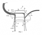
- Fig. 1 shows one embodiment of a flexible optical circuit having an integrated fiber breakout.
- the present invention relates to the integration of a fiber breakout into a flexible optical circuit. More specifically, Applicant recognizes that a discrete breakout adds significant complexity and size to the fiber circuit. Applicant further recognizes that the function of the breakout - i.e. fanning fibers from a ribbon cable - can be performed within the optical substrate itself. In other words, rather than having a discrete fiber breakout coupled to a ribbon fiber extending from the optical circuit, the fibers can be routed on the substrate such that they extend from the substrate as discrete fibers. Unlike the conventional approach, the conformal coating is no longer necessary to ribbonize the fibers extending from the substrate. However, Applicants recognize that individual fibers extending from the optical substrate will encounter strain along the perimeter of the optical substrate.
- Applicant discloses herein an approach for protecting the fibers either as a ribbon cable or as individual fibers as they extend past the perimeter of the flexible substrate. Therefore, the present invention provides for an optical flexible optical circuit that not only manages and secures fibers, but also integrates a fiber breakout to avoid the need for space-consuming discrete fiber breakouts as used in the prior art.
- one aspect of the present invention is an optical flexible optical circuit as defined in claim 1.
- Another aspect of the invention is a method of preparing the optical circuit with an integrated fiber breakout as defined in claim 13.
- Flexible optical circuit 100 comprises (a) a flexible substrate 101 defining a perimeter 101a; (b) an adhesive layer on at least a portion of the substrate; (c) a plurality of bare fibers 102 laid out on the adhesive layer, wherein each end of each fiber of the plurality of fibers extends from the perimeter to define a fiber extension 102a/102b; and a protective coating 103 around at least a portion of the fiber extension, the protective coating extending across the perimeter, thereby providing strain relief in the each fiber at the perimeter.
- the flexible substrate functions to provide a flexible support for the fibers.
- the optical substrate comprises features for facilitating mechanical connection to a structure such as a cable tray or panel.
- the substrate comprises orifices to receive fasteners. Still other mechanical connection features will be known to those of skill in the art in the light of this disclosure.
- the flexible substrate may comprise any known flexible substrate material including, for example, polyimide film (e.g., Kapton ® from DuPont), Polyester Films (e.g., Mylar ® Polyester Film), Metalized Polyester Film, PET Polyester Film, APET Polyethylene Teraphthalate Film, PETG Polyester Teraphthalate Glycol Film (e.g., Valox ® Polyester).
- An adhesive layer covers at least a portion of the flexible substrate.
- the function of the adhesive layer is to secure the optical fibers once they are routed on the substrate.
- substrates are commercially available with an adhesive layer already applied. Again, such adhesives are well known and will not be considered in detail herein. Suffice to say that typical adhesives are 300468 & 9375W 3M Adhesive.
- Optical fibers are routed on the adhesive layer.
- Fiber routing configurations on flexible optical circuits are well-known.
- the configuration might be a fiber shuffle in which a fiber for one group is split off and combined with fibers in a different group.
- the configuration might be a plurality of discrete fibers grouped together to form one or more ribbon cables.
- suitable optical fiber routing machines are available from TEGEMA (Netherlands).
- the routing machine lays fiber not only on the substrate, but also on a tacky film beyond the perimeter of the substrate.
- the tacky film is well known to those of skill in the art and functions to secure/manage the fiber extensions temporarily.
- an important feature of the claimed invention is that the breakout of the fibers occurs in the substrate and not in a discrete breakout component. This saves considerable space and simplifies fiber management. Accordingly, in one embodiment, at least a portion of the fibers extend individually from the substrate. For example, referring to Fig. 1 , optical fibers are routed on the substrate 101 such that a portion of the fiber extensions 102a extend as single fibers from groupings 130 and 131. Additionally, in this embodiment, a portion of fiber extensions 102b extend from the substrate as ribbon fiber or cable 104 as shown in groupings 132 and 133.
- the fibers may be routed and grouped as required by the application, meaning that the fiber extensions 102a and 102b may be discrete single fibers, groupings of single fibers, or multiple fibers configured as ribbon fibers. There is no limitation as to the type and number of fiber groupings. Additionally, it should be recognized that although Fig. 1 shows groupings of single fibers concentrated in groupings 130 and 131, other embodiments are possible. For example, rather than concentrating the single fibers in groups along the perimeter, they may be instead dispersed along the substrate's perimeter, which may be preferable in some applications to properly fan-out the fibers. Again, one of skill in the art will determine the optimum fiber routing configuration in the light of this disclosure.
- Another important feature of the claimed invention of the present invention is that for fiber extensions are protected by a protective covering 103/103a/103b.
- a protective covering 103/103a/103b By way of background, as mentioned above, in a conventional optical circuit, the extending fibers would be protected by a conformal coating used to ribbonize the fiber extensions.
- the fibers extending from the substrate are discrete fibers (i.e. not ribbonized), and thus are not suited for conformal coating.
- the fiber strain is likely to occur at the perimeter of the substrate because the fiber on the substrate is anchored to the substrate, while its extending end is free to move. Therefore, to overcome this potential strain, the fiber extensions 102a and/or 102b are covered by protective covering along the perimeter of the substrate.
- the protective covering may be any known covering for an optical fiber or cable assembly.
- an optical fiber or cable assembly for example, for a single fiber it may be any known flexible furcation tubing, such as, for example, PVC, and, for a grouping of fibers, it may be a heat-shrink polyolefin tubing as disclosed in US Application No. 16/249,810 .
- multiple fibers may be ribbonized using a conformal coating as discussed above.
- the method for applying the protective coating on the fibers may vary, and one embodiment, individual fibers are lifted from tacky film described above, and the furcation tubing slid over them. In multiple fiber groupings, a heat-shrink polyolefin tubing as maybe slid over the fibers as described in US Application No. 16/249,810 . These are simple, straightforward approaches for applying protective covering to the fibers. Those of skill in the art, in the light of this disclosure, are likely to develop alternative methods for disposing protective covering over the fibers.
- the protective covering extends inwardly from the perimeter of the substrate. Generally, a larger lap of protective covering across the perimeter of the substrate is preferred to reduce stress. Those of skill in the art can determine the extent of this lap-i.e. how far inward the protective covering needs to extend within the perimeter to provide sufficient strain relief. In one embodiment, the protective covering extends inwardly from the perimeter of the substrate at least 5 mm, and, in another embodiment, at least 7 mm, and, in another embodiment, at least 10 mm.
- the protective coating extends inward of the perimeter, but not to the point at which the fiber is curved. Accordingly, in one embodiment, the protective coating does not extend inward from the perimeter more than 25 mm, and, in another embodiment, more than 20 mm.
- opposing flexible substrates 110a, 110b are used.
- the substrate comprises opposed first and second substrates 110a, 110b configured to sandwich the adhesive layer and at least a portion of the plurality of fibers. More specifically, in one embodiment, once the fibers are routed on the substrate 110a and the protective coverings are disposed on the fiber extensions, a second substrate 110b, mirroring the first substrate, is applied over the top of the first substrate. This serves a number of functions. First, the second substrate provides additional strength and covers the fibers to prevent abrasion or other environmental assault of the fibers. Additionally, the second substrate covers the adhesive layer such that debris and other contaminants are not inadvertently glued to the substrate.
- a conformal coating can be applied over the adhesive layer and routed fibers providing that the single fiber extensions, or groupings of fiber extensions that are intended for a heat shrink protective coating, are masked from the conformal coating. It should be noted that, as mentioned below, it may be preferable to apply a conformal coating on multiple fibers which are intended to be ribbonized.
- the substrate(s) with the adhesive layer are heat-treated/baked to ruggedized the flexible optical circuit.
- the temperatures for heat treating will be obvious to those of skill in the art in the light of this disclosure. Suitable results have been obtained with heat treating in the range of 70 to 85° C.
- the fiber extensions are terminated either with a multi-fiber termini 152 in the case of a multifiber grouping, or with a single terminus 151 in the case of a discrete fiber.
- the termini may be any known configuration including traditional ferrules.
- single fiber ferrules may include, for example, LC or SC ferrules
- multifiber ferrules may include, for example, MT ferrules.
Landscapes
- Physics & Mathematics (AREA)
- General Physics & Mathematics (AREA)
- Optics & Photonics (AREA)
- Light Guides In General And Applications Therefor (AREA)
Description
- The present invention relates generally to a flexible optical circuit, and, more particular, to a flexible optical circuit integrated with a fiber breakout.
- The recent surge in demand for bandwidth is creating new challenges for designers of next generation optical networks and systems. In addition to a many-fold increase in the line rate of optical channels which now requires optical transmission, switching, cross-connection, etc., new multiplexing schemes are being implemented in order to efficiently transport, process and distribute information to end users. Thus back-planes, cross-connects and distributions panels become highly optical-connection-density intensive. This in turn results in a many-fold increase in the number of fiber optic jumpers and fan-out cables that are needed to interconnect the required optical connections in an orderly, manageable, predictable and cost-effective manner. This becomes a serious problem both in terms of space for dressing optical cables and cost for implementing and maintaining such systems. The situation is particularly problematic in applications in which space is at a premium, such as, for example, in aircraft applications. Therefore, new approaches must be developed to address optical fiber congestion problems.
- One approach for managing optical fibers is a flexible optical circuit. Such circuits are well known and are disclosed in
US 2004/0161212 andUS 6619853 . A conventional flexible optical circuit comprises a flexible substrate having an adhesive surface upon which optical fibers are routed and secured such that the fibers are organized and held in place to maintain a minimum bend radius. A length of each fiber extends from the substrate. A conformal coating is typically applied over the substrate, and over the extending fibers to form ribbon cables. Thus, a typical flexible optical circuit comprises a flexible substrate from which ribbon fibers extend. Based upon the application, these ribbon cables are either terminated with a multi-fiber termini, or they are broken down into individual fibers in fiber breakouts and then terminated with single or multifiber termini. These are well-known configurations. - The flexible optical circuit configuration has been successful in meeting many of the demands of high density fiber routing. However, Applicant has determined that the conventional flexible optical circuit configuration are particular problematic in applications in which space is limited- e.g. aircraft applications. Specifically, because of the lightweight and zero electromagnetic interference (EMI) associated with optical fibers, they are preferred for aircraft applications, especially in high-performance aircraft such as jet fighters and the like. However, as the use of optical fibers increases in these applications, optical fiber management becomes more of a problem. For instance, Applicant has determined that in many cases, there is simply not enough space for the optical circuits and their associated breakouts in the allotted cable trays. This results in installers forcing optical circuit and their breakouts into limited space often straining the optical circuits and/or the fibers which can lead to diminished optical quality or premature failure.
- Accordingly, Applicant identifies the need for a flexible optical circuit configuration having individual fiber breakouts with a minimal footprint. The present invention fulfills this need among others.
- The solution is provided by the integration of a fiber breakout into a flexible optical circuit as defined in claim 1. More specifically, Applicant recognizes that a discrete breakout adds significant complexity and size to the fiber circuit. Applicant further recognizes that the function of the breakout - i.e. fanning fibers from a ribbon cable - can be performed within the optical substrate itself. In other words, rather than having a discrete fiber breakout coupled to a ribbon fiber extending from the optical circuit, the fibers can be routed on the substrate such that they extend from the substrate as discrete fibers. Unlike the conventional approach, the conformal coating is no longer necessary to ribbonize the fibers extending from the substrate. However, Applicants recognize that individual fibers extending from the optical substrate will encounter strain along the perimeter of the optical substrate. Accordingly, Applicant discloses herein an approach for protecting the fibers either as a ribbon cable or as individual fibers as they extend past the perimeter of the flexible substrate. Therefore, the present invention provides for an optical flexible optical circuit that not only manages and secures fibers, but also integrates a fiber breakout to avoid the need for space-consuming discrete fiber breakouts as used in the prior art.
- The invention will now be described by way of example with reference to the accompanying drawings in which:
-
Fig. 1 shows one embodiment of a flexible optical circuit having an integrated fiber breakout. - The present invention relates to the integration of a fiber breakout into a flexible optical circuit. More specifically, Applicant recognizes that a discrete breakout adds significant complexity and size to the fiber circuit. Applicant further recognizes that the function of the breakout - i.e. fanning fibers from a ribbon cable - can be performed within the optical substrate itself. In other words, rather than having a discrete fiber breakout coupled to a ribbon fiber extending from the optical circuit, the fibers can be routed on the substrate such that they extend from the substrate as discrete fibers. Unlike the conventional approach, the conformal coating is no longer necessary to ribbonize the fibers extending from the substrate. However, Applicants recognize that individual fibers extending from the optical substrate will encounter strain along the perimeter of the optical substrate. Accordingly, Applicant discloses herein an approach for protecting the fibers either as a ribbon cable or as individual fibers as they extend past the perimeter of the flexible substrate. Therefore, the present invention provides for an optical flexible optical circuit that not only manages and secures fibers, but also integrates a fiber breakout to avoid the need for space-consuming discrete fiber breakouts as used in the prior art.
- Accordingly, one aspect of the present invention is an optical flexible optical circuit as defined in claim 1.
- Another aspect of the invention is a method of preparing the optical circuit with an integrated fiber breakout as defined in claim 13.
- Referring to
Fig. 1 , one embodiment of a flexibleoptical circuit 100 of the present invention is shown. Flexibleoptical circuit 100 comprises (a) aflexible substrate 101 defining aperimeter 101a; (b) an adhesive layer on at least a portion of the substrate; (c) a plurality ofbare fibers 102 laid out on the adhesive layer, wherein each end of each fiber of the plurality of fibers extends from the perimeter to define afiber extension 102a/102b; and a protective coating 103 around at least a portion of the fiber extension, the protective coating extending across the perimeter, thereby providing strain relief in the each fiber at the perimeter. - These features will be described are described below in greater detail and in connection with selected alternative embodiments.
- The flexible substrate functions to provide a flexible support for the fibers. In one embodiment, the optical substrate comprises features for facilitating mechanical connection to a structure such as a cable tray or panel. For example, in one embodiment, the substrate comprises orifices to receive fasteners. Still other mechanical connection features will be known to those of skill in the art in the light of this disclosure. The flexible substrate may comprise any known flexible substrate material including, for example, polyimide film (e.g., Kapton® from DuPont), Polyester Films (e.g., Mylar® Polyester Film), Metalized Polyester Film, PET Polyester Film, APET Polyethylene Teraphthalate Film, PETG Polyester Teraphthalate Glycol Film (e.g., Valox® Polyester).
- An adhesive layer covers at least a portion of the flexible substrate. The function of the adhesive layer is to secure the optical fibers once they are routed on the substrate. Often, substrates are commercially available with an adhesive layer already applied. Again, such adhesives are well known and will not be considered in detail herein. Suffice to say that typical adhesives are 300468 & 9375W 3M Adhesive.
- Optical fibers are routed on the adhesive layer. Fiber routing configurations on flexible optical circuits are well-known. For example, in one embodiment, the configuration might be a fiber shuffle in which a fiber for one group is split off and combined with fibers in a different group. In another embodiment, the configuration might be a plurality of discrete fibers grouped together to form one or more ribbon cables. The apparatus and techniques for doing this are well known. For example, suitable optical fiber routing machines are available from TEGEMA (Netherlands). In one embodiment, the routing machine lays fiber not only on the substrate, but also on a tacky film beyond the perimeter of the substrate. The tacky film is well known to those of skill in the art and functions to secure/manage the fiber extensions temporarily.
- As mentioned above, an important feature of the claimed invention is that the breakout of the fibers occurs in the substrate and not in a discrete breakout component. This saves considerable space and simplifies fiber management. Accordingly, in one embodiment, at least a portion of the fibers extend individually from the substrate. For example, referring to
Fig. 1 , optical fibers are routed on thesubstrate 101 such that a portion of thefiber extensions 102a extend as single fibers fromgroupings cable 104 as shown ingroupings - One of skill in the art will appreciate that the fibers may be routed and grouped as required by the application, meaning that the
fiber extensions 102a and 102b may be discrete single fibers, groupings of single fibers, or multiple fibers configured as ribbon fibers. There is no limitation as to the type and number of fiber groupings. Additionally, it should be recognized that althoughFig. 1 shows groupings of single fibers concentrated ingroupings - Another important feature of the claimed invention of the present invention is that for fiber extensions are protected by a protective covering 103/103a/103b. By way of background, as mentioned above, in a conventional optical circuit, the extending fibers would be protected by a conformal coating used to ribbonize the fiber extensions. However, as disclosed herein, at least a portion of the fibers extending from the substrate are discrete fibers (i.e. not ribbonized), and thus are not suited for conformal coating. However, Applicant appreciates that the fiber strain is likely to occur at the perimeter of the substrate because the fiber on the substrate is anchored to the substrate, while its extending end is free to move. Therefore, to overcome this potential strain, the
fiber extensions 102a and/or 102b are covered by protective covering along the perimeter of the substrate. - The protective covering may be any known covering for an optical fiber or cable assembly. For example, for a single fiber it may be any known flexible furcation tubing, such as, for example, PVC, and, for a grouping of fibers, it may be a heat-shrink polyolefin tubing as disclosed in
US Application No. 16/249,810 - Although the method for applying the protective coating on the fibers may vary, and one embodiment, individual fibers are lifted from tacky film described above, and the furcation tubing slid over them. In multiple fiber groupings, a heat-shrink polyolefin tubing as maybe slid over the fibers as described in
US Application No. 16/249,810 - Applicant has found that it is important for the protective covering to extend inwardly from the perimeter of the substrate. Generally, a larger lap of protective covering across the perimeter of the substrate is preferred to reduce stress. Those of skill in the art can determine the extent of this lap--i.e. how far inward the protective covering needs to extend within the perimeter to provide sufficient strain relief. In one embodiment, the protective covering extends inwardly from the perimeter of the substrate at least 5 mm, and, in another embodiment, at least 7 mm, and, in another embodiment, at least 10 mm.
- At some point, extending the protective coating inward of the perimeter of the substrate has diminished benefit as the substrate/adhesive provides adequate support and strain relief for the fiber. Again, those of skill the art can determine the point at which the protective coating is no longer improving strain relief. Additionally, at some point, the fiber needs to be routed, as described above, which involves bending the fiber. Such routing may be impeded by the protective coating. Thus, in a preferred embodiment, the protective coating extends inward of the perimeter, but not to the point at which the fiber is curved. Accordingly, in one embodiment, the protective coating does not extend inward from the perimeter more than 25 mm, and, in another embodiment, more than 20 mm.
- According to the claimed invention, opposing
flexible substrates second substrates substrate 110a and the protective coverings are disposed on the fiber extensions, asecond substrate 110b, mirroring the first substrate, is applied over the top of the first substrate. This serves a number of functions. First, the second substrate provides additional strength and covers the fibers to prevent abrasion or other environmental assault of the fibers. Additionally, the second substrate covers the adhesive layer such that debris and other contaminants are not inadvertently glued to the substrate. - Alternatively, rather than, or in addition to, a second substrate as described herein, a conformal coating can be applied over the adhesive layer and routed fibers providing that the single fiber extensions, or groupings of fiber extensions that are intended for a heat shrink protective coating, are masked from the conformal coating. It should be noted that, as mentioned below, it may be preferable to apply a conformal coating on multiple fibers which are intended to be ribbonized.
- In one embodiment, the substrate(s) with the adhesive layer are heat-treated/baked to ruggedized the flexible optical circuit. The temperatures for heat treating will be obvious to those of skill in the art in the light of this disclosure. Suitable results have been obtained with heat treating in the range of 70 to 85° C.
- In one embodiment, the fiber extensions are terminated either with a
multi-fiber termini 152 in the case of a multifiber grouping, or with asingle terminus 151 in the case of a discrete fiber. The termini may be any known configuration including traditional ferrules. For example, single fiber ferrules may include, for example, LC or SC ferrules, and, multifiber ferrules may include, for example, MT ferrules.
Claims (15)
- A flexible optical circuit (100) comprising:a flexible substrate (101) defining a perimeter (101a);an adhesive layer on at least a portion of said substrate (101); anda plurality of fibers (102) laid out on said adhesive layer, wherein each end of each fiber (102) of said plurality of fibers (102) extends from said perimeter (101a) to define a plurality of fiber extensions (102a, 102b) wherein at least a portion of said fiber extensions are discrete, single-fiber extension (102a);characterised in that the substrate (101) comprises opposed first and second substrates (110a, 110b) configured to sandwich said adhesive layer and at least a portion of said plurality of fibers (102) and the optical circuit (100) further comprises a protective coating (103, 103a) around at least a portion of each of said discrete single-fiber extensions (102a) said protective coatings (103, 103a) extending inwardly from said perimeter (101a) and configured to provide strain relief for said each of said discrete single-fiber extensions (102a).
- The flexible optical circuit (100) of claim 1, wherein said protective coating (103, 103a) extends at least 3 mm inward of said perimeter (101a).
- The flexible optical circuit (100) of claim 2, wherein said protective coating (103, 103a) extends at least 5 mm inward of said perimeter (101a).
- The flexible optical circuit (100) of any preceding claim, wherein said protective coating (103, 103a) extends no more than 25 mm inward of said perimeter (101a).
- The flexible optical circuit (100) of claim 4, wherein said protective coating (103, 103a) extends no more than 20 mm inward of said perimeter (101a).
- The flexible optical circuit (100) of any preceding claim, wherein, for a single fiber, the protective coating is a flexible furcation tubing.
- The flexible optical circuit (100) of any preceding claim, wherein, for a grouping of fibers, the protective coating is a heat-shrink material.
- The flexible optical circuit (100) of any of claims 1 to 7, further comprising a conformal coating covering said adhesive layer and at least a portion of said plurality of fibers (102).
- The flexible optical circuit (100) of any preceding claim, wherein said fiber extensions (102a, 102b) define at least first and second groupings, said first grouping (130, 131) comprises discrete said fiber extensions (102a), and said second grouping (132 133) comprises multiple said fiber extensions (102b).
- The flexible optical circuit (100) of claim 9, wherein said second grouping (132, 133) is combined to define a ribbon cable (104).
- The flexible optical circuit (100) of claim 10, wherein said second grouping (132, 133) is ribbonized
- The flexible optical circuit (100) of claim 10 or 11, wherein said ribbon cable (104) is terminated with a termini (152).
- A method of making a flexible optical circuit (100) comprising:routing a plurality of fibers (102) on an adhesive layer overlaying at least a portion of a flexible substrate (101, 110a) defining a perimeter (101a), wherein each end of each fiber (102) of said plurality of fibers (102) extends from said perimeter (101a) to define a plurality of fiber extensions (102a, 102b), wherein at least a portion of said fiber extensions are discrete, single-fiber extensions (102a);disposing a protective coating (103, 103a, 103b) around at least a portion of each of said fiber extension (102a, 102b), said protective coatings (103, 103a, 103b) extending inwardly from said perimeter (101a) to provide strain relief for said each of said fiber extension (102a, 102b); andapplying a second substrate (110b) over at least a portion of said plurality of fibers (102) such that said at least a portion of said plurality of fibers (102) is sandwiched between said substrate (110a) and said second substrate (110b).
- The method of claim 14, wherein said protective coating (103, 103a, 103b) extends at least 3 mm inward of said perimeter (101a).
- The method of claim 13 or 14, wherein said protective coating (103, 103a 103b) extends no more than 25 mm inward of said perimeter (101a).
Applications Claiming Priority (1)
| Application Number | Priority Date | Filing Date | Title |
|---|---|---|---|
| US16/562,023 US11169331B2 (en) | 2019-09-05 | 2019-09-05 | Flexible optical circuit with integrated fiber breakout |
Publications (2)
| Publication Number | Publication Date |
|---|---|
| EP3789801A1 EP3789801A1 (en) | 2021-03-10 |
| EP3789801B1 true EP3789801B1 (en) | 2024-07-31 |
Family
ID=72380945
Family Applications (1)
| Application Number | Title | Priority Date | Filing Date |
|---|---|---|---|
| EP20194522.7A Active EP3789801B1 (en) | 2019-09-05 | 2020-09-04 | Flexible optical circuit with integrated fiber breakout |
Country Status (2)
| Country | Link |
|---|---|
| US (1) | US11169331B2 (en) |
| EP (1) | EP3789801B1 (en) |
Families Citing this family (7)
| Publication number | Priority date | Publication date | Assignee | Title |
|---|---|---|---|---|
| US9417418B2 (en) | 2011-09-12 | 2016-08-16 | Commscope Technologies Llc | Flexible lensed optical interconnect device for signal distribution |
| US9488788B2 (en) | 2012-09-28 | 2016-11-08 | Commscope Technologies Llc | Fiber optic cassette |
| EP2901191A4 (en) | 2012-09-28 | 2016-10-26 | Tyco Electronics Ltd Uk | MANUFACTURING AND TESTING OF CASSETTE FOR OPTICAL FIBER |
| US9223094B2 (en) | 2012-10-05 | 2015-12-29 | Tyco Electronics Nederland Bv | Flexible optical circuit, cassettes, and methods |
| MX2020002878A (en) | 2017-10-02 | 2020-07-22 | Commscope Technologies Llc | Fiber optic circuit and preparation method. |
| US12339511B2 (en) | 2020-03-31 | 2025-06-24 | Commscope Technologies Llc | Fiber optic cable management systems and methods |
| US11927823B2 (en) | 2021-02-26 | 2024-03-12 | Te Connectivity Solutions Gmbh | Cable assembly |
Family Cites Families (10)
| Publication number | Priority date | Publication date | Assignee | Title |
|---|---|---|---|---|
| US6522817B2 (en) * | 2000-12-18 | 2003-02-18 | Veritech, Inc. | Optical fiber array and method of formation |
| JP3883387B2 (en) | 2001-01-09 | 2007-02-21 | 日本電信電話株式会社 | Method of forming and processing connection end face of optical fiber |
| US6619853B2 (en) | 2001-03-14 | 2003-09-16 | Molex Incorporated | Optical fiber interconnection system |
| US6614971B2 (en) | 2001-12-04 | 2003-09-02 | Molex Incorporated | Fanout system or apparatus for a fiber optic cable and including a method of fabricating same |
| US20040161212A1 (en) | 2003-02-18 | 2004-08-19 | Sun Maurice X. | Fiber optic apparatus |
| JP2007147982A (en) * | 2005-11-28 | 2007-06-14 | Seikoh Giken Co Ltd | Optical fiber array and manufacturing method thereof |
| EP2901191A4 (en) | 2012-09-28 | 2016-10-26 | Tyco Electronics Ltd Uk | MANUFACTURING AND TESTING OF CASSETTE FOR OPTICAL FIBER |
| WO2015161204A1 (en) * | 2014-04-17 | 2015-10-22 | Molex Incorporated | Multi-layer flexible optical circuit |
| CN108603990B (en) | 2016-01-12 | 2021-05-28 | 康普连通比利时私人有限公司 | Cable management arrangement |
| US10107967B1 (en) | 2017-10-30 | 2018-10-23 | Corning Research & Development Corporation | Fiber array assemblies for multifiber connectorized ribbon cables and methods of forming same |
-
2019
- 2019-09-05 US US16/562,023 patent/US11169331B2/en active Active
-
2020
- 2020-09-04 EP EP20194522.7A patent/EP3789801B1/en active Active
Also Published As
| Publication number | Publication date |
|---|---|
| US11169331B2 (en) | 2021-11-09 |
| US20210072463A1 (en) | 2021-03-11 |
| EP3789801A1 (en) | 2021-03-10 |
Similar Documents
| Publication | Publication Date | Title |
|---|---|---|
| US11169331B2 (en) | Flexible optical circuit with integrated fiber breakout | |
| EP0889344B1 (en) | Fiber optic ribbon interconnect cable | |
| EP1436650B1 (en) | Use of an apparatus of cross-connecting optical fibres | |
| EP1312961B1 (en) | Device including a fiber optic cable harness and associated methods | |
| US12585067B2 (en) | Cable management arrangement | |
| US6498882B1 (en) | Assembly and method for reorganizing planar lightwave circuit channels | |
| EP3504572B1 (en) | System comprising a light weight fiber optic splice | |
| CA2987357C (en) | Optical fiber cord and method of manufacturing optical fiber cord | |
| EP0953857A1 (en) | Optical Fiber | |
| US11249269B2 (en) | Multi-level optical cassette | |
| JP3972203B2 (en) | Optical wiring component and method for manufacturing optical wiring component | |
| US9971093B2 (en) | Optical fiber splitter modules | |
| US20040114902A1 (en) | Apparatus and method for creating a fiber optic circuit | |
| EP1182484B1 (en) | Optical fiber separation and regrouping device | |
| US20020197033A1 (en) | Separable optical fiber ribbon having a tape with a preferential splitting direction and associated methods of fabricating and splitting the optical fiber ribbon | |
| EP4050391A1 (en) | Cable assembly | |
| US20070003190A1 (en) | Optical planar splitter | |
| EP4231075A1 (en) | Fanout tube for a furcation of a fiber optic cable and related method | |
| US20070140639A1 (en) | Methods for making fiber optic cables having at least one tether optical fiber | |
| CN117561465A (en) | Optical modules including striped optical fiber and optical fiber cabling equipment | |
| WO2025165704A1 (en) | Fiber optic management and identification systems and methods | |
| Shahid et al. | Flexible High density optical circuits | |
| JP2001133639A (en) | Optical fiber wiring sheet |
Legal Events
| Date | Code | Title | Description |
|---|---|---|---|
| PUAI | Public reference made under article 153(3) epc to a published international application that has entered the european phase |
Free format text: ORIGINAL CODE: 0009012 |
|
| STAA | Information on the status of an ep patent application or granted ep patent |
Free format text: STATUS: THE APPLICATION HAS BEEN PUBLISHED |
|
| AK | Designated contracting states |
Kind code of ref document: A1 Designated state(s): AL AT BE BG CH CY CZ DE DK EE ES FI FR GB GR HR HU IE IS IT LI LT LU LV MC MK MT NL NO PL PT RO RS SE SI SK SM TR |
|
| AX | Request for extension of the european patent |
Extension state: BA ME |
|
| STAA | Information on the status of an ep patent application or granted ep patent |
Free format text: STATUS: REQUEST FOR EXAMINATION WAS MADE |
|
| 17P | Request for examination filed |
Effective date: 20210901 |
|
| RBV | Designated contracting states (corrected) |
Designated state(s): AL AT BE BG CH CY CZ DE DK EE ES FI FR GB GR HR HU IE IS IT LI LT LU LV MC MK MT NL NO PL PT RO RS SE SI SK SM TR |
|
| STAA | Information on the status of an ep patent application or granted ep patent |
Free format text: STATUS: EXAMINATION IS IN PROGRESS |
|
| 17Q | First examination report despatched |
Effective date: 20230404 |
|
| RAP1 | Party data changed (applicant data changed or rights of an application transferred) |
Owner name: TE CONNECTIVITY SOLUTIONS GMBH |
|
| GRAP | Despatch of communication of intention to grant a patent |
Free format text: ORIGINAL CODE: EPIDOSNIGR1 |
|
| STAA | Information on the status of an ep patent application or granted ep patent |
Free format text: STATUS: GRANT OF PATENT IS INTENDED |
|
| INTG | Intention to grant announced |
Effective date: 20240402 |
|
| GRAS | Grant fee paid |
Free format text: ORIGINAL CODE: EPIDOSNIGR3 |
|
| GRAA | (expected) grant |
Free format text: ORIGINAL CODE: 0009210 |
|
| STAA | Information on the status of an ep patent application or granted ep patent |
Free format text: STATUS: THE PATENT HAS BEEN GRANTED |
|
| AK | Designated contracting states |
Kind code of ref document: B1 Designated state(s): AL AT BE BG CH CY CZ DE DK EE ES FI FR GB GR HR HU IE IS IT LI LT LU LV MC MK MT NL NO PL PT RO RS SE SI SK SM TR |
|
| REG | Reference to a national code |
Ref country code: CH Ref legal event code: EP Ref country code: GB Ref legal event code: FG4D |
|
| REG | Reference to a national code |
Ref country code: DE Ref legal event code: R096 Ref document number: 602020034759 Country of ref document: DE |
|
| REG | Reference to a national code |
Ref country code: IE Ref legal event code: FG4D |
|
| REG | Reference to a national code |
Ref country code: LT Ref legal event code: MG9D |
|
| REG | Reference to a national code |
Ref country code: NL Ref legal event code: MP Effective date: 20240731 |
|
| PG25 | Lapsed in a contracting state [announced via postgrant information from national office to epo] |
Ref country code: PT Free format text: LAPSE BECAUSE OF FAILURE TO SUBMIT A TRANSLATION OF THE DESCRIPTION OR TO PAY THE FEE WITHIN THE PRESCRIBED TIME-LIMIT Effective date: 20241202 |
|
| REG | Reference to a national code |
Ref country code: AT Ref legal event code: MK05 Ref document number: 1709007 Country of ref document: AT Kind code of ref document: T Effective date: 20240731 |
|
| PG25 | Lapsed in a contracting state [announced via postgrant information from national office to epo] |
Ref country code: PT Free format text: LAPSE BECAUSE OF FAILURE TO SUBMIT A TRANSLATION OF THE DESCRIPTION OR TO PAY THE FEE WITHIN THE PRESCRIBED TIME-LIMIT Effective date: 20241202 |
|
| PG25 | Lapsed in a contracting state [announced via postgrant information from national office to epo] |
Ref country code: NO Free format text: LAPSE BECAUSE OF FAILURE TO SUBMIT A TRANSLATION OF THE DESCRIPTION OR TO PAY THE FEE WITHIN THE PRESCRIBED TIME-LIMIT Effective date: 20241031 |
|
| PG25 | Lapsed in a contracting state [announced via postgrant information from national office to epo] |
Ref country code: NL Free format text: LAPSE BECAUSE OF FAILURE TO SUBMIT A TRANSLATION OF THE DESCRIPTION OR TO PAY THE FEE WITHIN THE PRESCRIBED TIME-LIMIT Effective date: 20240731 Ref country code: FI Free format text: LAPSE BECAUSE OF FAILURE TO SUBMIT A TRANSLATION OF THE DESCRIPTION OR TO PAY THE FEE WITHIN THE PRESCRIBED TIME-LIMIT Effective date: 20240731 Ref country code: PL Free format text: LAPSE BECAUSE OF FAILURE TO SUBMIT A TRANSLATION OF THE DESCRIPTION OR TO PAY THE FEE WITHIN THE PRESCRIBED TIME-LIMIT Effective date: 20240731 Ref country code: GR Free format text: LAPSE BECAUSE OF FAILURE TO SUBMIT A TRANSLATION OF THE DESCRIPTION OR TO PAY THE FEE WITHIN THE PRESCRIBED TIME-LIMIT Effective date: 20241101 |
|
| PG25 | Lapsed in a contracting state [announced via postgrant information from national office to epo] |
Ref country code: BG Free format text: LAPSE BECAUSE OF FAILURE TO SUBMIT A TRANSLATION OF THE DESCRIPTION OR TO PAY THE FEE WITHIN THE PRESCRIBED TIME-LIMIT Effective date: 20240731 |
|
| PG25 | Lapsed in a contracting state [announced via postgrant information from national office to epo] |
Ref country code: LV Free format text: LAPSE BECAUSE OF FAILURE TO SUBMIT A TRANSLATION OF THE DESCRIPTION OR TO PAY THE FEE WITHIN THE PRESCRIBED TIME-LIMIT Effective date: 20240731 |
|
| PG25 | Lapsed in a contracting state [announced via postgrant information from national office to epo] |
Ref country code: AT Free format text: LAPSE BECAUSE OF FAILURE TO SUBMIT A TRANSLATION OF THE DESCRIPTION OR TO PAY THE FEE WITHIN THE PRESCRIBED TIME-LIMIT Effective date: 20240731 Ref country code: IS Free format text: LAPSE BECAUSE OF FAILURE TO SUBMIT A TRANSLATION OF THE DESCRIPTION OR TO PAY THE FEE WITHIN THE PRESCRIBED TIME-LIMIT Effective date: 20241130 |
|
| PG25 | Lapsed in a contracting state [announced via postgrant information from national office to epo] |
Ref country code: HR Free format text: LAPSE BECAUSE OF FAILURE TO SUBMIT A TRANSLATION OF THE DESCRIPTION OR TO PAY THE FEE WITHIN THE PRESCRIBED TIME-LIMIT Effective date: 20240731 |
|
| PG25 | Lapsed in a contracting state [announced via postgrant information from national office to epo] |
Ref country code: ES Free format text: LAPSE BECAUSE OF FAILURE TO SUBMIT A TRANSLATION OF THE DESCRIPTION OR TO PAY THE FEE WITHIN THE PRESCRIBED TIME-LIMIT Effective date: 20240731 Ref country code: RS Free format text: LAPSE BECAUSE OF FAILURE TO SUBMIT A TRANSLATION OF THE DESCRIPTION OR TO PAY THE FEE WITHIN THE PRESCRIBED TIME-LIMIT Effective date: 20241031 |
|
| PG25 | Lapsed in a contracting state [announced via postgrant information from national office to epo] |
Ref country code: RS Free format text: LAPSE BECAUSE OF FAILURE TO SUBMIT A TRANSLATION OF THE DESCRIPTION OR TO PAY THE FEE WITHIN THE PRESCRIBED TIME-LIMIT Effective date: 20241031 Ref country code: PL Free format text: LAPSE BECAUSE OF FAILURE TO SUBMIT A TRANSLATION OF THE DESCRIPTION OR TO PAY THE FEE WITHIN THE PRESCRIBED TIME-LIMIT Effective date: 20240731 Ref country code: NO Free format text: LAPSE BECAUSE OF FAILURE TO SUBMIT A TRANSLATION OF THE DESCRIPTION OR TO PAY THE FEE WITHIN THE PRESCRIBED TIME-LIMIT Effective date: 20241031 Ref country code: NL Free format text: LAPSE BECAUSE OF FAILURE TO SUBMIT A TRANSLATION OF THE DESCRIPTION OR TO PAY THE FEE WITHIN THE PRESCRIBED TIME-LIMIT Effective date: 20240731 Ref country code: LV Free format text: LAPSE BECAUSE OF FAILURE TO SUBMIT A TRANSLATION OF THE DESCRIPTION OR TO PAY THE FEE WITHIN THE PRESCRIBED TIME-LIMIT Effective date: 20240731 Ref country code: IS Free format text: LAPSE BECAUSE OF FAILURE TO SUBMIT A TRANSLATION OF THE DESCRIPTION OR TO PAY THE FEE WITHIN THE PRESCRIBED TIME-LIMIT Effective date: 20241130 Ref country code: HR Free format text: LAPSE BECAUSE OF FAILURE TO SUBMIT A TRANSLATION OF THE DESCRIPTION OR TO PAY THE FEE WITHIN THE PRESCRIBED TIME-LIMIT Effective date: 20240731 Ref country code: GR Free format text: LAPSE BECAUSE OF FAILURE TO SUBMIT A TRANSLATION OF THE DESCRIPTION OR TO PAY THE FEE WITHIN THE PRESCRIBED TIME-LIMIT Effective date: 20241101 Ref country code: FI Free format text: LAPSE BECAUSE OF FAILURE TO SUBMIT A TRANSLATION OF THE DESCRIPTION OR TO PAY THE FEE WITHIN THE PRESCRIBED TIME-LIMIT Effective date: 20240731 Ref country code: ES Free format text: LAPSE BECAUSE OF FAILURE TO SUBMIT A TRANSLATION OF THE DESCRIPTION OR TO PAY THE FEE WITHIN THE PRESCRIBED TIME-LIMIT Effective date: 20240731 Ref country code: BG Free format text: LAPSE BECAUSE OF FAILURE TO SUBMIT A TRANSLATION OF THE DESCRIPTION OR TO PAY THE FEE WITHIN THE PRESCRIBED TIME-LIMIT Effective date: 20240731 Ref country code: AT Free format text: LAPSE BECAUSE OF FAILURE TO SUBMIT A TRANSLATION OF THE DESCRIPTION OR TO PAY THE FEE WITHIN THE PRESCRIBED TIME-LIMIT Effective date: 20240731 |
|
| PG25 | Lapsed in a contracting state [announced via postgrant information from national office to epo] |
Ref country code: DK Free format text: LAPSE BECAUSE OF FAILURE TO SUBMIT A TRANSLATION OF THE DESCRIPTION OR TO PAY THE FEE WITHIN THE PRESCRIBED TIME-LIMIT Effective date: 20240731 Ref country code: RO Free format text: LAPSE BECAUSE OF FAILURE TO SUBMIT A TRANSLATION OF THE DESCRIPTION OR TO PAY THE FEE WITHIN THE PRESCRIBED TIME-LIMIT Effective date: 20240731 Ref country code: SM Free format text: LAPSE BECAUSE OF FAILURE TO SUBMIT A TRANSLATION OF THE DESCRIPTION OR TO PAY THE FEE WITHIN THE PRESCRIBED TIME-LIMIT Effective date: 20240731 |
|
| PG25 | Lapsed in a contracting state [announced via postgrant information from national office to epo] |
Ref country code: MC Free format text: LAPSE BECAUSE OF FAILURE TO SUBMIT A TRANSLATION OF THE DESCRIPTION OR TO PAY THE FEE WITHIN THE PRESCRIBED TIME-LIMIT Effective date: 20240731 Ref country code: EE Free format text: LAPSE BECAUSE OF FAILURE TO SUBMIT A TRANSLATION OF THE DESCRIPTION OR TO PAY THE FEE WITHIN THE PRESCRIBED TIME-LIMIT Effective date: 20240731 |
|
| PG25 | Lapsed in a contracting state [announced via postgrant information from national office to epo] |
Ref country code: CZ Free format text: LAPSE BECAUSE OF FAILURE TO SUBMIT A TRANSLATION OF THE DESCRIPTION OR TO PAY THE FEE WITHIN THE PRESCRIBED TIME-LIMIT Effective date: 20240731 |
|
| PG25 | Lapsed in a contracting state [announced via postgrant information from national office to epo] |
Ref country code: SK Free format text: LAPSE BECAUSE OF FAILURE TO SUBMIT A TRANSLATION OF THE DESCRIPTION OR TO PAY THE FEE WITHIN THE PRESCRIBED TIME-LIMIT Effective date: 20240731 Ref country code: IT Free format text: LAPSE BECAUSE OF FAILURE TO SUBMIT A TRANSLATION OF THE DESCRIPTION OR TO PAY THE FEE WITHIN THE PRESCRIBED TIME-LIMIT Effective date: 20240731 |
|
| REG | Reference to a national code |
Ref country code: CH Ref legal event code: PL |
|
| REG | Reference to a national code |
Ref country code: DE Ref legal event code: R097 Ref document number: 602020034759 Country of ref document: DE |
|
| PG25 | Lapsed in a contracting state [announced via postgrant information from national office to epo] |
Ref country code: LU Free format text: LAPSE BECAUSE OF NON-PAYMENT OF DUE FEES Effective date: 20240904 |
|
| PLBE | No opposition filed within time limit |
Free format text: ORIGINAL CODE: 0009261 |
|
| STAA | Information on the status of an ep patent application or granted ep patent |
Free format text: STATUS: NO OPPOSITION FILED WITHIN TIME LIMIT |
|
| 26N | No opposition filed |
Effective date: 20250501 |
|
| REG | Reference to a national code |
Ref country code: BE Ref legal event code: MM Effective date: 20240930 |
|
| PG25 | Lapsed in a contracting state [announced via postgrant information from national office to epo] |
Ref country code: BE Free format text: LAPSE BECAUSE OF NON-PAYMENT OF DUE FEES Effective date: 20240930 |
|
| PG25 | Lapsed in a contracting state [announced via postgrant information from national office to epo] |
Ref country code: CH Free format text: LAPSE BECAUSE OF NON-PAYMENT OF DUE FEES Effective date: 20240930 |
|
| PG25 | Lapsed in a contracting state [announced via postgrant information from national office to epo] |
Ref country code: IE Free format text: LAPSE BECAUSE OF NON-PAYMENT OF DUE FEES Effective date: 20240904 |
|
| PG25 | Lapsed in a contracting state [announced via postgrant information from national office to epo] |
Ref country code: SE Free format text: LAPSE BECAUSE OF FAILURE TO SUBMIT A TRANSLATION OF THE DESCRIPTION OR TO PAY THE FEE WITHIN THE PRESCRIBED TIME-LIMIT Effective date: 20240731 |
|
| PGFP | Annual fee paid to national office [announced via postgrant information from national office to epo] |
Ref country code: DE Payment date: 20250702 Year of fee payment: 6 |
|
| PGFP | Annual fee paid to national office [announced via postgrant information from national office to epo] |
Ref country code: GB Payment date: 20250703 Year of fee payment: 6 |
|
| PGFP | Annual fee paid to national office [announced via postgrant information from national office to epo] |
Ref country code: FR Payment date: 20250703 Year of fee payment: 6 |
|
| PG25 | Lapsed in a contracting state [announced via postgrant information from national office to epo] |
Ref country code: CY Free format text: LAPSE BECAUSE OF FAILURE TO SUBMIT A TRANSLATION OF THE DESCRIPTION OR TO PAY THE FEE WITHIN THE PRESCRIBED TIME-LIMIT; INVALID AB INITIO Effective date: 20200904 |
|
| PG25 | Lapsed in a contracting state [announced via postgrant information from national office to epo] |
Ref country code: HU Free format text: LAPSE BECAUSE OF FAILURE TO SUBMIT A TRANSLATION OF THE DESCRIPTION OR TO PAY THE FEE WITHIN THE PRESCRIBED TIME-LIMIT; INVALID AB INITIO Effective date: 20200904 |