EP3789791A1 - Impulse radar using variable pulse repetition frequency - Google Patents
Impulse radar using variable pulse repetition frequency Download PDFInfo
- Publication number
- EP3789791A1 EP3789791A1 EP20190352.3A EP20190352A EP3789791A1 EP 3789791 A1 EP3789791 A1 EP 3789791A1 EP 20190352 A EP20190352 A EP 20190352A EP 3789791 A1 EP3789791 A1 EP 3789791A1
- Authority
- EP
- European Patent Office
- Prior art keywords
- duration
- target
- transmitter
- gated mode
- mode
- Prior art date
- Legal status (The legal status is an assumption and is not a legal conclusion. Google has not performed a legal analysis and makes no representation as to the accuracy of the status listed.)
- Granted
Links
Images




Classifications
-
- G—PHYSICS
- G01—MEASURING; TESTING
- G01S—RADIO DIRECTION-FINDING; RADIO NAVIGATION; DETERMINING DISTANCE OR VELOCITY BY USE OF RADIO WAVES; LOCATING OR PRESENCE-DETECTING BY USE OF THE REFLECTION OR RERADIATION OF RADIO WAVES; ANALOGOUS ARRANGEMENTS USING OTHER WAVES
- G01S13/00—Systems using the reflection or reradiation of radio waves, e.g. radar systems; Analogous systems using reflection or reradiation of waves whose nature or wavelength is irrelevant or unspecified
- G01S13/88—Radar or analogous systems specially adapted for specific applications
- G01S13/93—Radar or analogous systems specially adapted for specific applications for anti-collision purposes
- G01S13/931—Radar or analogous systems specially adapted for specific applications for anti-collision purposes of land vehicles
-
- G—PHYSICS
- G01—MEASURING; TESTING
- G01S—RADIO DIRECTION-FINDING; RADIO NAVIGATION; DETERMINING DISTANCE OR VELOCITY BY USE OF RADIO WAVES; LOCATING OR PRESENCE-DETECTING BY USE OF THE REFLECTION OR RERADIATION OF RADIO WAVES; ANALOGOUS ARRANGEMENTS USING OTHER WAVES
- G01S13/00—Systems using the reflection or reradiation of radio waves, e.g. radar systems; Analogous systems using reflection or reradiation of waves whose nature or wavelength is irrelevant or unspecified
- G01S13/74—Systems using reradiation of radio waves, e.g. secondary radar systems; Analogous systems
- G01S13/76—Systems using reradiation of radio waves, e.g. secondary radar systems; Analogous systems wherein pulse-type signals are transmitted
-
- G—PHYSICS
- G01—MEASURING; TESTING
- G01S—RADIO DIRECTION-FINDING; RADIO NAVIGATION; DETERMINING DISTANCE OR VELOCITY BY USE OF RADIO WAVES; LOCATING OR PRESENCE-DETECTING BY USE OF THE REFLECTION OR RERADIATION OF RADIO WAVES; ANALOGOUS ARRANGEMENTS USING OTHER WAVES
- G01S13/00—Systems using the reflection or reradiation of radio waves, e.g. radar systems; Analogous systems using reflection or reradiation of waves whose nature or wavelength is irrelevant or unspecified
- G01S13/02—Systems using reflection of radio waves, e.g. primary radar systems; Analogous systems
- G01S13/06—Systems determining position data of a target
- G01S13/08—Systems for measuring distance only
- G01S13/10—Systems for measuring distance only using transmission of interrupted, pulse modulated waves
- G01S13/14—Systems for measuring distance only using transmission of interrupted, pulse modulated waves wherein a voltage or current pulse is initiated and terminated in accordance respectively with the pulse transmission and echo reception
- G01S13/16—Systems for measuring distance only using transmission of interrupted, pulse modulated waves wherein a voltage or current pulse is initiated and terminated in accordance respectively with the pulse transmission and echo reception using counters
-
- G—PHYSICS
- G01—MEASURING; TESTING
- G01S—RADIO DIRECTION-FINDING; RADIO NAVIGATION; DETERMINING DISTANCE OR VELOCITY BY USE OF RADIO WAVES; LOCATING OR PRESENCE-DETECTING BY USE OF THE REFLECTION OR RERADIATION OF RADIO WAVES; ANALOGOUS ARRANGEMENTS USING OTHER WAVES
- G01S13/00—Systems using the reflection or reradiation of radio waves, e.g. radar systems; Analogous systems using reflection or reradiation of waves whose nature or wavelength is irrelevant or unspecified
- G01S13/02—Systems using reflection of radio waves, e.g. primary radar systems; Analogous systems
- G01S13/06—Systems determining position data of a target
- G01S13/08—Systems for measuring distance only
- G01S13/10—Systems for measuring distance only using transmission of interrupted, pulse modulated waves
- G01S13/12—Systems for measuring distance only using transmission of interrupted, pulse modulated waves wherein the pulse-recurrence frequency is varied to provide a desired time relationship between the transmission of a pulse and the receipt of the echo of a preceding pulse
-
- G—PHYSICS
- G01—MEASURING; TESTING
- G01S—RADIO DIRECTION-FINDING; RADIO NAVIGATION; DETERMINING DISTANCE OR VELOCITY BY USE OF RADIO WAVES; LOCATING OR PRESENCE-DETECTING BY USE OF THE REFLECTION OR RERADIATION OF RADIO WAVES; ANALOGOUS ARRANGEMENTS USING OTHER WAVES
- G01S7/00—Details of systems according to groups G01S13/00, G01S15/00, G01S17/00
- G01S7/02—Details of systems according to groups G01S13/00, G01S15/00, G01S17/00 of systems according to group G01S13/00
- G01S7/03—Details of HF subsystems specially adapted therefor, e.g. common to transmitter and receiver
-
- G—PHYSICS
- G01—MEASURING; TESTING
- G01S—RADIO DIRECTION-FINDING; RADIO NAVIGATION; DETERMINING DISTANCE OR VELOCITY BY USE OF RADIO WAVES; LOCATING OR PRESENCE-DETECTING BY USE OF THE REFLECTION OR RERADIATION OF RADIO WAVES; ANALOGOUS ARRANGEMENTS USING OTHER WAVES
- G01S7/00—Details of systems according to groups G01S13/00, G01S15/00, G01S17/00
- G01S7/02—Details of systems according to groups G01S13/00, G01S15/00, G01S17/00 of systems according to group G01S13/00
- G01S7/28—Details of pulse systems
- G01S7/282—Transmitters
-
- G—PHYSICS
- G01—MEASURING; TESTING
- G01S—RADIO DIRECTION-FINDING; RADIO NAVIGATION; DETERMINING DISTANCE OR VELOCITY BY USE OF RADIO WAVES; LOCATING OR PRESENCE-DETECTING BY USE OF THE REFLECTION OR RERADIATION OF RADIO WAVES; ANALOGOUS ARRANGEMENTS USING OTHER WAVES
- G01S7/00—Details of systems according to groups G01S13/00, G01S15/00, G01S17/00
- G01S7/02—Details of systems according to groups G01S13/00, G01S15/00, G01S17/00 of systems according to group G01S13/00
- G01S7/28—Details of pulse systems
- G01S7/285—Receivers
- G01S7/292—Extracting wanted echo-signals
-
- G—PHYSICS
- G01—MEASURING; TESTING
- G01S—RADIO DIRECTION-FINDING; RADIO NAVIGATION; DETERMINING DISTANCE OR VELOCITY BY USE OF RADIO WAVES; LOCATING OR PRESENCE-DETECTING BY USE OF THE REFLECTION OR RERADIATION OF RADIO WAVES; ANALOGOUS ARRANGEMENTS USING OTHER WAVES
- G01S7/00—Details of systems according to groups G01S13/00, G01S15/00, G01S17/00
- G01S7/02—Details of systems according to groups G01S13/00, G01S15/00, G01S17/00 of systems according to group G01S13/00
- G01S7/28—Details of pulse systems
- G01S7/285—Receivers
- G01S7/34—Gain of receiver varied automatically during pulse-recurrence period, e.g. anti-clutter gain control
Definitions
- This disclosure relates generally to radar systems, and more specifically to an impulse radar having both long-range and short-range detection capability.
- RF ranging systems employ a Time-Of-Flight (TOF) principle to determine a distance between a transmitter and a target.
- TOF Time-Of-Flight
- a transmitter transmits a waveform towards the target.
- the waveform is then reflected or retransmitted by the target towards a receiver.
- the duration of time for the reflection or retransmission to reach the receiver determines the distance between the transmitter and the target.
- targets include distant targets, with relatively weak reflectivity, and nearby targets, which reflect a stronger signal towards the receiver.
- Monostatic radars combine the transmitter and receiver antennas to reduce a cost of an RF ranging system. However, monostatic radars have not been able to operate in both long-range and short-range modes, thus limiting their application.
- an apparatus comprising: a transmitter comprising a pulsed Radio Frequency (RF) source coupled to an antenna; a receiver comprising an amplifier coupled to the antenna; and a controller configured to adjust one or more durations of a ranging cycle of the apparatus, wherein the ranging cycle comprises a first duration of a gated mode and a second duration of a non-gated mode, the gated mode blinding the amplifier during a transmission of the transmitter, and the non-gated mode reducing a gain of the amplifier during the transmission.
- RF Radio Frequency
- the ranging cycle may further comprise a third duration of a deactivated mode, wherein the deactivated mode comprises deactivating the transmitter.
- the apparatus may be temporally shared for a plurality of ranging applications.
- the apparatus may further comprise a passive target capable of reflecting the transmission towards the antenna.
- the apparatus may further comprise an active target configured to receive the transmission from the transmitter and to transmit a second transmission towards the antenna.
- the controller may comprise machine-learning circuitry configured to identify a target classification of one or more targets within a range of the apparatus.
- a method for operating an impulse radar using variable pulse repetition frequency comprising: transmitting a Radio Frequency (RF) pulse during a gated mode with a transmitter, the transmitter comprising an antenna; transmitting the RF pulse during a non-gated mode with the transmitter; receiving a returned transmission from at least one target with a receiver comprising blinding the amplifier while transmitting during the gated mode and reducing a gain of the amplifier while transmitting during the non-gated mode, wherein the receiver comprises an amplifier coupled to the antenna; and adjusting at least one of a first duration of the gated mode and a second duration of the non-gated mode in response to a maximum duty-cycle operation.
- RF Radio Frequency
- the method may further comprise temporally sharing the impulse radar for a plurality of targets.
- the method may further comprise adjusting at least one of the first duration and the second duration based on a detected first number of short-range targets and a detected second number of long-range targets.
- the method may further comprise adjusting at least one of the first duration and the second duration based on a required first Signal to Noise Ratio (SNR) margin of the at least one target being a short-range target and required second SNR margin of the at least one target being a large-range target.
- SNR Signal to Noise Ratio
- the method may further comprise adjusting at least one of the first duration and the second duration based on one or more predefined parameters.
- the method may further comprise adjusting at least one of the first duration and the second duration based on an inferred classification of the at least one target.
- the method may further comprise inferring the inferred classification of the at least one target using machine learning of a relative movement of the at least one target and another target.
- a method for operating an impulse radar using variable pulse repetition frequency comprising: transmitting a Radio Frequency (RF) pulse during a gated mode with a transmitter, the transmitter comprising an antenna; transmitting the RF pulse during a non-gated mode with the transmitter; deactivating the transmitter during a deactivated mode; receiving a returned transmission from at least one target with a receiver comprising blinding the amplifier while transmitting during the gated mode and reducing a gain of the amplifier while transmitting during the non-gated mode, wherein the receiver comprises an amplifier coupled to the antenna; and adjusting at least one of a first duration of the gated mode, a second duration of the non-gated mode and a third duration of the deactivated mode in response to a reduced-energy operation.
- RF Radio Frequency
- the method may further comprise temporally sharing the impulse radar for a plurality of targets.
- the method may further comprise adjusting at least one of the first duration and the second duration based on a detected first number of short-range targets and a detected second number of long-range targets.
- the method may further comprise adjusting at least one of the first duration and the second duration based on a required first Signal to Noise Ratio (SNR) margin of the at least one target being a short-range target and required second SNR margin of the at least one target being a large-range target.
- SNR Signal to Noise Ratio
- the method may further comprise adjusting at least one of the first duration and the second duration based on one or more predefined parameters.
- the method may further comprise adjusting at least one of the first duration and the second duration based on an inferred classification of the at least one target.
- the method may further comprise inferring the inferred classification of the at least one target using machine learning of a relative movement of the at least one target and another target.
- Embodiments described herein provide for a pulsed radar system alternatively operating in both a long-range (e.g., gated mode), and a short-range (e.g., non-gated mode).
- a long-range e.g., gated mode
- a short-range e.g., non-gated mode
- SNR Signal to Noise Ratio
- the receiver detects target reflections or retransmissions overlapping with a direct feed-through signal from the mono-static transmitter to the receiver.
- the pulsed (e.g., impulse), radar systems described herein offer cost competitive detection of both short-range and long-range targets, as well as a dynamic means to tune operating modes of the radar system based on a combination of target characteristics.
- FIG. 1 shows an example embodiment 10 of an RF ranging system, wherein a target retransmits a received waveform from a radar.
- a target retransmits a received waveform from a radar.
- this disclosure applies to both monostatic radars having a collocated transmitter and receiver, and bistatic radars having a transmitter and receiver having a substantial separation therebetween.
- this disclosure is contemplated to be implemented in either monostatic or bistatic radar embodiments with either passive targets (e.g., reflecting a received signal), or active targets (e.g, actively retransmitting the received signal).
- the embodiment 10 employs the TOF principle to determine a distance between two objects, or markers on objects.
- the embodiment 10 includes a radar 12 and a target 14.
- the radar 12 transmits, with a transmitter 20, a waveform (e.g., a chirp or a pulse) over a path 22 to a receiver 24.
- the waveform travels across the path 22 as a "challenge" to the target 14 and with an elapsed transit time equal to "TOP-1.”
- the receiver 24 transfers a request over a net 26 to a transmitter 28, with an elapsed processing time equal to "Tproc.”
- the transmitter 28 transmits a second transmission over a path 30 to a receiver 32 of the radar 12.
- the second transmission is a "response" to the challenge of the radar 12 and transits the path 30 with a transit time equal to "TOF-2.”
- a controller 34 controls the operations of the transmitter 20 and the receive 32 over respective nets 36 and 38. Specifically, the controller initiates a transmission from the transmitter 20, and starts the calculation of the distance between the radar 12 and the target 14 with a Round-Trip Time of Flight ("RTToF") counter 40.
- the transmitter 20 starts the counter 40 with a start request on net 42 to establish a start time 44.
- the receiver 32 stops the counter 40 with a stop request on net 46 to establish a stop time 48.
- the time difference between the start time 44 and the stop time 48 is a measured time (Tmeas).
- the target 14 measures a processing time (Tproc) with a counter 50, by measuring a time difference between a time 52, when the receiver 24 receives the waveform from the transmitter 20, and a time 54, when the transmitter 28 transmits the second waveform to the receiver 32.
- Tproc processing time
- D distance between the radar 12 and the target 14 is given by the following equation (1), wherein "c" is the speed of light in the medium comprising the paths 22 and 30.
- the processing time Tproc is zero, hence in equation 1.
- the radar transceiver operates either as a bistatic or a monostatic radar.
- FIG. 2 shows an example embodiment 60 including a transceiver 62 and a target 64.
- the embodiment 60 is configured as a monostatic radar, wherein a collocated transmitter and receiver form a transceiver 62.
- the transceiver 62 includes a transmitter and a receiver having respective antennas in close proximity.
- the transmitter and receiver share the same antenna 66, the reduce the cost of the RF ranging system.
- a pulse is transmitted by the transceiver 62 towards the target 64, and then a reflected pulse (e.g., second transmission) 68 is reflected by the target 64.
- a distance (or range) 70 between the transceiver 62 and the target 64 is calculated using the methods described for FIG. 1 .
- a radar blind range 72 exists, when the transceiver 62 transmits in a gated mode, because the reflected pulse 68 returns to the transceiver 62 while the receiving portion of the transceiver 62 is blinded.
- blindded in this context means that the receiver ignores received waveforms through one or more techniques, including but not limited to, deactivating an amplifier of the receiver, or gating an output of the amplifier.
- a relatively low-cost radar is implemented to perform functions such as (human) presence detection, respiration rate monitoring or heartbeat monitoring.
- functions such as (human) presence detection, respiration rate monitoring or heartbeat monitoring.
- an IR-UWB radio is primarily used for vehicular access
- a radar mode of an externally mounted transceiver allows the re-use of the same hardware to act as a parking sensor (e.g., to be used for autonomous remote parking).
- an internally mounted IR-UWB transceiver is used for in-cabin radar monitoring or gesture control in an automobile.
- the RF ranging system is based on an IR-UWB transceiver (e.g., using a protocol based on IEEE 802.15.4 HRP UWB).
- IR-UWB transceivers offer a means to support pulse radar functionality, with pulse transmitters, receivers that are designed to provide accurate estimates of the Channel Impulse Response (CIR), and the ability to support both transmit and receive functions using a single antenna 66.
- CIR Channel Impulse Response
- the link budget is primarily determined by receiver sensitivity, as the transmitter tends to be limited by the average or mean power spectral density regulations (e.g., -41.3 dBm/MHz for UWB devices under FCC Part 15 and/or ETSI EN 302 065).
- DSP Digital Signal Processor
- the receiver can be blind during transmission, meaning that a monostatic pulse radar, unlike its Continuous-Wave (CW) counterpart, need not reduce the receiver gain during signal reception due to signals from the transmitter reaching the receiver with large amplitudes (e.g., from direct transmitter to receiver feed-through coupling).
- This larger receiver gain afforded by the gated mode results in better receiver sensitivity (e.g., it allows a pulse radar to achieve a larger link budget than a CW radar at equal average transmit power).
- receiver blindness is not allowed, as reflections of interest may (partially) overlap with (direct-feedthrough) signals from the transmitter appearing at the receiver.
- a typical pulse duration of approximately 10 ns would impose a blind time corresponding to approximately 1.5 meters round-trip time-of-flight (e.g., targets closer than 1.5 meters would not be detected, as shown by the radar blind range 72 of FIG. 2 ).
- This scenario is worse if blinding the receiver requires additional time for mode-switching, which is typically the case.
- a typical radar blind range 72 of several meters is common when mode-switching is considered in a gated mode RF ranging system.
- a pulse radar between a gated (e.g., long-range) mode and a non-gated (e.g., short-range) mode.
- a gated mode e.g., long-range
- a non-gated mode radar system e.g., Table 1 below.
- Table 1 Properties of Gated and Non-Gated modes Gated Pulse Radar Mode Non-Gated Pulse Radar Mode Low Pulse Repetition Frequency High Pulse Repetition Frequency High receiver gain -> High SNR Reduced receiver Gain -> Reduced SNR Blind at short range Functional at short range Trivial CIR de-convolution DSP-intensive CIR de-convolution Weak false alarm resistance Strong false alarm resistance Requires large pulse amplitudes to fill given mean power spectral mask Requires large transmitter duty-cycle to fill given mean power spectral mask
- Example embodiments of RF ranging systems described herein adjust the relative durations of a gated mode and a non-gated mode (and in some embodiments, also a deactivated mode). Adjusting the relative durations of these modes occurs dynamically based on one or more of the following criteria.
- the relative duration (or duty cycle) of the gated and non-gated modes is adjusted based on the number of detected short-range targets relative to the number of long-range targets. For example, when a majority of the detected targets are short-range, additional time is allocated to a non-gate mode operation.
- the SNR margin of short-range targets relative to the SNR margin of long-range targets is used.
- the required SNR for short-range targets is typically less than for long-range targets because short-range targets reflect more signal power.
- a predefined ratio of gated mode duration and non-gated mode duration is defined for a programmed or set use case. For example, a radar used for gesture control prioritizes short-range detection of hand movements.
- the target type or classification is inferred based on observed target characteristics, including but not limited to, reflected signal strength and relative movements between two or more detected targets or between a detected target and the RF transceiver.
- inferring target classifications or types include using machine learning and/or artificial intelligence.
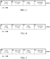
- FIG. 3 to FIG. 5 shows the sequential modes of operation of an impulse radar, (e.g., for RF ranging) allocating the maximum time for radar transmission, in a repeating sequence of two modes.
- FIG. 3 to FIG. 5 also shows a "duty-cycle" optimization, where duty-cycle refers to the ratio of the gated modes to the non-gated modes.
- a gated mode 80 is interleaved with a non-gated mode 82, each with an equal duration (e.g., 5 ms).
- FIG. 4 shows an embodiment favoring short-range targets, at the expense of SNR for long-range targets.
- the duration of the gated mode 90 (e.g., 1 ms) is less than the duration of the non-gated mode 92 (e.g., 9 ms).
- FIG. 5 shows an embodiment favoring long-range targets, at the expense of SNR for short-range targets.
- the duration of the gated mode 100 (e.g., 9.5 ms) is greater than the duration of the non-gated mode 102 (e.g., 0.5 ms).
- the relative durations of the gated mode and the non-gated mode is dynamically adjusted based on a variety of criteria as discussed above. It should be appreciated that the durations of the gated modes, non-gated modes and deactivated modes of FIG. 3 to FIG. 5 are shown as example embodiments and not to limit the disclosure to other embodiments having different durations of the these modes.
- FIG. 6 to FIG. 8 shows the sequential modes of operation of an impulse radar, (e.g., for RF ranging) for a reduced energy operation, in a repeating sequence of three modes.
- a gated mode 110 is interleaved with a non-gated mode 112 and a deactivated mode 114. While both the gated mode 110 and non-gated modes 112 have an equal duration of 5 ms, (and thus equal weighting for long-range and short-range targets), the deactivated mode 114 is substantially longer at 90 ms to reduce energy consumption. In one embodiment, the deactivated mode 114 reduces energy consumption by deactivating the transceiver.
- FIG. 1 shows the sequential modes of operation of an impulse radar, (e.g., for RF ranging) for a reduced energy operation, in a repeating sequence of three modes.
- a gated mode 110 is interleaved with a non-gated mode 112 and a deactivated mode 114. While both the gated mode 110 and
- FIG. 7 shows an embodiment favoring short-range targets, at the expense of SNR for long-range targets.
- the duration of the gated mode 130 e.g., 1 ms
- the duration of the non-gated mode 132 e.g., 9 ms
- the deactivated mode 134 is substantially longer at 90 ms to reduce energy consumption.
- FIG. 8 shows an embodiment favoring long-range targets, at the expense of SNR for short-range targets.
- the duration of the gated mode 150 e.g., 9.5 ms
- the deactivated mode 154 is substantially longer at 90 ms to reduce energy consumption.
- the relative durations of the gated mode and the non-gated mode are dynamically adjusted based on a variety of criteria as discussed above. It should be appreciated that the durations of the gated modes, non-gated modes and deactivated modes are shown as example embodiments and not to limit the disclosure to other embodiments having different durations of the these modes.
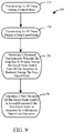
- FIG. 9 with reference to FIG. 1 shows a method 170 for operating an impulse radar using variable pulse repetition frequency.
- an RF pulse is transmitted (e.g., with a transmitter 20), during a gated mode.
- an RF pulse is transmitted during a non-gated mode.
- a returned transmission is received (e.g., with a receiver 32).
- the amplifier of the receiver is blinded during the gated mode.
- a gain of the amplifier of the receiver is reduced during the non-gated mode.
- a first duration of the gated mode and/or a second duration of the non-gated mode is adjusted (e.g., with a controller 34), in response to a maximum duty-cycle operation.
- FIG. 10 with reference to FIG. 1 shows a method 180 for operating an impulse radar using variable pulse repetition frequency.
- an RF pulse is transmitted (e.g., with a transmitter 20), during a gated mode.
- an RF pulse is transmitted during a non-gated mode.
- the transmitter e.g., transmitter 20
- the transceiver including both the transmitter 20 and the receiver 32 is deactivated.
- a returned transmission is received (e.g., with a receiver 32).
- the amplifier of the receiver is blinded during the gated mode. A gain of the amplifier of the receiver is reduced during the non-gated mode.
- a first duration of the gated mode and/or a second duration of the non-gated mode and/or a third duration of the deactivated mode is adjusted (e.g., with a controller 34), in response to a reduced-energy operation.
- an apparatus comprises a transmitter comprising a pulsed Radio Frequency (RF) source coupled to an antenna.
- a receiver comprises an amplifier coupled to the antenna.
- a controller is configured to adjust one or more durations of a ranging cycle of the apparatus, wherein the ranging cycle comprises a first duration of a gated mode and a second duration of a non-gated mode, the gated mode blinding the amplifier during a transmission of the transmitter, and the non-gated mode reducing a gain of the amplifier during the transmission.
- the ranging cycle further comprises a third duration of a deactivated mode, wherein the deactivated mode comprises deactivating the transmitter.
- the apparatus is temporally shared for a plurality of ranging applications.
- a passive target is capable of reflecting the transmission towards the antenna.
- An active target is configured to receive the transmission from the transmitter and to transmit a second transmission towards the antenna.
- the controller comprises machine-learning circuitry configured to identify a target classification of one or more targets within a range of the apparatus.
- a method for operating an impulse radar using variable pulse repetition frequency comprises transmitting a Radio Frequency (RF) pulse during a gated mode with a transmitter.
- the transmitter comprises an antenna.
- the RF pulse is transmitted during a non-gated mode with the transmitter.
- a returned transmission is received from at least one target with a receiver comprising blinding the amplifier while transmitting during the gated mode and reducing a gain of the amplifier while transmitting during the non-gated mode, wherein the receiver comprises an amplifier coupled to the antenna.
- At least one of a first duration of the gated mode and a second duration of the non-gated mode is adjusted in response to a maximum duty-cycle operation.
- Alternative embodiments of the method for operating an impulse radar using variable pulse repetition frequency include one of the following features, or any combination thereof.
- the impulse radar is temporally shared for a plurality of targets.
- At least one of the first duration and the second duration is adjusted based on a detected first number of short-range targets and a detected second number of long-range targets.
- At least one of the first duration and the second duration is adjusted based on a required first Signal to Noise Ratio (SNR) margin of the at least one target being a short-range target and required second SNR margin of the at least one target being a large-range target.
- At least one of the first duration and the second duration is adjusted based on one or more predefined parameters.
- At least one of the first duration and the second duration is adjusted based on an inferred classification of the at least one target. The inferred classification of the at least one target is inferred using machine learning of a relative movement of the at least one target and another target.
- a method for operating an impulse radar using variable pulse repetition frequency comprises transmitting a Radio Frequency (RF) pulse during a gated mode with a transmitter.
- the transmitter comprises an antenna.
- the RF pulse is transmitted during a non-gated mode with the transmitter.
- the transmitter is deactivated during a deactivated mode.
- a returned transmission is received from at least one target with a receiver comprising blinding the amplifier while transmitting during the gated mode and reducing a gain of the amplifier while transmitting during the non-gated mode, wherein the receiver comprises an amplifier coupled to the antenna.
- At least one of a first duration of the gated mode, a second duration of the non-gated mode and a third duration of the deactivated mode is adjusted in response to a reduced-energy operation.
- Alternative embodiments of the method for operating an impulse radar using variable pulse repetition frequency include one of the following features, or any combination thereof.
- the impulse radar is temporally shared for a plurality of targets.
- At least one of the first duration and the second duration is adjusted based on a detected first number of short-range targets and a detected second number of long-range targets.
- At least one of the first duration and the second duration is adjusted based on a required first Signal to Noise Ratio (SNR) margin of the at least one target being a short-range target and required second SNR margin of the at least one target being a large-range target.
- At least one of the first duration and the second duration is adjusted based on one or more predefined parameters.
- At least one of the first duration and the second duration is adjusted based on an inferred classification of the at least one target. The inferred classification of the at least one target is inferred using machine learning of a relative movement of the at least one target and another target.
Landscapes
- Engineering & Computer Science (AREA)
- Radar, Positioning & Navigation (AREA)
- Remote Sensing (AREA)
- Physics & Mathematics (AREA)
- Computer Networks & Wireless Communication (AREA)
- General Physics & Mathematics (AREA)
- Electromagnetism (AREA)
- Radar Systems Or Details Thereof (AREA)
Abstract
Description
- This disclosure relates generally to radar systems, and more specifically to an impulse radar having both long-range and short-range detection capability.
- RF ranging systems employ a Time-Of-Flight (TOF) principle to determine a distance between a transmitter and a target. Typically, a transmitter transmits a waveform towards the target. The waveform is then reflected or retransmitted by the target towards a receiver. The duration of time for the reflection or retransmission to reach the receiver, determines the distance between the transmitter and the target.
- Examples of targets include distant targets, with relatively weak reflectivity, and nearby targets, which reflect a stronger signal towards the receiver. Monostatic radars combine the transmitter and receiver antennas to reduce a cost of an RF ranging system. However, monostatic radars have not been able to operate in both long-range and short-range modes, thus limiting their application.
- Aspects of the disclosure are defined in the accompanying claims.
- In a first aspect, there is provided an apparatus comprising: a transmitter comprising a pulsed Radio Frequency (RF) source coupled to an antenna; a receiver comprising an amplifier coupled to the antenna; and a controller configured to adjust one or more durations of a ranging cycle of the apparatus, wherein the ranging cycle comprises a first duration of a gated mode and a second duration of a non-gated mode, the gated mode blinding the amplifier during a transmission of the transmitter, and the non-gated mode reducing a gain of the amplifier during the transmission.
- In one or more embodiments, the ranging cycle may further comprise a third duration of a deactivated mode, wherein the deactivated mode comprises deactivating the transmitter.
- In one or more embodiments, the apparatus may be temporally shared for a plurality of ranging applications.
- In one or more embodiments, the apparatus may further comprise a passive target capable of reflecting the transmission towards the antenna.
- In one or more embodiments, the apparatus may further comprise an active target configured to receive the transmission from the transmitter and to transmit a second transmission towards the antenna.
- In one or more embodiments, the controller may comprise machine-learning circuitry configured to identify a target classification of one or more targets within a range of the apparatus.
- In a second aspect, there is provided a method for operating an impulse radar using variable pulse repetition frequency comprising: transmitting a Radio Frequency (RF) pulse during a gated mode with a transmitter, the transmitter comprising an antenna; transmitting the RF pulse during a non-gated mode with the transmitter; receiving a returned transmission from at least one target with a receiver comprising blinding the amplifier while transmitting during the gated mode and reducing a gain of the amplifier while transmitting during the non-gated mode, wherein the receiver comprises an amplifier coupled to the antenna; and adjusting at least one of a first duration of the gated mode and a second duration of the non-gated mode in response to a maximum duty-cycle operation.
- In one or more embodiments, the method may further comprise temporally sharing the impulse radar for a plurality of targets.
- In one or more embodiments, the method may further comprise adjusting at least one of the first duration and the second duration based on a detected first number of short-range targets and a detected second number of long-range targets.
- In one or more embodiments, the method may further comprise adjusting at least one of the first duration and the second duration based on a required first Signal to Noise Ratio (SNR) margin of the at least one target being a short-range target and required second SNR margin of the at least one target being a large-range target.
- In one or more embodiments, the method may further comprise adjusting at least one of the first duration and the second duration based on one or more predefined parameters.
- In one or more embodiments, the method may further comprise adjusting at least one of the first duration and the second duration based on an inferred classification of the at least one target.
- In one or more embodiments, the method may further comprise inferring the inferred classification of the at least one target using machine learning of a relative movement of the at least one target and another target.
- In a third aspect, there is provided a method for operating an impulse radar using variable pulse repetition frequency comprising: transmitting a Radio Frequency (RF) pulse during a gated mode with a transmitter, the transmitter comprising an antenna; transmitting the RF pulse during a non-gated mode with the transmitter; deactivating the transmitter during a deactivated mode; receiving a returned transmission from at least one target with a receiver comprising blinding the amplifier while transmitting during the gated mode and reducing a gain of the amplifier while transmitting during the non-gated mode, wherein the receiver comprises an amplifier coupled to the antenna; and adjusting at least one of a first duration of the gated mode, a second duration of the non-gated mode and a third duration of the deactivated mode in response to a reduced-energy operation.
- In one or more embodiments, the method may further comprise temporally sharing the impulse radar for a plurality of targets.
- In one or more embodiments, the method may further comprise adjusting at least one of the first duration and the second duration based on a detected first number of short-range targets and a detected second number of long-range targets.
- In one or more embodiments, the method may further comprise adjusting at least one of the first duration and the second duration based on a required first Signal to Noise Ratio (SNR) margin of the at least one target being a short-range target and required second SNR margin of the at least one target being a large-range target.
- In one or more embodiments, the method may further comprise adjusting at least one of the first duration and the second duration based on one or more predefined parameters.
- In one or more embodiments, the method may further comprise adjusting at least one of the first duration and the second duration based on an inferred classification of the at least one target.
- In one or more embodiments, the method may further comprise inferring the inferred classification of the at least one target using machine learning of a relative movement of the at least one target and another target.
- The present invention is illustrated by way of example and is not limited by the accompanying figures, in which like references indicate similar elements. Elements in the figures are illustrated for simplicity and clarity and have not necessarily been drawn to scale.
-
FIG. 1 is a schematic view of an example embodiment of a Radio Frequency (RF) ranging system. -
FIG. 2 is a schematic view of an example embodiment of a monostatic pulsed radar system. -
FIG. 3, FIG. 4 and FIG. 5 are timing diagram views showing sequential modes of operation of an impulse radar, in accordance with an example embodiment of the present disclosure. -
FIG. 6, FIG. 7 and FIG. 8 are timing diagram views showing sequential modes of operation of an impulse radar, in accordance with another example embodiment of the present disclosure. -
FIG. 9 is a flowchart representation of a method for operating an impulse radar using variable pulse repetition frequency, in accordance with an example embodiment of the present disclosure. -
FIG. 10 is a flowchart representation of a method for operating an impulse radar using variable pulse repetition frequency, in accordance with an example embodiment of the present disclosure. - Embodiments described herein provide for a pulsed radar system alternatively operating in both a long-range (e.g., gated mode), and a short-range (e.g., non-gated mode). In the long-range mode, receiver blindness is supported for higher available Signal to Noise Ratio (SNR). In the short-range mode, the receiver detects target reflections or retransmissions overlapping with a direct feed-through signal from the mono-static transmitter to the receiver. Accordingly, the pulsed (e.g., impulse), radar systems described herein offer cost competitive detection of both short-range and long-range targets, as well as a dynamic means to tune operating modes of the radar system based on a combination of target characteristics.
-
FIG. 1 shows anexample embodiment 10 of an RF ranging system, wherein a target retransmits a received waveform from a radar. It should be appreciated that the teachings of this disclosure apply to both monostatic radars having a collocated transmitter and receiver, and bistatic radars having a transmitter and receiver having a substantial separation therebetween. Furthermore, this disclosure is contemplated to be implemented in either monostatic or bistatic radar embodiments with either passive targets (e.g., reflecting a received signal), or active targets (e.g, actively retransmitting the received signal). Theembodiment 10 employs the TOF principle to determine a distance between two objects, or markers on objects. Specifically, theembodiment 10 includes aradar 12 and atarget 14. Theradar 12 transmits, with atransmitter 20, a waveform (e.g., a chirp or a pulse) over apath 22 to areceiver 24. The waveform travels across thepath 22 as a "challenge" to thetarget 14 and with an elapsed transit time equal to "TOP-1." Thereceiver 24 transfers a request over anet 26 to atransmitter 28, with an elapsed processing time equal to "Tproc." Thetransmitter 28 transmits a second transmission over apath 30 to areceiver 32 of theradar 12. The second transmission is a "response" to the challenge of theradar 12 and transits thepath 30 with a transit time equal to "TOF-2." - A
controller 34 controls the operations of thetransmitter 20 and the receive 32 overrespective nets transmitter 20, and starts the calculation of the distance between theradar 12 and thetarget 14 with a Round-Trip Time of Flight ("RTToF")counter 40. Thetransmitter 20 starts thecounter 40 with a start request onnet 42 to establish astart time 44. Thereceiver 32 stops thecounter 40 with a stop request onnet 46 to establish astop time 48. The time difference between thestart time 44 and thestop time 48 is a measured time (Tmeas). Similarly, thetarget 14 measures a processing time (Tproc) with acounter 50, by measuring a time difference between atime 52, when thereceiver 24 receives the waveform from thetransmitter 20, and atime 54, when thetransmitter 28 transmits the second waveform to thereceiver 32. Accordingly, the distance (D) between theradar 12 and thetarget 14 is given by the following equation (1), wherein "c" is the speed of light in the medium comprising thepaths 
- In another embodiment, wherein the
target 14 passively reflects the waveform transmitted by thetransmitter 20, the processing time Tproc is zero, hence inequation 1. In example embodiments of a radar based on an Impulse-Radio Ultra-Wide Band ("IR UWB") protocol based on IEEE 802.15.4 High Rate Pulse (HRP) repetition frequency UWB operating between approximately 3 GHz and 10 GHz, the radar transceiver operates either as a bistatic or a monostatic radar.FIG. 2 shows anexample embodiment 60 including atransceiver 62 and atarget 64. Theembodiment 60 is configured as a monostatic radar, wherein a collocated transmitter and receiver form atransceiver 62. In one embodiment, thetransceiver 62 includes a transmitter and a receiver having respective antennas in close proximity. In another embodiment, the transmitter and receiver share thesame antenna 66, the reduce the cost of the RF ranging system. - In the
embodiment 60 of the monostatic radar, a pulse is transmitted by thetransceiver 62 towards thetarget 64, and then a reflected pulse (e.g., second transmission) 68 is reflected by thetarget 64. A distance (or range) 70 between thetransceiver 62 and thetarget 64 is calculated using the methods described forFIG. 1 . For targets that are physically close to thetransceiver 62, aradar blind range 72 exists, when thetransceiver 62 transmits in a gated mode, because the reflectedpulse 68 returns to thetransceiver 62 while the receiving portion of thetransceiver 62 is blinded. The term "blinded" in this context means that the receiver ignores received waveforms through one or more techniques, including but not limited to, deactivating an amplifier of the receiver, or gating an output of the amplifier. - In one example embodiment of a monostatic radar, as shown in
FIG. 2 , a relatively low-cost radar is implemented to perform functions such as (human) presence detection, respiration rate monitoring or heartbeat monitoring. As a specific case, where an IR-UWB radio is primarily used for vehicular access, a radar mode of an externally mounted transceiver allows the re-use of the same hardware to act as a parking sensor (e.g., to be used for autonomous remote parking). Similarly, in another embodiment, an internally mounted IR-UWB transceiver is used for in-cabin radar monitoring or gesture control in an automobile. - In embodiments of RF ranging systems, such as the one described in
FIG. 1 andFIG. 2 , it is desirable to maximize security and link budget while minimizing current consumption, latency, and system cost. Accordingly, in one example embodiment, the RF ranging system is based on an IR-UWB transceiver (e.g., using a protocol based on IEEE 802.15.4 HRP UWB). IR-UWB transceivers offer a means to support pulse radar functionality, with pulse transmitters, receivers that are designed to provide accurate estimates of the Channel Impulse Response (CIR), and the ability to support both transmit and receive functions using asingle antenna 66. - With efficient Digital Signal Processor (DSP) algorithms, included for example in the
controller 34, the link budget is primarily determined by receiver sensitivity, as the transmitter tends to be limited by the average or mean power spectral density regulations (e.g., -41.3 dBm/MHz for UWB devices under FCC Part 15 and/or ETSI EN 302 065). - In a traditional pulse radar using a gated mode, the receiver can be blind during transmission, meaning that a monostatic pulse radar, unlike its Continuous-Wave (CW) counterpart, need not reduce the receiver gain during signal reception due to signals from the transmitter reaching the receiver with large amplitudes (e.g., from direct transmitter to receiver feed-through coupling). This larger receiver gain afforded by the gated mode, results in better receiver sensitivity (e.g., it allows a pulse radar to achieve a larger link budget than a CW radar at equal average transmit power).
- For an example embodiment of a short-range radar, receiver blindness is not allowed, as reflections of interest may (partially) overlap with (direct-feedthrough) signals from the transmitter appearing at the receiver. For example, with a typical UWB pulse shape, a typical pulse duration of approximately 10 ns would impose a blind time corresponding to approximately 1.5 meters round-trip time-of-flight (e.g., targets closer than 1.5 meters would not be detected, as shown by the
radar blind range 72 ofFIG. 2 ). This scenario is worse if blinding the receiver requires additional time for mode-switching, which is typically the case. A typical radarblind range 72 of several meters is common when mode-switching is considered in a gated mode RF ranging system. The embodiments described herein, alternate the mode of operation of a pulse radar between a gated (e.g., long-range) mode and a non-gated (e.g., short-range) mode. The characteristics of a gated mode and a non-gated mode radar system are compared in Table 1 below.Table 1: Properties of Gated and Non-Gated modes Gated Pulse Radar Mode Non-Gated Pulse Radar Mode Low Pulse Repetition Frequency High Pulse Repetition Frequency High receiver gain -> High SNR Reduced receiver Gain -> Reduced SNR Blind at short range Functional at short range Trivial CIR de-convolution DSP-intensive CIR de-convolution Weak false alarm resistance Strong false alarm resistance Requires large pulse amplitudes to fill given mean power spectral mask Requires large transmitter duty-cycle to fill given mean power spectral mask - Example embodiments of RF ranging systems described herein adjust the relative durations of a gated mode and a non-gated mode (and in some embodiments, also a deactivated mode). Adjusting the relative durations of these modes occurs dynamically based on one or more of the following criteria. In one example embodiment, the relative duration (or duty cycle) of the gated and non-gated modes is adjusted based on the number of detected short-range targets relative to the number of long-range targets. For example, when a majority of the detected targets are short-range, additional time is allocated to a non-gate mode operation. In another example embodiment, the SNR margin of short-range targets relative to the SNR margin of long-range targets is used. The required SNR for short-range targets is typically less than for long-range targets because short-range targets reflect more signal power. In another example embodiment, a predefined ratio of gated mode duration and non-gated mode duration is defined for a programmed or set use case. For example, a radar used for gesture control prioritizes short-range detection of hand movements.
- In another example embodiment, the target type or classification is inferred based on observed target characteristics, including but not limited to, reflected signal strength and relative movements between two or more detected targets or between a detected target and the RF transceiver. In another example embodiment, inferring target classifications or types include using machine learning and/or artificial intelligence.
-
FIG. 3 to FIG. 5 shows the sequential modes of operation of an impulse radar, (e.g., for RF ranging) allocating the maximum time for radar transmission, in a repeating sequence of two modes.FIG. 3 to FIG. 5 also shows a "duty-cycle" optimization, where duty-cycle refers to the ratio of the gated modes to the non-gated modes. InFIG. 3 agated mode 80 is interleaved with anon-gated mode 82, each with an equal duration (e.g., 5 ms).FIG. 4 shows an embodiment favoring short-range targets, at the expense of SNR for long-range targets. Here, the duration of the gated mode 90 (e.g., 1 ms) is less than the duration of the non-gated mode 92 (e.g., 9 ms).FIG. 5 shows an embodiment favoring long-range targets, at the expense of SNR for short-range targets. Here, the duration of the gated mode 100 (e.g., 9.5 ms) is greater than the duration of the non-gated mode 102 (e.g., 0.5 ms). - In one embodiment, the relative durations of the gated mode and the non-gated mode is dynamically adjusted based on a variety of criteria as discussed above. It should be appreciated that the durations of the gated modes, non-gated modes and deactivated modes of
FIG. 3 to FIG. 5 are shown as example embodiments and not to limit the disclosure to other embodiments having different durations of the these modes. -
FIG. 6 to FIG. 8 shows the sequential modes of operation of an impulse radar, (e.g., for RF ranging) for a reduced energy operation, in a repeating sequence of three modes. InFIG. 6 agated mode 110 is interleaved with anon-gated mode 112 and a deactivatedmode 114. While both thegated mode 110 andnon-gated modes 112 have an equal duration of 5 ms, (and thus equal weighting for long-range and short-range targets), the deactivatedmode 114 is substantially longer at 90 ms to reduce energy consumption. In one embodiment, the deactivatedmode 114 reduces energy consumption by deactivating the transceiver.FIG. 7 shows an embodiment favoring short-range targets, at the expense of SNR for long-range targets. Here, the duration of the gated mode 130 (e.g., 1 ms) is less than the duration of the non-gated mode 132 (e.g., 9 ms). Similar toFIG. 6 , the deactivatedmode 134 is substantially longer at 90 ms to reduce energy consumption.FIG. 8 shows an embodiment favoring long-range targets, at the expense of SNR for short-range targets. Here, the duration of the gated mode 150 (e.g., 9.5 ms) is greater than the duration of the non-gated mode 152 (e.g., 0.5 ms). Similar toFIG. 6 , the deactivatedmode 154 is substantially longer at 90 ms to reduce energy consumption. - In one embodiment, the relative durations of the gated mode and the non-gated mode are dynamically adjusted based on a variety of criteria as discussed above. It should be appreciated that the durations of the gated modes, non-gated modes and deactivated modes are shown as example embodiments and not to limit the disclosure to other embodiments having different durations of the these modes.
-
FIG. 9 with reference toFIG. 1 shows amethod 170 for operating an impulse radar using variable pulse repetition frequency. At 172, an RF pulse is transmitted (e.g., with a transmitter 20), during a gated mode. At 174, an RF pulse is transmitted during a non-gated mode. At 176, a returned transmission is received (e.g., with a receiver 32). The amplifier of the receiver is blinded during the gated mode. A gain of the amplifier of the receiver is reduced during the non-gated mode. At 178, a first duration of the gated mode and/or a second duration of the non-gated mode (e.g.,FIG. 3 to FIG. 5 ) is adjusted (e.g., with a controller 34), in response to a maximum duty-cycle operation. -
FIG. 10 with reference toFIG. 1 shows amethod 180 for operating an impulse radar using variable pulse repetition frequency. At 182, an RF pulse is transmitted (e.g., with a transmitter 20), during a gated mode. At 184, an RF pulse is transmitted during a non-gated mode. At 186, the transmitter (e.g., transmitter 20) is deactivated. In another embodiment, the transceiver, including both thetransmitter 20 and thereceiver 32 is deactivated. At 188, a returned transmission is received (e.g., with a receiver 32). The amplifier of the receiver is blinded during the gated mode. A gain of the amplifier of the receiver is reduced during the non-gated mode. At 190, a first duration of the gated mode and/or a second duration of the non-gated mode and/or a third duration of the deactivated mode (e.g.,FIG. 6 to FIG. 8 ) is adjusted (e.g., with a controller 34), in response to a reduced-energy operation. - As will be appreciated, embodiments as disclosed include at least the following. In one embodiment, an apparatus comprises a transmitter comprising a pulsed Radio Frequency (RF) source coupled to an antenna. A receiver comprises an amplifier coupled to the antenna. A controller is configured to adjust one or more durations of a ranging cycle of the apparatus, wherein the ranging cycle comprises a first duration of a gated mode and a second duration of a non-gated mode, the gated mode blinding the amplifier during a transmission of the transmitter, and the non-gated mode reducing a gain of the amplifier during the transmission.
- Alternative embodiments of the apparatus include one of the following features, or any combination thereof. The ranging cycle further comprises a third duration of a deactivated mode, wherein the deactivated mode comprises deactivating the transmitter. The apparatus is temporally shared for a plurality of ranging applications. A passive target is capable of reflecting the transmission towards the antenna. An active target is configured to receive the transmission from the transmitter and to transmit a second transmission towards the antenna. The controller comprises machine-learning circuitry configured to identify a target classification of one or more targets within a range of the apparatus.
- In another embodiment, a method for operating an impulse radar using variable pulse repetition frequency comprises transmitting a Radio Frequency (RF) pulse during a gated mode with a transmitter. The transmitter comprises an antenna. The RF pulse is transmitted during a non-gated mode with the transmitter. A returned transmission is received from at least one target with a receiver comprising blinding the amplifier while transmitting during the gated mode and reducing a gain of the amplifier while transmitting during the non-gated mode, wherein the receiver comprises an amplifier coupled to the antenna. At least one of a first duration of the gated mode and a second duration of the non-gated mode is adjusted in response to a maximum duty-cycle operation.
- Alternative embodiments of the method for operating an impulse radar using variable pulse repetition frequency include one of the following features, or any combination thereof. The impulse radar is temporally shared for a plurality of targets. At least one of the first duration and the second duration is adjusted based on a detected first number of short-range targets and a detected second number of long-range targets. At least one of the first duration and the second duration is adjusted based on a required first Signal to Noise Ratio (SNR) margin of the at least one target being a short-range target and required second SNR margin of the at least one target being a large-range target. At least one of the first duration and the second duration is adjusted based on one or more predefined parameters. At least one of the first duration and the second duration is adjusted based on an inferred classification of the at least one target. The inferred classification of the at least one target is inferred using machine learning of a relative movement of the at least one target and another target.
- In another embodiment, a method for operating an impulse radar using variable pulse repetition frequency comprises transmitting a Radio Frequency (RF) pulse during a gated mode with a transmitter. The transmitter comprises an antenna. The RF pulse is transmitted during a non-gated mode with the transmitter. The transmitter is deactivated during a deactivated mode. A returned transmission is received from at least one target with a receiver comprising blinding the amplifier while transmitting during the gated mode and reducing a gain of the amplifier while transmitting during the non-gated mode, wherein the receiver comprises an amplifier coupled to the antenna. At least one of a first duration of the gated mode, a second duration of the non-gated mode and a third duration of the deactivated mode is adjusted in response to a reduced-energy operation.
- Alternative embodiments of the method for operating an impulse radar using variable pulse repetition frequency include one of the following features, or any combination thereof. The impulse radar is temporally shared for a plurality of targets. At least one of the first duration and the second duration is adjusted based on a detected first number of short-range targets and a detected second number of long-range targets. At least one of the first duration and the second duration is adjusted based on a required first Signal to Noise Ratio (SNR) margin of the at least one target being a short-range target and required second SNR margin of the at least one target being a large-range target. At least one of the first duration and the second duration is adjusted based on one or more predefined parameters. At least one of the first duration and the second duration is adjusted based on an inferred classification of the at least one target. The inferred classification of the at least one target is inferred using machine learning of a relative movement of the at least one target and another target.
- Although the invention is described herein with reference to specific embodiments, various modifications and changes can be made without departing from the scope of the present invention as set forth in the claims below. Accordingly, the specification and figures are to be regarded in an illustrative rather than a restrictive sense, and all such modifications are intended to be included within the scope of the present invention. Any benefits, advantages, or solutions to problems that are described herein with regard to specific embodiments are not intended to be construed as a critical, required, or essential feature or element of any or all the claims.
- Unless stated otherwise, terms such as "first" and "second" are used to arbitrarily distinguish between the elements such terms describe. Thus, these terms are not necessarily intended to indicate temporal or other prioritization of such elements.
Claims (13)
- An apparatus comprising:a transmitter comprising a pulsed Radio Frequency (RF) source coupled to an antenna;a receiver comprising an amplifier coupled to the antenna; anda controller configured to adjust one or more durations of a ranging cycle of the apparatus, wherein the ranging cycle comprises a first duration of a gated mode and a second duration of a non-gated mode, the gated mode blinding the amplifier during a transmission of the transmitter, and the non-gated mode reducing a gain of the amplifier during the transmission.
- The apparatus of claim 1 wherein the ranging cycle further comprises a third duration of a deactivated mode, wherein the deactivated mode comprises deactivating the transmitter.
- The apparatus of any preceding claim wherein the apparatus is temporally shared for a plurality of ranging applications.
- The apparatus of any preceding claim further comprising a passive target capable of reflecting the transmission towards the antenna.
- The apparatus of any preceding claim further comprising an active target configured to receive the transmission from the transmitter and to transmit a second transmission towards the antenna.
- The apparatus of any preceding claim wherein the controller comprises machine-learning circuitry configured to identify a target classification of one or more targets within a range of the apparatus.
- A method for operating an impulse radar using variable pulse repetition frequency comprising:transmitting a Radio Frequency (RF) pulse during a gated mode with a transmitter, the transmitter comprising an antenna;transmitting the RF pulse during a non-gated mode with the transmitter;receiving a returned transmission from at least one target with a receiver comprising blinding the amplifier while transmitting during the gated mode and reducing a gain of the amplifier while transmitting during the non-gated mode, wherein the receiver comprises an amplifier coupled to the antenna; andadjusting at least one of a first duration of the gated mode and a second duration of the non-gated mode in response to a maximum duty-cycle operation.
- The method of claim 7 further comprising temporally sharing the impulse radar for a plurality of targets.
- The method of claim 7 or 8 further comprising adjusting at least one of the first duration and the second duration based on a detected first number of short-range targets and a detected second number of long-range targets.
- The method of any of claims 7 to 9 further comprising adjusting at least one of the first duration and the second duration based on a required first Signal to Noise Ratio (SNR) margin of the at least one target being a short-range target and required second SNR margin of the at least one target being a large-range target.
- The method of any of claims 7 to 10 further comprising adjusting at least one of the first duration and the second duration based on one or more predefined parameters.
- The method of any of claims 7 to 11 further comprising adjusting at least one of the first duration and the second duration based on an inferred classification of the at least one target.
- The method of claim 12 further comprising inferring the inferred classification of the at least one target using machine learning of a relative movement of the at least one target and another target.
Applications Claiming Priority (1)
| Application Number | Priority Date | Filing Date | Title |
|---|---|---|---|
| US16/558,478 US11714183B2 (en) | 2019-09-03 | 2019-09-03 | Impulse radar using variable pulse repetition frequency |
Publications (2)
| Publication Number | Publication Date |
|---|---|
| EP3789791A1 true EP3789791A1 (en) | 2021-03-10 |
| EP3789791B1 EP3789791B1 (en) | 2025-07-23 |
Family
ID=72039467
Family Applications (1)
| Application Number | Title | Priority Date | Filing Date |
|---|---|---|---|
| EP20190352.3A Active EP3789791B1 (en) | 2019-09-03 | 2020-08-10 | Impulse radar using variable pulse repetition frequency |
Country Status (3)
| Country | Link |
|---|---|
| US (1) | US11714183B2 (en) |
| EP (1) | EP3789791B1 (en) |
| CN (1) | CN112444804A (en) |
Families Citing this family (4)
| Publication number | Priority date | Publication date | Assignee | Title |
|---|---|---|---|---|
| US11714183B2 (en) * | 2019-09-03 | 2023-08-01 | Nxp B.V. | Impulse radar using variable pulse repetition frequency |
| US20220043135A1 (en) * | 2020-08-05 | 2022-02-10 | Rockwell Automation Technologies, Inc. | Automatic device ordering |
| EP4155755B1 (en) * | 2021-09-24 | 2025-07-02 | Magna Electronics Sweden AB | Radar resource requirement prediction |
| US12379458B2 (en) | 2022-10-06 | 2025-08-05 | Nxp B.V. | Method and radar system for detecting targeted radar interference |
Citations (3)
| Publication number | Priority date | Publication date | Assignee | Title |
|---|---|---|---|---|
| US20120235857A1 (en) * | 2011-03-16 | 2012-09-20 | Electronics And Telecommunications Research Institute | Radar apparatus supporting short and long range radar operation |
| US20150285897A1 (en) * | 2014-03-31 | 2015-10-08 | Honeywell International Inc. | Hybrid radar system combining fmcw radar and pulsed radar |
| US20190212438A1 (en) * | 2018-01-10 | 2019-07-11 | Mando Corporation | Apparatus and method for controlling radar |
Family Cites Families (11)
| Publication number | Priority date | Publication date | Assignee | Title |
|---|---|---|---|---|
| US9618605B2 (en) * | 2011-12-30 | 2017-04-11 | Flir Systems, Inc. | Radar system providing multiple waveforms for long range and short range target detection |
| KR102038533B1 (en) * | 2012-06-14 | 2019-10-31 | 한국전자통신연구원 | Laser Radar System and Method for Acquiring Target Image |
| US9891311B2 (en) | 2014-07-30 | 2018-02-13 | Nxp B.V. | Method of secure RF ranging under strong multipath reflections |
| US9470777B2 (en) * | 2014-09-19 | 2016-10-18 | Delphi Technologies, Inc. | Radar system for automated vehicle with phase change based target catagorization |
| US10578708B2 (en) * | 2016-04-08 | 2020-03-03 | Raytheon Company | Switchable transmit/receive (T/R) module |
| US11835645B2 (en) * | 2016-06-14 | 2023-12-05 | Mediatek Inc. | Reconfigurable RF front end and antenna arrays for radar mode switching |
| US20180314253A1 (en) * | 2017-05-01 | 2018-11-01 | Mentor Graphics Development (Deutschland) Gmbh | Embedded automotive perception with machine learning classification of sensor data |
| EP3707526A2 (en) * | 2017-11-06 | 2020-09-16 | Echodyne Corp | Intelligent sensor and intelligent feedback-based dynamic control of a parameter of a field of regard to which the sensor is directed |
| US10175340B1 (en) * | 2018-04-27 | 2019-01-08 | Lyft, Inc. | Switching between object detection and data transfer with a vehicle radar |
| US11977144B2 (en) * | 2018-05-24 | 2024-05-07 | Nanowave Technologies Inc. | System and method for improved radar sensitivity |
| US11714183B2 (en) * | 2019-09-03 | 2023-08-01 | Nxp B.V. | Impulse radar using variable pulse repetition frequency |
-
2019
- 2019-09-03 US US16/558,478 patent/US11714183B2/en active Active
-
2020
- 2020-08-10 EP EP20190352.3A patent/EP3789791B1/en active Active
- 2020-08-26 CN CN202010874209.6A patent/CN112444804A/en active Pending
Patent Citations (3)
| Publication number | Priority date | Publication date | Assignee | Title |
|---|---|---|---|---|
| US20120235857A1 (en) * | 2011-03-16 | 2012-09-20 | Electronics And Telecommunications Research Institute | Radar apparatus supporting short and long range radar operation |
| US20150285897A1 (en) * | 2014-03-31 | 2015-10-08 | Honeywell International Inc. | Hybrid radar system combining fmcw radar and pulsed radar |
| US20190212438A1 (en) * | 2018-01-10 | 2019-07-11 | Mando Corporation | Apparatus and method for controlling radar |
Non-Patent Citations (1)
| Title |
|---|
| OBEID N ET AL: "Millimeter Wave Ultra Wide Band Short Range Radar Localization Accuracy", 2009 IEEE 69TH VEHICULAR TECHNOLOGY CONFERENCE; APRIL 26-29, 2009, BARCELONA, SPAIN, IEEE, PISCATAWAY, NJ, USA, 26 April 2009 (2009-04-26), pages 1 - 5, XP031474616, ISBN: 978-1-4244-2517-4 * |
Also Published As
| Publication number | Publication date |
|---|---|
| EP3789791B1 (en) | 2025-07-23 |
| US11714183B2 (en) | 2023-08-01 |
| CN112444804A (en) | 2021-03-05 |
| US20210063562A1 (en) | 2021-03-04 |
Similar Documents
| Publication | Publication Date | Title |
|---|---|---|
| EP3789791B1 (en) | Impulse radar using variable pulse repetition frequency | |
| EP0901642B1 (en) | Pulse homodyne field disturbance sensor | |
| US20220256519A1 (en) | Sensing in wireless communications system | |
| EP2616834B1 (en) | Object detection method, device and system | |
| US10444334B2 (en) | Controlling transmission of pulses from a sensor | |
| US8115674B2 (en) | Method of detecting target object and target object detection device | |
| AU692921B2 (en) | Range-gated field disturbance sensor with range-sensitivity compensation | |
| EP3971603A1 (en) | Radar interference mitigation | |
| EP4184195B1 (en) | System and method for facilitating detecting an external object | |
| US20230341510A1 (en) | Radar implementation in a communication device | |
| US8755424B2 (en) | Transmit power control | |
| US20240069184A1 (en) | Electronic device capable of adaptively adjusting power based on a distance from an object and operating method therefor | |
| US20250251492A1 (en) | Sub-Nyquist Hyperbolic Frequency Modulated Pulsed Radar for Accurate Range and Doppler Estimation | |
| JP2013238477A (en) | Radar device | |
| US12282090B2 (en) | Coherent, multi-static radar system, in particular for use in a vehicle | |
| JP2008525774A (en) | Radar system for monitoring targets in different distance ranges | |
| US20070216529A1 (en) | Intruder alarm | |
| EP4530664A1 (en) | Apparatus, radar system and method | |
| JP2011013182A (en) | Target detector and method of detecting target | |
| CN1727914B (en) | Radar set for back running | |
| JPH0666930A (en) | Radar apparatus | |
| EP2101192B1 (en) | A method and system for presence detection | |
| KR101640790B1 (en) | An apparatus for receiving a target signal of a mono-pulse antenna and method therfor | |
| Mylonopoulos et al. | Extended Automatic Repeat Request For Integrated Sensing And Communication Networks | |
| US20260086195A1 (en) | Radar device |
Legal Events
| Date | Code | Title | Description |
|---|---|---|---|
| PUAI | Public reference made under article 153(3) epc to a published international application that has entered the european phase |
Free format text: ORIGINAL CODE: 0009012 |
|
| STAA | Information on the status of an ep patent application or granted ep patent |
Free format text: STATUS: THE APPLICATION HAS BEEN PUBLISHED |
|
| AK | Designated contracting states |
Kind code of ref document: A1 Designated state(s): AL AT BE BG CH CY CZ DE DK EE ES FI FR GB GR HR HU IE IS IT LI LT LU LV MC MK MT NL NO PL PT RO RS SE SI SK SM TR |
|
| AX | Request for extension of the european patent |
Extension state: BA ME |
|
| STAA | Information on the status of an ep patent application or granted ep patent |
Free format text: STATUS: REQUEST FOR EXAMINATION WAS MADE |
|
| 17P | Request for examination filed |
Effective date: 20210910 |
|
| RBV | Designated contracting states (corrected) |
Designated state(s): AL AT BE BG CH CY CZ DE DK EE ES FI FR GB GR HR HU IE IS IT LI LT LU LV MC MK MT NL NO PL PT RO RS SE SI SK SM TR |
|
| STAA | Information on the status of an ep patent application or granted ep patent |
Free format text: STATUS: EXAMINATION IS IN PROGRESS |
|
| 17Q | First examination report despatched |
Effective date: 20230103 |
|
| GRAP | Despatch of communication of intention to grant a patent |
Free format text: ORIGINAL CODE: EPIDOSNIGR1 |
|
| STAA | Information on the status of an ep patent application or granted ep patent |
Free format text: STATUS: GRANT OF PATENT IS INTENDED |
|
| INTG | Intention to grant announced |
Effective date: 20250415 |
|
| GRAS | Grant fee paid |
Free format text: ORIGINAL CODE: EPIDOSNIGR3 |
|
| GRAA | (expected) grant |
Free format text: ORIGINAL CODE: 0009210 |
|
| STAA | Information on the status of an ep patent application or granted ep patent |
Free format text: STATUS: THE PATENT HAS BEEN GRANTED |
|
| AK | Designated contracting states |
Kind code of ref document: B1 Designated state(s): AL AT BE BG CH CY CZ DE DK EE ES FI FR GB GR HR HU IE IS IT LI LT LU LV MC MK MT NL NO PL PT RO RS SE SI SK SM TR |
|
| REG | Reference to a national code |
Ref country code: GB Ref legal event code: FG4D |
|
| REG | Reference to a national code |
Ref country code: CH Ref legal event code: EP |
|
| REG | Reference to a national code |
Ref country code: DE Ref legal event code: R096 Ref document number: 602020054901 Country of ref document: DE |
|
| REG | Reference to a national code |
Ref country code: IE Ref legal event code: FG4D |
|
| PGFP | Annual fee paid to national office [announced via postgrant information from national office to epo] |
Ref country code: DE Payment date: 20250724 Year of fee payment: 6 |
|
| PGFP | Annual fee paid to national office [announced via postgrant information from national office to epo] |
Ref country code: GB Payment date: 20250822 Year of fee payment: 6 |
|
| PGFP | Annual fee paid to national office [announced via postgrant information from national office to epo] |
Ref country code: FR Payment date: 20250820 Year of fee payment: 6 |
|
| REG | Reference to a national code |
Ref country code: NL Ref legal event code: MP Effective date: 20250723 |
|
| PG25 | Lapsed in a contracting state [announced via postgrant information from national office to epo] |
Ref country code: PT Free format text: LAPSE BECAUSE OF FAILURE TO SUBMIT A TRANSLATION OF THE DESCRIPTION OR TO PAY THE FEE WITHIN THE PRESCRIBED TIME-LIMIT Effective date: 20251124 |
|
| PG25 | Lapsed in a contracting state [announced via postgrant information from national office to epo] |
Ref country code: NL Free format text: LAPSE BECAUSE OF FAILURE TO SUBMIT A TRANSLATION OF THE DESCRIPTION OR TO PAY THE FEE WITHIN THE PRESCRIBED TIME-LIMIT Effective date: 20250723 |
|
| REG | Reference to a national code |
Ref country code: AT Ref legal event code: MK05 Ref document number: 1816959 Country of ref document: AT Kind code of ref document: T Effective date: 20250723 |
|
| PG25 | Lapsed in a contracting state [announced via postgrant information from national office to epo] |
Ref country code: IS Free format text: LAPSE BECAUSE OF FAILURE TO SUBMIT A TRANSLATION OF THE DESCRIPTION OR TO PAY THE FEE WITHIN THE PRESCRIBED TIME-LIMIT Effective date: 20251123 |
|
| PG25 | Lapsed in a contracting state [announced via postgrant information from national office to epo] |
Ref country code: NO Free format text: LAPSE BECAUSE OF FAILURE TO SUBMIT A TRANSLATION OF THE DESCRIPTION OR TO PAY THE FEE WITHIN THE PRESCRIBED TIME-LIMIT Effective date: 20251023 |
|
| REG | Reference to a national code |
Ref country code: LT Ref legal event code: MG9D |
|
| PG25 | Lapsed in a contracting state [announced via postgrant information from national office to epo] |
Ref country code: AT Free format text: LAPSE BECAUSE OF FAILURE TO SUBMIT A TRANSLATION OF THE DESCRIPTION OR TO PAY THE FEE WITHIN THE PRESCRIBED TIME-LIMIT Effective date: 20250723 |
|
| PG25 | Lapsed in a contracting state [announced via postgrant information from national office to epo] |
Ref country code: FI Free format text: LAPSE BECAUSE OF FAILURE TO SUBMIT A TRANSLATION OF THE DESCRIPTION OR TO PAY THE FEE WITHIN THE PRESCRIBED TIME-LIMIT Effective date: 20250723 |
|
| PG25 | Lapsed in a contracting state [announced via postgrant information from national office to epo] |
Ref country code: HR Free format text: LAPSE BECAUSE OF FAILURE TO SUBMIT A TRANSLATION OF THE DESCRIPTION OR TO PAY THE FEE WITHIN THE PRESCRIBED TIME-LIMIT Effective date: 20250723 |
|
| PG25 | Lapsed in a contracting state [announced via postgrant information from national office to epo] |
Ref country code: GR Free format text: LAPSE BECAUSE OF FAILURE TO SUBMIT A TRANSLATION OF THE DESCRIPTION OR TO PAY THE FEE WITHIN THE PRESCRIBED TIME-LIMIT Effective date: 20251024 |
|
| PG25 | Lapsed in a contracting state [announced via postgrant information from national office to epo] |
Ref country code: SE Free format text: LAPSE BECAUSE OF FAILURE TO SUBMIT A TRANSLATION OF THE DESCRIPTION OR TO PAY THE FEE WITHIN THE PRESCRIBED TIME-LIMIT Effective date: 20250723 |
|
| PG25 | Lapsed in a contracting state [announced via postgrant information from national office to epo] |
Ref country code: LV Free format text: LAPSE BECAUSE OF FAILURE TO SUBMIT A TRANSLATION OF THE DESCRIPTION OR TO PAY THE FEE WITHIN THE PRESCRIBED TIME-LIMIT Effective date: 20250723 |
|
| PG25 | Lapsed in a contracting state [announced via postgrant information from national office to epo] |
Ref country code: BG Free format text: LAPSE BECAUSE OF FAILURE TO SUBMIT A TRANSLATION OF THE DESCRIPTION OR TO PAY THE FEE WITHIN THE PRESCRIBED TIME-LIMIT Effective date: 20250723 Ref country code: PL Free format text: LAPSE BECAUSE OF FAILURE TO SUBMIT A TRANSLATION OF THE DESCRIPTION OR TO PAY THE FEE WITHIN THE PRESCRIBED TIME-LIMIT Effective date: 20250723 |
|
| PG25 | Lapsed in a contracting state [announced via postgrant information from national office to epo] |
Ref country code: RS Free format text: LAPSE BECAUSE OF FAILURE TO SUBMIT A TRANSLATION OF THE DESCRIPTION OR TO PAY THE FEE WITHIN THE PRESCRIBED TIME-LIMIT Effective date: 20251023 |
|
| PG25 | Lapsed in a contracting state [announced via postgrant information from national office to epo] |
Ref country code: ES Free format text: LAPSE BECAUSE OF FAILURE TO SUBMIT A TRANSLATION OF THE DESCRIPTION OR TO PAY THE FEE WITHIN THE PRESCRIBED TIME-LIMIT Effective date: 20250723 |
|
| PG25 | Lapsed in a contracting state [announced via postgrant information from national office to epo] |
Ref country code: RO Free format text: LAPSE BECAUSE OF FAILURE TO SUBMIT A TRANSLATION OF THE DESCRIPTION OR TO PAY THE FEE WITHIN THE PRESCRIBED TIME-LIMIT Effective date: 20250723 |
|
| REG | Reference to a national code |
Ref country code: CH Ref legal event code: H13 Free format text: ST27 STATUS EVENT CODE: U-0-0-H10-H13 (AS PROVIDED BY THE NATIONAL OFFICE) Effective date: 20260324 |
|
| PG25 | Lapsed in a contracting state [announced via postgrant information from national office to epo] |
Ref country code: SM Free format text: LAPSE BECAUSE OF FAILURE TO SUBMIT A TRANSLATION OF THE DESCRIPTION OR TO PAY THE FEE WITHIN THE PRESCRIBED TIME-LIMIT Effective date: 20250723 |
|
| PG25 | Lapsed in a contracting state [announced via postgrant information from national office to epo] |
Ref country code: DK Free format text: LAPSE BECAUSE OF FAILURE TO SUBMIT A TRANSLATION OF THE DESCRIPTION OR TO PAY THE FEE WITHIN THE PRESCRIBED TIME-LIMIT Effective date: 20250723 |
|
| PG25 | Lapsed in a contracting state [announced via postgrant information from national office to epo] |
Ref country code: LU Free format text: LAPSE BECAUSE OF NON-PAYMENT OF DUE FEES Effective date: 20250810 Ref country code: IT Free format text: LAPSE BECAUSE OF FAILURE TO SUBMIT A TRANSLATION OF THE DESCRIPTION OR TO PAY THE FEE WITHIN THE PRESCRIBED TIME-LIMIT Effective date: 20250723 |
|
| PG25 | Lapsed in a contracting state [announced via postgrant information from national office to epo] |
Ref country code: CZ Free format text: LAPSE BECAUSE OF FAILURE TO SUBMIT A TRANSLATION OF THE DESCRIPTION OR TO PAY THE FEE WITHIN THE PRESCRIBED TIME-LIMIT Effective date: 20250723 Ref country code: CH Free format text: LAPSE BECAUSE OF NON-PAYMENT OF DUE FEES Effective date: 20250831 |
|
| REG | Reference to a national code |
Ref country code: DE Ref legal event code: R097 Ref document number: 602020054901 Country of ref document: DE |
|
| PG25 | Lapsed in a contracting state [announced via postgrant information from national office to epo] |
Ref country code: SK Free format text: LAPSE BECAUSE OF FAILURE TO SUBMIT A TRANSLATION OF THE DESCRIPTION OR TO PAY THE FEE WITHIN THE PRESCRIBED TIME-LIMIT Effective date: 20250723 Ref country code: EE Free format text: LAPSE BECAUSE OF FAILURE TO SUBMIT A TRANSLATION OF THE DESCRIPTION OR TO PAY THE FEE WITHIN THE PRESCRIBED TIME-LIMIT Effective date: 20250723 |
|
| REG | Reference to a national code |
Ref country code: BE Ref legal event code: MM Effective date: 20250831 |
|
| PLBE | No opposition filed within time limit |
Free format text: ORIGINAL CODE: 0009261 |
|
| STAA | Information on the status of an ep patent application or granted ep patent |
Free format text: STATUS: NO OPPOSITION FILED WITHIN TIME LIMIT |
|
| REG | Reference to a national code |
Ref country code: CH Ref legal event code: L10 Free format text: ST27 STATUS EVENT CODE: U-0-0-L10-L00 (AS PROVIDED BY THE NATIONAL OFFICE) Effective date: 20260604 |
|
| PG25 | Lapsed in a contracting state [announced via postgrant information from national office to epo] |
Ref country code: MC Free format text: LAPSE BECAUSE OF FAILURE TO SUBMIT A TRANSLATION OF THE DESCRIPTION OR TO PAY THE FEE WITHIN THE PRESCRIBED TIME-LIMIT Effective date: 20250723 Ref country code: LT Free format text: LAPSE BECAUSE OF FAILURE TO SUBMIT A TRANSLATION OF THE DESCRIPTION OR TO PAY THE FEE WITHIN THE PRESCRIBED TIME-LIMIT Effective date: 20250723 |
|
| 26N | No opposition filed |
Effective date: 20260424 |
|
| PG25 | Lapsed in a contracting state [announced via postgrant information from national office to epo] |
Ref country code: BE Free format text: LAPSE BECAUSE OF NON-PAYMENT OF DUE FEES Effective date: 20250831 Ref country code: IE Free format text: LAPSE BECAUSE OF NON-PAYMENT OF DUE FEES Effective date: 20250810 |