EP3789772A1 - Method for determining a position of a rack on a rack placement unit of a laboratory handling system and laboratory handling system - Google Patents
Method for determining a position of a rack on a rack placement unit of a laboratory handling system and laboratory handling system Download PDFInfo
- Publication number
- EP3789772A1 EP3789772A1 EP19195576.4A EP19195576A EP3789772A1 EP 3789772 A1 EP3789772 A1 EP 3789772A1 EP 19195576 A EP19195576 A EP 19195576A EP 3789772 A1 EP3789772 A1 EP 3789772A1
- Authority
- EP
- European Patent Office
- Prior art keywords
- rack
- laboratory
- unit
- laboratory sample
- distance sensing
- Prior art date
- Legal status (The legal status is an assumption and is not a legal conclusion. Google has not performed a legal analysis and makes no representation as to the accuracy of the status listed.)
- Granted
Links
Images


Classifications
-
- G—PHYSICS
- G01—MEASURING; TESTING
- G01N—INVESTIGATING OR ANALYSING MATERIALS BY DETERMINING THEIR CHEMICAL OR PHYSICAL PROPERTIES
- G01N35/00—Automatic analysis not limited to methods or materials provided for in any single one of groups G01N1/00 - G01N33/00; Handling materials therefor
- G01N35/0099—Automatic analysis not limited to methods or materials provided for in any single one of groups G01N1/00 - G01N33/00; Handling materials therefor comprising robots or similar manipulators
-
- B—PERFORMING OPERATIONS; TRANSPORTING
- B65—CONVEYING; PACKING; STORING; HANDLING THIN OR FILAMENTARY MATERIAL
- B65G—TRANSPORT OR STORAGE DEVICES, e.g. CONVEYORS FOR LOADING OR TIPPING, SHOP CONVEYOR SYSTEMS OR PNEUMATIC TUBE CONVEYORS
- B65G1/00—Storing articles, individually or in orderly arrangement, in warehouses or magazines
- B65G1/02—Storage devices
- B65G1/04—Storage devices mechanical
-
- B—PERFORMING OPERATIONS; TRANSPORTING
- B25—HAND TOOLS; PORTABLE POWER-DRIVEN TOOLS; MANIPULATORS
- B25J—MANIPULATORS; CHAMBERS PROVIDED WITH MANIPULATION DEVICES
- B25J13/00—Controls for manipulators
- B25J13/08—Controls for manipulators by means of sensing devices, e.g. viewing or touching devices
- B25J13/088—Controls for manipulators by means of sensing devices, e.g. viewing or touching devices with position, velocity or acceleration sensors
- B25J13/089—Determining the position of the robot with reference to its environment
-
- B—PERFORMING OPERATIONS; TRANSPORTING
- B01—PHYSICAL OR CHEMICAL PROCESSES OR APPARATUS IN GENERAL
- B01L—CHEMICAL OR PHYSICAL LABORATORY APPARATUS FOR GENERAL USE
- B01L9/00—Supporting devices; Holding devices
- B01L9/06—Test-tube stands; Test-tube holders
-
- B—PERFORMING OPERATIONS; TRANSPORTING
- B25—HAND TOOLS; PORTABLE POWER-DRIVEN TOOLS; MANIPULATORS
- B25J—MANIPULATORS; CHAMBERS PROVIDED WITH MANIPULATION DEVICES
- B25J19/00—Accessories fitted to manipulators, e.g. for monitoring, for viewing; Safety devices combined with or specially adapted for use in connection with manipulators
- B25J19/02—Sensing devices
- B25J19/021—Optical sensing devices
- B25J19/022—Optical sensing devices using lasers
-
- B—PERFORMING OPERATIONS; TRANSPORTING
- B65—CONVEYING; PACKING; STORING; HANDLING THIN OR FILAMENTARY MATERIAL
- B65G—TRANSPORT OR STORAGE DEVICES, e.g. CONVEYORS FOR LOADING OR TIPPING, SHOP CONVEYOR SYSTEMS OR PNEUMATIC TUBE CONVEYORS
- B65G1/00—Storing articles, individually or in orderly arrangement, in warehouses or magazines
- B65G1/02—Storage devices
- B65G1/04—Storage devices mechanical
- B65G1/137—Storage devices mechanical with arrangements or automatic control means for selecting which articles are to be removed
-
- G—PHYSICS
- G01—MEASURING; TESTING
- G01N—INVESTIGATING OR ANALYSING MATERIALS BY DETERMINING THEIR CHEMICAL OR PHYSICAL PROPERTIES
- G01N35/00—Automatic analysis not limited to methods or materials provided for in any single one of groups G01N1/00 - G01N33/00; Handling materials therefor
- G01N35/02—Automatic analysis not limited to methods or materials provided for in any single one of groups G01N1/00 - G01N33/00; Handling materials therefor using a plurality of sample containers moved by a conveyor system past one or more treatment or analysis stations
- G01N35/04—Details of the conveyor system
-
- B—PERFORMING OPERATIONS; TRANSPORTING
- B01—PHYSICAL OR CHEMICAL PROCESSES OR APPARATUS IN GENERAL
- B01L—CHEMICAL OR PHYSICAL LABORATORY APPARATUS FOR GENERAL USE
- B01L3/00—Containers or dishes for laboratory use, e.g. laboratory glassware; Droppers
- B01L3/50—Containers for the purpose of retaining a material to be analysed, e.g. test tubes
- B01L3/508—Rigid containers without fluid transport within
- B01L3/5082—Test tubes per se
-
- B—PERFORMING OPERATIONS; TRANSPORTING
- B25—HAND TOOLS; PORTABLE POWER-DRIVEN TOOLS; MANIPULATORS
- B25J—MANIPULATORS; CHAMBERS PROVIDED WITH MANIPULATION DEVICES
- B25J15/00—Gripping heads and other end effectors
- B25J15/08—Gripping heads and other end effectors having finger members
-
- G—PHYSICS
- G01—MEASURING; TESTING
- G01N—INVESTIGATING OR ANALYSING MATERIALS BY DETERMINING THEIR CHEMICAL OR PHYSICAL PROPERTIES
- G01N35/00—Automatic analysis not limited to methods or materials provided for in any single one of groups G01N1/00 - G01N33/00; Handling materials therefor
- G01N35/02—Automatic analysis not limited to methods or materials provided for in any single one of groups G01N1/00 - G01N33/00; Handling materials therefor using a plurality of sample containers moved by a conveyor system past one or more treatment or analysis stations
- G01N35/04—Details of the conveyor system
- G01N2035/0401—Sample carriers, cuvettes or reaction vessels
- G01N2035/0406—Individual bottles or tubes
- G01N2035/041—Individual bottles or tubes lifting items out of a rack for access
-
- G—PHYSICS
- G01—MEASURING; TESTING
- G01N—INVESTIGATING OR ANALYSING MATERIALS BY DETERMINING THEIR CHEMICAL OR PHYSICAL PROPERTIES
- G01N35/00—Automatic analysis not limited to methods or materials provided for in any single one of groups G01N1/00 - G01N33/00; Handling materials therefor
- G01N35/02—Automatic analysis not limited to methods or materials provided for in any single one of groups G01N1/00 - G01N33/00; Handling materials therefor using a plurality of sample containers moved by a conveyor system past one or more treatment or analysis stations
- G01N35/04—Details of the conveyor system
- G01N2035/0401—Sample carriers, cuvettes or reaction vessels
- G01N2035/0412—Block or rack elements with a single row of samples
-
- G—PHYSICS
- G01—MEASURING; TESTING
- G01N—INVESTIGATING OR ANALYSING MATERIALS BY DETERMINING THEIR CHEMICAL OR PHYSICAL PROPERTIES
- G01N35/00—Automatic analysis not limited to methods or materials provided for in any single one of groups G01N1/00 - G01N33/00; Handling materials therefor
- G01N35/02—Automatic analysis not limited to methods or materials provided for in any single one of groups G01N1/00 - G01N33/00; Handling materials therefor using a plurality of sample containers moved by a conveyor system past one or more treatment or analysis stations
- G01N35/04—Details of the conveyor system
- G01N2035/0401—Sample carriers, cuvettes or reaction vessels
- G01N2035/0418—Plate elements with several rows of samples
-
- G—PHYSICS
- G01—MEASURING; TESTING
- G01N—INVESTIGATING OR ANALYSING MATERIALS BY DETERMINING THEIR CHEMICAL OR PHYSICAL PROPERTIES
- G01N35/00—Automatic analysis not limited to methods or materials provided for in any single one of groups G01N1/00 - G01N33/00; Handling materials therefor
- G01N35/02—Automatic analysis not limited to methods or materials provided for in any single one of groups G01N1/00 - G01N33/00; Handling materials therefor using a plurality of sample containers moved by a conveyor system past one or more treatment or analysis stations
- G01N35/04—Details of the conveyor system
- G01N2035/0474—Details of actuating means for conveyors or pipettes
- G01N2035/0491—Position sensing, encoding; closed-loop control
- G01N2035/0493—Locating samples; identifying different tube sizes
Definitions
- the invention relates to a method for determining a position of a rack on a rack placement unit of a laboratory handling system and to a laboratory handling system.
- Laboratory handling systems in particular in the form of so-called in-sorters and out-sorters, are used in laboratory automation systems.
- the function of laboratory handling systems is the handling of laboratory sample containers comprising samples to be processed, e.g. by a laboratory station.
- the laboratory sample containers are often stored in racks, wherein a rack is adapted to store a certain number of laboratory sample containers.
- the number of laboratory sample containers to be stored depends on the type of the rack.
- the racks are placed on a rack placement unit of the laboratory handling system.
- a major problem concerns the determination of the position of a rack on the rack placement unit.
- the invention solves this object by a method for determining a position of a rack on a rack placement unit of a laboratory handling system according to claim 1 and by a laboratory handling system according to claim 13.
- Preferred embodiments are defined in the dependent claims.
- the invention relates to a method for determining a position of a rack on a rack placement unit of a laboratory handling system, wherein the rack is adapted to carry or store a number of laboratory sample containers.
- the method comprises the following steps:
- corner region may define a region or area of the rack where two or more, in particular three, edges of the rack meet or a point (so-called corner point) of the rack where two or more, in particular three, edges of the rack meet.
- the term "height profile of the rack” as used according to the present invention may also be denoted as a vertical profile of the rack or as a profile of the rack in the z-direction or opposite to the z-direction.
- step a) comprises measuring a number of vertical distances between a distance sensing unit and the rack and/or the rack placement unit and/or a number of laboratory sample containers, which is inserted in the rack, in x-direction and y-direction.
- the distance sensing unit may be coupled to a number of motors, in particular a number of linear motors, being adapted to move the distance sensing unit in x-direction and y-direction.
- the number of vertical distances being measured between the distance sensing unit and the rack and/or the rack placement unit and/or the number of laboratory sample containers, which is inserted in the rack, in x-direction and y-direction may be defined by a configurable resolution value based on the motional freedom of the number of motors, in particular the number of linear motors, being adapted to move the distance sensing unit in x-direction and y-direction.
- the at least one corner region of the rack is determined based on the measured number of vertical distances between the distance sensing unit and the rack and/or the rack placement unit and/or the number of laboratory sample containers, which is inserted in the rack, in x-direction and y-direction.
- the distance sensing unit is assigned to a handling unit.
- the handling unit is adapted to insert laboratory sample containers in the rack or is adapted to remove laboratory sample containers from the rack based on the determined position of the rack.
- the handling unit may comprise two or more gripping fingers.
- the gripping fingers are adapted to grip a laboratory sample container.
- the handling unit is in the form of a gripper.
- the distance sensing unit is attached to the handling unit.
- the distance sensing unit is attached between two gripping fingers of the handling unit.
- the distance sensing unit may be attached to a connection or joint, in particular solid body joint, between the two gripping fingers of the handling unit.
- the connection or joint is adapted to allow a relative movement between the two gripping fingers of the handling unit.
- the distance sensing unit is attached laterally to the handling unit, i.e. to an exterior or outer face of the handling unit.
- the distance sensing unit may not be attached between two gripping fingers of the handling unit.
- the distance sensing unit may have a cylindrical, in particular circular cylindrical, i.e. tubular, form.
- the distance sensing unit comprises a laser or 3D laser scanner or is in the form of a laser or 3D laser scanner.
- a laser or 3D laser scanner facilitates a very accurate measurement of the height profile of the rack.
- step b) comprises determining the position of only one corner region of the rack based on the measured height profile of the rack.
- step b) comprises determining the position of two corner regions, in particular only two corner regions, of the rack based on the measured height profile of the rack.
- step b) comprises determining the position of two diametrically arranged corner regions of the rack based on the measured height profile of the rack.
- step b) comprises aligning or matching the measured height profile of the rack with a height profile of the rack being known from CAD (Computer-Aided Design) data of the rack and/or with a height profile of the rack placement unit being known from CAD (Computer-Aided Design) data of the rack placement unit and/or with a height profile of a laboratory sample container being known from CAD (Computer-Aided Design) data of the laboratory sample container.
- CAD Computer-Aided Design
- CAD Computer-Aided Design
- the rack comprises a number of orifices, wherein a respective orifice is adapted to receive a laboratory sample container, and the following step is performed: d) determining whether at least one of the number of orifices has received a laboratory sample container, i.e. is occupied by a laboratory sample container, or not based on the measured height profile of the rack.
- additional issues of the rack such as the presence of a number of laboratory sample containers on the rack and/or the type of the number of laboratory sample containers on the rack and/or a correct placement of the number of laboratory sample containers on the rack, may be determined.
- the laboratory handling system is adapted to perform the above-described method.
- the laboratory handling system is adapted to handle a number of laboratory sample containers.
- a respective laboratory sample container is typically designed as a tube made of glass or transparent plastic and typically has an opening at an upper end.
- the laboratory sample container may be used to contain and/or store and/or transport a sample to be processed and/or analyzed, such as a blood sample, (blood) serum or plasma sample, urine sample, separation gel, cruor (blood cells) or a chemical sample.
- the laboratory sample container may be used to contain and/or store and/or transport any kind of biological liquid, for instance.
- the laboratory handling system comprises a number of racks.
- a respective rack is adapted to carry a number of laboratory sample containers. Reference is insofar made to the corresponding prior art.
- the number of racks may e.g. be a number in the range of 1 up to 1000.
- the number of laboratory sample containers carried by the respective rack may e.g. be a number in the range of 2 up to 150.
- the laboratory handling system further comprises a rack placement unit. At least one of the number of racks is placed on the rack placement unit.
- the rack placement unit may comprise a flat metal plate having rack holding elements.
- the rack holding elements may be adapted to detachably hold at least one of the number of racks being placed on the rack placement unit.
- the operating principle of racks which are detachably held by rack holding elements is e.g. disclosed in DE 10 2008 058 755 A1 .
- the laboratory handling system further comprises a distance sensing unit.
- the distance sensing unit is adapted to sense a number of vertical distances between the distance sensing unit and the rack and/or the rack placement unit and/or a number of laboratory sample containers, which is inserted in the rack, in x-direction and y-direction.
- the distance sensing unit comprises or is in the form of a laser or 3D laser scanner.
- the laboratory handling system further comprises a handling unit.
- the handling unit is adapted to insert laboratory sample containers in the rack being placed on the rack placement unit or to remove laboratory sample containers from the rack being placed on the rack placement unit.
- the handling unit may comprise two or more gripping fingers.
- the handling unit is in the form of a gripper.
- the distance sensing unit is assigned to the handling unit.
- the distance sensing unit may be attached to the handling unit, in particular between two gripping fingers of the handling unit.
- the distance sensing unit may be attached to a connection or joint, in particular solid body joint, between the two gripping fingers of the handling unit.
- the connection or joint is adapted to allow a relative movement between the two gripping fingers of the handling unit.
- the distance sensing unit may be attached laterally to the handling unit.
- the laboratory handling system may further comprise a number of motors, in particular a number of linear motors, being adapted to move the distance sensing unit and/or the handling unit in x-direction and y-direction.
- Fig. 1 depicts a conventional laboratory sample container rack 1, i.e. a rack 1 being adapted to carry a number of laboratory sample containers 2, in a bottom view.
- the laboratory sample container rack 1 comprises a number of 20 orifices 9, being adapted to receive conventional laboratory sample containers 2, which may also be denoted as tubes, (see also fig. 6 ).
- the rack 1 comprises four corner regions 4.
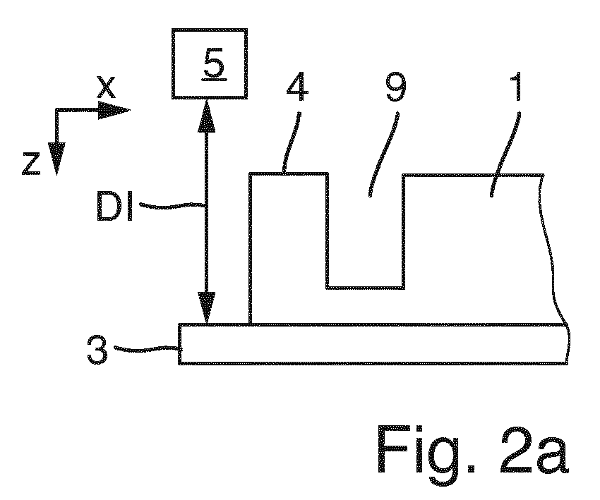
- Figs. 2a-d schematically depict an embodiment of step a) of the method according to the invention.
- a height profile HP of the rack 1 is measured by measuring a number of 4 vertical distances DI, Dl', DI" and DI'" between the distance sensing unit 5 on the one hand and the rack 1 and the rack placement unit 3 on the other hand in x-direction and y-direction.
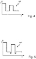
- the respective height profile HP of the rack 1 is schematically depicted in fig. 4 .
- the height profile HP of the rack 1 may be measured by measuring a greater number of vertical distances between the distance sensing unit 5 on the one hand and the rack 1 and the rack placement unit 3 on the other hand in x-direction and y-direction.
- the distance sensing unit 5 may be moved by a number of motors, in particular a number of linear motors, being adapted to move the distance sensing unit in x-direction and y-direction.
- the step a) comprises measuring a vertical distance DI between the distance sensing unit 5 and the rack placement unit 3, in particular close to a corner region 4 of the rack 1, (see fig. 2a ), a vertical distance DI' between the distance sensing unit 5 and a corner region 4 of the rack 1 (see fig. 2b ), a vertical distance DI" between the distance sensing unit 5 and a bottom of an orifice 9 of the rack 1 (see fig. 2c ) and a vertical distance DI'" between the distance sensing unit 5 and a top surface of the rack 1, in particular close to an orifice 9 of the rack 1 (see fig. 2d ).
- At least one corner region 4, in particular two corner regions 4, in particular two oppositely arranged corner regions 4, of the rack 1 is determined based on the measured height profile HP of the rack 1 (step b)).
- This step may be carried out by aligning or matching the measured height profile HP of the rack 1 with a height profile of the rack 1 being known from CAD (Computer-Aided Design) data of the rack 1 and with a height profile of the rack placement unit 3 being known from CAD (Computer-Aided Design) data of the rack placement unit 3.
- the position of the rack 1 on the rack placement unit 3 of the laboratory handling system 100 is determined based on the determined at least one corner region 4 of the rack 1 (step c)).
- Figs. 3a-d schematically depict a further embodiment of step a) of the method according to the invention.
- a height profile HP' of the rack 1 is measured by measuring a number of 6 vertical distances DI, DI', DI", DI"', DI"" and DI'”" between the distance sensing unit 5 on the one hand and the rack 1, the rack placement unit 3 and a number of laboratory sample container 2, which is inserted in the rack 1, on the other hand in x-direction and y-direction.
- the respective height profile HP' of the rack 1 is schematically depicted in fig. 5 .
- the height profile HP' of the rack 1 may be measured by measuring a greater number of vertical distances between the distance sensing unit 5 on the one hand and the rack 1, the rack placement unit 3 and a number of laboratory sample container 2, which is inserted in the rack 1, on the other hand in x-direction and y-direction.
- the distance sensing unit 5 may be moved by a number of motors, in particular a number of linear motors, being adapted to move the distance sensing unit in x-direction and y-direction.
- the step a) comprises measuring a vertical distance DI between the distance sensing unit 5 and the bottom of the rack placement unit 3, in particular close to a corner 4 of the rack 1, (see fig. 3a ), a vertical distance DI' between the distance sensing unit 5 and at least one corner region 4 of the rack 1 (see fig. 3b ), a vertical distance DI" between the distance sensing unit 5 and an upper end of a laboratory sample container 2 (see fig. 3c ), a vertical distance DI'" between the distance sensing unit 5 and a bottom of the laboratory sample container 2 (see fig. 3d ), a vertical distance DI"" between the distance sensing unit 5 and the upper end of the laboratory sample container 2 (see fig. 3e ) and a vertical distance DI”"' between the distance sensing unit 5 and a top surface of the rack 1, in particular close to the laboratory sample container 2 being inserted in a respective orifice 9 of the rack 1, (see fig. 3f ).
- At least one corner region 4, in particular two corner regions 4, in particular two oppositely arranged corner regions 4, of the rack 1 is determined based on the measured height profile HP' of the rack 1 (step b)).
- This step may be carried out by aligning or matching the measured height profile HP' of the rack 1 with a height profile of the rack 1 being known from CAD (Computer-Aided Design) data of the rack 1, with a height profile of the rack placement unit 3 being known from CAD (Computer-Aided Design) data of the rack placement unit 3 and with a height profile of the laboratory sample container 2 being known from CAD (Computer-Aided Design) data of the laboratory sample container 2.
- CAD Computer-Aided Design
- the position of the rack 1 on the rack placement unit 3 of the laboratory handling system 100 is determined based on the determined at least one corner region 4 of the rack 1 (step c)).
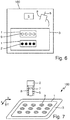
- Fig. 6 schematically depicts an embodiment of a laboratory handling system according to the invention.
- the laboratory handling system 100 comprises two racks 1. Each of the racks 1 is adapted to carry a number of laboratory sample containers 2. Further, each of the racks 1 has 4 orifices 9 for holding and/or carrying laboratory sample containers 2. Self-evidently, the laboratory handling system may comprise more than 2 racks 1, e.g. 3 to 1000 racks 1. Self-evidently, the racks 1 may have more than 4 orifices 9, e.g. 40 orifices 9. One of the two exemplary racks 1 carries laboratory sample containers 2 and the remaining exemplary rack 1 does not carry laboratory sample containers 2.
- the laboratory handling system 100 further comprises a rack placement unit 3.
- the two exemplary racks 1 are placed on the rack placement unit 3 of the laboratory handling system 100.
- the racks 1 are detachably held by the rack placement unit 3.
- the laboratory handling system 100 further comprises a distance sensing unit 5.
- the distance sensing unit 5 is adapted to sense a number of vertical distances between the distance sensing unit 5 and the rack 1 and/or the rack placement unit 3 and/or a number of laboratory sample containers 2, which is inserted in the rack 1, in x-direction and y-direction.
- the distance sensing unit 5 comprises or is in the form of a laser or 3D laser scanner.
- a laser or 3D laser scanner facilitates a high level of accuracy and error-proofness with respect to the measurement of the height profile of the rack 1.
- the laboratory handling system 100 further comprises a handling unit 6.
- the handling unit 6 is adapted to insert laboratory sample containers 2 in the racks 1 being placed on the rack placement unit 3 or remove laboratory sample containers 2 from the racks 1 being placed on the rack placement unit 3.
- the handling unit 6 has two gripping fingers 7, 8 being adapted to grip a laboratory sample container 2.
- Fig. 7 schematically depicts a further embodiment of a laboratory handling system 100 according to the invention.
- the laboratory handling system 100 comprises a rack 1 being adapted to carry a number of laboratory sample containers.
- the rack 1 has 12 orifices 9 for holding and/or carrying laboratory sample containers.
- the laboratory handling system 100 further comprises a rack placement unit 3.
- the rack 1 is placed on the rack placement unit 3 of the laboratory handling system 100. Further, the rack 1 is detachably held by the rack placement unit 3.
- the laboratory handling system 100 further comprises a distance sensing unit 5 being adapted to sense a number of vertical distances between the distance sensing unit 5 and the rack 1 and/or the rack placement unit 3 and/or a number of laboratory sample containers 2, which is inserted in the rack 1, in x-direction and y-direction.
- the distance sensing unit 5 is attached between two gripping fingers 7, 8, in particular to a connection or joint being adapted to facilitate a relative movement of two gripping fingers 7, 8, of the handling unit 6. Further, the distance sensing unit 5 may have the form of a tube.
- the invention proposes the use of a distance measurement device, in particular in the form of a laser or having a laser sensor.
- the distance measurement device may be placed at a gripper of a laboratory handling system or at a fixed position along the z-direction.
- An algorithm for determining the position of a rack being adapted to carry a number of laboratory sample containers and being placed on a placement unit of the laboratory handling system may be used.
- the algorithm may be divided into two main sub-algorithms.
- the first main sub-algorithm may be adapted to acquire data by making a 3D scan of the rack and the rack placement unit, in the following also denoted as workspace, by measuring the distance of the distance measurement device at each of the measurements points in the xy-plane (plane defined by the x-direction or x-axis and y-direction or y-axis).
- the amount of xy measurement points may be defined by a configurable resolution value (in mm or motor steps).
- the first sub-algorithm may follow the subsequent steps:
- the result/output data is a (x,y,z) point cloud and may be interpreted as a 3D mapping of the workspace where the x- and y-values may come from motor encoders and the z-value comes from the distance measurement at (x,y).
- the second main sub-algorithm may be adapted to process data, in particular to figure out the physical coordinates of all the rack positions.
- the second main sub-algorithm may be adapted to use the previous generated (x,y,z) point cloud to identify, for example, the first and last positions for the rack on the rack placement unit of the laboratory handling system.
- the coordinates of these two positions may be fed to a position computation algorithm.
- the algorithm may be simplified, for example, by using CAD information of the rack placement unit to estimate the position of the first and last rack position.
- data processing may be applied together with data acquisition to detect only the first rack position and its coordinates.
- the rack database may be used to estimate the position of the last rack position based on the recently measured first rack position.
- data processing may be applied together with data acquisition to detect only the last rack position and its coordinates.
Landscapes
- Engineering & Computer Science (AREA)
- Mechanical Engineering (AREA)
- Robotics (AREA)
- Chemical & Material Sciences (AREA)
- Physics & Mathematics (AREA)
- Health & Medical Sciences (AREA)
- General Health & Medical Sciences (AREA)
- Life Sciences & Earth Sciences (AREA)
- Analytical Chemistry (AREA)
- Biochemistry (AREA)
- General Physics & Mathematics (AREA)
- Immunology (AREA)
- Pathology (AREA)
- Clinical Laboratory Science (AREA)
- Chemical Kinetics & Catalysis (AREA)
- Optics & Photonics (AREA)
- Human Computer Interaction (AREA)
- Automatic Analysis And Handling Materials Therefor (AREA)
Abstract
a) measuring a height profile (HP, HP') of the rack (1),
b) determining at least one corner region (4) of the rack (1) based on the measured height profile (HP, HP') of the rack (1) and
c) determining the position of the rack (1) based on the determined at least one corner region (4) of the rack (1).


Description
- The invention relates to a method for determining a position of a rack on a rack placement unit of a laboratory handling system and to a laboratory handling system.
- Laboratory handling systems, in particular in the form of so-called in-sorters and out-sorters, are used in laboratory automation systems. The function of laboratory handling systems is the handling of laboratory sample containers comprising samples to be processed, e.g. by a laboratory station.
- The laboratory sample containers are often stored in racks, wherein a rack is adapted to store a certain number of laboratory sample containers. The number of laboratory sample containers to be stored depends on the type of the rack. Typically, the racks are placed on a rack placement unit of the laboratory handling system.
- A major problem concerns the determination of the position of a rack on the rack placement unit.
- It is an object of the invention to provide a method for determining a position of a rack on a rack placement unit of a laboratory handling system and a laboratory handling system having improved properties regarding the prior art.
- The invention solves this object by a method for determining a position of a rack on a rack placement unit of a laboratory handling system according to
claim 1 and by a laboratory handling system according to claim 13. Preferred embodiments are defined in the dependent claims. - The invention relates to a method for determining a position of a rack on a rack placement unit of a laboratory handling system, wherein the rack is adapted to carry or store a number of laboratory sample containers. The method comprises the following steps:
- a) measuring a height profile of the rack,
- b) determining at least one corner region of the rack based on the measured height profile of the rack and
- c) determining the position of the rack on the rack placement unit of the laboratory handling system based on the determined at least one corner region of the rack.
- The term "corner region" as used according to the present invention may define a region or area of the rack where two or more, in particular three, edges of the rack meet or a point (so-called corner point) of the rack where two or more, in particular three, edges of the rack meet.
- The term "height profile of the rack" as used according to the present invention may also be denoted as a vertical profile of the rack or as a profile of the rack in the z-direction or opposite to the z-direction.
- According to an embodiment, step a) comprises measuring a number of vertical distances between a distance sensing unit and the rack and/or the rack placement unit and/or a number of laboratory sample containers, which is inserted in the rack, in x-direction and y-direction. The distance sensing unit may be coupled to a number of motors, in particular a number of linear motors, being adapted to move the distance sensing unit in x-direction and y-direction. The number of vertical distances being measured between the distance sensing unit and the rack and/or the rack placement unit and/or the number of laboratory sample containers, which is inserted in the rack, in x-direction and y-direction may be defined by a configurable resolution value based on the motional freedom of the number of motors, in particular the number of linear motors, being adapted to move the distance sensing unit in x-direction and y-direction.
- According to an embodiment, the at least one corner region of the rack is determined based on the measured number of vertical distances between the distance sensing unit and the rack and/or the rack placement unit and/or the number of laboratory sample containers, which is inserted in the rack, in x-direction and y-direction.
- According to an embodiment, the distance sensing unit is assigned to a handling unit. The handling unit is adapted to insert laboratory sample containers in the rack or is adapted to remove laboratory sample containers from the rack based on the determined position of the rack. The handling unit may comprise two or more gripping fingers. The gripping fingers are adapted to grip a laboratory sample container. In particular, the handling unit is in the form of a gripper.
- According to an embodiment, the distance sensing unit is attached to the handling unit. In particular, the distance sensing unit is attached between two gripping fingers of the handling unit. For example, the distance sensing unit may be attached to a connection or joint, in particular solid body joint, between the two gripping fingers of the handling unit. The connection or joint is adapted to allow a relative movement between the two gripping fingers of the handling unit.
- According to an embodiment, the distance sensing unit is attached laterally to the handling unit, i.e. to an exterior or outer face of the handling unit. In particular, the distance sensing unit may not be attached between two gripping fingers of the handling unit.
- In principle, there is no limitation in respect of the form or shape of the distance sensing unit as long as the form or shape allows measuring a number of vertical distances between the distance sensing unit and the rack and/or the rack placement unit and/or a number of laboratory sample containers, which is inserted in the rack, in x-direction and y-direction. For example, the distance sensing unit may have a cylindrical, in particular circular cylindrical, i.e. tubular, form.
- According to an embodiment, the distance sensing unit comprises a laser or 3D laser scanner or is in the form of a laser or 3D laser scanner. A laser or 3D laser scanner facilitates a very accurate measurement of the height profile of the rack.
- According to an embodiment, step b) comprises determining the position of only one corner region of the rack based on the measured height profile of the rack.
- According to an embodiment, step b) comprises determining the position of two corner regions, in particular only two corner regions, of the rack based on the measured height profile of the rack.
- According to an embodiment, step b) comprises determining the position of two diametrically arranged corner regions of the rack based on the measured height profile of the rack.
- The embodiments described in the three preceding paragraphs have in particular the advantage that the determination of the position of the rack on the rack placement unit of the laboratory handling system can be additionally accelerated.
- According to an embodiment, step b) comprises aligning or matching the measured height profile of the rack with a height profile of the rack being known from CAD (Computer-Aided Design) data of the rack and/or with a height profile of the rack placement unit being known from CAD (Computer-Aided Design) data of the rack placement unit and/or with a height profile of a laboratory sample container being known from CAD (Computer-Aided Design) data of the laboratory sample container. Thus, the determination of the at least one corner region of the rack may be further accelerated.
- According to an embodiment, the rack comprises a number of orifices, wherein a respective orifice is adapted to receive a laboratory sample container, and the following step is performed: d) determining whether at least one of the number of orifices has received a laboratory sample container, i.e. is occupied by a laboratory sample container, or not based on the measured height profile of the rack. Thus, additional issues of the rack, such as the presence of a number of laboratory sample containers on the rack and/or the type of the number of laboratory sample containers on the rack and/or a correct placement of the number of laboratory sample containers on the rack, may be determined.
- The laboratory handling system is adapted to perform the above-described method.
- In particular, the laboratory handling system is adapted to handle a number of laboratory sample containers. A respective laboratory sample container is typically designed as a tube made of glass or transparent plastic and typically has an opening at an upper end. The laboratory sample container may be used to contain and/or store and/or transport a sample to be processed and/or analyzed, such as a blood sample, (blood) serum or plasma sample, urine sample, separation gel, cruor (blood cells) or a chemical sample. The laboratory sample container may be used to contain and/or store and/or transport any kind of biological liquid, for instance.
- According to an embodiment, the laboratory handling system comprises a number of racks. A respective rack is adapted to carry a number of laboratory sample containers. Reference is insofar made to the corresponding prior art. The number of racks may e.g. be a number in the range of 1 up to 1000. The number of laboratory sample containers carried by the respective rack may e.g. be a number in the range of 2 up to 150.
- According to an embodiment, the laboratory handling system further comprises a rack placement unit. At least one of the number of racks is placed on the rack placement unit. The rack placement unit may comprise a flat metal plate having rack holding elements. The rack holding elements may be adapted to detachably hold at least one of the number of racks being placed on the rack placement unit. The operating principle of racks which are detachably held by rack holding elements is e.g. disclosed in
DE 10 2008 058 755 A1 . - According to an embodiment, the laboratory handling system further comprises a distance sensing unit. The distance sensing unit is adapted to sense a number of vertical distances between the distance sensing unit and the rack and/or the rack placement unit and/or a number of laboratory sample containers, which is inserted in the rack, in x-direction and y-direction. In particular, the distance sensing unit comprises or is in the form of a laser or 3D laser scanner.
- According to an embodiment, the laboratory handling system further comprises a handling unit. The handling unit is adapted to insert laboratory sample containers in the rack being placed on the rack placement unit or to remove laboratory sample containers from the rack being placed on the rack placement unit. The handling unit may comprise two or more gripping fingers. In particular, the handling unit is in the form of a gripper.
- According to an embodiment, the distance sensing unit is assigned to the handling unit. In particular, the distance sensing unit may be attached to the handling unit, in particular between two gripping fingers of the handling unit. For example, the distance sensing unit may be attached to a connection or joint, in particular solid body joint, between the two gripping fingers of the handling unit. The connection or joint is adapted to allow a relative movement between the two gripping fingers of the handling unit. Alternatively, the distance sensing unit may be attached laterally to the handling unit.
- The laboratory handling system may further comprise a number of motors, in particular a number of linear motors, being adapted to move the distance sensing unit and/or the handling unit in x-direction and y-direction.
- The invention is in particular featured by the following advantages:
- The determination of a position of a rack on a rack placement unit of a laboratory handling system is achievable with a high level of accuracy.
- The determination of the position of the rack may be performed in a completely automated fashion. Thus, human interaction is dispensable and laboratory staff may carry out other activities while the inventive method is performed.
- The concurrent determination of two or more racks is possible without significant additional effort.
- Additional issues with respect to the rack may be determined, such as the presence and/or the type and/or the correct placement of laboratory sample containers being placed on the rack.
- The invention is hardware-independent and thus applicable in connection with any kind of laboratory handling system.
- The invention will now be described in detail with respect to the drawings schematically depicting embodiments of the invention. In detail:
- Fig. 1
- schematically depicts a laboratory sample container rack in a top view,
- Fig. 2 a-d
- schematically depict a first embodiment of step a) of the method according to the invention,
- Fig. 3 a-f
- schematically depict a second embodiment of step a) of the method according to the invention,
- Fig. 4
- schematically depicts the height profile measured according to the embodiment of step a) of the method according to the invention schematically depicted in
figs 2a-d , - Fig. 5
- schematically depicts the height profile measured according to the embodiment of step a) of the method according to the invention schematically depicted in
figs 3a-f , - Fig. 6
- schematically depicts an embodiment of a laboratory handling system according to the invention and
- Fig. 7
- schematically depicts a further embodiment of a laboratory handling system according to the invention.
-
Fig. 1 depicts a conventional laboratorysample container rack 1, i.e. arack 1 being adapted to carry a number oflaboratory sample containers 2, in a bottom view. The laboratorysample container rack 1 comprises a number of 20orifices 9, being adapted to receive conventionallaboratory sample containers 2, which may also be denoted as tubes, (see alsofig. 6 ). Therack 1 comprises fourcorner regions 4. -
Figs. 2a-d schematically depict an embodiment of step a) of the method according to the invention. - A height profile HP of the
rack 1 is measured by measuring a number of 4 vertical distances DI, Dl', DI" and DI'" between thedistance sensing unit 5 on the one hand and therack 1 and therack placement unit 3 on the other hand in x-direction and y-direction. The respective height profile HP of therack 1 is schematically depicted infig. 4 . - Self-evidently, the height profile HP of the
rack 1 may be measured by measuring a greater number of vertical distances between thedistance sensing unit 5 on the one hand and therack 1 and therack placement unit 3 on the other hand in x-direction and y-direction. - The
distance sensing unit 5 may be moved by a number of motors, in particular a number of linear motors, being adapted to move the distance sensing unit in x-direction and y-direction. - In detail, the step a) comprises measuring a vertical distance DI between the
distance sensing unit 5 and therack placement unit 3, in particular close to acorner region 4 of therack 1, (seefig. 2a ), a vertical distance DI' between thedistance sensing unit 5 and acorner region 4 of the rack 1 (seefig. 2b ), a vertical distance DI" between thedistance sensing unit 5 and a bottom of anorifice 9 of the rack 1 (seefig. 2c ) and a vertical distance DI'" between thedistance sensing unit 5 and a top surface of therack 1, in particular close to anorifice 9 of the rack 1 (seefig. 2d ). - Next, at least one
corner region 4, in particular twocorner regions 4, in particular two oppositely arrangedcorner regions 4, of therack 1 is determined based on the measured height profile HP of the rack 1 (step b)). This step may be carried out by aligning or matching the measured height profile HP of therack 1 with a height profile of therack 1 being known from CAD (Computer-Aided Design) data of therack 1 and with a height profile of therack placement unit 3 being known from CAD (Computer-Aided Design) data of therack placement unit 3. - Next, the position of the
rack 1 on therack placement unit 3 of thelaboratory handling system 100 is determined based on the determined at least onecorner region 4 of the rack 1 (step c)). -
Figs. 3a-d schematically depict a further embodiment of step a) of the method according to the invention. - A height profile HP' of the
rack 1 is measured by measuring a number of 6 vertical distances DI, DI', DI", DI"', DI"" and DI'"" between thedistance sensing unit 5 on the one hand and therack 1, therack placement unit 3 and a number oflaboratory sample container 2, which is inserted in therack 1, on the other hand in x-direction and y-direction. The respective height profile HP' of therack 1 is schematically depicted infig. 5 . - Self-evidently, the height profile HP' of the
rack 1 may be measured by measuring a greater number of vertical distances between thedistance sensing unit 5 on the one hand and therack 1, therack placement unit 3 and a number oflaboratory sample container 2, which is inserted in therack 1, on the other hand in x-direction and y-direction. - The
distance sensing unit 5 may be moved by a number of motors, in particular a number of linear motors, being adapted to move the distance sensing unit in x-direction and y-direction. - In detail, the step a) comprises measuring a vertical distance DI between the
distance sensing unit 5 and the bottom of therack placement unit 3, in particular close to acorner 4 of therack 1, (seefig. 3a ), a vertical distance DI' between thedistance sensing unit 5 and at least onecorner region 4 of the rack 1 (seefig. 3b ), a vertical distance DI" between thedistance sensing unit 5 and an upper end of a laboratory sample container 2 (seefig. 3c ), a vertical distance DI'" between thedistance sensing unit 5 and a bottom of the laboratory sample container 2 (seefig. 3d ), a vertical distance DI"" between thedistance sensing unit 5 and the upper end of the laboratory sample container 2 (seefig. 3e ) and a vertical distance DI""' between thedistance sensing unit 5 and a top surface of therack 1, in particular close to thelaboratory sample container 2 being inserted in arespective orifice 9 of therack 1, (seefig. 3f ). - Next, at least one
corner region 4, in particular twocorner regions 4, in particular two oppositely arrangedcorner regions 4, of therack 1 is determined based on the measured height profile HP' of the rack 1 (step b)). This step may be carried out by aligning or matching the measured height profile HP' of therack 1 with a height profile of therack 1 being known from CAD (Computer-Aided Design) data of therack 1, with a height profile of therack placement unit 3 being known from CAD (Computer-Aided Design) data of therack placement unit 3 and with a height profile of thelaboratory sample container 2 being known from CAD (Computer-Aided Design) data of thelaboratory sample container 2. - Next, the position of the
rack 1 on therack placement unit 3 of thelaboratory handling system 100 is determined based on the determined at least onecorner region 4 of the rack 1 (step c)). -
Fig. 6 schematically depicts an embodiment of a laboratory handling system according to the invention. - The
laboratory handling system 100 comprises tworacks 1. Each of theracks 1 is adapted to carry a number oflaboratory sample containers 2. Further, each of theracks 1 has 4orifices 9 for holding and/or carryinglaboratory sample containers 2. Self-evidently, the laboratory handling system may comprise more than 2racks 1, e.g. 3 to 1000racks 1. Self-evidently, theracks 1 may have more than 4orifices 9, e.g. 40orifices 9. One of the twoexemplary racks 1 carrieslaboratory sample containers 2 and the remainingexemplary rack 1 does not carrylaboratory sample containers 2. - The
laboratory handling system 100 further comprises arack placement unit 3. The twoexemplary racks 1 are placed on therack placement unit 3 of thelaboratory handling system 100. Theracks 1 are detachably held by therack placement unit 3. - The
laboratory handling system 100 further comprises adistance sensing unit 5. Thedistance sensing unit 5 is adapted to sense a number of vertical distances between thedistance sensing unit 5 and therack 1 and/or therack placement unit 3 and/or a number oflaboratory sample containers 2, which is inserted in therack 1, in x-direction and y-direction. In particular, thedistance sensing unit 5 comprises or is in the form of a laser or 3D laser scanner. A laser or 3D laser scanner facilitates a high level of accuracy and error-proofness with respect to the measurement of the height profile of therack 1. - The
laboratory handling system 100 further comprises ahandling unit 6. Thehandling unit 6 is adapted to insertlaboratory sample containers 2 in theracks 1 being placed on therack placement unit 3 or removelaboratory sample containers 2 from theracks 1 being placed on therack placement unit 3. Thehandling unit 6 has twogripping fingers laboratory sample container 2. -
Fig. 7 schematically depicts a further embodiment of alaboratory handling system 100 according to the invention. - The
laboratory handling system 100 comprises arack 1 being adapted to carry a number of laboratory sample containers. Therack 1 has 12orifices 9 for holding and/or carrying laboratory sample containers. - The
laboratory handling system 100 further comprises arack placement unit 3. Therack 1 is placed on therack placement unit 3 of thelaboratory handling system 100. Further, therack 1 is detachably held by therack placement unit 3. - The
laboratory handling system 100 further comprises adistance sensing unit 5 being adapted to sense a number of vertical distances between thedistance sensing unit 5 and therack 1 and/or therack placement unit 3 and/or a number oflaboratory sample containers 2, which is inserted in therack 1, in x-direction and y-direction. Thedistance sensing unit 5 is attached between twogripping fingers gripping fingers handling unit 6. Further, thedistance sensing unit 5 may have the form of a tube. - With respect to further features and advantages of the
laboratory handling system 100, reference is made in its entirety to the description offig. 6 . - According to a further aspect, the invention may be described as follows:
The invention proposes the use of a distance measurement device, in particular in the form of a laser or having a laser sensor. The distance measurement device may be placed at a gripper of a laboratory handling system or at a fixed position along the z-direction. An algorithm for determining the position of a rack being adapted to carry a number of laboratory sample containers and being placed on a placement unit of the laboratory handling system may be used. The algorithm may be divided into two main sub-algorithms. The first main sub-algorithm may be adapted to acquire data by making a 3D scan of the rack and the rack placement unit, in the following also denoted as workspace, by measuring the distance of the distance measurement device at each of the measurements points in the xy-plane (plane defined by the x-direction or x-axis and y-direction or y-axis). The amount of xy measurement points may be defined by a configurable resolution value (in mm or motor steps). For example, the first sub-algorithm may follow the subsequent steps: - 1. Go to a first x position to start the measurement (not necessarily origin position).
- 2. Go to a first y position to start the measurement (not necessarily origin position).
- 2.1. Take a depth measurement (e.g. using a laser sensor), save the value in memory together with the (x,y) coordinates where the measurement was taken.
- 2.2. Move y axis resolution (mm).
- 2.3. Go back to 2.1 until measurement range in y is covered.
- 3. Move x axis resolution (mm).
- 4. Go back to 2.1 until measurement range in x is covered.
- The result/output data is a (x,y,z) point cloud and may be interpreted as a 3D mapping of the workspace where the x- and y-values may come from motor encoders and the z-value comes from the distance measurement at (x,y).
- The second main sub-algorithm may be adapted to process data, in particular to figure out the physical coordinates of all the rack positions. In detail, the second main sub-algorithm may be adapted to use the previous generated (x,y,z) point cloud to identify, for example, the first and last positions for the rack on the rack placement unit of the laboratory handling system. The coordinates of these two positions may be fed to a position computation algorithm. The algorithm may be simplified, for example, by using CAD information of the rack placement unit to estimate the position of the first and last rack position. Alternatively, data processing may be applied together with data acquisition to detect only the first rack position and its coordinates. Further, the rack database may be used to estimate the position of the last rack position based on the recently measured first rack position. Alternatively, data processing may be applied together with data acquisition to detect only the last rack position and its coordinates.
Claims (15)
- Method for determining a position of a rack (1) on a rack placement unit (3) of a laboratory handling system (100), wherein the rack (1) is adapted to carry a number of laboratory sample containers (2), the method comprising the steps:a) measuring a height profile (HP, HP') of the rack (1),b) determining at least one corner region (4) of the rack (1) based on the measured height profile (HP, HP') of the rack (1) andc) determining the position of the rack (1) based on the determined at least one corner region (4) of the rack (1).
- Method according to claim 1, characterized in that- step a) comprises measuring a number of vertical distances (DI, DI', DI", DI"', DI"", DI""') between a distance sensing unit (5) and the rack (1) and/or rack placement unit (3) and/or a number of laboratory sample containers (2), which is inserted in the rack (1), in x-direction and y-direction.
- Method according to claim 2, characterized in that- the at least one corner region (4) of the rack (1) is determined based on the measured number of vertical distances (DI, DI', DI", DI"', DI"", DI'"") between the distance sensing unit (5) and the rack (1) and/or rack placement unit (3) and/or the number of laboratory sample containers (2), which is inserted in the rack (1), in x-direction and y-direction.
- Method according to claim 2 or 3, characterized in that- the distance sensing unit (5) is assigned to a handling unit (6), wherein the handling unit (6) is adapted to insert laboratory sample containers (2) in the rack (1) or remove laboratory sample containers (2) from the rack (1) based on the determined position of the rack (1).
- Method according to any of the claims 2 to 4, characterized in that- the distance sensing unit (5) is attached between two gripping fingers (7, 8) of the handling unit (6).
- Method according to any of the claims 2 to 4, characterized in that- the distance sensing unit (5) is attached laterally to the handling unit (6).
- Method according to any of the claims 2 to 6, characterized in that- the distance sensing unit (5) comprises or is in the form of a laser or 3D laser scanner.
- Method according to any of the preceding claims, characterized in that- step b) comprises determining the position of only one corner region (4) of the rack (1) based on the measured height profile (HP, HP') of the rack (1).
- Method according to any of the claims 1 to 7, characterized in that- step b) comprises determining the position of two corner regions (4) of the rack (1) based on the measured height profile (HP, HP') of the rack (1).
- Method according to any of the claims 1 to 7 or 9, characterized in that- step b) comprises determining the position of two diametrically arranged corner regions (4) of the rack based on the measured height profile (HP, HP') of the rack (1).
- Method according to any of the preceding claims, characterized in that- step b) comprises matching the measured height profile (HP, HP') of the rack (1) with a height profile of the rack (1) being known from CAD data of the rack (1) and/or with a height profile of the rack placement unit (3) being known from CAD data of the rack placement unit (3) and/or with a height profile of a laboratory sample container (2) being known from CAD data of the laboratory sample container (2).
- Method according to any of the preceding claims, characterized in that- the rack (1) comprises a number of orifices (9), wherein a respective orifice (9) is adapted to receive a laboratory sample container (2), and the following step is performed:
d) determining, whether at least one of the number of orifices (9) is occupied by a laboratory sample container (2) or not based on the measured height profile (HP, HP') of the rack (1). - Laboratory handling system (100), characterized in that- the laboratory handling system (100) is adapted to perform the method according to any of the preceding claims.
- Laboratory handling system (100) according to claim 13,
characterized in that the laboratory handling system (100) comprises- a number of racks (1), wherein a respective rack (1) is adapted to carry a number of laboratory sample containers (2),- a rack placement unit (3), wherein at least one of the number of racks (1) is placed on the rack placement unit (3), and- a distance sensing unit (5) being adapted to sense a number of vertical distances (DI, DI', DI", DI"', DI"", DI""') between the distance sensing unit (5) and the rack (1) and/or rack placement unit (3) in x-direction and y-direction. - Laboratory handling system (100) according to claim 13 or 14, further comprising- a handling unit (6), wherein the handling unit (6) is adapted to insert laboratory sample containers (2) in the rack (1) being placed on the rack placement unit (3) or remove laboratory sample containers (2) from the rack (1) being placed on the rack placement unit (3) and the distance sensing unit (5) is assigned to the handling unit (6).
Priority Applications (4)
| Application Number | Priority Date | Filing Date | Title |
|---|---|---|---|
| EP19195576.4A EP3789772B1 (en) | 2019-09-05 | 2019-09-05 | Method for determining a position of a rack on a rack placement unit of a laboratory handling system and laboratory handling system |
| CN202010895032.8A CN112441361B (en) | 2019-09-05 | 2020-08-31 | Method and laboratory manipulation system for determining the position of a shelf on a shelf placement unit |
| US17/008,795 US12053874B2 (en) | 2019-09-05 | 2020-09-01 | Method for determining a position of a rack on a rack placement unit of a laboratory handling system and laboratory handling system |
| JP2020147819A JP7000519B2 (en) | 2019-09-05 | 2020-09-02 | How to determine the position of the rack on the rack placement unit of the laboratory operating system and the laboratory operating system |
Applications Claiming Priority (1)
| Application Number | Priority Date | Filing Date | Title |
|---|---|---|---|
| EP19195576.4A EP3789772B1 (en) | 2019-09-05 | 2019-09-05 | Method for determining a position of a rack on a rack placement unit of a laboratory handling system and laboratory handling system |
Publications (2)
| Publication Number | Publication Date |
|---|---|
| EP3789772A1 true EP3789772A1 (en) | 2021-03-10 |
| EP3789772B1 EP3789772B1 (en) | 2025-03-26 |
Family
ID=67874318
Family Applications (1)
| Application Number | Title | Priority Date | Filing Date |
|---|---|---|---|
| EP19195576.4A Active EP3789772B1 (en) | 2019-09-05 | 2019-09-05 | Method for determining a position of a rack on a rack placement unit of a laboratory handling system and laboratory handling system |
Country Status (4)
| Country | Link |
|---|---|
| US (1) | US12053874B2 (en) |
| EP (1) | EP3789772B1 (en) |
| JP (1) | JP7000519B2 (en) |
| CN (1) | CN112441361B (en) |
Families Citing this family (1)
| Publication number | Priority date | Publication date | Assignee | Title |
|---|---|---|---|---|
| EP4361638A1 (en) * | 2022-10-27 | 2024-05-01 | Beckman Coulter, Inc. | Device, system and method for handling sample containers |
Citations (3)
| Publication number | Priority date | Publication date | Assignee | Title |
|---|---|---|---|---|
| DE102008058755A1 (en) | 2008-11-14 | 2010-05-27 | Pvt Probenverteiltechnik Gmbh | Rack device for a sample distribution system |
| US20110039709A1 (en) * | 2007-08-20 | 2011-02-17 | Qiagen Gmbh | Apparatus for processing biological material |
| EP3444616A1 (en) * | 2017-08-18 | 2019-02-20 | Roche Diagnostics GmbH | Method for determining, whether an opening of a laboratory sample container is open or closed, laboratory device and laboratory automation system |
Family Cites Families (14)
| Publication number | Priority date | Publication date | Assignee | Title |
|---|---|---|---|---|
| JP3239277B2 (en) * | 1992-07-15 | 2001-12-17 | 富士通株式会社 | Intelligent robot |
| US20050158212A1 (en) * | 2004-01-15 | 2005-07-21 | Michael Yavilevich | Automated laboratory system and analytical module |
| CA2658533C (en) | 2006-07-28 | 2016-03-15 | Qiagen Gmbh | Device for processing samples |
| JP2009180607A (en) | 2008-01-30 | 2009-08-13 | Olympus Corp | Automatic analyzer |
| US8111390B2 (en) * | 2009-04-17 | 2012-02-07 | Applied Materials, Inc. | Method and apparatus for residue detection in the edge deleted area of a substrate |
| JP5736128B2 (en) | 2010-06-25 | 2015-06-17 | シスメックス株式会社 | Sample processing system, rack transport system, sample processing method, and rack transport method |
| CN103403445B (en) | 2011-03-03 | 2016-09-14 | 皇家飞利浦有限公司 | Light-emitting device with spring-loaded LED keeper |
| US9046506B2 (en) | 2011-11-07 | 2015-06-02 | Beckman Coulter, Inc. | Specimen container detection |
| EP2620775B1 (en) * | 2012-01-27 | 2015-05-27 | GLP systems GmbH | Holder cartridge |
| EP2631201B1 (en) | 2012-02-22 | 2014-06-18 | CareFusion Germany 326 GmbH | Method for determining when medicine packages are positioned incorrectly |
| CA2950296C (en) * | 2014-06-10 | 2022-12-13 | Siemens Healthcare Diagnostics Inc. | Drawer vision system |
| EP3109642B1 (en) * | 2015-06-25 | 2024-04-10 | Roche Diagnostics GmbH | Device and method for handling racks of disposable pipette tips in a laboratory automation system and laboratory automation system |
| DE102016205469A1 (en) * | 2016-04-01 | 2017-10-05 | Wobben Properties Gmbh | Measuring system for measuring a surface |
| US11975330B2 (en) * | 2017-01-31 | 2024-05-07 | Myriad Women's Health, Inc. | Devices for handling laboratory plates and methods of using the same |
-
2019
- 2019-09-05 EP EP19195576.4A patent/EP3789772B1/en active Active
-
2020
- 2020-08-31 CN CN202010895032.8A patent/CN112441361B/en active Active
- 2020-09-01 US US17/008,795 patent/US12053874B2/en active Active
- 2020-09-02 JP JP2020147819A patent/JP7000519B2/en active Active
Patent Citations (3)
| Publication number | Priority date | Publication date | Assignee | Title |
|---|---|---|---|---|
| US20110039709A1 (en) * | 2007-08-20 | 2011-02-17 | Qiagen Gmbh | Apparatus for processing biological material |
| DE102008058755A1 (en) | 2008-11-14 | 2010-05-27 | Pvt Probenverteiltechnik Gmbh | Rack device for a sample distribution system |
| EP3444616A1 (en) * | 2017-08-18 | 2019-02-20 | Roche Diagnostics GmbH | Method for determining, whether an opening of a laboratory sample container is open or closed, laboratory device and laboratory automation system |
Also Published As
| Publication number | Publication date |
|---|---|
| CN112441361B (en) | 2023-01-13 |
| EP3789772B1 (en) | 2025-03-26 |
| JP7000519B2 (en) | 2022-01-19 |
| US12053874B2 (en) | 2024-08-06 |
| CN112441361A (en) | 2021-03-05 |
| JP2021043197A (en) | 2021-03-18 |
| US20210069912A1 (en) | 2021-03-11 |
Similar Documents
| Publication | Publication Date | Title |
|---|---|---|
| EP2658958B1 (en) | Methods and systems for calibration of a positional orientation between a sample container and nozzle tip | |
| JP7846643B2 (en) | Laboratory System | |
| EP2643701B1 (en) | Devices and methods for programmable manipulation of pipettes | |
| US10946372B2 (en) | Method for determining the position of a robotic arm in a liquid handling system, and a corresponding liquid handling system | |
| EP2042274B1 (en) | Method for aligning the position of a movable arm | |
| US10145857B2 (en) | Tube tray vision system | |
| US7264432B2 (en) | Device and method for transferring objects | |
| JP5615705B2 (en) | Method for determining the stacked number of stacked receiving devices | |
| AU2019226329A1 (en) | Measuring apparatus for a laboratory appliance for measuring an article, article for said measuring apparatus and measuring method | |
| US20150276779A1 (en) | System and method for the automated processing of fluids, method for determining the matching of objects | |
| EP3789772B1 (en) | Method for determining a position of a rack on a rack placement unit of a laboratory handling system and laboratory handling system | |
| WO2022040598A1 (en) | Systems and methods for framing workspaces of robotic fluid handling systems | |
| JP6529974B2 (en) | How to determine the position of at least one mapping token | |
| CN116423389A (en) | A Method for Determining the Workpiece Coordinate System for Robot Optical Component Polishing | |
| US20100226825A1 (en) | Smart pipette with sensor in tip | |
| CN119657253A (en) | Positioning pipette tips with guide frames | |
| CN105277731A (en) | Positioning method of sampling system and in vitro diagnostic device with application of positioning method | |
| JP2023019081A (en) | Cell manipulation system, program, and cell manipulation method | |
| US20240293929A1 (en) | Apparatus and method for automated teaching of locations in laboratory automation equipment | |
| CN119199169A (en) | Automatic detection method, system and medium of fully automatic drug detection instrument | |
| WO2025226511A1 (en) | Systems and methods for using different types of sample container carriers in diagnostic laboratory systems | |
| CN118023365A (en) | Bending center debugging method and system |
Legal Events
| Date | Code | Title | Description |
|---|---|---|---|
| PUAI | Public reference made under article 153(3) epc to a published international application that has entered the european phase |
Free format text: ORIGINAL CODE: 0009012 |
|
| STAA | Information on the status of an ep patent application or granted ep patent |
Free format text: STATUS: THE APPLICATION HAS BEEN PUBLISHED |
|
| AK | Designated contracting states |
Kind code of ref document: A1 Designated state(s): AL AT BE BG CH CY CZ DE DK EE ES FI FR GB GR HR HU IE IS IT LI LT LU LV MC MK MT NL NO PL PT RO RS SE SI SK SM TR |
|
| AX | Request for extension of the european patent |
Extension state: BA ME |
|
| STAA | Information on the status of an ep patent application or granted ep patent |
Free format text: STATUS: REQUEST FOR EXAMINATION WAS MADE |
|
| 17P | Request for examination filed |
Effective date: 20210909 |
|
| RBV | Designated contracting states (corrected) |
Designated state(s): AL AT BE BG CH CY CZ DE DK EE ES FI FR GB GR HR HU IE IS IT LI LT LU LV MC MK MT NL NO PL PT RO RS SE SI SK SM TR |
|
| STAA | Information on the status of an ep patent application or granted ep patent |
Free format text: STATUS: EXAMINATION IS IN PROGRESS |
|
| 17Q | First examination report despatched |
Effective date: 20220818 |
|
| GRAP | Despatch of communication of intention to grant a patent |
Free format text: ORIGINAL CODE: EPIDOSNIGR1 |
|
| STAA | Information on the status of an ep patent application or granted ep patent |
Free format text: STATUS: GRANT OF PATENT IS INTENDED |
|
| INTG | Intention to grant announced |
Effective date: 20240826 |
|
| GRAJ | Information related to disapproval of communication of intention to grant by the applicant or resumption of examination proceedings by the epo deleted |
Free format text: ORIGINAL CODE: EPIDOSDIGR1 |
|
| STAA | Information on the status of an ep patent application or granted ep patent |
Free format text: STATUS: EXAMINATION IS IN PROGRESS |
|
| GRAP | Despatch of communication of intention to grant a patent |
Free format text: ORIGINAL CODE: EPIDOSNIGR1 |
|
| STAA | Information on the status of an ep patent application or granted ep patent |
Free format text: STATUS: GRANT OF PATENT IS INTENDED |
|
| INTC | Intention to grant announced (deleted) | ||
| INTG | Intention to grant announced |
Effective date: 20241202 |
|
| GRAS | Grant fee paid |
Free format text: ORIGINAL CODE: EPIDOSNIGR3 |
|
| GRAA | (expected) grant |
Free format text: ORIGINAL CODE: 0009210 |
|
| STAA | Information on the status of an ep patent application or granted ep patent |
Free format text: STATUS: THE PATENT HAS BEEN GRANTED |
|
| AK | Designated contracting states |
Kind code of ref document: B1 Designated state(s): AL AT BE BG CH CY CZ DE DK EE ES FI FR GB GR HR HU IE IS IT LI LT LU LV MC MK MT NL NO PL PT RO RS SE SI SK SM TR |
|
| REG | Reference to a national code |
Ref country code: GB Ref legal event code: FG4D |
|
| REG | Reference to a national code |
Ref country code: CH Ref legal event code: EP |
|
| REG | Reference to a national code |
Ref country code: IE Ref legal event code: FG4D |
|
| REG | Reference to a national code |
Ref country code: DE Ref legal event code: R096 Ref document number: 602019067692 Country of ref document: DE |
|
| PG25 | Lapsed in a contracting state [announced via postgrant information from national office to epo] |
Ref country code: RS Free format text: LAPSE BECAUSE OF FAILURE TO SUBMIT A TRANSLATION OF THE DESCRIPTION OR TO PAY THE FEE WITHIN THE PRESCRIBED TIME-LIMIT Effective date: 20250626 |
|
| PG25 | Lapsed in a contracting state [announced via postgrant information from national office to epo] |
Ref country code: FI Free format text: LAPSE BECAUSE OF FAILURE TO SUBMIT A TRANSLATION OF THE DESCRIPTION OR TO PAY THE FEE WITHIN THE PRESCRIBED TIME-LIMIT Effective date: 20250326 |
|
| REG | Reference to a national code |
Ref country code: LT Ref legal event code: MG9D |
|
| PG25 | Lapsed in a contracting state [announced via postgrant information from national office to epo] |
Ref country code: NO Free format text: LAPSE BECAUSE OF FAILURE TO SUBMIT A TRANSLATION OF THE DESCRIPTION OR TO PAY THE FEE WITHIN THE PRESCRIBED TIME-LIMIT Effective date: 20250626 |
|
| PG25 | Lapsed in a contracting state [announced via postgrant information from national office to epo] |
Ref country code: HR Free format text: LAPSE BECAUSE OF FAILURE TO SUBMIT A TRANSLATION OF THE DESCRIPTION OR TO PAY THE FEE WITHIN THE PRESCRIBED TIME-LIMIT Effective date: 20250326 |
|
| PG25 | Lapsed in a contracting state [announced via postgrant information from national office to epo] |
Ref country code: LV Free format text: LAPSE BECAUSE OF FAILURE TO SUBMIT A TRANSLATION OF THE DESCRIPTION OR TO PAY THE FEE WITHIN THE PRESCRIBED TIME-LIMIT Effective date: 20250326 |
|
| PG25 | Lapsed in a contracting state [announced via postgrant information from national office to epo] |
Ref country code: GR Free format text: LAPSE BECAUSE OF FAILURE TO SUBMIT A TRANSLATION OF THE DESCRIPTION OR TO PAY THE FEE WITHIN THE PRESCRIBED TIME-LIMIT Effective date: 20250627 Ref country code: BG Free format text: LAPSE BECAUSE OF FAILURE TO SUBMIT A TRANSLATION OF THE DESCRIPTION OR TO PAY THE FEE WITHIN THE PRESCRIBED TIME-LIMIT Effective date: 20250326 |
|
| REG | Reference to a national code |
Ref country code: NL Ref legal event code: MP Effective date: 20250326 |
|
| PG25 | Lapsed in a contracting state [announced via postgrant information from national office to epo] |
Ref country code: NL Free format text: LAPSE BECAUSE OF FAILURE TO SUBMIT A TRANSLATION OF THE DESCRIPTION OR TO PAY THE FEE WITHIN THE PRESCRIBED TIME-LIMIT Effective date: 20250326 |
|
| PG25 | Lapsed in a contracting state [announced via postgrant information from national office to epo] |
Ref country code: SE Free format text: LAPSE BECAUSE OF FAILURE TO SUBMIT A TRANSLATION OF THE DESCRIPTION OR TO PAY THE FEE WITHIN THE PRESCRIBED TIME-LIMIT Effective date: 20250326 |
|
| REG | Reference to a national code |
Ref country code: AT Ref legal event code: MK05 Ref document number: 1779428 Country of ref document: AT Kind code of ref document: T Effective date: 20250326 |
|
| PG25 | Lapsed in a contracting state [announced via postgrant information from national office to epo] |
Ref country code: SM Free format text: LAPSE BECAUSE OF FAILURE TO SUBMIT A TRANSLATION OF THE DESCRIPTION OR TO PAY THE FEE WITHIN THE PRESCRIBED TIME-LIMIT Effective date: 20250326 |
|
| PG25 | Lapsed in a contracting state [announced via postgrant information from national office to epo] |
Ref country code: ES Free format text: LAPSE BECAUSE OF FAILURE TO SUBMIT A TRANSLATION OF THE DESCRIPTION OR TO PAY THE FEE WITHIN THE PRESCRIBED TIME-LIMIT Effective date: 20250326 Ref country code: PT Free format text: LAPSE BECAUSE OF FAILURE TO SUBMIT A TRANSLATION OF THE DESCRIPTION OR TO PAY THE FEE WITHIN THE PRESCRIBED TIME-LIMIT Effective date: 20250728 |
|
| PGFP | Annual fee paid to national office [announced via postgrant information from national office to epo] |
Ref country code: DE Payment date: 20250820 Year of fee payment: 7 |
|
| PG25 | Lapsed in a contracting state [announced via postgrant information from national office to epo] |
Ref country code: IT Free format text: LAPSE BECAUSE OF FAILURE TO SUBMIT A TRANSLATION OF THE DESCRIPTION OR TO PAY THE FEE WITHIN THE PRESCRIBED TIME-LIMIT Effective date: 20250326 Ref country code: PL Free format text: LAPSE BECAUSE OF FAILURE TO SUBMIT A TRANSLATION OF THE DESCRIPTION OR TO PAY THE FEE WITHIN THE PRESCRIBED TIME-LIMIT Effective date: 20250326 |
|
| PGFP | Annual fee paid to national office [announced via postgrant information from national office to epo] |
Ref country code: GB Payment date: 20250822 Year of fee payment: 7 |
|
| PG25 | Lapsed in a contracting state [announced via postgrant information from national office to epo] |
Ref country code: AT Free format text: LAPSE BECAUSE OF FAILURE TO SUBMIT A TRANSLATION OF THE DESCRIPTION OR TO PAY THE FEE WITHIN THE PRESCRIBED TIME-LIMIT Effective date: 20250326 |
|
| PGFP | Annual fee paid to national office [announced via postgrant information from national office to epo] |
Ref country code: FR Payment date: 20250820 Year of fee payment: 7 |
|
| PG25 | Lapsed in a contracting state [announced via postgrant information from national office to epo] |
Ref country code: EE Free format text: LAPSE BECAUSE OF FAILURE TO SUBMIT A TRANSLATION OF THE DESCRIPTION OR TO PAY THE FEE WITHIN THE PRESCRIBED TIME-LIMIT Effective date: 20250326 |
|
| PG25 | Lapsed in a contracting state [announced via postgrant information from national office to epo] |
Ref country code: RO Free format text: LAPSE BECAUSE OF FAILURE TO SUBMIT A TRANSLATION OF THE DESCRIPTION OR TO PAY THE FEE WITHIN THE PRESCRIBED TIME-LIMIT Effective date: 20250326 |
|
| PG25 | Lapsed in a contracting state [announced via postgrant information from national office to epo] |
Ref country code: SK Free format text: LAPSE BECAUSE OF FAILURE TO SUBMIT A TRANSLATION OF THE DESCRIPTION OR TO PAY THE FEE WITHIN THE PRESCRIBED TIME-LIMIT Effective date: 20250326 |
|
| PG25 | Lapsed in a contracting state [announced via postgrant information from national office to epo] |
Ref country code: IS Free format text: LAPSE BECAUSE OF FAILURE TO SUBMIT A TRANSLATION OF THE DESCRIPTION OR TO PAY THE FEE WITHIN THE PRESCRIBED TIME-LIMIT Effective date: 20250726 |
|
| REG | Reference to a national code |
Ref country code: DE Ref legal event code: R097 Ref document number: 602019067692 Country of ref document: DE |
|
| PG25 | Lapsed in a contracting state [announced via postgrant information from national office to epo] |
Ref country code: DK Free format text: LAPSE BECAUSE OF FAILURE TO SUBMIT A TRANSLATION OF THE DESCRIPTION OR TO PAY THE FEE WITHIN THE PRESCRIBED TIME-LIMIT Effective date: 20250326 |
|
| PG25 | Lapsed in a contracting state [announced via postgrant information from national office to epo] |
Ref country code: CZ Free format text: LAPSE BECAUSE OF FAILURE TO SUBMIT A TRANSLATION OF THE DESCRIPTION OR TO PAY THE FEE WITHIN THE PRESCRIBED TIME-LIMIT Effective date: 20250326 |
|
| PLBE | No opposition filed within time limit |
Free format text: ORIGINAL CODE: 0009261 |
|
| STAA | Information on the status of an ep patent application or granted ep patent |
Free format text: STATUS: NO OPPOSITION FILED WITHIN TIME LIMIT |
|
| REG | Reference to a national code |
Ref country code: CH Ref legal event code: L10 Free format text: ST27 STATUS EVENT CODE: U-0-0-L10-L00 (AS PROVIDED BY THE NATIONAL OFFICE) Effective date: 20260211 |
|
| 26N | No opposition filed |
Effective date: 20260105 |
|
| REG | Reference to a national code |
Ref country code: CH Ref legal event code: H13 Free format text: ST27 STATUS EVENT CODE: U-0-0-H10-H13 (AS PROVIDED BY THE NATIONAL OFFICE) Effective date: 20260504 |