EP3789727B1 - Interferometric measuring device - Google Patents
Interferometric measuring device Download PDFInfo
- Publication number
- EP3789727B1 EP3789727B1 EP19195284.5A EP19195284A EP3789727B1 EP 3789727 B1 EP3789727 B1 EP 3789727B1 EP 19195284 A EP19195284 A EP 19195284A EP 3789727 B1 EP3789727 B1 EP 3789727B1
- Authority
- EP
- European Patent Office
- Prior art keywords
- optical
- compensator
- fiber
- reflector
- partial
- Prior art date
- Legal status (The legal status is an assumption and is not a legal conclusion. Google has not performed a legal analysis and makes no representation as to the accuracy of the status listed.)
- Active
Links
Images



Classifications
-
- G—PHYSICS
- G01—MEASURING; TESTING
- G01B—MEASURING LENGTH, THICKNESS OR SIMILAR LINEAR DIMENSIONS; MEASURING ANGLES; MEASURING AREAS; MEASURING IRREGULARITIES OF SURFACES OR CONTOURS
- G01B9/00—Measuring instruments characterised by the use of optical techniques
- G01B9/02—Interferometers
- G01B9/02015—Interferometers characterised by the beam path configuration
- G01B9/02027—Two or more interferometric channels or interferometers
-
- G—PHYSICS
- G01—MEASURING; TESTING
- G01B—MEASURING LENGTH, THICKNESS OR SIMILAR LINEAR DIMENSIONS; MEASURING ANGLES; MEASURING AREAS; MEASURING IRREGULARITIES OF SURFACES OR CONTOURS
- G01B9/00—Measuring instruments characterised by the use of optical techniques
- G01B9/02—Interferometers
- G01B9/02015—Interferometers characterised by the beam path configuration
- G01B9/02027—Two or more interferometric channels or interferometers
- G01B9/02028—Two or more reference or object arms in one interferometer
-
- G—PHYSICS
- G01—MEASURING; TESTING
- G01B—MEASURING LENGTH, THICKNESS OR SIMILAR LINEAR DIMENSIONS; MEASURING ANGLES; MEASURING AREAS; MEASURING IRREGULARITIES OF SURFACES OR CONTOURS
- G01B9/00—Measuring instruments characterised by the use of optical techniques
- G01B9/02—Interferometers
- G01B9/02055—Reduction or prevention of errors; Testing; Calibration
- G01B9/02062—Active error reduction, i.e. varying with time
- G01B9/02064—Active error reduction, i.e. varying with time by particular adjustment of coherence gate, i.e. adjusting position of zero path difference in low coherence interferometry
- G01B9/02065—Active error reduction, i.e. varying with time by particular adjustment of coherence gate, i.e. adjusting position of zero path difference in low coherence interferometry using a second interferometer before or after measuring interferometer
-
- G—PHYSICS
- G01—MEASURING; TESTING
- G01B—MEASURING LENGTH, THICKNESS OR SIMILAR LINEAR DIMENSIONS; MEASURING ANGLES; MEASURING AREAS; MEASURING IRREGULARITIES OF SURFACES OR CONTOURS
- G01B9/00—Measuring instruments characterised by the use of optical techniques
- G01B9/02—Interferometers
- G01B9/0209—Low-coherence interferometers
-
- G—PHYSICS
- G01—MEASURING; TESTING
- G01B—MEASURING LENGTH, THICKNESS OR SIMILAR LINEAR DIMENSIONS; MEASURING ANGLES; MEASURING AREAS; MEASURING IRREGULARITIES OF SURFACES OR CONTOURS
- G01B2290/00—Aspects of interferometers not specifically covered by any group under G01B9/02
- G01B2290/45—Multiple detectors for detecting interferometer signals
Definitions
- the present disclosure relates to the field of interferometric measuring devices, in particular to fiber-implemented interferometric measuring devices for measuring a surface, a distance or profile of an object by reflection of electromagnetic radiation from the surface.
- Document DE10 2008 033 942 B3 discloses a fiber optically implemented optical multi-wavelength sensor for quantitatively measuring of a distance and/or of a topology of a surface by making use of two or more lasers having a wavelength between 1520 nm and 1630 nm and comprising a sensor head that is periodically spatially modulated in the direction of a measurement beam.
- Laser light used for such a sensor is highly coherent, both in the spatial and temporal domain. This allows to implement a highly precise measuring at a comparatively large working distance between the surface of an object and the sensor.
- Such devices also measure in reflection mode.
- the laser light emitted by the sensor and directed towards and onto the surface is reflected by the surface and is captured again by the sensor.
- the light emitted by the sensor is focused on the surface and the surface of the object is scanned in one or two dimensions by a respective relative movement between the sensor and the surface.
- an object of the present disclosure to provide an improved interferometric measuring device for measuring a surface, a profile or topology of an object, in particular of a transparent object, such as an optical component, e.g. of a lens, wherein the interferometric measuring device is particularly suitable for measuring of objects having comparatively small dimensions along a measuring axis or measuring direction. It is a particular aim to provide an improved interferometric measuring device that provides a well-defined and tunable or adjustable measuring depth or measuring length along a measuring direction.
- the working distance of the interferometric measuring device should be easily adaptable and tunable to varying measuring demands and measuring configurations.
- the interferometric measuring device should be rather robust in construction and operation. It should be easily reconfigurable and adaptable to different measuring scenarios and measuring conditions.
- an interferometric measuring device for measuring a surface, a profile or topology of an object, in particular of a transparent object, such as an optical component, e.g. of a lens.
- the measuring device comprises a light source.
- the light source is configured to emit a measuring beam.
- the measuring beam comprises a coherence length L.
- the light source is of low temporal coherence and of comparatively high spatial coherence.
- the light source typically comprises a broadband light source, such as a superluminescent diode.
- the light source may also comprise an amplified spontaneous emitter (ASE) configured to generate a measuring beam produced by spontaneous emission that is optically amplified by the process of stimulated emission in a gain medium.
- the light source may comprise one or several superluminescent diodes or doped fiber amplifiers.
- the measuring device further comprises an optical probe comprising an internal reflector.
- the optical probe is coupled to the light source by a first fiber-based optical signal path.
- the measuring device further comprises a signal analyzer coupled to the optical probe by a second fiber-based optical signal path.
- the first and the second fiber-based optical signal paths may at least partially overlap. They may be implemented by one and the same optical or light transmitting component.
- the measuring device further comprises an optical compensator arranged in one of the first fiber-based optical signal path and the second fiber-based optical signal path.
- the optical compensator is either arranged in the first fiber-based optical signal path or in the second fiber-based optical signal path.
- One of the optical probe and the optical compensator is configured to split the measuring beam into a first partial beam and a second partial beam and to impose an optical path difference D onto a portion of one of the first partial beam and the second partial beam relative to a portion of the other one of the first partial beam and the second partial beam.
- the optical path difference D imposed by the optical probe or the optical compensator is larger than the coherence length L.
- the optical path difference D is larger than the temporal coherence length L.
- the other one of the optical probe and the optical compensator is configured to compensate the optical path difference.
- the first and second partial beam can no longer interfere and as first and second partial beams are recombined no interference pattern will be apparent on the signal analyzer. It is only and due to the other one of the optical probe and the optical compensator and due to the compensation of the optical path difference that light reflected from the internal reflector of the optical probe and light reflected from the surface of the object interferes and forms an interference fringe pattern on a detector of the signal analyzer.
- the internal reflector of the optical probe forms or constitutes a reference of the interferometric measuring device.
- Light reflected by the internal reflector of the optical probe and light reflected by the surface of the object and returning into the optical probe are subject to a runtime difference and hence to an optical path difference.
- the optical path difference between light reflected by the internal reflector and light reflected by the surface of the object is larger than the coherence length, these reflected light beams cannot interfere.
- the optical path difference is compensated by the optical probe.
- the optical probe imposes the optical path difference between first and second partial beams it is the optical probe that serves as the optical compensator.
- the internal reflector of the optical probe that splits the measuring beam into the first partial beam and the second partial beam.
- the first partial beam is reflected by the internal reflector and returns into the second fiber-based optical signal path.
- the second partial beam is emitted by the optical probe towards the surface of the object. There, the second partial beam is at least partially reflected and is captured by the optical probe and coupled into the second fiber-based optical signal path. Consequently, the first partial beam and a reflected portion of the second partial beam co-propagate into the second fiber-based optical signal path towards the signal analyzer.
- the optical compensator at least partially or completely compensating the optical path difference in a well-defined and deterministic, e.g. constant way for a particular measurement, thus allowing and enabling the first partial beam and the reflected portion of the second partial beam to interfere.
- the optical compensator is arranged or integrated in the second fiber-based optical signal path.
- the optical probe may be directly coupled to the light source. Light returning from the optical probe is coupled into the optical compensator. Thereafter it is coupled to the signal analyzer.
- the optical compensator that splits the measuring beam provided by the light source into a first partial beam and a second partial beam. There is imposed an optical path difference D onto at least a portion of one of the first and second partial beams relative to a respective portion of the other one of the first and second partial beams.
- the optical probe in particular the optical path difference between the internal reflector of the optical probe and the surface of the object that leads to a compensation of the optical path difference previously imposed by the optical probe.
- the optical compensator is arranged or integrated in the first fiber-based optical signal path and the second fiber-based optical signal path extends from the optical probe to the signal analyzer.
- the optical probe and the optical compensator mutually complement and correspond to each other.
- a degree of compensation of the optical path difference provided by the optical compensator typically matches the optical path difference between the internal reflector of the optical probe and the surface of the object.
- the surface of the object is quantitatively known and the degree of compensation provided by the optical compensator matches the optical path difference between the internal reflector and the surface of the object.
- Variations of an interference pattern detectable by the signal analyzer as the optical probe scans along the surface provides measurement data being indicative of the surface properties, in particular of the surface profile or topology of the surface on a microscopic scale.
- the optical compensator is configured to split the measuring beam into a first partial beam and a second partial beam and wherein the optical probe compensates the optical path difference of at least of portions of first and second partial beams.
- the two possible and alternative arrangements of the optical compensator in one of the first fiber-based optical signal path and the second fiber-based optical signal path allows for a rather flexible configuration of the interferometric measuring device.
- the interferometric measuring device may be easily reconfigured and adapted to different measurement demands and measuring conditions.
- providing of first and second fiber-based optical signal paths is of great practical use.
- the light source, the optical probe, the signal analyzer and the optical compensator may be all provided with fiber optical ports or connectors thus enabling a rather robust and highly reliable interferometric measuring device, which is easily reconfigurable to varying measuring demands and measuring conditions.
- the total intensity provided at the optical probe is smaller compared to examples, wherein the optical compensator is located or integrated in the second fiber-based optical signal path.
- the optical compensator in the first fiber-based optical signal path, only a portion of the initial light intensity as provided by the light source will be transferred to the optical probe. In this way, the optical probe may easily fulfill regulatory demands in terms of a laser protection class or light protection class.
- the light intensity available at the optical probe can be increased. This may be of particular benefit in such cases, wherein an optical reflectivity of the object is rather low and/or when the total power of the light sources is comparatively small.
- the light source comprises an amplified stimulated emitter and/or a superluminescent diode.
- the light source features a rather large spatial coherence and a rather short temporal coherence.
- the coherence length, in particular the temporal coherence length is comparatively short. It is typically smaller than 5 cm, smaller than 1 cm or even smaller than 1 mm.
- the coherence length L in particular the temporal coherence length of the light source is smaller than a Rayleigh range of a focusing lens of the optical probe by way of which the measuring beam and/or one of the first or second partial beams is emitted onto the surface of the object.
- the interferometric measuring device can be easily tuned and adapted to precisely measure only one of a plurality of surfaces that lie within or cross the Rayleigh range of the optical probe.
- the first fiber-based optical signal path comprises a first optical fiber and a second optical fiber.
- the first optical fiber connects the light source to a first optical circulator.
- the second optical fiber connects the first optical circulator to the optical probe.
- the entire optical path starting from the light source and terminating at the optical probe is fiber-based or fiber-implemented. There is no free beam propagation between the light source and the optical probe.
- the first optical fiber may be detachably connected to the first optical circulator.
- the second optical fiber may be detachably connected to at least one of the first optical circulator and the optical probe. In this way the measuring device can be easily reconfigured to adapt and to conform with varying measuring demands or configurations.
- the second fiber-based optical signal path comprises the second optical fiber and a third optical fiber.
- the third optical fiber connects the signal analyzer to the optical circulator.
- the third optical fiber and the second optical fiber provide transmission of light from the optical probe via the first optical circulator towards the signal analyzer.
- the second fiber-based optical signal path is hence configured to direct or to transmit radiation reflected by the surface of the object towards the signal analyzer.
- the second optical fiber may be implemented as a bi-directional optical fiber.
- the second optical fiber provides transmission of light from the first optical circulator to the optical probe.
- the second optical fiber provides transmission of light reflected by the object and captured by the optical probe towards the signal analyzer.
- the first optical circulator is a three-port circulator.
- a first port of the first optical circulator is connected to the first optical fiber
- a second port of the first optical circulator is connected to the second optical fiber
- a third port of the first optical circulator is connected to the third optical fiber.
- Light entering the first port is transmitted to the second port and is hence transmitted via the second optical fiber towards the optical probe.
- Light reflected by the object and/or reflected by the internal reflector of the probe returns to the first optical circulator. There, it does not return into the first optical fiber but it is directed via the third port of the first optical circulator towards and into the third optical fiber.
- a first optical circulator provides optical beam and hence signal transmission from the light source towards the optical probe and in a return direction, hence from the optical probe towards the signal analyzer.
- the optical probe and the first optical circulator can be connected by only one, namely by the second optical fiber. This helps to reduce the number of components to implement the interferometric measuring device.
- a fiber coupler could be implemented instead of an optical circulator.
- the first optical fiber terminates in an input port of the optical compensator.
- An output port of the optical compensator is connected in a fiber-based way to the first port of the optical circulator.
- the fiber-based connection between the optical compensator and the first optical circulator may be implemented and provided by a fourth optical fiber.
- the optical compensator may be detachably connectable to the first optical fiber and/or to the fourth optical fiber. In this way the optical compensator is removably arranged or integrated in the first fiber-based optical signal path.
- the third port of the first optical circulator is connected to an input port of the optical compensator by the fourth optical fiber.
- An output port of the optical compensator is connected to the signal analyzer by the third optical fiber.
- fourth and third optical fibers may be detachably connected to the optical compensator.
- the input port and the output port of the optical compensator may comprise a fiber coupling.
- the first port, the second port and the third port of the first optical circulator may comprise corresponding fiber couplers.
- the optical probe and the light source may be provided with respective optical couplers allowing for a detachable connection of optical fibers.
- the signal analyzer comprises a demultiplexer and at least one detector, e.g. a photodiode or a spatial light detector.
- the signal analyzer comprises at least a processor connected to the at least one light detector.
- the processor provides digital signal processing of signals generated by the at least one light detector.
- the signal analyzer comprises numerous light detectors, each of which separately connected to the demultiplexer.
- the at least one or several light detectors may be each provided with or coupled to a separate optical, i.e. spectral filter.
- the at least one or more optical or spectral filters are provided by the demultiplexer.
- the demultiplexer may comprises the at least one or several spectral filters, wherein an output of each filter is connected to one of the light detectors.
- This arrangement provides a wavelength selective detection of signals by one or several detectors.
- a first detector may be coupled to a first spectral filter of the demultiplexer to detect interference signals on the basis of a first spectral range or at a first wavelength.
- a second detector may be coupled to a second optical and/or spectral filter of the demultiplexer to detect an interference pattern on the basis of a second spectral range or at a second wavelength different to the first spectral range or different to the first wavelength.
- a multi-wavelength or multi-spectral range analysis increases the spatial measurement range of the interferometric measuring device.
- the interferometric measuring device in particular the broadband light source generally provides an interference for a large variety of different wavelength or spectral ranges.
- the demultiplexer may be configured to operate on one of a coarse wavelength division multiplexing (CWDM) scheme and a dense wavelength division multiplexing (DWDM) scheme.
- CWDM coarse wavelength division multiplexing
- DWDM dense wavelength division multiplexing
- the effective coherence length can be appropriately varied.
- the coherence length can be effectively increased.
- the coherence length can be effectively reduced.
- spectral filters featuring a spectral width (FWHM) of less than 1 nm a coherence length of more than 2 mm, typically between 2 mm and 3 mm can be obtained.
- spectral filters featuring a spectral with of more than 15 nm e.g. of about 10 nm - 20 nm a coherence length of less than 200 ⁇ m, less than 150 ⁇ m or even less than 120 ⁇ m can be obtained.
- the light source comprises a broadband light source featuring a spectral width of more than 50 nm (full with half maximum (FWHM)), more than 70 nm, more than 90 nm or even more than 100 nm.
- the spectrum of the light source may exhibit at least two or even more rather broad peaks.
- the spectrum of the light source comprises three peaks, each of which having a spectral with (FHWM) of more than 10 nm, more than 15 nm, more than 20 nm and/or or less than 30 nm, less than 25 mm or less than 20 nm.
- FHWM spectral with
- the spectral filters combined with the numerous optical detectors may comprise a spectral with (FHWM) of less than 20 nm, less than 15 nm or less than 10 nm. Some spectral filters comprise a spectral width between 10 nm and 15 nm. They may exhibit a spectral width of about 13 nm.
- FHWM spectral with
- a coherence length L of less than 200 ⁇ m, less than 180 ⁇ m, less than 150 ⁇ m, less than 120 ⁇ m or less than 100 ⁇ m can be obtained. With some examples, the coherence length is between 160 ⁇ m and 200 ⁇ m, between 175 ⁇ m and 200 ⁇ m, or between 180 ⁇ m and 200 ⁇ m.
- the optical compensator comprises a compensator head and first reflector.
- the compensator head is configured to direct one of the measuring beam, the first partial beam, the second partial beam or a portion thereof towards the first reflector.
- the compensator head is also configured to capture light reflected by the first reflector in response to the transmission or direction of one of the first partial beam, the second partial beam or a portion thereof towards the first reflector.
- the compensator head and the first reflector may be encapsulated in a housing. This allows to reduce external disturbances or perturbations to a minimum.
- an optical path difference can be either imposed on first and second partial beams generated by the compensator head and the first reflector.
- the optical path difference between the compensator head and the first reflector coincides, matches with or is adjustable to an optical path difference between the surface of the object and the internal reflector of the optical probe.
- the optical path difference between the compensator head and the first reflector does not have to be identical to the optical path difference of the internal reflector and the surface of the object.
- the respective deviation between the optical path difference provided by the optical compensator and the optical path difference provided by the optical probe must be smaller than the coherence length of the light source. In this way an optical path difference between first and second partial beams or portions thereof can be effectively compensated and respective light beams provided to the signal analyzer may interfere.
- the compensator head is optically coupled to one of the first fiber-based optical path and the second fiber-based optical path through an internal optical fiber.
- the compensator head is arranged in or integrated into one of the first fiber-based optical signal path and the second fiber-based optical signal path. In this way, a rather robust and reliable optical coupling of the compensator head with one of the light source, the optical probe and the signal analyzer can be provided.
- the compensator head is optically coupled to at least one or both of an input port and an output port of the optical compensator.
- the fiber-based connection of the compensator head to at least one or to both, the input port and the output port of the optical compensator allows for a moveable arrangement of the compensator head inside a housing of the optical compensator.
- the compensator head may be detachably connectable to at least one of the input port and the output port via the internal optical fiber.
- the internal optical fiber may be detachably connectable to the compensator head.
- numerous and differently configured compensator heads can be used with the optical compensator, e.g. to modify the imposing of an optical path difference or to modify a compensation of the optical path difference between the first partial beam, the second partial beam and/or portions thereof.
- the compensator head comprises a second reflector.
- the second reflector is configured to split the measuring beam into the first partial beam and the second partial beam.
- both, the first partial beam and the second partial beam are transmitted towards the optical probe.
- the optical compensator is arranged or integrated in the first fiber-based optical signal path.
- the second reflector is a partial reflector. It may be implemented as a beam splitter.
- the first partial beam may be reflected at the second reflector and may thus return into the internal optical fiber.
- the second partial beam is transmitted by the second reflector and is directed towards the first reflector. There, the second partial beam is reflected and returns to the compensator head.
- the reflected second partial beam re-enters the compensator head and the internal optical fiber.
- the optical path difference between the first and second reflectors of the compensator an optical path difference can be imposed between the first and second partial beam or portions thereof.
- the optical path difference imposed by the optical compensator matches in size with the optical path difference imposed on the respective beam or beam portions by the optical probe.
- the compensator head comprises the second reflector.
- the second reflector is configured to split the first partial beam into first and second sub-beams of the first partial beam and to split the second partial beam into first and second sub-beams of the second partial beam.
- This configuration of the compensator head particularly applies when the optical compensator is arranged or integrated in the second fiber-based optical signal path.
- the first partial beam and the second partial beam are already provided with the optical path difference D.
- the first sub-beams of the first and second partial beams are transmitted by the second reflector. They are reflected by the first reflector. The reflected first sub-beams may then re-enter the second fiber-based optical path.
- the second sub-beams of the first and second partial beams are reflected by the second reflector.
- the reflected second sub-beams may remain in the second fiber-based optical path.
- First and second partial beams have been generated and/or the optical path difference has been imposed by the optical probe.
- First and second partial beams are typically split from the measuring beam by the internal reflector of the optical probe. Splitting of the measuring beam into first and second partial beams provided by the internal reflector of the optical probe may be somewhat equivalent or substantially identical to the above described splitting of the measuring beam into first and second partial beams as provided by the second reflector of the compensator head. It may be provided by a fiber end face.
- the measuring beam may be split into a first partial beam and a second partial beam.
- the first partial beam returns into the optical probe and/or into the optical fiber typically connecting the optical probe with the first optical circulator.
- the second partial beam is transmitted by the internal reflector and is directed, e.g. focused on the surface of the object. There, the second partial beam or at least a portion thereof is reflected and returns into the optical probe and into the respective fiber. In this way, an optical path difference is imposed between the first and second partial beams or portions thereof.
- the optical probe provides a splitting of the measuring beam into first and second partial beams and wherein the optical compensator is arranged in the second fiber-based optical signal path the first partial beam is split into first and second sub-beams and the second partial beam is likewise split into first and second sub-beams by the optical compensator.
- a first sub-beam of the first partial beam is transmitted through the second reflector and is directed towards the first reflector.
- the first sub-beam of the first partial beam is reflected and returns into the compensator head.
- the second sub-beam of the first partial beam is reflected by the second reflector and returns directly into the compensator head and/or into the internal optical fiber.
- a first sub-beam of the second partial beam is transmitted through the second reflector and is hence directed towards the first reflector.
- the first sub-beam of the second partial beam or at least a portion thereof is reflected towards the compensator head.
- the reflected sub-beam or at least a portion thereof is captured by the compensator head and is coupled into the internal optical fiber.
- the second sub-beam of the second partial beam is directly reflected by the second reflector and is coupled into the internal optical fiber.
- first and second sub-beams of the second partial beam co-propagate in the internal optical fiber towards an output port of the optical compensator. Since there is imposed an optical path difference between the reflected co-propagating first and second sub-beam of the second partial beam these sub-beams cannot interfere.
- an optical path difference C is imposed on the first sub-beam of the second partial beam compared to the second sub-beam of the first partial beam in such a way that the first sub-beam of the second partial beam is delayed compared to second sub-beam of the first partial beam.
- This optical path difference is equal to or at least similar in magnitude to the optical path difference imposed between first and second partial beam by the optical probe.
- the delay imposed by the probe onto the second partial beam relative to the first partial beam is effectively compensated by a delay imposed by the optical compensator onto the first sub-beam of the first partial beam relative to the second sub-beam of the first partial beam.
- the optical compensator is arranged in the first fiber-based optical signal path and wherein the optical compensator splits the measuring beam into first and second partial beams
- the internal reflector of the optical probe that is configured to split the first partial beam into first and second sub-beams of the first partial beam and to split the second partial beam into first and second sub-beams of the second partial beam.
- the optical compensator is arranged in the first fiber-based optical signal path and wherein the measuring beam as provided by the light source is split into first and second partial beams by the optical compensator, the first partial beam is delayed compared to the second partial beam by the optical path difference D. Now and with the optical probe the first sub-beam of the second partial beam is transmitted by the internal reflector and the second sub-beam of the first partial beam is reflected by the internal reflector.
- This optical path difference typically matches the optical path difference imposed by the optical probe and as governed by the optical path difference between the internal reflector and the surface of the object.
- the compensation of the optical path difference reduces the total optical path difference of the second sub-beam of the first partial beam and the first sub-beam of the second partial beam to an optical path difference that is smaller than the coherence length of the light source.
- the second sub-beam of the first partial beam and the first sub-beam of the second partial beam may interfere and provide an interference pattern on the signal analyzer.
- the optical compensator is arranged in the first fiber-based optical signal path it is the second reflector that splits the measuring beam into the first partial beam and the second partial beam. Then the first partial beam is split into first and second sub-beams of the first partial beam by the internal reflector of the optical probe.
- the internal reflector of the optical probe further provides splitting of the second partial beam into first and second sub-beams of the second partial beam.
- the second partial beam precedes the first partial beam as they enter the optical probe.
- the first partial beam is provided with a delay compared to the first partial beam due to an increased optical path difference between the first and second reflectors of the optical compensator.
- the first and second partial beams enter the optical probe it is the first sub-beam of the first partial beam that propagates through the internal reflector while the second sub-beam of the first partial beam is reflected by the internal reflector of the optical probe.
- the reflected second sub-beam of the first partial beam returns into the respective optical fiber.
- the first sub-beam of the second partial beam propagates through the internal reflector and is directed towards the surface of the object.
- at least a portion of the first sub-beam of the second partial beam is reflected and re-enters the optical probe and the respective fiber.
- the first sub-beam of the second partial beam is configured to interfere with the second sub-beam of the first partial beam.
- an optical path difference between the first reflector and the second reflector is modifiable and/or adjustable.
- the working distance of the optical probe can be modified and/or adjusted accordingly.
- the coherence length e.g. the temporal coherence length of the light source is smaller than a thickness of the reflective object.
- a respective optical path difference can be set or adjusted between the first and second reflectors.
- the optical path difference between the internal reflector of the optical probe and the surface of the object can be compensated on a macroscopic scale.
- Further optical path differences on a microscopic scale that emanate from the topology, the surface or the profile of the object and being shorter than the coherence length of the light source can be measured by the interferometric measuring device.
- Surface or profile deviations of the surface of the object lead to variations in the interference pattern obtainable at the signal analyzer as the optical probe scans the surface of the object, e.g. point-by-point.
- one of the compensator head and the first reflector is moveable relative to the other one of the compensator head and the first reflector along a track.
- the track may comprise an elongated track.
- the track may extend along the propagation direction of one of the measuring beam, the first partial beam and the second partial beam as the respective beams propagate from the compensator head towards the first reflector and/or from the first reflector back into the compensator head.
- the optical path difference between the first reflector and the second reflector of the optical compensator is easily modifiable and/or adjustable.
- at least one of the first reflector and the compensator head is mounted on a translation stage or on some other moveable device allowing and supporting varying of the optical path difference between first and second reflectors of the optical compensator.
- an electromechanical drive by way of which the compensator head is moveable relative to the first reflector along the track.
- the track may comprise a guide rail along which at least one of the compensator head and the first reflector is moveable relative to the other one of the compensator head and the first reflector.
- the optical compensator comprises at least one piezoelectric transducer and wherein one of the compensator head and the first reflector is movable relative to the other one of the compensator head and the first reflector by the piezoelectric transducer.
- the piezoelectric transducer imposes a movement of the compensator head relative to the first reflector along the propagation direction of the first partial beam and the second partial beam.
- the piezoelectric transducer may comprise a series or a stack of numerous piezoelectric layers each of which providing a shift of the optical path between first and second reflectors of the optical compensator.
- the piezoelectric transducer may be sufficient to modify the optical path difference between the first and second reflectors.
- the piezoelectric transducer is provided in addition to a moveable arrangement of the first reflector relative to the second reflector, hence in addition to a moveable arrangement of the compensator head relative to the first reflector.
- the compensator head is arranged on a translation stage whereas the first reflector is fixed inside the housing of the optical compensator.
- the piezoelectric transducer may be arranged between the translation stage and the compensator head or it may be arranged between the housing and the first reflector.
- the compensator head is substantially fixed inside the housing of the optical compensator and that the first reflector is mounted on a translation stage for moving the first reflector relative to the second reflector.
- the piezoelectric transducer is periodically driven at a driving frequency between 100 Hz and 100 kHz. Periodically driving the transducer provides a phase shift on the respective partial beam or sub-beam of a partial beam. In this way, the signal processing, in particular the determination of the relative phase between the interfering sub-beams of first and second partial beams on the signal analyzer can be improved. As the piezoelectric transducer is periodically driven the phase of the interference pattern on a respective detector of the signal analyzer is subject to a corresponding movement.
- This movement is detectable and analyzable by the signal processing connected to the respective detector.
- the variation of the measurable intensity of an interference pattern or interference fringe on the detector dependent over the phase shift of the interfering sub-beams is quantitatively and rather precisely known. Modifying the phase between the interfering sub-beams through the periodic driving of the piezoelectric transducer thus enables to precisely determine the relative phase between the interfering sub-beams. Relative phases being as small as 1/1000 of the wavelength can be precisely determined in this way. The precision of the measuring device can be thus improved.
- the second reflector coincides with or is formed by an end face of the internal optical fiber.
- the compensator head may further comprise an optical element, such as a focusing lens by way of which light emitted by the fiber end face is focused on the first reflector. With the same optical component, e.g. with the same lens, light reflected by the first reflector can be coupled back into the internal optical fiber through its respective end face.
- the internal reflector of the optical probe may coincide with or may be formed by an end face of the second optical fiber terminating in or at the optical probe. This allows and supports a rather compact design of the optical probe. This is of particular benefit when the optical probe should be used for the measuring of comparatively small hollow objects. In this way, the optical probe can be for instance used to measure an inside surface of a hollow structure, such as an inside surface of a cylindrical object.
- the optical compensator comprises a second optical circulator.
- the second optical circulator comprises a first port, a second port and a third port.
- the second port is optically coupled to the compensator head.
- light entering the optical compensator via the first port is directed to the second port and hence to the compensator head.
- light entering the first port is directed to the compensator head.
- Light returning from the compensator head, e.g. light reflected by the first and/or second reflectors of the optical compensator is directed to the third port.
- the first port is an input port and the third port is an output port.
- the first port of the second optical circulator is connected to the light source and the third port is connected to the first optical circulator.
- the first port of the second optical circulator is connected to the first optical circulator and the third port of the second optical circulator is connected to the signal analyzer.
- the optical compensator is arranged or integrated in the first fiber-based optical signal path the first port of the second optical circulator is connected to the light source and the third port of the optical compensator is connected to a third port of the first optical circulator.
- the optical compensator is arranged or integrated in the second fiber-based optical signal path the first port of the second optical circulator is connected to a third port of the first optical circulator.
- the third port of the second optical circulator is connected to an input port of the signal analyzer.
- the optical probe comprises a beam splitter configured to emit a first measuring beam and a second measuring beam.
- the beam splitter is configured to emit the first measuring beam in a first direction or to a first object.
- the beam splitter is further configured to emit the second measuring beam in a second direction and/or to a second object.
- the optical probe is enabled to measure the distance to a surface of the object along two different directions or to measure a first distance to a first object and to measure a second distance to a second object.
- a first working distance along the first direction may differ from a second working distance along the second direction.
- the distance difference along first and second measuring directions is typically larger than the coherence length of the light source. In this way the measuring device may easily switch between a measurement along the first direction or to the first object and measuring of a distance along the second direction and/or to the second object by adjusting the optical path difference imposed or compensated by the optical compensator.
- the optical compensator When a distance along the first direction or to the first object should be measured, the optical compensator is configured in accordance to the optical path difference between the internal reflector of the optical probe and the surface of the first object or the surface detectable along the first measuring direction. In other configurations and when the second measuring beam should be activated the optical compensator is used to compensate the optical path difference between the internal reflector of the optical probe and the surface of the second object or the surface of an object measured along the second direction.
- the working distance of the optical probe along first and second directions can be adjusted and modified. Only such beams will be subject to a measurable interference on the signal analyzer that are reflected along or counter the first and second directions and which are reflected by first or second objects and having an optical path difference that matches with the optical path difference imposed or compensated by the optical compensator.
- the measuring device further comprises a second optical probe comprising an internal reflector and coupled to the light source by a third fiber-based optical signal path.
- the measuring device further comprises a second signal analyzer coupled to the second optical probe by a fourth fiber-based optical signal path.
- first optical probe and the first optical compensator may be mutually adjusted to provide measuring of the surface or profile of the object at a first working distance from the first optical probe.
- the second optical probe and the second optical compensator may be mutually adjusted to measure a surface or profile of the object at a second working distance that differs from the first working distance.
- the first and second signal analyzer may share a signal processor. With some examples first and second signal analyzer are each provided with a separate signal processor.
- one of the second optical probe and the second optical compensator is configured to split the measuring beam into a first partial beam and a second partial beam and to impose an optical path difference onto a portion of one of the first and second partial beams relative to a portion of the other one of the first and second partial beams.
- the optical path difference is larger than the coherence length.
- the other one of the second optical probe and the second optical compensator is configured to compensate the optical path difference.
- the second optical probe is implemented similarly or identically to the optical probe as described above. The same is valid for the second optical compensator compared to the optical compensator as described above and to the second signal analyzer compared to the signal analyzer as described above.
- first and second optical compensators may be coupled in that they share at least one optical component.
- at least one reflector is shared by the first optical compensator and the second optical compensator.
- the first optical compensator comprises a first compensator head directed towards a common reflector representing the first reflector.
- the second optical compensator comprises a second compensator head directed to the same, hence to the common reflector or first reflector.
- first and second optical compensators when the common or shared reflector is fixed to a support or to a housing of first and second optical compensators.
- the first compensator head and the second compensator head may be independently moveable in the housing relative to the common or shared reflector.
- first and the second optical compensators are configured to provide compensation or imposing of different optical path differences between first and second partial beams or portions thereof.
- the at least one reflector shared by the first and second optical compensators is supported by the piezoelectric transducer.
- first and second optical compensators in a common housing there is required only one first reflector and only one piezoelectric transducer.
- first and second compensator heads in a common housing and/or by directing first and second compensator heads of first and second optical compensators to a common reflector a number of components of such a combined first and second optical compensator can be reduced compared to embodiments or examples, wherein each optical compensator comprises a compensator head and an own first reflector and/or an own piezoelectric transducer.
- the measuring device as described above is by no way limited to the implementation of first and second optical probes, signal analyzers and optical compensators. Due to the fiber optic implementation the measuring device is expandable to numerous optical probes, signal analyzers and optical compensators thus allowing to realize numerous different working distances, e.g. along different directions simultaneously.
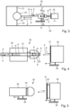
- the interferometric measuring device 1 as illustrated in Fig. 1 comprises a light source 5 that is configured to emit a measuring beam 7.
- the measuring beam 7 comprises a comparatively short temporal coherence length L.
- the measuring device 1 further comprises an optical probe 40 featuring an internal reflector 42 and being coupled to the light source 5 by a first fiber-based optical signal path 2.
- the measuring device 1 further comprises a signal analyzer 60 coupled to the optical probe 40 by a second fiber-based optical signal path 4.
- the measuring device 1 further comprises an optical compensator 20 which is arranged in the second fiber-based optical signal path 4. With the example of Fig. 2 the optical compensator 20 is arranged in the first fiber-based optical signal path 2.
- the interferometric measuring device 1 is configured to measure a distance between the optical probe 40 and a surface 51 of an object 50 by interferometry.
- the optical probe 40 is configured to generate a reference beam.
- Light transmitted to the optical probe 40 via the first fiber-based optical signal path 2 is split into a first partial beam 8 and a second partial beam 9 as illustrated in Fig. 1 .
- the second partial beam 9 is directed towards the surface 51 of the object 50, whereas the first partial beam 8 is internally reflected by the internal reflector 42 of the optical probe 40.
- the first partial beam 8 serves as a reference beam and the second partial beam 9 is a signal beam which is reflected on the surface 51 of the object 50.
- the internal reflector 42 of the optical probe 40 may be implemented as an end face of a second optical fiber 16 connecting the optical probe 40 to the light source 5 and connecting the optical probe 40 to the signal analyzer 60.
- the second partial beam 9 is at least partially reflected on the surface 51 of the object 50 and re-enters the optical probe 40. Due to the optical path difference between the internal reflector 42 and the reflective surface 51 of the object 50 there is imposed an optical path difference D between the first and second partial beams 8, 9. Typically, this path difference D is larger than the coherence length L of the light source 5.
- the optical compensator 20 arranged in the second fiber-based optical signal path 4 this macroscopic optical path difference can be at least partially compensated so that the optical path difference is entirely compensated or partially compensated at least to a degree that is smaller than the coherence length L. In this way the optical compensator 20 compensates the optical path difference and provides correspondingly compensated first and second partial beams 8', 9" or portions thereof to the signal analyzer 60.
- the optical compensator 20 that splits the measuring beam 7 as provided by the light source 5 into a first and second partial beam 8, 9.
- first and second partial beams 8, 9 propagate along the first fiber-based optical signal path 2 towards and into the optical probe 40.
- first and second partial beams 8, 9 are further split into first and second sub-beams.
- the first sub-beam 8', 9' of the first and second partial beams 8, 9 is transmitted through the internal reflector and the second sub-beam 8", 9" of first and second partial beams 8, 9 is reflected by the internal reflector 42.
- the optical path difference D between the internal reflector 42 and the surface 51 of the object matches the optical path difference of the first and second partial beams 8, 9 as provided by the optical compensator 20.
- the optical compensator 20 serves to impose a delay on the first partial beam 8 compared to the second partial beam 9.
- the optical path of the first partial beam 8 is longer by the optical path difference D compared to the optical path of the second partial beam 9.
- the second partial beam 9 precedes the first partial beam 8.
- the further optical path difference imposed by the optical probe 40 onto first and second partial beams 8, 9 is substantially of the same magnitude but compensates the optical path difference D at least between a selected pair of first and second sub-beams 9', 8" of first and second partial beams 8, 9.
- the optical compensator 20 When for instance the optical compensator 20 induces a delay onto the first partial beam 8 compared to the second partial beam 9 such that the optical path of the first partial beam 8 is larger than the optical path of the second partial beam 9, the second sub-beam 8" of the first partial beam 8 as reflected by the internal reflector 42 of the optical probe 40 will be able to interfere with a first sub-beam 9' of the second partial beam 9 which is transmitted through the internal reflector 42 and which is reflected by the surface 51 of the object 50.
- the optical path of the second sub-beam 8" of the first partial beam 8 and the optical path of the first sub-beam 9' of the second partial beam 9 is somewhat identical when the second sub-beam 8" and the first sub-beam 9' co-propagate along the second fiber-based optical signal path 4 towards the signal analyzer 60.
- an optical path difference D larger than the coherence length L and induced by one of the optical probe 40 and the optical compensator 20 is effectively compensated by the other one of the optical probe 40 and the optical compensator 20.
- at least a portion 8', 8", 9', 9" of first and second partial beams 8, 9 co-propagating towards the signal analyzer 60 will be able to interfere and to reveal relative phase shifts between the interfering partial beams 8", 9' emanating from variations of the surface or topology of the surface 51 as the optical probe 40 scans the surface 51 of the object 50 point-by-point or step-by-step.
- the light source 5 typically comprises a superluminescent diode providing a broadband spectral range of the measuring beam 7.
- the measuring beam 7 typically comprises a comparatively short temporal coherence length L.
- the coherence length L is typically shorter than the optical path difference imposed by one of the optical probe 40 and the optical compensator 20 between first and second partial beams 8, 9.
- the signal analyzer 60 comprises a demultiplexer 62 allowing to separate and/or to split the light entering via an input port 61 of the signal analyzer 60 into numerous spectral parts. Each of the selected or demultiplexed spectral parts is obtained through a respective spectral filter 63, 67, 69.
- the spectral filters 63, 67, 69 are separately and individually coupled to detectors 64, 65, 66. Each detector 64, 65, 66 may be provided with or connected to a separate spectral filter 63, 67, 69.
- the spectral filters 63, 67, 69 are optimized and designed for different wavelengths or different spectral ranges. They may have a spectral filter width (FWHM) of less than 20 nm, less than 15 nm or less than 10 nm. Some spectral filters may comprise a spectral width between 10 nm and 15 nm. They may exhibit a spectral width of about 13 nm. With other examples and for increasing the effective coherence length the spectral filters may comprise a spectral width of less than 5 mm, less than 2 nm or even less than 1 nm.
- the numerous light detectors 64, 65, 66 are coupled with a signal processor 68 that provides a processing of the signals obtained from the numerous detectors 64, 65, 66.
- a first optical circulator 10 by way of which first and second fiber-based optical signal paths 2, 4 can be divided.
- first optical circulator 10 light emanating from the light source 5 can be directed to the optical probe 40.
- Light returning from the optical probe 40 can be directed to the signal analyzer 60.
- the first optical fiber 15 is connected to a first port 11, e.g. implemented as an input port of the first optical circulator 10.
- a second port 12 of the first optical circulator 10 is connected to a second optical fiber 16.
- An opposite end of the second optical fiber 16 is connected to the optical probe 40.
- a third port 13 of the first optical circulator 10 is directed towards the signal analyzer 60.
- the third port 13 of the first optical circulator 10 is connected to an input port 21 of the optical compensator 20.
- An output port 23 of the optical compensator 20 is hence connected via a third optical fiber 18 with the input port 61 of the signal analyzer 60.
- the transmission of light from the third port 13 of the first optical circulator 10 to the input port 21 of the optical compensator 20 is provided by a fourth optical fiber 17.
- the entirely fiber-implemented signal transmission from the light source 5 to the optical probe 40 and from the optical probe 40 to the signal analyzer 60 is of particular benefit to provide a rather robust, highly reliable, precise and easily reconfigurable interferometric measuring device 1.
- the fiber-based implementation of the interferometric measuring device 1 as illustrated in Fig. 1 can be easily reconfigured into a different configuration as shown in Fig. 2 .
- the optical compensator 20 is arranged or integrated in the first fiber-based optical signal path 2.
- the input port 21 of the optical compensator 20 is connected to the first optical fiber 15.
- the fourth optical fiber 17 interconnects the output port 23 of the optical compensator 20 with the first port 11 of the first optical circulator 10.
- the second port 12 of the first optical circulator 10 is connected to the optical probe 40 via the second optical fiber 16.
- the third port 13 of the first optical circulator 10 is directly connected to the input port 61 of the signal analyzer 60 via the third optical fiber 18.
- the optical compensator 20 may comprise a housing 29.
- the optical compensator 20 further comprises an input port 21 and an output port 23.
- the optical compensator 20 further comprises a compensator head 26 and a first reflector 31.
- the first reflector 31 may be arranged on a reference body 30.
- the reference body 30 may be fixed inside the housing 29 of the optical compensator 20.
- the compensator head 26 may be moveable along the optical path extending between the compensator head 26 and the first reflector 31.
- the compensator head 26 is moveable relative to the first reflector 31 along an elongated track 28.
- the elongated track 28 may be provided by a translation stage.
- the translation stage may be servo-driven. In this way, various distances between the compensator head 26 and the first reflector 31 can be realized.
- the compensator head 26 is fiber-implemented. It is connected to the input port 21 and to the output port 23 through an internal optical fiber 19. In this way, the compensator head 26 is optically coupled to one of the first fiber-based optical path 2 and the second fiber-based optical path 4 through the internal optical fiber 19. Coupling of the internal optical fiber 19 with at least one or both, the input port 21 and the output port 23 can be provided by a second optical circulator 24.
- the input port 21 of the optical compensator may coincide with a first port of the second optical circulator 24.
- the output port 23 of the optical compensator 20 may coincide with a third port of the second optical circulator 24.
- the internal optical fiber 19 may be connected to a second port 22 of the second optical circulator 24.
- an optical beam entering the first port 21 is directed to the second port 22 and into the internal optical fiber 19.
- Light reflected by the first reflector 31 and/or a light propagating from the compensator head 26 towards the second optical circulator 24 through the internal fiber 19 is directed to the output port 23.
- the compensator head 26 comprises a second reflector 27.
- the second reflector 27 may be provided by an end face of the internal optical fiber 19 terminating in the compensator head 26.
- the second reflector 27 serves as a beam splitter.
- the measuring beam 7 enters the optical compensator 20 via the first port 21 the measuring beam 7 is split into a first partial beam 8 and a second partial beam 9.
- the first partial beam 8 is transmitted through the second reflector 27 and is reflected by the first reflector 31.
- the first partial beam 8 is reflected by the first reflector 31 and re-enters the internal optical fiber 19.
- the second partial beam 9 may be directly branched off from the measuring beam 7 as the component or portion of the measuring beam 7 that is reflected by the second reflector 27.
- the second partial beam 9 may be directly reflected by the second reflector 27 and may propagate towards the second optical circulator 24.
- first and second partial beams 8, 9 are illustrated that corresponds to the example of Fig. 1 .
- the first partial beam 8 has been reflected by the internal reflector 42 of the optical probe 40 whereas the second partial beam 9 has been reflected by the surface 51 of the object 50.
- the optical path of the first partial beam 8 is shorter compared to the optical path of the second partial beam.
- the first partial beam 8 precedes the second partial beam 9 as first and second partial beams 8, 9 enter the optical compensator 20.
- the second partial beam 9 is delayed compared to the first partial beam 8.
- the first and the second partial beams 8, 9 are each split into respective first and second sub-beams 8', 8" and 9', 9".
- the first sub-beam 8', 9' is transmitted through the second reflector 27 and the second partial beam 8", 9" is reflected by the second reflector 27.
- the compensator head 26 is further provided with an optical lens 25 configured to focus the first and second partial beams 8, 9 onto the first reflector 31.
- the optical probe 40 and the second partial beam 9 emitted by the optical probe 40 are illustrated in greater detail.
- the optical probe 40 comprises a focusing optical element, such as a lens 43 by way of which the partial beam 9 is focused.
- the partial beam 9 is typically of a Gaussian profile.
- the waist of the beam 9 in the region of a focal spot is characterized by a Rayleigh range Z R .
- Two times the Rayleigh range is illustrated in Fig. 9 .
- a surface 51, 53 of an object 50 located in the Rayleigh range may provide a reflected light beam that re-enters the optical probe 40. Beams reflected by a surface located within the Rayleigh range will substantially re-enter the optical probe 40 and hence the second optical fiber 16.
- the end face of the optical fiber towards the optical element 43 form or constitute an internal reflector 42.
- the measuring beam 7 as provided through the optical fiber 16 is split into the first partial beam 8 and the second partial beam 9 by the internal reflector 42.
- the first partial beam 8 is reflected by the internal reflector 42 and propagates towards the first optical circulator 10.
- the second partial beam 9 transmitted through the internal reflector 42 and is reflected on a front surface 51 or back surface 53 of the rather flat or thin transparent object 50.
- the reflected beam(s) 9 re-enter the optical probe 40. Since the Rayleigh range of the partial beam 9 is larger than the thickness of the object or is larger than the distance between two reflective surfaces 51, 53 it is of particular benefit when the light source 5 comprises a rather short coherence length L.
- the working distance W D of the optical probe 40 can be appropriately tuned.
- the working distance of the optical probe 40 can be appropriately adjusted such that partial beams 8, 9 reflected from one of the first and second surface 51, 53 will be able to interfere with the second partial beam 9 or a portion thereof as the respective partial beams or sub-beams 8', 9" co-propagate within the fiber towards the signal analyzer 60.
- Fig. 5 the optical compensator 20 according to the claimed invention is schematically illustrated.
- the optical compensator 20 comprises at least one piezoelectric transducer 32, 34.
- the at least one piezoelectric transducer 32, 34 one of the compensator head 26 and the first reflector 31 is moveable relative to the other one of the compensator head 26 and the first reflector 31 along the propagation direction of first and second partial beams 8, 9.
- the first reflector 31 is mounted on a piezoelectric transducer 32.
- the piezoelectric transducer 32 is fixed to the reference body 30. In this way, the reflector 31 is configured to move periodically along the propagation direction of the first and second partial beams 8, 9.
- the piezoelectric transducer 32, 34 is typically periodically driven at a driving frequency between 100 Hz and 100 kHz. This driving frequency is electronically detectable and resolvable by the signal analyzer 60 and/or by its processor 68.
- a phase shift can be periodically imposed on the interference pattern of the mutually interfering components or portions of first and second partial beams 8, 9.
- a movement of an interference pattern or a movement of interference fringes in accordance to the movement of the reflector 31 as induced by the piezoelectric transducer 32 can be monitored over time thus allowing to provide a highly precise measuring of the relative phase between the interfering portions of first and second partial beams 8, 9.
- the first reflector 31 may be implemented as a reflective mirror.
- the compensator head 26 may be void of a piezoelectric transducer. As illustrated in Fig. 5 the compensator head 26 is also provided with a piezoelectric transducer 34. The piezoelectric transducer 34 is configured to move the second reflector 27 relative to the first reflector 31 along the propagation direction of first and second partial beams 8, 9. When the compensator head 26 is provided with a piezoelectric transducer the reflector 31 and/or the reference body 30 may be void of a piezoelectric transducer 32.
- At least one or both of the first reflector 31 and the compensator head 26 is moveable relative to the other one along a track 28. Movement along the track 28 may be provided by applying or varying a DC-voltage to one of the piezoelectric transducers 32, 34. In this way, the optical path difference between first and second reflectors 31, 27 can be adapted and modified in accordance to variations of a working distance of the optical probe 40.
- at least one or both of the compensator head 26 and the first reflector 31 may be mounted on an elongated track 28 extending along the propagation direction of the first and second partial beams 8, 9.
- Providing a piezoelectric transducer 32, 34 or providing of a respective phase modulator in the optical compensator 20 is beneficial for reducing the dimensions of the optical probe 40.
- Arranging of a phase modulator and/or arranging of the piezoelectric transducer 32, 34 offset and remote from the optical probe 40 allows to miniaturize the optical probe 40 and to reduce weight of the optical probe 40. This is beneficial for a dynamic scanning operation of the optical probe, e.g. when the optical probe 40 is moved along a scanning path relative to the object 50.
- the dimensions of the optical probe 40 can be reduced to a minimum thus allowing inspecting and/or to measure surfaces of a comparatively small hollow structure of an object 50.
- the optical probe 40 may be equipped with a beam splitter 44 thus splitting the beams emitted by the optical probe towards the object 50 into a first measuring beam 45 propagating along a first direction 47 and a second measuring beam 46 propagating along a second direction 48.
- First and second directions may differ or may substantially overlap.
- the working distance W D or measuring distance along the first measuring beam 45 and the measuring distance along the second measuring beam 46 may differ.
- the first measuring beam 45 and the second measuring beam 46 may traverse different optical elements, such as different lenses featuring different focal length.
- the working distance between the beam splitter 44 and the first object 50 may differ from the working distance between the beam splitter 44 and the second object 52.
- the different geometric distances may be within the Rayleigh Z R range of the focused measuring beams 45, 46.
- An optical path difference D1 between the beam splitter 44 and a surface 51 of the first object 50 may differ by an offset DO from the optical path D2 between the beam splitter 44 and a surface 53 of the second object 52.
- This offset of the optical path differences D1, D2 may be larger than the coherence length L of the light source 5. Accordingly, in one operation mode the optical compensator 20 can be adjusted and tuned or configured correspondingly so that the interference conditions are fulfilled for beams reflected by the first object whereas the working distance and hence the optical path difference with regard to the second object 52 does not fulfill the interference conditions.
- this situation may be switched so that partial beams or sub-beams reflected by the second object 52 interfere whereas the beams or sub-beams reflected by the first object 50 do not fulfill the interference conditions.
- the optical path difference C1 between first and second reflectors 31, 27 to an optical path difference D1 between the internal reflector 42 of the optical probe 40 and a surface 51 of the first object 50 the runtime difference between at least one pair of sub-beams of first and second partial beams is effectively compensated.
- the optical path compensation can be adjusted to an optical path difference C2 that matches optical path difference D2 between the internal reflector 42 of the optical probe 40 and a surface 53 of the second object 52.
- the optical compensator 20 can be sequentially and selectively switched to different optical path offsets C1 or C2 to impose or to compensate different optical path differences D1 or D2. In this way and with one and the same setup a rather precise interferometric measurement of two surfaces of one or of two different objects can be provided.
- the working distance of the optical probe 40 can be arbitrarily adjusted so as to inspect only one of a front surface 51 and a back surface 54 of a rather thin object 50 as illustrated in Fig. 10.
- FIG. 7a shows an example of an optical probe 40 configured to generate a first and a second measuring beam 55, 46
- Fig. 7b is illustrative of a further optical probe 40 by way of which at least a first, a second and a third measuring beam 45, 46, 49 can be generated.
- the optical probe 40 of Fig. 7b has in addition a further been splitter 57 by way of which a third measuring beam 49 can be branched off towards a further, i.e. a third object 55.
- the third measuring beam 49 propagates along a third direction 58.
- a third object 55 with a third surface 56 can be measured and/or inspected.
- the surfaces 51, 53, 56 may also belong to only one or two different objects 50, 52, 55.
- the first direction 47, the second direction 48 and the first direction 58 may differ from each other.
- first direction 47 and the second direction 48 extend at a rectangular angle.
- third direction 58 extends at a predefined non-zero angle with regard to one of the first direction 47 and the second direction 48.
- third direction 58 extends at an angle between 45° to 75° with regard to one of the first direction 47 and the second direction 48.
- the angular orientation of the first direction 47, the second direction 48 and the third direction 58 may depend on the specific geometry of an object that has to be measured with the interferometric measuring device 1.
- the measuring distances along the first direction 47, the second direction 48 and the third direction 58 mutually differ.
- the optical path differences of the first measuring beam 45, the second measuring beam 46 and the third measuring beam 49 mutually differ.
- the path differences between the measuring beams 45, 46, 49 are typically smaller than or equal to a maximum of an optical path difference that can be imposed or compensated by the optical compensator 20.
- Fig. 8 a further example of the measuring device 1 is illustrated.
- the light source 5 is coupled with a beam splitter 6. While the output of the beam splitter 6 is connected to a first fiber-based optical signal path 2 the other output of the beam splitter 6 is coupled to a third fiber-based optical signal path 2'. There is also provided a fourth fiber-based optical signal path 4'.
- a first circulator 10 an optical probe 40.
- a second fiber-based optical signal path 4 extending from the optical probe 40 towards a signal analyzer 60.
- first and second optical circulators 10, 24 there are further provided.
- the setup and arrangement of the optical compensator 20, the optical probe 40, the signal analyzer 60 and the first and second optical circulators 10, 24 is substantially identical or equivalent to the setup as illustrated in Figs. 1 and 6 .
- a substantially identical setup of a measuring device is provided.
- a second optical probe 140 equipped with an internal reflector 42 is coupled to the light source 5 via a further optical circulator 110.
- the second optical compensator 120 is arranged in the third fiber-based optical signal path 2'.
- the fourth fiber-based optical signal path 4' extends from the second optical probe 140 towards the second signal analyzer 160.
- the first optical probe 40 and the first optical compensator 20 are arranged in a configuration corresponding to Fig. 1 .
- the second optical probe 140 and the second optical compensator 120 are arranged in a configuration according to Fig. 2 .
- Such a configuration is particularly useful for combining the first and the second optical compensators 20, 120 in a common optical compensator 220.
- the common optical compensator 220 may comprise a housing 229 in which the optical circulators 24, 124 and respective compensator heads 26, 126 are arranged.
- the combined optical compensator 220 comprises only one first reflector 131 serving as a common reflector for both, the compensator head 26 and the compensator head 126.
- the optical path difference C1 between the second reflector 27 and the reflector 131 is individually adjustable or modifiable compared to the optical path difference C2 between the reflector 127 of the compensator head 126 and the reflector 131.
- the compensator head 26 is adapted to compensate a first optical path difference D1 between the first optical probe 40 and the first object 50 whereas the second compensator head 126 is configured to compensate a second optical path difference D2 between the second optical probe 140 and a second object 52.
- the first and second optical probes 40, 140 as well as first and second optical compensators 20, 120 are individually coupled to first and second signal analyzers 60, 160 thus allowing and supporting simultaneous measurement of distances to two different objects 50, 52 or to simultaneously measure different surfaces 51, 53, e.g. front and back surface 51, 54 of one and the same object 50, 52.
- the second optical probe 140 and the second optical compensator 120 are arranged in a configuration according to Fig. 2 .
- the mutual arrangement of the first optical probe 40 and the first optical compensator 20 is identical or equivalent to the arrangement of the second optical probe 140 and the second optical compensator 120.
- a first measuring branch 101 and a second measuring branch 102 connected to the beam splitter 6 and each providing an interferometric measuring device as described above may be implemented substantially identically.
- Sharing one and the same first reflector 131 by at least a first compensator head 26 and a second compensator head 126 is beneficial to reduce the total number of components of the interferometric measuring device 1.
- the piezoelectric transducer 32 may be exclusively provided for the common or shared reflector 131. In this way and for first and second optical compensators 20, 120 there is only required one piezoelectric transducer 32. In this way the number of components and costs for implementing the interferometric measuring device can be decreased.
Landscapes
- Physics & Mathematics (AREA)
- General Physics & Mathematics (AREA)
- Instruments For Measurement Of Length By Optical Means (AREA)
- Length Measuring Devices By Optical Means (AREA)
- Investigating Or Analysing Materials By Optical Means (AREA)
Description
- The present disclosure relates to the field of interferometric measuring devices, in particular to fiber-implemented interferometric measuring devices for measuring a surface, a distance or profile of an object by reflection of electromagnetic radiation from the surface.
- For measuring of a surface or surface profile of an object by way of reflection of electromagnetic radiation it is known to make use of an interferometric measuring device. Document
DE10 2008 033 942 B3 discloses a fiber optically implemented optical multi-wavelength sensor for quantitatively measuring of a distance and/or of a topology of a surface by making use of two or more lasers having a wavelength between 1520 nm and 1630 nm and comprising a sensor head that is periodically spatially modulated in the direction of a measurement beam. Laser light used for such a sensor is highly coherent, both in the spatial and temporal domain. This allows to implement a highly precise measuring at a comparatively large working distance between the surface of an object and the sensor. Such devices also measure in reflection mode. Hence, at least a portion of the laser light emitted by the sensor and directed towards and onto the surface is reflected by the surface and is captured again by the sensor. Typically, the light emitted by the sensor is focused on the surface and the surface of the object is scanned in one or two dimensions by a respective relative movement between the sensor and the surface. - With a light beam focused onto a surface and reflected from the surface the surface should be located within the Rayleigh range or Rayleigh length of the focused beam. When the thickness of a transparent object is in the region or smaller than twice the Rayleigh range or Rayleigh length it is quite difficult to distinguish reflections emanating from a front surface and reflections emanating from a rear surface of the object. For measuring of a surface, a surface profile or a topology of optical components, such as lenses, it is rather important to distinguish light reflected from a front surface of the object from light that is reflected from a back surface of the object.
- Further fiber-implemented interferometric devices are known from documents
WO 2018/172119 A1 ,DE 10 2010 022421 A1 ,US 2006/103850 A1 and Chia-Chen Chang et al.: "Multiplexed Optical Fiber Sensors Using a Single Fabry-Perot Resonator for Phase Modulation", J. of Llightwave Technology, IEEE vol. 14, no. 7 (1996-07-01). - It is therefore an object of the present disclosure to provide an improved interferometric measuring device for measuring a surface, a profile or topology of an object, in particular of a transparent object, such as an optical component, e.g. of a lens, wherein the interferometric measuring device is particularly suitable for measuring of objects having comparatively small dimensions along a measuring axis or measuring direction. It is a particular aim to provide an improved interferometric measuring device that provides a well-defined and tunable or adjustable measuring depth or measuring length along a measuring direction. The working distance of the interferometric measuring device should be easily adaptable and tunable to varying measuring demands and measuring configurations. The interferometric measuring device should be rather robust in construction and operation. It should be easily reconfigurable and adaptable to different measuring scenarios and measuring conditions.
- In one aspect there is provided an interferometric measuring device for measuring a surface, a profile or topology of an object, in particular of a transparent object, such as an optical component, e.g. of a lens. The measuring device comprises a light source. The light source is configured to emit a measuring beam. The measuring beam comprises a coherence length L. Typically, the light source is of low temporal coherence and of comparatively high spatial coherence. The light source typically comprises a broadband light source, such as a superluminescent diode. The light source may also comprise an amplified spontaneous emitter (ASE) configured to generate a measuring beam produced by spontaneous emission that is optically amplified by the process of stimulated emission in a gain medium. For instance, the light source may comprise one or several superluminescent diodes or doped fiber amplifiers.
- The measuring device further comprises an optical probe comprising an internal reflector. The optical probe is coupled to the light source by a first fiber-based optical signal path. The measuring device further comprises a signal analyzer coupled to the optical probe by a second fiber-based optical signal path. The first and the second fiber-based optical signal paths may at least partially overlap. They may be implemented by one and the same optical or light transmitting component.
- The measuring device further comprises an optical compensator arranged in one of the first fiber-based optical signal path and the second fiber-based optical signal path. Particularly, the optical compensator is either arranged in the first fiber-based optical signal path or in the second fiber-based optical signal path.
- One of the optical probe and the optical compensator is configured to split the measuring beam into a first partial beam and a second partial beam and to impose an optical path difference D onto a portion of one of the first partial beam and the second partial beam relative to a portion of the other one of the first partial beam and the second partial beam. The optical path difference D imposed by the optical probe or the optical compensator is larger than the coherence length L. Typically, the optical path difference D is larger than the temporal coherence length L. The other one of the optical probe and the optical compensator is configured to compensate the optical path difference.
- By splitting the measuring beam into a first and second partial beam and by imposing an optical path difference D onto respective portions of first and second partial beams the first and second partial beam can no longer interfere and as first and second partial beams are recombined no interference pattern will be apparent on the signal analyzer. It is only and due to the other one of the optical probe and the optical compensator and due to the compensation of the optical path difference that light reflected from the internal reflector of the optical probe and light reflected from the surface of the object interferes and forms an interference fringe pattern on a detector of the signal analyzer.
- With some examples the internal reflector of the optical probe forms or constitutes a reference of the interferometric measuring device. Light reflected by the internal reflector of the optical probe and light reflected by the surface of the object and returning into the optical probe are subject to a runtime difference and hence to an optical path difference. When and as long the optical path difference between light reflected by the internal reflector and light reflected by the surface of the object is larger than the coherence length, these reflected light beams cannot interfere. For obtaining an interference pattern and for obtaining a relative phase information between the reflected partial beams, which phase information being indicative of the surface or surface profile of the object, it is provided that the optical path difference is compensated by the optical probe. With other examples, where the optical probe imposes the optical path difference between first and second partial beams it is the optical probe that serves as the optical compensator.
- Hence, with some examples it is the internal reflector of the optical probe that splits the measuring beam into the first partial beam and the second partial beam. The first partial beam is reflected by the internal reflector and returns into the second fiber-based optical signal path. The second partial beam is emitted by the optical probe towards the surface of the object. There, the second partial beam is at least partially reflected and is captured by the optical probe and coupled into the second fiber-based optical signal path. Consequently, the first partial beam and a reflected portion of the second partial beam co-propagate into the second fiber-based optical signal path towards the signal analyzer.
- As long as the optical path difference between the first partial beam and the reflected portion of the second partial beam is larger than the coherence length, these two beams cannot interfere. It is then due to the optical compensator at least partially or completely compensating the optical path difference in a well-defined and deterministic, e.g. constant way for a particular measurement, thus allowing and enabling the first partial beam and the reflected portion of the second partial beam to interfere.
- With this example the optical compensator is arranged or integrated in the second fiber-based optical signal path. Here, the optical probe may be directly coupled to the light source. Light returning from the optical probe is coupled into the optical compensator. Thereafter it is coupled to the signal analyzer.
- With other examples it is the optical compensator that splits the measuring beam provided by the light source into a first partial beam and a second partial beam. There is imposed an optical path difference D onto at least a portion of one of the first and second partial beams relative to a respective portion of the other one of the first and second partial beams. Here, it is the optical probe, in particular the optical path difference between the internal reflector of the optical probe and the surface of the object that leads to a compensation of the optical path difference previously imposed by the optical probe. With this example the optical compensator is arranged or integrated in the first fiber-based optical signal path and the second fiber-based optical signal path extends from the optical probe to the signal analyzer.
- Typically and with further examples, the optical probe and the optical compensator mutually complement and correspond to each other. A degree of compensation of the optical path difference provided by the optical compensator typically matches the optical path difference between the internal reflector of the optical probe and the surface of the object. Typically, the surface of the object is quantitatively known and the degree of compensation provided by the optical compensator matches the optical path difference between the internal reflector and the surface of the object. Variations of an interference pattern detectable by the signal analyzer as the optical probe scans along the surface provides measurement data being indicative of the surface properties, in particular of the surface profile or topology of the surface on a microscopic scale.
- The same is valid when the optical compensator is configured to split the measuring beam into a first partial beam and a second partial beam and wherein the optical probe compensates the optical path difference of at least of portions of first and second partial beams.
- The two possible and alternative arrangements of the optical compensator in one of the first fiber-based optical signal path and the second fiber-based optical signal path allows for a rather flexible configuration of the interferometric measuring device. The interferometric measuring device may be easily reconfigured and adapted to different measurement demands and measuring conditions. Moreover, providing of first and second fiber-based optical signal paths is of great practical use. The light source, the optical probe, the signal analyzer and the optical compensator may be all provided with fiber optical ports or connectors thus enabling a rather robust and highly reliable interferometric measuring device, which is easily reconfigurable to varying measuring demands and measuring conditions.
- With examples, wherein the optical compensator is located or integrated in the first fiber-based optical signal path, the total intensity provided at the optical probe is smaller compared to examples, wherein the optical compensator is located or integrated in the second fiber-based optical signal path. With some examples and with the optical compensator in the first fiber-based optical signal path, only a portion of the initial light intensity as provided by the light source will be transferred to the optical probe. In this way, the optical probe may easily fulfill regulatory demands in terms of a laser protection class or light protection class.
- With other examples, and when the optical compensator is located in the second fiber-based optical signal path, the light intensity available at the optical probe can be increased. This may be of particular benefit in such cases, wherein an optical reflectivity of the object is rather low and/or when the total power of the light sources is comparatively small.
- According to a further example the light source comprises an amplified stimulated emitter and/or a superluminescent diode. Typically, the light source features a rather large spatial coherence and a rather short temporal coherence. The coherence length, in particular the temporal coherence length is comparatively short. It is typically smaller than 5 cm, smaller than 1 cm or even smaller than 1 mm.
- Moreover, the coherence length L, in particular the temporal coherence length of the light source is smaller than a Rayleigh range of a focusing lens of the optical probe by way of which the measuring beam and/or one of the first or second partial beams is emitted onto the surface of the object. In this way, the interferometric measuring device can be easily tuned and adapted to precisely measure only one of a plurality of surfaces that lie within or cross the Rayleigh range of the optical probe.
- According to a further example the first fiber-based optical signal path comprises a first optical fiber and a second optical fiber. The first optical fiber connects the light source to a first optical circulator. The second optical fiber connects the first optical circulator to the optical probe. In this way the entire optical path starting from the light source and terminating at the optical probe is fiber-based or fiber-implemented. There is no free beam propagation between the light source and the optical probe. This provides a rather robust and highly reliable implementation of the measuring device. In addition, the first optical fiber may be detachably connected to the first optical circulator. Likewise, the second optical fiber may be detachably connected to at least one of the first optical circulator and the optical probe. In this way the measuring device can be easily reconfigured to adapt and to conform with varying measuring demands or configurations.
- With a further example the second fiber-based optical signal path comprises the second optical fiber and a third optical fiber. The third optical fiber connects the signal analyzer to the optical circulator. Insofar, the third optical fiber and the second optical fiber provide transmission of light from the optical probe via the first optical circulator towards the signal analyzer. The second fiber-based optical signal path is hence configured to direct or to transmit radiation reflected by the surface of the object towards the signal analyzer.
- Here, the second optical fiber may be implemented as a bi-directional optical fiber. The second optical fiber provides transmission of light from the first optical circulator to the optical probe. At the same time the second optical fiber provides transmission of light reflected by the object and captured by the optical probe towards the signal analyzer.
- Typically, the first optical circulator is a three-port circulator. A first port of the first optical circulator is connected to the first optical fiber, a second port of the first optical circulator is connected to the second optical fiber and a third port of the first optical circulator is connected to the third optical fiber. Light entering the first port is transmitted to the second port and is hence transmitted via the second optical fiber towards the optical probe. Light reflected by the object and/or reflected by the internal reflector of the probe returns to the first optical circulator. There, it does not return into the first optical fiber but it is directed via the third port of the first optical circulator towards and into the third optical fiber.
- The implementation of a first optical circulator provides optical beam and hence signal transmission from the light source towards the optical probe and in a return direction, hence from the optical probe towards the signal analyzer. Here, it is of particular benefit, that the optical probe and the first optical circulator can be connected by only one, namely by the second optical fiber. This helps to reduce the number of components to implement the interferometric measuring device.
- Generally, also a fiber coupler could be implemented instead of an optical circulator.
- With some examples of the interferometric measuring device, in particular when the optical compensator is arranged or integrated in the first fiber-based optical signal path the first optical fiber terminates in an input port of the optical compensator. An output port of the optical compensator is connected in a fiber-based way to the first port of the optical circulator. The fiber-based connection between the optical compensator and the first optical circulator may be implemented and provided by a fourth optical fiber. The optical compensator may be detachably connectable to the first optical fiber and/or to the fourth optical fiber. In this way the optical compensator is removably arranged or integrated in the first fiber-based optical signal path.
- With other examples and when the optical compensator is arranged or integrated in the second fiber-based optical signal path the third port of the first optical circulator is connected to an input port of the optical compensator by the fourth optical fiber. An output port of the optical compensator is connected to the signal analyzer by the third optical fiber. Also here, fourth and third optical fibers may be detachably connected to the optical compensator.
- The input port and the output port of the optical compensator may comprise a fiber coupling. The first port, the second port and the third port of the first optical circulator may comprise corresponding fiber couplers. Also the optical probe and the light source may be provided with respective optical couplers allowing for a detachable connection of optical fibers.
- With typical examples the signal analyzer comprises a demultiplexer and at least one detector, e.g. a photodiode or a spatial light detector. Moreover, the signal analyzer comprises at least a processor connected to the at least one light detector. The processor provides digital signal processing of signals generated by the at least one light detector. Typically, the signal analyzer comprises numerous light detectors, each of which separately connected to the demultiplexer. The at least one or several light detectors may be each provided with or coupled to a separate optical, i.e. spectral filter. Typically, the at least one or more optical or spectral filters are provided by the demultiplexer. The demultiplexer may comprises the at least one or several spectral filters, wherein an output of each filter is connected to one of the light detectors.
- This arrangement provides a wavelength selective detection of signals by one or several detectors. A first detector may be coupled to a first spectral filter of the demultiplexer to detect interference signals on the basis of a first spectral range or at a first wavelength. A second detector may be coupled to a second optical and/or spectral filter of the demultiplexer to detect an interference pattern on the basis of a second spectral range or at a second wavelength different to the first spectral range or different to the first wavelength. A multi-wavelength or multi-spectral range analysis increases the spatial measurement range of the interferometric measuring device. The interferometric measuring device, in particular the broadband light source generally provides an interference for a large variety of different wavelength or spectral ranges. With the demultiplexer or spectral filter of the signal analyzer multiple interference patterns at discrete and different wavelengths can be analyzed simultaneously.
- The demultiplexer may be configured to operate on one of a coarse wavelength division multiplexing (CWDM) scheme and a dense wavelength division multiplexing (DWDM) scheme.
- Moreover, by appropriately selecting the spectral width of the at least one filter of the demultiplexer the effective coherence length can be appropriately varied. By decreasing the spectral width of the at least one spectral filter of the demultiplexer, the coherence length can be effectively increased. By increasing the spectral width of the at least one spectral filter of the demultiplexer the coherence length can be effectively reduced. Typically, with spectral filters featuring a spectral width (FWHM) of less than 1 nm a coherence length of more than 2 mm, typically between 2 mm and 3 mm can be obtained. Moreover, with spectral filters featuring a spectral with of more than 15 nm, e.g. of about 10 nm - 20 nm a coherence length of less than 200 µm, less than 150 µm or even less than 120 µm can be obtained.
- With typical examples, the light source comprises a broadband light source featuring a spectral width of more than 50 nm (full with half maximum (FWHM)), more than 70 nm, more than 90 nm or even more than 100 nm. The spectrum of the light source may exhibit at least two or even more rather broad peaks. With some examples the spectrum of the light source comprises three peaks, each of which having a spectral with (FHWM) of more than 10 nm, more than 15 nm, more than 20 nm and/or or less than 30 nm, less than 25 mm or less than 20 nm.
- The spectral filters combined with the numerous optical detectors may comprise a spectral with (FHWM) of less than 20 nm, less than 15 nm or less than 10 nm. Some spectral filters comprise a spectral width between 10 nm and 15 nm. They may exhibit a spectral width of about 13 nm. Depending on the wavelength of the broadband light source and/or or depending on the spectral width of the at least one filter between the demultiplexer and the at least one detector, a coherence length L of less than 200 µm, less than 180 µm, less than 150 µm, less than 120 µm or less than 100 µm can be obtained. With some examples, the coherence length is between 160 µm and 200 µm, between 175 µm and 200 µm, or between 180 µm and 200 µm.
- According to the invention, the optical compensator comprises a compensator head and first reflector. The compensator head is configured to direct one of the measuring beam, the first partial beam, the second partial beam or a portion thereof towards the first reflector. Typically, the compensator head is also configured to capture light reflected by the first reflector in response to the transmission or direction of one of the first partial beam, the second partial beam or a portion thereof towards the first reflector. Typically, there is implemented a free beam propagation between the compensator head and the first reflector. The compensator head and the first reflector may be encapsulated in a housing. This allows to reduce external disturbances or perturbations to a minimum.
- By means of the compensator head and the first reflector an optical path difference can be either imposed on first and second partial beams generated by the compensator head and the first reflector. Typically, the optical path difference between the compensator head and the first reflector coincides, matches with or is adjustable to an optical path difference between the surface of the object and the internal reflector of the optical probe. The optical path difference between the compensator head and the first reflector does not have to be identical to the optical path difference of the internal reflector and the surface of the object. The respective deviation between the optical path difference provided by the optical compensator and the optical path difference provided by the optical probe must be smaller than the coherence length of the light source. In this way an optical path difference between first and second partial beams or portions thereof can be effectively compensated and respective light beams provided to the signal analyzer may interfere.
- According to a further example the compensator head is optically coupled to one of the first fiber-based optical path and the second fiber-based optical path through an internal optical fiber. In this way the compensator head is arranged in or integrated into one of the first fiber-based optical signal path and the second fiber-based optical signal path. In this way, a rather robust and reliable optical coupling of the compensator head with one of the light source, the optical probe and the signal analyzer can be provided.
- Via the internal optical fiber the compensator head is optically coupled to at least one or both of an input port and an output port of the optical compensator. The fiber-based connection of the compensator head to at least one or to both, the input port and the output port of the optical compensator allows for a moveable arrangement of the compensator head inside a housing of the optical compensator.
- With some further examples the compensator head may be detachably connectable to at least one of the input port and the output port via the internal optical fiber. Here, the internal optical fiber may be detachably connectable to the compensator head. In this way numerous and differently configured compensator heads can be used with the optical compensator, e.g. to modify the imposing of an optical path difference or to modify a compensation of the optical path difference between the first partial beam, the second partial beam and/or portions thereof.
- According to the invention, the compensator head comprises a second reflector.
- The second reflector is configured to split the measuring beam into the first partial beam and the second partial beam. Here, both, the first partial beam and the second partial beam are transmitted towards the optical probe. With this example the optical compensator is arranged or integrated in the first fiber-based optical signal path. The second reflector is a partial reflector. It may be implemented as a beam splitter. The first partial beam may be reflected at the second reflector and may thus return into the internal optical fiber. The second partial beam is transmitted by the second reflector and is directed towards the first reflector. There, the second partial beam is reflected and returns to the compensator head. The reflected second partial beam re-enters the compensator head and the internal optical fiber. In this way and by the optical path difference between the first and second reflectors of the compensator an optical path difference can be imposed between the first and second partial beam or portions thereof. Typically, the optical path difference imposed by the optical compensator matches in size with the optical path difference imposed on the respective beam or beam portions by the optical probe.
- With another example the compensator head comprises the second reflector. Here the second reflector is configured to split the first partial beam into first and second sub-beams of the first partial beam and to split the second partial beam into first and second sub-beams of the second partial beam. This configuration of the compensator head particularly applies when the optical compensator is arranged or integrated in the second fiber-based optical signal path. Here, the first partial beam and the second partial beam are already provided with the optical path difference D. Typically, the first sub-beams of the first and second partial beams are transmitted by the second reflector. They are reflected by the first reflector. The reflected first sub-beams may then re-enter the second fiber-based optical path. The second sub-beams of the first and second partial beams are reflected by the second reflector. The reflected second sub-beams may remain in the second fiber-based optical path.
- First and second partial beams have been generated and/or the optical path difference has been imposed by the optical probe. First and second partial beams are typically split from the measuring beam by the internal reflector of the optical probe. Splitting of the measuring beam into first and second partial beams provided by the internal reflector of the optical probe may be somewhat equivalent or substantially identical to the above described splitting of the measuring beam into first and second partial beams as provided by the second reflector of the compensator head. It may be provided by a fiber end face.
- With the optical probe, in particular by the internal reflector of the optical probe, the measuring beam may be split into a first partial beam and a second partial beam. The first partial beam returns into the optical probe and/or into the optical fiber typically connecting the optical probe with the first optical circulator. The second partial beam is transmitted by the internal reflector and is directed, e.g. focused on the surface of the object. There, the second partial beam or at least a portion thereof is reflected and returns into the optical probe and into the respective fiber. In this way, an optical path difference is imposed between the first and second partial beams or portions thereof.
- With the present example and when the optical probe provides a splitting of the measuring beam into first and second partial beams and wherein the optical compensator is arranged in the second fiber-based optical signal path the first partial beam is split into first and second sub-beams and the second partial beam is likewise split into first and second sub-beams by the optical compensator. Here, a first sub-beam of the first partial beam is transmitted through the second reflector and is directed towards the first reflector. There, the first sub-beam of the first partial beam is reflected and returns into the compensator head. The second sub-beam of the first partial beam is reflected by the second reflector and returns directly into the compensator head and/or into the internal optical fiber. Both, the first and second sub-beams of the first partial beam co-propagate in the internal optical fiber towards an output port of the optical compensator. Due to the optical path difference between the first and the second reflectors first and second sub-beams of the first partial beam comprise a respective optical path difference.
- The same is valid for the second partial beam. Here, a first sub-beam of the second partial beam is transmitted through the second reflector and is hence directed towards the first reflector. There, the first sub-beam of the second partial beam or at least a portion thereof is reflected towards the compensator head. The reflected sub-beam or at least a portion thereof is captured by the compensator head and is coupled into the internal optical fiber. The second sub-beam of the second partial beam is directly reflected by the second reflector and is coupled into the internal optical fiber. In this way also first and second sub-beams of the second partial beam co-propagate in the internal optical fiber towards an output port of the optical compensator. Since there is imposed an optical path difference between the reflected co-propagating first and second sub-beam of the second partial beam these sub-beams cannot interfere.
- Rather, an optical path difference C is imposed on the first sub-beam of the second partial beam compared to the second sub-beam of the first partial beam in such a way that the first sub-beam of the second partial beam is delayed compared to second sub-beam of the first partial beam. This optical path difference is equal to or at least similar in magnitude to the optical path difference imposed between first and second partial beam by the optical probe. The delay imposed by the probe onto the second partial beam relative to the first partial beam is effectively compensated by a delay imposed by the optical compensator onto the first sub-beam of the first partial beam relative to the second sub-beam of the first partial beam.
- In further examples, wherein the optical compensator is arranged in the first fiber-based optical signal path and wherein the optical compensator splits the measuring beam into first and second partial beams, it is the internal reflector of the optical probe that is configured to split the first partial beam into first and second sub-beams of the first partial beam and to split the second partial beam into first and second sub-beams of the second partial beam. Here, the roles and functions of the second reflector and the internal reflector of the optical probe interchange.
- With some examples, wherein the optical compensator is arranged in the first fiber-based optical signal path and wherein the measuring beam as provided by the light source is split into first and second partial beams by the optical compensator, the first partial beam is delayed compared to the second partial beam by the optical path difference D. Now and with the optical probe the first sub-beam of the second partial beam is transmitted by the internal reflector and the second sub-beam of the first partial beam is reflected by the internal reflector.
- This imposes a compensating optical path difference between the second sub-beam of the first partial beam compared to the first sub-beam of the second partial beam. This optical path difference typically matches the optical path difference imposed by the optical probe and as governed by the optical path difference between the internal reflector and the surface of the object.
- In this way the optical path difference between first and second partial beams and as imposed by the optical probe is effectively compensated with the second sub-beam of the first partial beam and the first sub-beam of the second partial beam. These sub-beams and the optical path differences imposed on these sub-beams mutually compensate.
- Generally, it is sufficient, when the compensation of the optical path difference reduces the total optical path difference of the second sub-beam of the first partial beam and the first sub-beam of the second partial beam to an optical path difference that is smaller than the coherence length of the light source. In this way the second sub-beam of the first partial beam and the first sub-beam of the second partial beam may interfere and provide an interference pattern on the signal analyzer.
- With other examples, wherein the optical compensator is arranged in the first fiber-based optical signal path it is the second reflector that splits the measuring beam into the first partial beam and the second partial beam. Then the first partial beam is split into first and second sub-beams of the first partial beam by the internal reflector of the optical probe. The internal reflector of the optical probe further provides splitting of the second partial beam into first and second sub-beams of the second partial beam. Here, the second partial beam precedes the first partial beam as they enter the optical probe. Hence, the first partial beam is provided with a delay compared to the first partial beam due to an increased optical path difference between the first and second reflectors of the optical compensator.
- Now and when the first and second partial beams enter the optical probe it is the first sub-beam of the first partial beam that propagates through the internal reflector while the second sub-beam of the first partial beam is reflected by the internal reflector of the optical probe. The reflected second sub-beam of the first partial beam returns into the respective optical fiber. Moreover, the first sub-beam of the second partial beam propagates through the internal reflector and is directed towards the surface of the object. There, at least a portion of the first sub-beam of the second partial beam is reflected and re-enters the optical probe and the respective fiber. Also here, the first sub-beam of the second partial beam is configured to interfere with the second sub-beam of the first partial beam.
- According to the invention, an optical path difference between the first reflector and the second reflector is modifiable and/or adjustable. By adjusting or modifying the optical path difference between the first and second reflectors the working distance of the optical probe can be modified and/or adjusted accordingly. In this way rather thin optical components, such as comparatively thin lenses can be analyzed and measured with the interferometric measuring device. Typically, the coherence length, e.g. the temporal coherence length of the light source is smaller than a thickness of the reflective object. With a given distance between the optical probe and the surface of the object there is defined a respective optical path difference between the surface of the object and the internal reflector.
- With the optical compensator, a respective optical path difference can be set or adjusted between the first and second reflectors. In this way the optical path difference between the internal reflector of the optical probe and the surface of the object can be compensated on a macroscopic scale. Further optical path differences on a microscopic scale that emanate from the topology, the surface or the profile of the object and being shorter than the coherence length of the light source can be measured by the interferometric measuring device. Surface or profile deviations of the surface of the object lead to variations in the interference pattern obtainable at the signal analyzer as the optical probe scans the surface of the object, e.g. point-by-point.
- According to the invention, one of the compensator head and the first reflector is moveable relative to the other one of the compensator head and the first reflector along a track. The track may comprise an elongated track. The track may extend along the propagation direction of one of the measuring beam, the first partial beam and the second partial beam as the respective beams propagate from the compensator head towards the first reflector and/or from the first reflector back into the compensator head.
- By moving the first reflector along a track, e.g. along an elongated or straight-shaped track the optical path difference between the first reflector and the second reflector of the optical compensator is easily modifiable and/or adjustable. Typically, at least one of the first reflector and the compensator head is mounted on a translation stage or on some other moveable device allowing and supporting varying of the optical path difference between first and second reflectors of the optical compensator. There may be provided an electromechanical drive, by way of which the compensator head is moveable relative to the first reflector along the track. The track may comprise a guide rail along which at least one of the compensator head and the first reflector is moveable relative to the other one of the compensator head and the first reflector.
- According to the invention, the optical compensator comprises at least one piezoelectric transducer and wherein one of the compensator head and the first reflector is movable relative to the other one of the compensator head and the first reflector by the piezoelectric transducer. The piezoelectric transducer imposes a movement of the compensator head relative to the first reflector along the propagation direction of the first partial beam and the second partial beam.
- The piezoelectric transducer may comprise a series or a stack of numerous piezoelectric layers each of which providing a shift of the optical path between first and second reflectors of the optical compensator. The piezoelectric transducer may be sufficient to modify the optical path difference between the first and second reflectors. With some examples the piezoelectric transducer is provided in addition to a moveable arrangement of the first reflector relative to the second reflector, hence in addition to a moveable arrangement of the compensator head relative to the first reflector.
- With some examples the compensator head is arranged on a translation stage whereas the first reflector is fixed inside the housing of the optical compensator. Here, the piezoelectric transducer may be arranged between the translation stage and the compensator head or it may be arranged between the housing and the first reflector. Likewise, it is also conceivable that the compensator head is substantially fixed inside the housing of the optical compensator and that the first reflector is mounted on a translation stage for moving the first reflector relative to the second reflector.
- According to the invention, the piezoelectric transducer is periodically driven at a driving frequency between 100 Hz and 100 kHz. Periodically driving the transducer provides a phase shift on the respective partial beam or sub-beam of a partial beam. In this way, the signal processing, in particular the determination of the relative phase between the interfering sub-beams of first and second partial beams on the signal analyzer can be improved. As the piezoelectric transducer is periodically driven the phase of the interference pattern on a respective detector of the signal analyzer is subject to a corresponding movement.
- This movement is detectable and analyzable by the signal processing connected to the respective detector. The variation of the measurable intensity of an interference pattern or interference fringe on the detector dependent over the phase shift of the interfering sub-beams is quantitatively and rather precisely known. Modifying the phase between the interfering sub-beams through the periodic driving of the piezoelectric transducer thus enables to precisely determine the relative phase between the interfering sub-beams. Relative phases being as small as 1/1000 of the wavelength can be precisely determined in this way. The precision of the measuring device can be thus improved.
- According to a further example the second reflector coincides with or is formed by an end face of the internal optical fiber. In this way a rather compact and robust design of the second reflector can be provided. The compensator head may further comprise an optical element, such as a focusing lens by way of which light emitted by the fiber end face is focused on the first reflector. With the same optical component, e.g. with the same lens, light reflected by the first reflector can be coupled back into the internal optical fiber through its respective end face.
- Similarly, also the internal reflector of the optical probe may coincide with or may be formed by an end face of the second optical fiber terminating in or at the optical probe. This allows and supports a rather compact design of the optical probe. This is of particular benefit when the optical probe should be used for the measuring of comparatively small hollow objects. In this way, the optical probe can be for instance used to measure an inside surface of a hollow structure, such as an inside surface of a cylindrical object.
- According to a further example the optical compensator comprises a second optical circulator. The second optical circulator comprises a first port, a second port and a third port. The second port is optically coupled to the compensator head. Insofar, light entering the optical compensator via the first port is directed to the second port and hence to the compensator head. Insofar, light entering the first port is directed to the compensator head. Light returning from the compensator head, e.g. light reflected by the first and/or second reflectors of the optical compensator is directed to the third port. Here, the first port is an input port and the third port is an output port.
- According to a further example the first port of the second optical circulator is connected to the light source and the third port is connected to the first optical circulator. Alternatively, the first port of the second optical circulator is connected to the first optical circulator and the third port of the second optical circulator is connected to the signal analyzer.
- With examples, wherein the optical compensator is arranged or integrated in the first fiber-based optical signal path the first port of the second optical circulator is connected to the light source and the third port of the optical compensator is connected to a third port of the first optical circulator. With other examples, wherein the optical compensator is arranged or integrated in the second fiber-based optical signal path the first port of the second optical circulator is connected to a third port of the first optical circulator. The third port of the second optical circulator is connected to an input port of the signal analyzer.
- According to another example the optical probe comprises a beam splitter configured to emit a first measuring beam and a second measuring beam. Particularly, the beam splitter is configured to emit the first measuring beam in a first direction or to a first object. The beam splitter is further configured to emit the second measuring beam in a second direction and/or to a second object. By means of the beam splitter the optical probe is enabled to measure the distance to a surface of the object along two different directions or to measure a first distance to a first object and to measure a second distance to a second object.
- Typically, a first working distance along the first direction may differ from a second working distance along the second direction. The distance difference along first and second measuring directions is typically larger than the coherence length of the light source. In this way the measuring device may easily switch between a measurement along the first direction or to the first object and measuring of a distance along the second direction and/or to the second object by adjusting the optical path difference imposed or compensated by the optical compensator.
- When a distance along the first direction or to the first object should be measured, the optical compensator is configured in accordance to the optical path difference between the internal reflector of the optical probe and the surface of the first object or the surface detectable along the first measuring direction. In other configurations and when the second measuring beam should be activated the optical compensator is used to compensate the optical path difference between the internal reflector of the optical probe and the surface of the second object or the surface of an object measured along the second direction.
- By modifying the optical path difference between first and second reflectors of the optical compensator, the working distance of the optical probe along first and second directions can be adjusted and modified. Only such beams will be subject to a measurable interference on the signal analyzer that are reflected along or counter the first and second directions and which are reflected by first or second objects and having an optical path difference that matches with the optical path difference imposed or compensated by the optical compensator.
- According to another example the measuring device further comprises a second optical probe comprising an internal reflector and coupled to the light source by a third fiber-based optical signal path. The measuring device further comprises a second signal analyzer coupled to the second optical probe by a fourth fiber-based optical signal path. There is further provided a second optical compensator arranged in one of the third fiber-based optical signal paths and the fourth fiber-based optical signal path.
- In this way the first optical probe and the first optical compensator may be mutually adjusted to provide measuring of the surface or profile of the object at a first working distance from the first optical probe. Concurrently and simultaneously the second optical probe and the second optical compensator may be mutually adjusted to measure a surface or profile of the object at a second working distance that differs from the first working distance. Likewise, and depending on the orientation of first and second optical probes the surface, the profile or topology of different objects or measuring of respective first and second distances along different first and second directions can be measured simultaneously. The first and second signal analyzer may share a signal processor. With some examples first and second signal analyzer are each provided with a separate signal processor.
- As described above in connection with the optical probe and the optical compensator, also one of the second optical probe and the second optical compensator is configured to split the measuring beam into a first partial beam and a second partial beam and to impose an optical path difference onto a portion of one of the first and second partial beams relative to a portion of the other one of the first and second partial beams. Also here, the optical path difference is larger than the coherence length. The other one of the second optical probe and the second optical compensator is configured to compensate the optical path difference. In principle, the second optical probe is implemented similarly or identically to the optical probe as described above. The same is valid for the second optical compensator compared to the optical compensator as described above and to the second signal analyzer compared to the signal analyzer as described above.
- According to a further example first and second optical compensators may be coupled in that they share at least one optical component. With some examples at least one reflector is shared by the first optical compensator and the second optical compensator. The first optical compensator comprises a first compensator head directed towards a common reflector representing the first reflector. Likewise, the second optical compensator comprises a second compensator head directed to the same, hence to the common reflector or first reflector.
- Here it may be of particular benefit, when the common or shared reflector is fixed to a support or to a housing of first and second optical compensators. The first compensator head and the second compensator head may be independently moveable in the housing relative to the common or shared reflector. In this way the first and the second optical compensators are configured to provide compensation or imposing of different optical path differences between first and second partial beams or portions thereof.
- With a further example the at least one reflector shared by the first and second optical compensators is supported by the piezoelectric transducer. In this way and for the implementation of first and second optical compensators in a common housing there is required only one first reflector and only one piezoelectric transducer. In this way and by arranging first and second compensator heads in a common housing and/or by directing first and second compensator heads of first and second optical compensators to a common reflector a number of components of such a combined first and second optical compensator can be reduced compared to embodiments or examples, wherein each optical compensator comprises a compensator head and an own first reflector and/or an own piezoelectric transducer.
- The measuring device as described above is by no way limited to the implementation of first and second optical probes, signal analyzers and optical compensators. Due to the fiber optic implementation the measuring device is expandable to numerous optical probes, signal analyzers and optical compensators thus allowing to realize numerous different working distances, e.g. along different directions simultaneously.
- In the following, some examples of the interferometric measuring device are described in greater detail by making reference to the drawings, in which:
- Fig. 1
- is indicative of one example of the interferometric measuring device,
- Fig. 2
- is indicative of a further example of the interferometric measuring device,
- Fig. 3
- shows a schematic illustration of the internal structure of the optical compensator,
- Fig. 4
- is illustrative of first and second partial beams and respective sub-beams propagating between the compensator head and the first reflector of the optical compensator,
- Fig. 5
- shows the implementation of the piezoelectric transducer in the optical compensator,
- Fig. 6
- is illustrative of an example of the interferometric measuring device, wherein the optical probe is configured to measure a distance to a reflective surface along a first and a second direction,
- Fig. 7a
- shows one example of an optical probe in accordance to
Fig. 6 , - Fig. 7b
- shows a further example of an optical probe,
- Fig. 8
- is illustrative of a measuring device comprising first and second optical probes, first and second signal analyzers and first and second optical compensators, and
- Fig. 9
- schematically illustrates focusing of a measuring beam on a reflective surface of a comparatively thin transparent object.
- The
interferometric measuring device 1 as illustrated inFig. 1 comprises alight source 5 that is configured to emit ameasuring beam 7. Themeasuring beam 7 comprises a comparatively short temporal coherence length L.The measuring device 1 further comprises anoptical probe 40 featuring aninternal reflector 42 and being coupled to thelight source 5 by a first fiber-basedoptical signal path 2. The measuringdevice 1 further comprises asignal analyzer 60 coupled to theoptical probe 40 by a second fiber-basedoptical signal path 4. The measuringdevice 1 further comprises anoptical compensator 20 which is arranged in the second fiber-basedoptical signal path 4. With the example ofFig. 2 theoptical compensator 20 is arranged in the first fiber-basedoptical signal path 2. - The
interferometric measuring device 1 is configured to measure a distance between theoptical probe 40 and asurface 51 of anobject 50 by interferometry. Theoptical probe 40 is configured to generate a reference beam. Light transmitted to theoptical probe 40 via the first fiber-basedoptical signal path 2 is split into a firstpartial beam 8 and a secondpartial beam 9 as illustrated inFig. 1 . The secondpartial beam 9 is directed towards thesurface 51 of theobject 50, whereas the firstpartial beam 8 is internally reflected by theinternal reflector 42 of theoptical probe 40. Here the firstpartial beam 8 serves as a reference beam and the secondpartial beam 9 is a signal beam which is reflected on thesurface 51 of theobject 50. - The
internal reflector 42 of theoptical probe 40 may be implemented as an end face of a secondoptical fiber 16 connecting theoptical probe 40 to thelight source 5 and connecting theoptical probe 40 to thesignal analyzer 60. The secondpartial beam 9 is at least partially reflected on thesurface 51 of theobject 50 and re-enters theoptical probe 40. Due to the optical path difference between theinternal reflector 42 and thereflective surface 51 of theobject 50 there is imposed an optical path difference D between the first and secondpartial beams light source 5. - As the first
partial beam 8 and a reflected portion 9' of the secondpartial beam 9 co-propagate along the secondoptical fiber 16 from theoptical probe 40 towards thesignal analyzer 60 these beams are originally not able to interfere because the optical path difference D is larger than the coherence length L. With theoptical compensator 20 arranged in the second fiber-basedoptical signal path 4 this macroscopic optical path difference can be at least partially compensated so that the optical path difference is entirely compensated or partially compensated at least to a degree that is smaller than the coherence length L. In this way theoptical compensator 20 compensates the optical path difference and provides correspondingly compensated first and secondpartial beams 8', 9" or portions thereof to thesignal analyzer 60. - As illustrated in
Fig. 1 the optical path of the firstpartial beam 8 differs from the optical path of the secondpartial beam 9 by the optical path difference D = 2Δd, with Δd being the distance between theinternal reflector 42 and thereflective surface 51 of theobject 50. - In the other setup as illustrated in
Fig. 2 it is theoptical compensator 20 that splits themeasuring beam 7 as provided by thelight source 5 into a first and secondpartial beam - In
Fig. 2 , the first and secondpartial beams optical signal path 2 towards and into theoptical probe 40. There, both, first and secondpartial beams partial beams second sub-beam 8", 9" of first and secondpartial beams internal reflector 42. The optical path difference D between theinternal reflector 42 and thesurface 51 of the object matches the optical path difference of the first and secondpartial beams optical compensator 20. - As illustrated in
Fig. 2 , theoptical compensator 20 serves to impose a delay on the firstpartial beam 8 compared to the secondpartial beam 9. Hence, the optical path of the firstpartial beam 8 is longer by the optical path difference D compared to the optical path of the secondpartial beam 9. The secondpartial beam 9 precedes the firstpartial beam 8. The further optical path difference imposed by theoptical probe 40 onto first and secondpartial beams second sub-beams 9', 8" of first and secondpartial beams - When for instance the
optical compensator 20 induces a delay onto the firstpartial beam 8 compared to the secondpartial beam 9 such that the optical path of the firstpartial beam 8 is larger than the optical path of the secondpartial beam 9, thesecond sub-beam 8" of the firstpartial beam 8 as reflected by theinternal reflector 42 of theoptical probe 40 will be able to interfere with a first sub-beam 9' of the secondpartial beam 9 which is transmitted through theinternal reflector 42 and which is reflected by thesurface 51 of theobject 50. - On a macroscopic scale the optical path of the
second sub-beam 8" of the firstpartial beam 8 and the optical path of the first sub-beam 9' of the secondpartial beam 9 is somewhat identical when thesecond sub-beam 8" and the first sub-beam 9' co-propagate along the second fiber-basedoptical signal path 4 towards thesignal analyzer 60. - With either implementation of the
optical compensator 20 and theoptical probe 40 as illustrated inFigs. 1 and 2 , an optical path difference D larger than the coherence length L and induced by one of theoptical probe 40 and theoptical compensator 20 is effectively compensated by the other one of theoptical probe 40 and theoptical compensator 20. In this way, at least aportion 8', 8", 9', 9" of first and secondpartial beams signal analyzer 60 will be able to interfere and to reveal relative phase shifts between the interferingpartial beams 8", 9' emanating from variations of the surface or topology of thesurface 51 as theoptical probe 40 scans thesurface 51 of theobject 50 point-by-point or step-by-step. - The
light source 5 typically comprises a superluminescent diode providing a broadband spectral range of themeasuring beam 7. Themeasuring beam 7 typically comprises a comparatively short temporal coherence length L. The coherence length L is typically shorter than the optical path difference imposed by one of theoptical probe 40 and theoptical compensator 20 between first and secondpartial beams Fig. 1 , thesignal analyzer 60 comprises ademultiplexer 62 allowing to separate and/or to split the light entering via aninput port 61 of thesignal analyzer 60 into numerous spectral parts. Each of the selected or demultiplexed spectral parts is obtained through a respectivespectral filter spectral filters detectors detector spectral filter spectral filters - Generally, there may be provided a large number of detectors by way of which interference patterns in different spectral ranges can be analyzed simultaneously. Typically, the numerous
light detectors signal processor 68 that provides a processing of the signals obtained from thenumerous detectors - With both examples of
Fig. 1 and Fig. 2 there is provided a firstoptical circulator 10 by way of which first and second fiber-basedoptical signal paths optical circulator 10 light emanating from thelight source 5 can be directed to theoptical probe 40. Light returning from theoptical probe 40 can be directed to thesignal analyzer 60. - As illustrated in
Fig. 1 there is provided a firstoptical fiber 15 connecting thelight source 5 with the firstoptical circulator 10. In particular, the firstoptical fiber 15 is connected to afirst port 11, e.g. implemented as an input port of the firstoptical circulator 10. Asecond port 12 of the firstoptical circulator 10 is connected to a secondoptical fiber 16. An opposite end of the secondoptical fiber 16 is connected to theoptical probe 40. Athird port 13 of the firstoptical circulator 10 is directed towards thesignal analyzer 60. With the example ofFig. 1 thethird port 13 of the firstoptical circulator 10 is connected to aninput port 21 of theoptical compensator 20. Anoutput port 23 of theoptical compensator 20 is hence connected via a thirdoptical fiber 18 with theinput port 61 of thesignal analyzer 60. The transmission of light from thethird port 13 of the firstoptical circulator 10 to theinput port 21 of theoptical compensator 20 is provided by a fourthoptical fiber 17. - The entirely fiber-implemented signal transmission from the
light source 5 to theoptical probe 40 and from theoptical probe 40 to thesignal analyzer 60 is of particular benefit to provide a rather robust, highly reliable, precise and easily reconfigurableinterferometric measuring device 1. - The fiber-based implementation of the
interferometric measuring device 1 as illustrated inFig. 1 can be easily reconfigured into a different configuration as shown inFig. 2 . There, theoptical compensator 20 is arranged or integrated in the first fiber-basedoptical signal path 2. Here, theinput port 21 of theoptical compensator 20 is connected to the firstoptical fiber 15. The fourthoptical fiber 17 interconnects theoutput port 23 of theoptical compensator 20 with thefirst port 11 of the firstoptical circulator 10. Thesecond port 12 of the firstoptical circulator 10 is connected to theoptical probe 40 via the secondoptical fiber 16. Thethird port 13 of the firstoptical circulator 10 is directly connected to theinput port 61 of thesignal analyzer 60 via the thirdoptical fiber 18. - In
Figs. 3-5 the internal structure of an example of theoptical compensator 20 is shown in greater detail. Theoptical compensator 20 may comprise ahousing 29. Theoptical compensator 20 further comprises aninput port 21 and anoutput port 23. Theoptical compensator 20 further comprises acompensator head 26 and afirst reflector 31. Thefirst reflector 31 may be arranged on areference body 30. Thereference body 30 may be fixed inside thehousing 29 of theoptical compensator 20. Thecompensator head 26 may be moveable along the optical path extending between thecompensator head 26 and thefirst reflector 31. As illustrated inFig. 3 , thecompensator head 26 is moveable relative to thefirst reflector 31 along anelongated track 28. Theelongated track 28 may be provided by a translation stage. The translation stage may be servo-driven. In this way, various distances between thecompensator head 26 and thefirst reflector 31 can be realized. - The
compensator head 26 is fiber-implemented. It is connected to theinput port 21 and to theoutput port 23 through an internaloptical fiber 19. In this way, thecompensator head 26 is optically coupled to one of the first fiber-basedoptical path 2 and the second fiber-basedoptical path 4 through the internaloptical fiber 19. Coupling of the internaloptical fiber 19 with at least one or both, theinput port 21 and theoutput port 23 can be provided by a secondoptical circulator 24. Theinput port 21 of the optical compensator may coincide with a first port of the secondoptical circulator 24. Theoutput port 23 of theoptical compensator 20 may coincide with a third port of the secondoptical circulator 24. The internaloptical fiber 19 may be connected to asecond port 22 of the secondoptical circulator 24. In this way an optical beam entering thefirst port 21 is directed to thesecond port 22 and into the internaloptical fiber 19. Light reflected by thefirst reflector 31 and/or a light propagating from thecompensator head 26 towards the secondoptical circulator 24 through theinternal fiber 19 is directed to theoutput port 23. - The
compensator head 26 comprises asecond reflector 27. As illustrated inFig. 4 , thesecond reflector 27 may be provided by an end face of the internaloptical fiber 19 terminating in thecompensator head 26. Thesecond reflector 27 serves as a beam splitter. In the example as illustrated inFig. 2 and wherein themeasuring beam 7 enters theoptical compensator 20 via thefirst port 21 themeasuring beam 7 is split into a firstpartial beam 8 and a secondpartial beam 9. The firstpartial beam 8 is transmitted through thesecond reflector 27 and is reflected by thefirst reflector 31. The firstpartial beam 8 is reflected by thefirst reflector 31 and re-enters the internaloptical fiber 19. The secondpartial beam 9 may be directly branched off from themeasuring beam 7 as the component or portion of themeasuring beam 7 that is reflected by thesecond reflector 27. The secondpartial beam 9 may be directly reflected by thesecond reflector 27 and may propagate towards the secondoptical circulator 24. - In this way, and with the example of
Fig. 2 there is imposed an optical path difference D between the firstpartial beam 8 and the secondpartial beam 9. The optical path of the firstpartial beam 8 is longer than the optical path of the secondpartial beam 9. This optical path difference is compensated by the optical path difference inherent to theoptical probe 40 as described above. - In the illustrations of
Figs. 3 and 4 a beam configuration of first and secondpartial beams Fig. 1 . Here, the firstpartial beam 8 has been reflected by theinternal reflector 42 of theoptical probe 40 whereas the secondpartial beam 9 has been reflected by thesurface 51 of theobject 50. Hence, the optical path of the firstpartial beam 8 is shorter compared to the optical path of the second partial beam. As illustrated in greater detail inFig. 4 the firstpartial beam 8 precedes the secondpartial beam 9 as first and secondpartial beams optical compensator 20. In other words, the secondpartial beam 9 is delayed compared to the firstpartial beam 8. - By the
second reflector 27 both, the first and the secondpartial beams second sub-beams 8', 8" and 9', 9". The first sub-beam 8', 9' is transmitted through thesecond reflector 27 and the secondpartial beam 8", 9" is reflected by thesecond reflector 27. - When the optical path difference between first and
second reflectors internal reflector 42 and thesurface 51 of theobject 50 there will be provided at least one pair of sub-beams that is able to interfere when propagating along the second fiber-basedoptical path 4. In the example as illustrated inFig. 4 and wherein the firstpartial beam 8 precedes the secondpartial beam 9 the first sub-beam 8' of the firstpartial beam 8 as transmitted by thesecond reflector 27 and reflected by thefirst reflector 31 will be able to interfere with thesecond sub-beam 9" of the secondpartial beam 9 that is reflected by thesecond reflector 27. - In this way and by adjusting the optical path difference C between first and
second reflectors internal reflector 42 and thesurface 51 of theobject 50 atleast portions 8', 9" of first and secondpartial beams object 50. - Typically, the
compensator head 26 is further provided with anoptical lens 25 configured to focus the first and secondpartial beams first reflector 31. - In
Fig. 9 theoptical probe 40 and the secondpartial beam 9 emitted by theoptical probe 40 are illustrated in greater detail. Theoptical probe 40 comprises a focusing optical element, such as alens 43 by way of which thepartial beam 9 is focused. Thepartial beam 9 is typically of a Gaussian profile. The waist of thebeam 9 in the region of a focal spot is characterized by a Rayleigh range ZR. Two times the Rayleigh range is illustrated inFig. 9 . Asurface object 50 located in the Rayleigh range may provide a reflected light beam that re-enters theoptical probe 40. Beams reflected by a surface located within the Rayleigh range will substantially re-enter theoptical probe 40 and hence the secondoptical fiber 16. The end face of the optical fiber towards theoptical element 43 form or constitute aninternal reflector 42. - The
measuring beam 7 as provided through theoptical fiber 16 is split into the firstpartial beam 8 and the secondpartial beam 9 by theinternal reflector 42. The firstpartial beam 8 is reflected by theinternal reflector 42 and propagates towards the firstoptical circulator 10. The secondpartial beam 9 transmitted through theinternal reflector 42 and is reflected on afront surface 51 or backsurface 53 of the rather flat or thintransparent object 50. The reflected beam(s) 9 re-enter theoptical probe 40. Since the Rayleigh range of thepartial beam 9 is larger than the thickness of the object or is larger than the distance between tworeflective surfaces light source 5 comprises a rather short coherence length L. In this way and by adjusting the optical path difference D of thesub-beams optical compensator 20 the working distance WD of theoptical probe 40 can be appropriately tuned. With a comparatively short coherence length and by appropriately compensating the optical path difference between theinternal reflector 42 and one of thereflective surfaces optical probe 40 can be appropriately adjusted such thatpartial beams second surface partial beam 9 or a portion thereof as the respective partial beams or sub-beams 8', 9" co-propagate within the fiber towards thesignal analyzer 60. - In
Fig. 5 theoptical compensator 20 according to the claimed invention is schematically illustrated. - Here, the
optical compensator 20 comprises at least onepiezoelectric transducer piezoelectric transducer compensator head 26 and thefirst reflector 31 is moveable relative to the other one of thecompensator head 26 and thefirst reflector 31 along the propagation direction of first and secondpartial beams - As illustrated in
Fig. 5 thefirst reflector 31 is mounted on apiezoelectric transducer 32. Thepiezoelectric transducer 32 is fixed to thereference body 30. In this way, thereflector 31 is configured to move periodically along the propagation direction of the first and secondpartial beams piezoelectric transducer signal analyzer 60 and/or by itsprocessor 68. By means of the periodically driven piezoelectric transducer, a phase shift can be periodically imposed on the interference pattern of the mutually interfering components or portions of first and secondpartial beams reflector 31 as induced by thepiezoelectric transducer 32 can be monitored over time thus allowing to provide a highly precise measuring of the relative phase between the interfering portions of first and secondpartial beams - The
first reflector 31 may be implemented as a reflective mirror. - Generally, the
compensator head 26 may be void of a piezoelectric transducer. As illustrated inFig. 5 thecompensator head 26 is also provided with apiezoelectric transducer 34. Thepiezoelectric transducer 34 is configured to move thesecond reflector 27 relative to thefirst reflector 31 along the propagation direction of first and secondpartial beams compensator head 26 is provided with a piezoelectric transducer thereflector 31 and/or thereference body 30 may be void of apiezoelectric transducer 32. - At least one or both of the
first reflector 31 and thecompensator head 26 is moveable relative to the other one along atrack 28. Movement along thetrack 28 may be provided by applying or varying a DC-voltage to one of thepiezoelectric transducers second reflectors optical probe 40. Alternative or additionally at least one or both of thecompensator head 26 and thefirst reflector 31 may be mounted on anelongated track 28 extending along the propagation direction of the first and secondpartial beams - Providing a
piezoelectric transducer optical compensator 20 is beneficial for reducing the dimensions of theoptical probe 40. Arranging of a phase modulator and/or arranging of thepiezoelectric transducer optical probe 40 allows to miniaturize theoptical probe 40 and to reduce weight of theoptical probe 40. This is beneficial for a dynamic scanning operation of the optical probe, e.g. when theoptical probe 40 is moved along a scanning path relative to theobject 50. Moreover, the dimensions of theoptical probe 40 can be reduced to a minimum thus allowing inspecting and/or to measure surfaces of a comparatively small hollow structure of anobject 50. - As further indicated in
Figs. 6, 7a and 7b theoptical probe 40 may be equipped with abeam splitter 44 thus splitting the beams emitted by the optical probe towards theobject 50 into afirst measuring beam 45 propagating along afirst direction 47 and asecond measuring beam 46 propagating along asecond direction 48. First and second directions may differ or may substantially overlap. The working distance WD or measuring distance along thefirst measuring beam 45 and the measuring distance along thesecond measuring beam 46 may differ. Eventually, thefirst measuring beam 45 and thesecond measuring beam 46 may traverse different optical elements, such as different lenses featuring different focal length. - Moreover, the working distance between the
beam splitter 44 and thefirst object 50 may differ from the working distance between thebeam splitter 44 and thesecond object 52. The different geometric distances may be within the Rayleigh ZR range of the focused measuring beams 45, 46. An optical path difference D1 between thebeam splitter 44 and asurface 51 of thefirst object 50 may differ by an offset DO from the optical path D2 between thebeam splitter 44 and asurface 53 of thesecond object 52. This offset of the optical path differences D1, D2 may be larger than the coherence length L of thelight source 5. Accordingly, in one operation mode theoptical compensator 20 can be adjusted and tuned or configured correspondingly so that the interference conditions are fulfilled for beams reflected by the first object whereas the working distance and hence the optical path difference with regard to thesecond object 52 does not fulfill the interference conditions. - In another operation mode and by appropriately adjusting and reconfiguring the
optical compensator 20 this situation may be switched so that partial beams or sub-beams reflected by thesecond object 52 interfere whereas the beams or sub-beams reflected by thefirst object 50 do not fulfill the interference conditions. In detail and when adjusting the optical path difference C1 between first andsecond reflectors internal reflector 42 of theoptical probe 40 and asurface 51 of thefirst object 50 the runtime difference between at least one pair of sub-beams of first and second partial beams is effectively compensated. Alternatively, the optical path compensation can be adjusted to an optical path difference C2 that matches optical path difference D2 between theinternal reflector 42 of theoptical probe 40 and asurface 53 of thesecond object 52. - The
optical compensator 20 can be sequentially and selectively switched to different optical path offsets C1 or C2 to impose or to compensate different optical path differences D1 or D2. In this way and with one and the same setup a rather precise interferometric measurement of two surfaces of one or of two different objects can be provided. - Even without a
beam splitter 44, the working distance of theoptical probe 40 can be arbitrarily adjusted so as to inspect only one of afront surface 51 and aback surface 54 of a ratherthin object 50 as illustrated in Fig. 10. - While
Fig. 7a shows an example of anoptical probe 40 configured to generate a first and asecond measuring beam Fig. 7b is illustrative of a furtheroptical probe 40 by way of which at least a first, a second and athird measuring beam Fig. 7a theoptical probe 40 ofFig. 7b has in addition a further beensplitter 57 by way of which athird measuring beam 49 can be branched off towards a further, i.e. athird object 55. - The
third measuring beam 49 propagates along athird direction 58. By way of the third measuring beam 49 athird object 55 with athird surface 56 can be measured and/or inspected. Thesurfaces different objects first direction 47, thesecond direction 48 and thefirst direction 58 may differ from each other. - With some examples the
first direction 47 and thesecond direction 48 extend at a rectangular angle. With some examples thethird direction 58 extends at a predefined non-zero angle with regard to one of thefirst direction 47 and thesecond direction 48. With some examples thethird direction 58 extends at an angle between 45° to 75° with regard to one of thefirst direction 47 and thesecond direction 48. The angular orientation of thefirst direction 47, thesecond direction 48 and thethird direction 58 may depend on the specific geometry of an object that has to be measured with theinterferometric measuring device 1. - With the example of
Fig. 7a and 7b the measuring distances along thefirst direction 47, thesecond direction 48 and thethird direction 58 mutually differ. This can be achieved respective beam shaping optical elements, such as lenses in the respective optical paths. Hence, the optical path differences of thefirst measuring beam 45, thesecond measuring beam 46 and thethird measuring beam 49 mutually differ. The path differences between the measuringbeams optical compensator 20. - In this way and by appropriately configuring or adapting the tunable
optical compensator 20 in accordance to the optical path difference between theoptical probe 40 and therespective object respective measuring beam respective surfaces - In
Fig. 8 a further example of the measuringdevice 1 is illustrated. Here, thelight source 5 is coupled with abeam splitter 6. While the output of thebeam splitter 6 is connected to a first fiber-basedoptical signal path 2 the other output of thebeam splitter 6 is coupled to a third fiber-based optical signal path 2'. There is also provided a fourth fiber-based optical signal path 4'. Along the first fiber-basedoptical signal path 2 there is provided afirst circulator 10, anoptical probe 40. There is provided a second fiber-basedoptical signal path 4 extending from theoptical probe 40 towards asignal analyzer 60. Along first and second fiber-basedoptical signal paths optical circulators optical compensator 20, theoptical probe 40, thesignal analyzer 60 and the first and secondoptical circulators Figs. 1 and6 . - Along the third and fourth fiber-based optical signal paths 2', 4' a substantially identical setup of a measuring device is provided. Here, a second
optical probe 140 equipped with aninternal reflector 42 is coupled to thelight source 5 via a furtheroptical circulator 110. The secondoptical compensator 120 is arranged in the third fiber-based optical signal path 2'. - The fourth fiber-based optical signal path 4' extends from the second
optical probe 140 towards thesecond signal analyzer 160. As illustrated inFig. 8 the firstoptical probe 40 and the firstoptical compensator 20 are arranged in a configuration corresponding toFig. 1 . The secondoptical probe 140 and the secondoptical compensator 120 are arranged in a configuration according toFig. 2 . Such a configuration is particularly useful for combining the first and the secondoptical compensators optical compensator 220. The commonoptical compensator 220 may comprise ahousing 229 in which theoptical circulators - The combined
optical compensator 220 comprises only one first reflector 131 serving as a common reflector for both, thecompensator head 26 and thecompensator head 126. The optical path difference C1 between thesecond reflector 27 and the reflector 131 is individually adjustable or modifiable compared to the optical path difference C2 between thereflector 127 of thecompensator head 126 and the reflector 131. In this way thecompensator head 26 is adapted to compensate a first optical path difference D1 between the firstoptical probe 40 and thefirst object 50 whereas thesecond compensator head 126 is configured to compensate a second optical path difference D2 between the secondoptical probe 140 and asecond object 52. - The first and second
optical probes optical compensators second signal analyzers different objects different surfaces surface same object - The second
optical probe 140 and the secondoptical compensator 120 are arranged in a configuration according toFig. 2 . In other embodiments or examples the mutual arrangement of the firstoptical probe 40 and the firstoptical compensator 20 is identical or equivalent to the arrangement of the secondoptical probe 140 and the secondoptical compensator 120. Insofar, a first measuringbranch 101 and asecond measuring branch 102 connected to thebeam splitter 6 and each providing an interferometric measuring device as described above may be implemented substantially identically. - Sharing one and the same first reflector 131 by at least a
first compensator head 26 and asecond compensator head 126 is beneficial to reduce the total number of components of theinterferometric measuring device 1. Moreover, thepiezoelectric transducer 32 may be exclusively provided for the common or shared reflector 131. In this way and for first and secondoptical compensators piezoelectric transducer 32. In this way the number of components and costs for implementing the interferometric measuring device can be decreased. -
- 1
- measuring device
- 2, 2'
- fiber-based optical path
- 4, 4'
- fiber-based optical path
- 5
- light source
- 6
- beam splitter
- 7
- measuring beam
- 8
- partial beam
- 9
- partial beam
- 10
- circulator
- 11
- port
- 12
- port
- 13
- port
- 15
- fibre
- 16
- fibre
- 17
- fibre
- 18
- fibre
- 19
- fibre
- 20
- optical compensator
- 21
- port
- 22
- port
- 23
- port
- 24
- circulator
- 25
- lens
- 26
- head
- 27
- reflector
- 28
- track
- 29
- housing
- 30
- reference body
- 31
- reflector
- 32
- transducer
- 34
- transducer
- 40
- measurement probe
- 42
- reflector
- 43
- lens
- 44
- beam splitter
- 45
- measuring beam
- 46
- measuring beam
- 47
- direction
- 48
- direction
- 49
- measuring beam50 object
- 51
- surface
- 52
- object
- 53
- surface
- 54
- surface
- 55
- object
- 56
- surface
- 57
- beam splitter
- 58
- direction
- 60
- signal analyser
- 61
- port
- 62
- demultiplexer
- 63
- filter
- 64
- detector
- 65
- detector
- 66
- detector
- 67
- filter
- 68
- processor
- 69
- filter
- 101
- measuring branch
- 102
- measuring branch
- 110
- circulator
- 120
- optical compensator
- 124
- circulator
- 127
- reflector
- 131
- reflector
- 140
- probe
- 160
- signal analyser
- 220
- optical compensator
- 229
- housing
Claims (13)
- An interferometric measuring device (1) for measuring a surface (51, 53, 54) or profile of an object (50) by measuring a distance between an optical probe (40) and the surface (51) by interferometry, the measuring device comprising:- a light source (5) configured to emit a measuring beam (7) comprising a coherence length L,- the optical probe (40) comprising an internal reflector (42) and coupled to the light source (5) by a first fiber-based optical signal path (2),- a signal analyzer (60) coupled to the optical probe (40) by a second fiber-based optical signal path (4),- an optical compensator (20) arranged in one of the first fiber-based optical signal path (2) and the second fiber-based optical signal path (4),- wherein one of the optical probe (40) and the optical compensator (20) is configured to split the measuring beam (7) into a first partial beam (8) and a second partial beam (9) and to impose an optical path difference D onto a portion of one of the first and second partial beams (8, 9) relative to a portion of the other one of the first and second partial beams (8, 9), wherein the optical path difference D is larger than the coherence length L, and- wherein the other one of the optical probe (40) and the optical compensator (20) is configured to compensate the optical path difference D,- wherein the optical compensator (20) comprises a compensator head (26) and a first reflector (31), wherein the compensator head (26) is configured to direct one of the measuring beam (7), the first partial beam (8), the second partial beam (9) or a portion thereof towards the first reflector (31), characterized in that- the compensator head (26) comprises a second reflector (27) configured:- to split the measuring beam (7) into the first partial beam (8) and the second partial beam (9), or- to split the first partial beam (8) into first and second sub-beams (8', 8") of the first partial beam (8) and to split the second partial beam (9) into first and second sub-beams (9', 9") of the second partial beam (9),- wherein an optical path difference between the first reflector (31) and the second reflector (27) is modifiable and/or adjustable,- the optical compensator (20) comprises at least one piezoelectric transducer (32, 34) and wherein one of the compensator head (26) and the first reflector (31) is periodically movable relative to the other one of the compensator head (26) and the first reflector (31) along a propagation direction of the first and second partial beams (8, 9) by the piezoelectric transducer (32, 34) at a frequency between 100 Hz and 100 kHz for improving a determination of a relative phase between interfering sub-beams of first and second partial beams (8, 9) on the signal analyzer (60).
- The measuring device (1) of claim 1, wherein the first fiber-based optical signal path (2) comprises a first optical fiber (15) and a second optical fiber (16), wherein the first optical fiber (15) connects the light source (5) to a first optical circulator (10) and wherein the second optical fiber (16) connects the first optical circulator (10) to the optical probe (40).
- The measuring device (1) of claim 2, wherein the second fiber-based optical signal path (4) comprises the second optical fiber (16) and a third optical fiber (18), wherein the third optical fiber (18) connects the signal analyzer (60) to the first optical circulator (10).
- The measuring device of any one of the preceding claims, wherein the compensator head (26) and the first reflector (31) are encapsulated in a housing (29).
- The measuring device (1) according to any one of the preceding claims, wherein the compensator head (26) is optically coupled to one of the first fiber-based optical path (2) and the second fiber-based optical path (4) through an internal optical fiber (19).
- The measurement device (1) according to claim 5, wherein the compensator head (26) is optically coupled to at least one or both of an input port (21) and an output port (23) of the optical compensator (20) by the internal optical fiber (19).
- The measuring device (1) according to any one of the preceding claims, wherein one of the compensator head (26) and the first reflector (31) is movable relative to the other one of the compensator head (26) and the first reflector (31) along a track (28).
- The measuring device (1) according to any one of the preceding claims, wherein the compensator head (26) is configured to capture light reflected by the first reflector (31).
- The measuring device (1) according to any one of the preceding claims 5 - 8. wherein the second reflector (27) coincides with or is formed by an end face of the internal optical fiber (19).
- The measuring device (1) according to any one of the preceding claims, wherein the optical compensator (20) comprises a second optical circulator (24), the second optical circulator (24) comprises a first port (21), a second port (22) and a third port (23), wherein the second port (22) is optically coupled to the compensator head (26).
- The measuring device (1) according to claim 10,- wherein the first port (21) is connected to the light source (5) and the third port (23) is connected to the first optical circulator (10) or- wherein the first port (21) is connected to the first optical circulator (10) and the third port (23) is connected to the signal analyzer (60).
- The measuring device (1) according to any one of the preceding claims, wherein the optical probe (40) comprises a beam splitter (44) configured to emit a first measuring beam (45) in a first direction (47) or to a first object (50) and to emit a second measuring beam (46) in a second direction (48) and/or to a second object (52).
- The measuring device (1) according to any one of the preceding claims further comprising:- a second optical probe (140) comprising an internal reflector (42) and coupled to the light source (5) by a third fiber-based optical signal path (2'),- a second signal analyzer (160) coupled to the second optical probe (140) by a fourth fiber-based optical signal path (4'),- a second optical compensator (120) arranged in one of the third fiber-based optical signal path (2') and the fourth fiber-based optical signal path (4'), and- at least one reflector (131) shared by the first optical compensator (20) and the second optical compensator (120).
Priority Applications (1)
| Application Number | Priority Date | Filing Date | Title |
|---|---|---|---|
| EP19195284.5A EP3789727B1 (en) | 2019-09-04 | 2019-09-04 | Interferometric measuring device |
Applications Claiming Priority (1)
| Application Number | Priority Date | Filing Date | Title |
|---|---|---|---|
| EP19195284.5A EP3789727B1 (en) | 2019-09-04 | 2019-09-04 | Interferometric measuring device |
Publications (2)
| Publication Number | Publication Date |
|---|---|
| EP3789727A1 EP3789727A1 (en) | 2021-03-10 |
| EP3789727B1 true EP3789727B1 (en) | 2024-04-10 |
Family
ID=67850992
Family Applications (1)
| Application Number | Title | Priority Date | Filing Date |
|---|---|---|---|
| EP19195284.5A Active EP3789727B1 (en) | 2019-09-04 | 2019-09-04 | Interferometric measuring device |
Country Status (1)
| Country | Link |
|---|---|
| EP (1) | EP3789727B1 (en) |
Families Citing this family (1)
| Publication number | Priority date | Publication date | Assignee | Title |
|---|---|---|---|---|
| EP4116667A1 (en) * | 2021-07-09 | 2023-01-11 | Taylor Hobson Limited | Three- wavelengths interferometric measuring device and method |
Family Cites Families (5)
| Publication number | Priority date | Publication date | Assignee | Title |
|---|---|---|---|---|
| DE10244553B3 (en) * | 2002-09-25 | 2004-02-05 | Robert Bosch Gmbh | Interferometric measuring device for detecting shape, roughness of distance of object surface has beam from modulation interferometer fed to optical measuring probe with angled light output surface |
| US7417740B2 (en) * | 2004-11-12 | 2008-08-26 | Medeikon Corporation | Single trace multi-channel low coherence interferometric sensor |
| DE102008033942B3 (en) | 2008-07-18 | 2010-04-08 | Luphos Gmbh | Fiber-optic multi-wavelength interferometer (MWLI) for the absolute measurement of distances and topologies of surfaces at a large working distance |
| DE102010022421B4 (en) * | 2010-06-01 | 2012-01-05 | Carl Mahr Holding Gmbh | Measuring device and measuring method for absolute distance measurement |
| FR3064349B1 (en) * | 2017-03-21 | 2023-06-30 | Fogale Nanotech | DEVICE AND METHOD FOR LOW COHERENCE REFLECTOMETRY WITH TIME-FREQUENCY DETECTION |
-
2019
- 2019-09-04 EP EP19195284.5A patent/EP3789727B1/en active Active
Also Published As
| Publication number | Publication date |
|---|---|
| EP3789727A1 (en) | 2021-03-10 |
Similar Documents
| Publication | Publication Date | Title |
|---|---|---|
| US9933245B2 (en) | Interferometric distance measuring arrangement for measuring surfaces and corresponding method with emission of at least two parallel channels | |
| JP6486971B2 (en) | Dual laser frequency swept interferometry system and method | |
| JP5752040B2 (en) | Compact optical fiber arrangement for anti-chirp FMCW coherent laser radar | |
| CN102484353B (en) | Light source and optical coherence tomography module | |
| KR100854259B1 (en) | Interferometry | |
| US6137565A (en) | Bragg grating temperature/strain fiber sensor having combination interferometer/spectrometer output arrangement | |
| US20050083534A1 (en) | Agile high sensitivity optical sensor | |
| KR101645274B1 (en) | Interferometric distance measuring method for measuring surfaces, and such a measuring arrangement | |
| JP2002513919A (en) | Interferometer type measuring device | |
| EP1598635B1 (en) | Interferometric signal conditioner for measurement of displacements of a Fabry-Pérot interferometer | |
| JP2017523403A5 (en) | ||
| US20110304854A1 (en) | Instantaneous, phase measuring interferometer apparatus and method | |
| US20130016360A1 (en) | System and method for improved resolution, higher scan speeds and reduced processing time in scans involving swept-wavelength interferometry | |
| KR101544962B1 (en) | Transmission-type Interference Apparatus using Optical Fibers for Measuring Geometrical Thickness and Refractive index | |
| CN116164858A (en) | Multi-parameter detection system and method based on dense fiber gratings | |
| US10222197B2 (en) | Interferometric distance measuring arrangement for measuring surfaces and corresponding method with at least two parallel measurement channels and wavelength ramp | |
| JP6628030B2 (en) | Distance measuring device and method | |
| US7576864B2 (en) | Interferometric measuring device for recording geometric data for surfaces | |
| EP3789727A1 (en) | Interferometric measuring device | |
| WO2004029543A3 (en) | Interferometric measuring device | |
| KR20180124489A (en) | Apparatus for measuring optical interference | |
| US20070076221A1 (en) | Optical tomography system | |
| CN118836910A (en) | Double-wave optical fiber Mach-Zehnder interference on-line measurement system | |
| JPH11295153A (en) | Wavelength detector | |
| EP1785691A3 (en) | Interferometry system |
Legal Events
| Date | Code | Title | Description |
|---|---|---|---|
| PUAI | Public reference made under article 153(3) epc to a published international application that has entered the european phase |
Free format text: ORIGINAL CODE: 0009012 |
|
| STAA | Information on the status of an ep patent application or granted ep patent |
Free format text: STATUS: THE APPLICATION HAS BEEN PUBLISHED |
|
| AK | Designated contracting states |
Kind code of ref document: A1 Designated state(s): AL AT BE BG CH CY CZ DE DK EE ES FI FR GB GR HR HU IE IS IT LI LT LU LV MC MK MT NL NO PL PT RO RS SE SI SK SM TR |
|
| AX | Request for extension of the european patent |
Extension state: BA ME |
|
| STAA | Information on the status of an ep patent application or granted ep patent |
Free format text: STATUS: REQUEST FOR EXAMINATION WAS MADE |
|
| 17P | Request for examination filed |
Effective date: 20210906 |
|
| RBV | Designated contracting states (corrected) |
Designated state(s): AL AT BE BG CH CY CZ DE DK EE ES FI FR GB GR HR HU IE IS IT LI LT LU LV MC MK MT NL NO PL PT RO RS SE SI SK SM TR |
|
| STAA | Information on the status of an ep patent application or granted ep patent |
Free format text: STATUS: EXAMINATION IS IN PROGRESS |
|
| 17Q | First examination report despatched |
Effective date: 20230405 |
|
| REG | Reference to a national code |
Ref legal event code: R079 Ipc: G01B0009020900 Ref country code: DE Ref legal event code: R079 Ref document number: 602019049880 Country of ref document: DE Free format text: PREVIOUS MAIN CLASS: G01B0009020000 Ipc: G01B0009020900 |
|
| GRAP | Despatch of communication of intention to grant a patent |
Free format text: ORIGINAL CODE: EPIDOSNIGR1 |
|
| STAA | Information on the status of an ep patent application or granted ep patent |
Free format text: STATUS: GRANT OF PATENT IS INTENDED |
|
| RIC1 | Information provided on ipc code assigned before grant |
Ipc: G01B 9/02015 20220101ALI20231024BHEP Ipc: G01B 9/02055 20220101ALI20231024BHEP Ipc: G01B 9/0209 20220101AFI20231024BHEP |
|
| INTG | Intention to grant announced |
Effective date: 20231107 |
|
| GRAS | Grant fee paid |
Free format text: ORIGINAL CODE: EPIDOSNIGR3 |
|
| GRAA | (expected) grant |
Free format text: ORIGINAL CODE: 0009210 |
|
| STAA | Information on the status of an ep patent application or granted ep patent |
Free format text: STATUS: THE PATENT HAS BEEN GRANTED |
|
| AK | Designated contracting states |
Kind code of ref document: B1 Designated state(s): AL AT BE BG CH CY CZ DE DK EE ES FI FR GB GR HR HU IE IS IT LI LT LU LV MC MK MT NL NO PL PT RO RS SE SI SK SM TR |
|
| REG | Reference to a national code |
Ref country code: GB Ref legal event code: FG4D |
|
| REG | Reference to a national code |
Ref country code: CH Ref legal event code: EP |
|
| REG | Reference to a national code |
Ref country code: DE Ref legal event code: R096 Ref document number: 602019049880 Country of ref document: DE |
|
| REG | Reference to a national code |
Ref country code: IE Ref legal event code: FG4D |
|
| REG | Reference to a national code |
Ref country code: NL Ref legal event code: FP |
|
| REG | Reference to a national code |
Ref country code: LT Ref legal event code: MG9D |
|
| REG | Reference to a national code |
Ref country code: AT Ref legal event code: MK05 Ref document number: 1675308 Country of ref document: AT Kind code of ref document: T Effective date: 20240410 |
|
| PG25 | Lapsed in a contracting state [announced via postgrant information from national office to epo] |
Ref country code: IS Free format text: LAPSE BECAUSE OF FAILURE TO SUBMIT A TRANSLATION OF THE DESCRIPTION OR TO PAY THE FEE WITHIN THE PRESCRIBED TIME-LIMIT Effective date: 20240810 |
|
| PG25 | Lapsed in a contracting state [announced via postgrant information from national office to epo] |
Ref country code: BG Free format text: LAPSE BECAUSE OF FAILURE TO SUBMIT A TRANSLATION OF THE DESCRIPTION OR TO PAY THE FEE WITHIN THE PRESCRIBED TIME-LIMIT Effective date: 20240410 |
|
| PG25 | Lapsed in a contracting state [announced via postgrant information from national office to epo] |
Ref country code: FI Free format text: LAPSE BECAUSE OF FAILURE TO SUBMIT A TRANSLATION OF THE DESCRIPTION OR TO PAY THE FEE WITHIN THE PRESCRIBED TIME-LIMIT Effective date: 20240410 Ref country code: HR Free format text: LAPSE BECAUSE OF FAILURE TO SUBMIT A TRANSLATION OF THE DESCRIPTION OR TO PAY THE FEE WITHIN THE PRESCRIBED TIME-LIMIT Effective date: 20240410 |
|
| PG25 | Lapsed in a contracting state [announced via postgrant information from national office to epo] |
Ref country code: GR Free format text: LAPSE BECAUSE OF FAILURE TO SUBMIT A TRANSLATION OF THE DESCRIPTION OR TO PAY THE FEE WITHIN THE PRESCRIBED TIME-LIMIT Effective date: 20240711 |
|
| PG25 | Lapsed in a contracting state [announced via postgrant information from national office to epo] |
Ref country code: PT Free format text: LAPSE BECAUSE OF FAILURE TO SUBMIT A TRANSLATION OF THE DESCRIPTION OR TO PAY THE FEE WITHIN THE PRESCRIBED TIME-LIMIT Effective date: 20240812 |
|
| PG25 | Lapsed in a contracting state [announced via postgrant information from national office to epo] |
Ref country code: ES Free format text: LAPSE BECAUSE OF FAILURE TO SUBMIT A TRANSLATION OF THE DESCRIPTION OR TO PAY THE FEE WITHIN THE PRESCRIBED TIME-LIMIT Effective date: 20240410 |
|
| PG25 | Lapsed in a contracting state [announced via postgrant information from national office to epo] |
Ref country code: AT Free format text: LAPSE BECAUSE OF FAILURE TO SUBMIT A TRANSLATION OF THE DESCRIPTION OR TO PAY THE FEE WITHIN THE PRESCRIBED TIME-LIMIT Effective date: 20240410 |
|
| PG25 | Lapsed in a contracting state [announced via postgrant information from national office to epo] |
Ref country code: PL Free format text: LAPSE BECAUSE OF FAILURE TO SUBMIT A TRANSLATION OF THE DESCRIPTION OR TO PAY THE FEE WITHIN THE PRESCRIBED TIME-LIMIT Effective date: 20240410 |
|
| PG25 | Lapsed in a contracting state [announced via postgrant information from national office to epo] |
Ref country code: LV Free format text: LAPSE BECAUSE OF FAILURE TO SUBMIT A TRANSLATION OF THE DESCRIPTION OR TO PAY THE FEE WITHIN THE PRESCRIBED TIME-LIMIT Effective date: 20240410 |
|
| PG25 | Lapsed in a contracting state [announced via postgrant information from national office to epo] |
Ref country code: PT Free format text: LAPSE BECAUSE OF FAILURE TO SUBMIT A TRANSLATION OF THE DESCRIPTION OR TO PAY THE FEE WITHIN THE PRESCRIBED TIME-LIMIT Effective date: 20240812 Ref country code: PL Free format text: LAPSE BECAUSE OF FAILURE TO SUBMIT A TRANSLATION OF THE DESCRIPTION OR TO PAY THE FEE WITHIN THE PRESCRIBED TIME-LIMIT Effective date: 20240410 Ref country code: NO Free format text: LAPSE BECAUSE OF FAILURE TO SUBMIT A TRANSLATION OF THE DESCRIPTION OR TO PAY THE FEE WITHIN THE PRESCRIBED TIME-LIMIT Effective date: 20240710 Ref country code: LV Free format text: LAPSE BECAUSE OF FAILURE TO SUBMIT A TRANSLATION OF THE DESCRIPTION OR TO PAY THE FEE WITHIN THE PRESCRIBED TIME-LIMIT Effective date: 20240410 Ref country code: IS Free format text: LAPSE BECAUSE OF FAILURE TO SUBMIT A TRANSLATION OF THE DESCRIPTION OR TO PAY THE FEE WITHIN THE PRESCRIBED TIME-LIMIT Effective date: 20240810 Ref country code: HR Free format text: LAPSE BECAUSE OF FAILURE TO SUBMIT A TRANSLATION OF THE DESCRIPTION OR TO PAY THE FEE WITHIN THE PRESCRIBED TIME-LIMIT Effective date: 20240410 Ref country code: GR Free format text: LAPSE BECAUSE OF FAILURE TO SUBMIT A TRANSLATION OF THE DESCRIPTION OR TO PAY THE FEE WITHIN THE PRESCRIBED TIME-LIMIT Effective date: 20240711 Ref country code: FI Free format text: LAPSE BECAUSE OF FAILURE TO SUBMIT A TRANSLATION OF THE DESCRIPTION OR TO PAY THE FEE WITHIN THE PRESCRIBED TIME-LIMIT Effective date: 20240410 Ref country code: ES Free format text: LAPSE BECAUSE OF FAILURE TO SUBMIT A TRANSLATION OF THE DESCRIPTION OR TO PAY THE FEE WITHIN THE PRESCRIBED TIME-LIMIT Effective date: 20240410 Ref country code: BG Free format text: LAPSE BECAUSE OF FAILURE TO SUBMIT A TRANSLATION OF THE DESCRIPTION OR TO PAY THE FEE WITHIN THE PRESCRIBED TIME-LIMIT Effective date: 20240410 Ref country code: AT Free format text: LAPSE BECAUSE OF FAILURE TO SUBMIT A TRANSLATION OF THE DESCRIPTION OR TO PAY THE FEE WITHIN THE PRESCRIBED TIME-LIMIT Effective date: 20240410 Ref country code: RS Free format text: LAPSE BECAUSE OF FAILURE TO SUBMIT A TRANSLATION OF THE DESCRIPTION OR TO PAY THE FEE WITHIN THE PRESCRIBED TIME-LIMIT Effective date: 20240710 |
|
| REG | Reference to a national code |
Ref country code: DE Ref legal event code: R097 Ref document number: 602019049880 Country of ref document: DE |
|
| PG25 | Lapsed in a contracting state [announced via postgrant information from national office to epo] |
Ref country code: DK Free format text: LAPSE BECAUSE OF FAILURE TO SUBMIT A TRANSLATION OF THE DESCRIPTION OR TO PAY THE FEE WITHIN THE PRESCRIBED TIME-LIMIT Effective date: 20240410 |
|
| PG25 | Lapsed in a contracting state [announced via postgrant information from national office to epo] |
Ref country code: EE Free format text: LAPSE BECAUSE OF FAILURE TO SUBMIT A TRANSLATION OF THE DESCRIPTION OR TO PAY THE FEE WITHIN THE PRESCRIBED TIME-LIMIT Effective date: 20240410 |
|
| PG25 | Lapsed in a contracting state [announced via postgrant information from national office to epo] |
Ref country code: CZ Free format text: LAPSE BECAUSE OF FAILURE TO SUBMIT A TRANSLATION OF THE DESCRIPTION OR TO PAY THE FEE WITHIN THE PRESCRIBED TIME-LIMIT Effective date: 20240410 |
|
| PG25 | Lapsed in a contracting state [announced via postgrant information from national office to epo] |
Ref country code: RO Free format text: LAPSE BECAUSE OF FAILURE TO SUBMIT A TRANSLATION OF THE DESCRIPTION OR TO PAY THE FEE WITHIN THE PRESCRIBED TIME-LIMIT Effective date: 20240410 Ref country code: SK Free format text: LAPSE BECAUSE OF FAILURE TO SUBMIT A TRANSLATION OF THE DESCRIPTION OR TO PAY THE FEE WITHIN THE PRESCRIBED TIME-LIMIT Effective date: 20240410 |
|
| PG25 | Lapsed in a contracting state [announced via postgrant information from national office to epo] |
Ref country code: SM Free format text: LAPSE BECAUSE OF FAILURE TO SUBMIT A TRANSLATION OF THE DESCRIPTION OR TO PAY THE FEE WITHIN THE PRESCRIBED TIME-LIMIT Effective date: 20240410 |
|
| PG25 | Lapsed in a contracting state [announced via postgrant information from national office to epo] |
Ref country code: SM Free format text: LAPSE BECAUSE OF FAILURE TO SUBMIT A TRANSLATION OF THE DESCRIPTION OR TO PAY THE FEE WITHIN THE PRESCRIBED TIME-LIMIT Effective date: 20240410 Ref country code: SK Free format text: LAPSE BECAUSE OF FAILURE TO SUBMIT A TRANSLATION OF THE DESCRIPTION OR TO PAY THE FEE WITHIN THE PRESCRIBED TIME-LIMIT Effective date: 20240410 Ref country code: RO Free format text: LAPSE BECAUSE OF FAILURE TO SUBMIT A TRANSLATION OF THE DESCRIPTION OR TO PAY THE FEE WITHIN THE PRESCRIBED TIME-LIMIT Effective date: 20240410 Ref country code: EE Free format text: LAPSE BECAUSE OF FAILURE TO SUBMIT A TRANSLATION OF THE DESCRIPTION OR TO PAY THE FEE WITHIN THE PRESCRIBED TIME-LIMIT Effective date: 20240410 Ref country code: DK Free format text: LAPSE BECAUSE OF FAILURE TO SUBMIT A TRANSLATION OF THE DESCRIPTION OR TO PAY THE FEE WITHIN THE PRESCRIBED TIME-LIMIT Effective date: 20240410 Ref country code: CZ Free format text: LAPSE BECAUSE OF FAILURE TO SUBMIT A TRANSLATION OF THE DESCRIPTION OR TO PAY THE FEE WITHIN THE PRESCRIBED TIME-LIMIT Effective date: 20240410 |
|
| PG25 | Lapsed in a contracting state [announced via postgrant information from national office to epo] |
Ref country code: IT Free format text: LAPSE BECAUSE OF FAILURE TO SUBMIT A TRANSLATION OF THE DESCRIPTION OR TO PAY THE FEE WITHIN THE PRESCRIBED TIME-LIMIT Effective date: 20240410 |
|
| PLBE | No opposition filed within time limit |
Free format text: ORIGINAL CODE: 0009261 |
|
| STAA | Information on the status of an ep patent application or granted ep patent |
Free format text: STATUS: NO OPPOSITION FILED WITHIN TIME LIMIT |
|
| 26N | No opposition filed |
Effective date: 20250113 |
|
| PG25 | Lapsed in a contracting state [announced via postgrant information from national office to epo] |
Ref country code: SI Free format text: LAPSE BECAUSE OF FAILURE TO SUBMIT A TRANSLATION OF THE DESCRIPTION OR TO PAY THE FEE WITHIN THE PRESCRIBED TIME-LIMIT Effective date: 20240410 Ref country code: MC Free format text: LAPSE BECAUSE OF FAILURE TO SUBMIT A TRANSLATION OF THE DESCRIPTION OR TO PAY THE FEE WITHIN THE PRESCRIBED TIME-LIMIT Effective date: 20240410 |
|
| REG | Reference to a national code |
Ref country code: CH Ref legal event code: PL |
|
| PG25 | Lapsed in a contracting state [announced via postgrant information from national office to epo] |
Ref country code: LU Free format text: LAPSE BECAUSE OF NON-PAYMENT OF DUE FEES Effective date: 20240904 |
|
| REG | Reference to a national code |
Ref country code: BE Ref legal event code: MM Effective date: 20240930 |
|
| PG25 | Lapsed in a contracting state [announced via postgrant information from national office to epo] |
Ref country code: BE Free format text: LAPSE BECAUSE OF NON-PAYMENT OF DUE FEES Effective date: 20240930 |
|
| PG25 | Lapsed in a contracting state [announced via postgrant information from national office to epo] |
Ref country code: CH Free format text: LAPSE BECAUSE OF NON-PAYMENT OF DUE FEES Effective date: 20240930 |
|
| PG25 | Lapsed in a contracting state [announced via postgrant information from national office to epo] |
Ref country code: IE Free format text: LAPSE BECAUSE OF NON-PAYMENT OF DUE FEES Effective date: 20240904 |
|
| PG25 | Lapsed in a contracting state [announced via postgrant information from national office to epo] |
Ref country code: SE Free format text: LAPSE BECAUSE OF FAILURE TO SUBMIT A TRANSLATION OF THE DESCRIPTION OR TO PAY THE FEE WITHIN THE PRESCRIBED TIME-LIMIT Effective date: 20240410 |
|
| PGFP | Annual fee paid to national office [announced via postgrant information from national office to epo] |
Ref country code: NL Payment date: 20250918 Year of fee payment: 7 |
|
| PGFP | Annual fee paid to national office [announced via postgrant information from national office to epo] |
Ref country code: GB Payment date: 20250919 Year of fee payment: 7 |
|
| PGFP | Annual fee paid to national office [announced via postgrant information from national office to epo] |
Ref country code: FR Payment date: 20250922 Year of fee payment: 7 |
|
| PGFP | Annual fee paid to national office [announced via postgrant information from national office to epo] |
Ref country code: DE Payment date: 20251027 Year of fee payment: 7 |
|
| PG25 | Lapsed in a contracting state [announced via postgrant information from national office to epo] |
Ref country code: CY Free format text: LAPSE BECAUSE OF FAILURE TO SUBMIT A TRANSLATION OF THE DESCRIPTION OR TO PAY THE FEE WITHIN THE PRESCRIBED TIME-LIMIT; INVALID AB INITIO Effective date: 20190904 |
|
| PG25 | Lapsed in a contracting state [announced via postgrant information from national office to epo] |
Ref country code: HU Free format text: LAPSE BECAUSE OF FAILURE TO SUBMIT A TRANSLATION OF THE DESCRIPTION OR TO PAY THE FEE WITHIN THE PRESCRIBED TIME-LIMIT; INVALID AB INITIO Effective date: 20190904 |