EP3789707A1 - A cooling appliance with a grain dispensing unit - Google Patents
A cooling appliance with a grain dispensing unit Download PDFInfo
- Publication number
- EP3789707A1 EP3789707A1 EP20193615.0A EP20193615A EP3789707A1 EP 3789707 A1 EP3789707 A1 EP 3789707A1 EP 20193615 A EP20193615 A EP 20193615A EP 3789707 A1 EP3789707 A1 EP 3789707A1
- Authority
- EP
- European Patent Office
- Prior art keywords
- grain
- container
- dispenser
- bracket
- closed position
- Prior art date
- Legal status (The legal status is an assumption and is not a legal conclusion. Google has not performed a legal analysis and makes no representation as to the accuracy of the status listed.)
- Granted
Links
Images


Classifications
-
- F—MECHANICAL ENGINEERING; LIGHTING; HEATING; WEAPONS; BLASTING
- F25—REFRIGERATION OR COOLING; COMBINED HEATING AND REFRIGERATION SYSTEMS; HEAT PUMP SYSTEMS; MANUFACTURE OR STORAGE OF ICE; LIQUEFACTION SOLIDIFICATION OF GASES
- F25D—REFRIGERATORS; COLD ROOMS; ICE-BOXES; COOLING OR FREEZING APPARATUS NOT OTHERWISE PROVIDED FOR
- F25D23/00—General constructional features
- F25D23/12—Arrangements of compartments additional to cooling compartments; Combinations of refrigerators with other equipment, e.g. stove
-
- F—MECHANICAL ENGINEERING; LIGHTING; HEATING; WEAPONS; BLASTING
- F25—REFRIGERATION OR COOLING; COMBINED HEATING AND REFRIGERATION SYSTEMS; HEAT PUMP SYSTEMS; MANUFACTURE OR STORAGE OF ICE; LIQUEFACTION SOLIDIFICATION OF GASES
- F25D—REFRIGERATORS; COLD ROOMS; ICE-BOXES; COOLING OR FREEZING APPARATUS NOT OTHERWISE PROVIDED FOR
- F25D23/00—General constructional features
- F25D23/02—Doors; Covers
- F25D23/04—Doors; Covers with special compartments, e.g. butter conditioners
-
- F—MECHANICAL ENGINEERING; LIGHTING; HEATING; WEAPONS; BLASTING
- F25—REFRIGERATION OR COOLING; COMBINED HEATING AND REFRIGERATION SYSTEMS; HEAT PUMP SYSTEMS; MANUFACTURE OR STORAGE OF ICE; LIQUEFACTION SOLIDIFICATION OF GASES
- F25D—REFRIGERATORS; COLD ROOMS; ICE-BOXES; COOLING OR FREEZING APPARATUS NOT OTHERWISE PROVIDED FOR
- F25D25/00—Charging, supporting, and discharging the articles to be cooled
- F25D25/005—Charging, supporting, and discharging the articles to be cooled using containers
Definitions
- the present invention relates to a cooling appliance, in particular to a cooling appliance having a grain dispenser.
- High relative humidity is a factor that needs to be considered when storing grain and legumes as it adversely affects their shelf life. Humidity increases the possibility of fungal or other bacterial growth on the grain and legumes causing possible health concerns. Apart from micro microbiological infections, it is observed that the average nutritional value loss is directly proportional to the high relative humidity.
- regions having high relative humidity the users are storing their grain and legumes inside cooling appliances to prolong the shelf life. Since the cooling appliances lack necessary storage containers, the users are storing their grain and legumes inside the cooling appliances via jars, and other containers that are mostly hermetically sealed from the inner volume of the cooling appliance.
- the said storage containers comprise outlets allowing the grain stored inside to pour outside.
- a problem faced by the user during stopping the flow of the grain is that the grains, due to their rigid structure, got stuck in moving parts of the storage containers such as outlets or spouts. This causes a gap to be formed in between the moving parts causing unwanted flow of the grain.
- JP5118698B2 A prior art publication in the technical field of the present invention may be referred to as JP5118698B2 among others, the document disclosing a cooling appliance having a container specialized for storing granular foodstuff such as grain and legumes.
- KR101336894B1 A prior art publication in the technical field of the present invention may be referred to as KR101336894B1 among others, the document disclosing a cooling appliance having a container specialized for storing granular foodstuff such as grain and legumes.
- An objective of the present invention is to provide a specialized grain dispensing unit inside the cooling appliance via which the grain, legumes and granular foodstuff are easily accessed meanwhile preventing jamming of said foodstuff to the outlet of the grain dispensing unit.
- the method realized to achieve the aim of the present invention and disclosed in the first claim and the dependent claims comprises a cooling appliance having a body and a door pivotable attached onto the body.
- the door and the body have an inner liner facing the interior volume of the cooling appliance in the closed position of the door.
- a grain dispensing unit is detachably mounted onto the inner liner.
- the grain dispensing unit comprises a container wherein the grain, legume or similar granular foodstuff are stored.
- a dispenser is pivotable attached on to a lower portion of the container between a closed position and an open position. The dispenser is pressed by means of force exerted by a user and pivots from the closed position to the open position.
- a chute is provided on the dispenser and is configured to allow the grain to flow under the influence of gravity in the open position of the dispenser via an opening.
- a bracket is placed on a lower portion of the container. In an embodiment, the bracket is in close vicinity of the opening. In another embodiment, the bracket at least partly covers the opening.
- the bracket is produced from an elastomeric material including but not limited to natural or synthetic rubbers, silicone, polyurethane.
- the bracket is elastic and is configured to cave in partially if a grain particle is caught in-between the chute and the bracket as the chute and the dispenser moves from open position to the closed position.
- the bracket being elastic, the flow of grain particles is interrupted in a smooth manner.
- the container comprises a recess and the bracket comprises a protrusion.
- the bracket is placed in close vicinity of the outlet by insertion of the said protrusions into the said recesses.
- the dispenser comprises a biasing means placed in between the dispenser and the container.
- the biasing means biases the dispenser towards the closed position.
- the biasing means is a spring.
- An advantageous effect provided with the cooling appliance of the present invention is that the grain or legumes are prevented from getting stuck in between the moving parts of the grain dispensing unit which in turn will cause malfunction in said moving parts.
- cooling appliance of the present invention Another advantageous effect provided with the cooling appliance of the present invention is that the jamming of grain or legumes in between the chute and the bracket is prevented which in turn eliminates the possibility of continuation of the flow of the grain.
- Another advantageous effect provided by means of this invention is that the jamming of grain or legumes in between the chute is prevented which may cause the jammed grains to fall inside the cooling appliance.
- the present invention relates to a cooling appliance (1) comprising; a body (2), a door (3) pivotable attached to the body (2) between an open position and a closed position, wherein the body (2) and the door (3) have an inner liner (4), a grain dispensing unit (5) adapted to be detachably mounted onto the inner liner (4) comprising; a container (6) for storing the grain,
- the present invention relates to a cooling appliance (1) comprising; a dispenser (7) pivotably attached on a lower portion of the container (6), wherein the dispenser (7) is pressed by means of force applied by a user to pivot between an open position allowing the grain to flow under the influence of gravity and a closed position inhibiting flow of the grain.
- the cooling appliance further comprises a chute (8) provided in the dispenser (7) in communication with the container (6) to transmit the grain in the open position via an outlet on a lower portion of the container (6) and a bracket (9) partly closing the outlet onto which the chute (8) abuts in closed position.
- the container (6) is used as a volume to store granular foodstuff such as grain and legumes.
- the dispenser (7) is pivotably attached on a lower portion of the container (6).
- the dispenser (7) pivots between the closed position and the open position and as the name suggests, during the open position, the grain and legumes are free to flow from the container (6) towards the chute (8) provided on the dispenser (7). Likewise, during the closed position, the grain and legumes are prevented to flow through the dispenser (7) via the chute (8).
- the lower surface of the container (6) is in conical shape to facilitate the flow of the grain and legumes.
- the lower most portion of the said conical structure is covered by the chute (8) in the closed position. As the dispenser (7) is pressed by means of force applied by a user, the chute (8) moves away from the lower most portion of the said conical structure thus forming the outlet for the grain to flow.
- the structure of the container (6) and the chute (8) is formed such that the weight of the grain stored inside the container (6) is not sufficient enough to force the dispenser (7) to the open position.
- the grain dispensing unit (5) is removably attached onto the inner liner (4). The user may easily remove the grain dispensing unit (5) from the inner liner (4).
- the outlet is provided on a lower portion of the container (6).
- the chute (8) closes the outlet in the closed position of the dispenser (7).
- the bracket (9) is placed onto the outlet from below or from inside the container (6) so as to partly close the outlet or is placed in close vicinity of the outlet.
- the chute (8) abuts against the bracket (9) in the closed position.
- the present invention relates to a cooling appliance (1) comprising; the bracket (9) wherein the bracket (9) is elastic.
- the bracket (9) is produced from an elastomeric material.
- the elastomeric materials include but not limited to natural or synthetic rubbers, silicone, polyurethane.
- the present invention relates to a cooling appliance (1) comprising; the container (6), wherein the container (6) comprises a recess (10) onto which the bracket (9) is seated via a protrusion (11) in the closed position.
- the container (6) comprises a pair recesses (10) on both sides and adjacent to the outlet.
- the bracket (9) is attached to the lower part of the container (6) via the protrusions (11).
- the present invention relates to a cooling appliance (1) comprising; a biasing means (12) placed in between the dispenser (7) and the container (6) biasing the dispenser (7) towards the closed position.
- the biasing means (12) biases the dispenser (7) towards the closed position.
- the dispenser (7) is pressed by means of force applied by the user towards the open position. As the force applied by the user is removed, the biasing means (12) automatically restores the dispenser (7) towards the closed position. Therefore, ease of use is provided for the user.
- the users are provided with a grain dispensing unit (5) having a bracket (9) preventing the spillage of the grains caused by the squeezing of the grain particles in between the container (6) and the chute (8).
Landscapes
- Engineering & Computer Science (AREA)
- Chemical & Material Sciences (AREA)
- Combustion & Propulsion (AREA)
- Physics & Mathematics (AREA)
- Mechanical Engineering (AREA)
- Thermal Sciences (AREA)
- General Engineering & Computer Science (AREA)
- Devices For Dispensing Beverages (AREA)
- Adjustment And Processing Of Grains (AREA)
Abstract
Description
- The present invention relates to a cooling appliance, in particular to a cooling appliance having a grain dispenser.
- High relative humidity is a factor that needs to be considered when storing grain and legumes as it adversely affects their shelf life. Humidity increases the possibility of fungal or other bacterial growth on the grain and legumes causing possible health concerns. Apart from micro microbiological infections, it is observed that the average nutritional value loss is directly proportional to the high relative humidity. In regions having high relative humidity, the users are storing their grain and legumes inside cooling appliances to prolong the shelf life. Since the cooling appliances lack necessary storage containers, the users are storing their grain and legumes inside the cooling appliances via jars, and other containers that are mostly hermetically sealed from the inner volume of the cooling appliance. The said storage containers comprise outlets allowing the grain stored inside to pour outside. A problem faced by the user during stopping the flow of the grain is that the grains, due to their rigid structure, got stuck in moving parts of the storage containers such as outlets or spouts. This causes a gap to be formed in between the moving parts causing unwanted flow of the grain.
- A prior art publication in the technical field of the present invention may be referred to as
JP5118698B2 - A prior art publication in the technical field of the present invention may be referred to as
KR101336894B1 - An objective of the present invention is to provide a specialized grain dispensing unit inside the cooling appliance via which the grain, legumes and granular foodstuff are easily accessed meanwhile preventing jamming of said foodstuff to the outlet of the grain dispensing unit.
- The method realized to achieve the aim of the present invention and disclosed in the first claim and the dependent claims comprises a cooling appliance having a body and a door pivotable attached onto the body. The door and the body have an inner liner facing the interior volume of the cooling appliance in the closed position of the door. A grain dispensing unit is detachably mounted onto the inner liner. The grain dispensing unit comprises a container wherein the grain, legume or similar granular foodstuff are stored. A dispenser is pivotable attached on to a lower portion of the container between a closed position and an open position. The dispenser is pressed by means of force exerted by a user and pivots from the closed position to the open position. A chute is provided on the dispenser and is configured to allow the grain to flow under the influence of gravity in the open position of the dispenser via an opening. A bracket is placed on a lower portion of the container. In an embodiment, the bracket is in close vicinity of the opening. In another embodiment, the bracket at least partly covers the opening. As the user exerts force onto the dispenser, the dispenser, along with the chute, pivots towards the open position, allowing the grain to flow under the influence of the gravity. After the force exerted by user is withdrawn, the dispenser and the chute return to initial conditions. Meaning that the chute closes the outlet. As the chute pivots towards the outlet, the chute abuts against the bracket, catching the last pieces of the grain flowing in between itself and the bracket, therefore preventing unwanted flow of the grains to the outer environment.
- In an embodiment of the invention, the bracket is produced from an elastomeric material including but not limited to natural or synthetic rubbers, silicone, polyurethane. The bracket is elastic and is configured to cave in partially if a grain particle is caught in-between the chute and the bracket as the chute and the dispenser moves from open position to the closed position. By means of the bracket being elastic, the flow of grain particles is interrupted in a smooth manner.
- In an embodiment of the invention, the container comprises a recess and the bracket comprises a protrusion. The bracket is placed in close vicinity of the outlet by insertion of the said protrusions into the said recesses. By this means, a robust assembly is achieved.
- In an embodiment of the invention, the dispenser comprises a biasing means placed in between the dispenser and the container. The biasing means biases the dispenser towards the closed position. In a preferred embodiment, the biasing means is a spring.
- An advantageous effect provided with the cooling appliance of the present invention is that the grain or legumes are prevented from getting stuck in between the moving parts of the grain dispensing unit which in turn will cause malfunction in said moving parts.
- Another advantageous effect provided with the cooling appliance of the present invention is that the jamming of grain or legumes in between the chute and the bracket is prevented which in turn eliminates the possibility of continuation of the flow of the grain.
- Another advantageous effect provided by means of this invention is that the jamming of grain or legumes in between the chute is prevented which may cause the jammed grains to fall inside the cooling appliance.
- The drawings are not meant to delimit the scope of protection as identified in the claims nor should they be referred to alone in an effort to interpret the scope identified in the claims without recourse to the technical disclosure in the description of the present invention.
-
Figure 1 - is a front view of the cooling appliance -
Figure 2 - is an isolated view of the door -
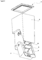
Figure 3 - is an exploded view of the grain dispenser -
Figure 4 - is an exploded view of the grain dispenser - The following numerals are assigned to different parts demonstrated in the drawings and referred to in the present detailed description of the invention:
- 1. Cooling appliance
- 2. Body
- 3. Door
- 4. Inner liner
- 5. Grain dispensing unit
- 6. Container
- 7. Dispenser
- 8. Chute
- 9. Bracket
- 10. Recess
- 11. Protrusion
- 12. Biasing means
- The present invention relates to a cooling appliance (1) comprising; a body (2), a door (3) pivotable attached to the body (2) between an open position and a closed position, wherein the body (2) and the door (3) have an inner liner (4),a grain dispensing unit (5) adapted to be detachably mounted onto the inner liner (4) comprising; a container (6) for storing the grain,
- The present invention relates to a cooling appliance (1) comprising; a dispenser (7) pivotably attached on a lower portion of the container (6), wherein the dispenser (7) is pressed by means of force applied by a user to pivot between an open position allowing the grain to flow under the influence of gravity and a closed position inhibiting flow of the grain. The cooling appliance further comprises a chute (8) provided in the dispenser (7) in communication with the container (6) to transmit the grain in the open position via an outlet on a lower portion of the container (6) and a bracket (9) partly closing the outlet onto which the chute (8) abuts in closed position. The container (6) is used as a volume to store granular foodstuff such as grain and legumes. The dispenser (7) is pivotably attached on a lower portion of the container (6). The dispenser (7) pivots between the closed position and the open position and as the name suggests, during the open position, the grain and legumes are free to flow from the container (6) towards the chute (8) provided on the dispenser (7). Likewise, during the closed position, the grain and legumes are prevented to flow through the dispenser (7) via the chute (8). The lower surface of the container (6) is in conical shape to facilitate the flow of the grain and legumes. The lower most portion of the said conical structure is covered by the chute (8) in the closed position. As the dispenser (7) is pressed by means of force applied by a user, the chute (8) moves away from the lower most portion of the said conical structure thus forming the outlet for the grain to flow. The structure of the container (6) and the chute (8) is formed such that the weight of the grain stored inside the container (6) is not sufficient enough to force the dispenser (7) to the open position. The grain dispensing unit (5) is removably attached onto the inner liner (4). The user may easily remove the grain dispensing unit (5) from the inner liner (4). The outlet is provided on a lower portion of the container (6). The chute (8) closes the outlet in the closed position of the dispenser (7). The bracket (9) is placed onto the outlet from below or from inside the container (6) so as to partly close the outlet or is placed in close vicinity of the outlet. The chute (8) abuts against the bracket (9) in the closed position. As the dispenser (7) and therefore the chute (8) moves towards the closed position, the flow rate of grain decreases. By means of the bracket (9), spillage of the grains caused by the jammed grains in-between the outlet or container (6) and the chute (8) is prevented. As a result, quality perception of the product is improved, meanwhile preventing unwanted flow of the grains to the outer environment.
- The present invention relates to a cooling appliance (1) comprising; the bracket (9) wherein the bracket (9) is elastic. The bracket (9) is produced from an elastomeric material. The elastomeric materials include but not limited to natural or synthetic rubbers, silicone, polyurethane. By means of the elastic properties the bracket (9) possesses, the flow of grain is disrupted in a smooth manner and the last grain particles are caught in between the bracket (9) and the chute (8). The grain particles temporarily deform the bracket (9) if they are caught in between the bracket (9) and the chute (8).
- The present invention relates to a cooling appliance (1) comprising; the container (6), wherein the container (6) comprises a recess (10) onto which the bracket (9) is seated via a protrusion (11) in the closed position. The container (6) comprises a pair recesses (10) on both sides and adjacent to the outlet. The bracket (9) is attached to the lower part of the container (6) via the protrusions (11). By this means, a robust assembly is achieved.
- The present invention relates to a cooling appliance (1) comprising; a biasing means (12) placed in between the dispenser (7) and the container (6) biasing the dispenser (7) towards the closed position. The biasing means (12) biases the dispenser (7) towards the closed position. The dispenser (7) is pressed by means of force applied by the user towards the open position. As the force applied by the user is removed, the biasing means (12) automatically restores the dispenser (7) towards the closed position. Therefore, ease of use is provided for the user.
- In the cooling appliance (1) of the present invention, the users are provided with a grain dispensing unit (5) having a bracket (9) preventing the spillage of the grains caused by the squeezing of the grain particles in between the container (6) and the chute (8).
Claims (4)
- A cooling appliance (1) comprising;
a body (2), a door (3) pivotable attached to the body (2) between an open position and a closed position, wherein the body (2) and the door (3) have an inner liner (4),
a grain dispensing unit (5) adapted to be detachably mounted onto the inner liner (4) comprising;
a container (6) for storing the grain,
characterized by
a dispenser (7) pivotably attached on a lower portion of the container (6), wherein the dispenser (7) is pressed by means of force applied by a user to pivot between an open position allowing the grain to flow under the influence of gravity and a closed position inhibiting flow of the grain and by a chute (8) provided in the dispenser (7) in communication with the container (6) to transmit the grain in the open position via an outlet on a lower portion of the container (6) and by a bracket (9) partly closing the outlet onto which the chute (8) abuts in closed position. - A cooling appliance (1) according to claim 1, characterized in that the bracket (9) is elastic.
- A cooling appliance (1) according to any of the preceeding claims, characterized in that the container (6) comprises a recess (10) onto which the bracket (9) is seated via a protrusion (11) in the closed position.
- A cooling appliance (1) according to any of the preceeding claims, characterized by a biasing means (12) placed in between the dispenser (7) and the container (6) biasing the dispenser (7) towards the closed position.
Applications Claiming Priority (1)
| Application Number | Priority Date | Filing Date | Title |
|---|---|---|---|
| TR2019/13427A TR201913427A2 (en) | 2019-09-05 | 2019-09-05 | A cooling appliance with a grain dispensing unit |
Publications (2)
| Publication Number | Publication Date |
|---|---|
| EP3789707A1 true EP3789707A1 (en) | 2021-03-10 |
| EP3789707B1 EP3789707B1 (en) | 2022-06-08 |
Family
ID=72292362
Family Applications (1)
| Application Number | Title | Priority Date | Filing Date |
|---|---|---|---|
| EP20193615.0A Active EP3789707B1 (en) | 2019-09-05 | 2020-08-31 | A cooling appliance with a grain dispensing unit |
Country Status (3)
| Country | Link |
|---|---|
| EP (1) | EP3789707B1 (en) |
| PL (1) | PL3789707T3 (en) |
| TR (1) | TR201913427A2 (en) |
Citations (6)
| Publication number | Priority date | Publication date | Assignee | Title |
|---|---|---|---|---|
| CH428133A (en) * | 1965-09-14 | 1967-01-15 | Wucher Karl | Container for storing and dispensing granular and powdery foods and beverages |
| JPS5118698B1 (en) | 1971-06-18 | 1976-06-11 | ||
| KR20080064052A (en) * | 2007-01-03 | 2008-07-08 | 엘지전자 주식회사 | Refrigerator |
| KR101336894B1 (en) | 2007-01-15 | 2013-12-04 | 엘지전자 주식회사 | A grain keeper for refrigerator and a refeigerator comprising the same |
| CN205860645U (en) * | 2016-06-08 | 2017-01-04 | 合肥海尔电冰箱有限公司 | Material access device and there is its refrigerator |
| CN106500445B (en) * | 2016-09-28 | 2019-03-12 | 青岛海尔股份有限公司 | Material storage device and refrigerator having the same |
-
2019
- 2019-09-05 TR TR2019/13427A patent/TR201913427A2/en unknown
-
2020
- 2020-08-31 EP EP20193615.0A patent/EP3789707B1/en active Active
- 2020-08-31 PL PL20193615.0T patent/PL3789707T3/en unknown
Patent Citations (6)
| Publication number | Priority date | Publication date | Assignee | Title |
|---|---|---|---|---|
| CH428133A (en) * | 1965-09-14 | 1967-01-15 | Wucher Karl | Container for storing and dispensing granular and powdery foods and beverages |
| JPS5118698B1 (en) | 1971-06-18 | 1976-06-11 | ||
| KR20080064052A (en) * | 2007-01-03 | 2008-07-08 | 엘지전자 주식회사 | Refrigerator |
| KR101336894B1 (en) | 2007-01-15 | 2013-12-04 | 엘지전자 주식회사 | A grain keeper for refrigerator and a refeigerator comprising the same |
| CN205860645U (en) * | 2016-06-08 | 2017-01-04 | 合肥海尔电冰箱有限公司 | Material access device and there is its refrigerator |
| CN106500445B (en) * | 2016-09-28 | 2019-03-12 | 青岛海尔股份有限公司 | Material storage device and refrigerator having the same |
Also Published As
| Publication number | Publication date |
|---|---|
| PL3789707T3 (en) | 2022-10-03 |
| TR201913427A2 (en) | 2021-03-22 |
| EP3789707B1 (en) | 2022-06-08 |
Similar Documents
| Publication | Publication Date | Title |
|---|---|---|
| US6182864B1 (en) | Bulk food dispensing apparatus | |
| US20050269366A1 (en) | Agitator assisted bulk product dispenser | |
| CA2408231C (en) | Bulk food dispensing apparatus utilizing improved lid | |
| US9549640B2 (en) | Free flow control dispenser device and method | |
| EP3542678B1 (en) | Bulk product dispenser | |
| AU2014203906B2 (en) | Expandable gravity-feed bin | |
| KR102008288B1 (en) | Spices supply | |
| CA2479113A1 (en) | Makeup device | |
| EP3789707B1 (en) | A cooling appliance with a grain dispensing unit | |
| WO2021014593A1 (en) | Beverage container | |
| AU2003222542A1 (en) | Automatic dosing device with a dosing screw and the use of such an automatic dosing device | |
| US6257464B1 (en) | Dispensing mechanism with dual function flow regulator and sealing plate | |
| EP2447186B1 (en) | Hand-held dispenser for croquettes, food articles, drugs and granular products in general | |
| WO2008067101A3 (en) | Coffee ground dispenser | |
| US589386A (en) | Half to charles j | |
| EP3945272B1 (en) | A cooling appliance having a grain dispensing unit with a locking mechanism | |
| EP3972467B1 (en) | A cooling appliance with a grain dispensing unit | |
| EP2485953A1 (en) | Liquid package cover with air duct | |
| CN222876667U (en) | Food gravity box | |
| EP3811825B1 (en) | Bulk bin device | |
| US1131558A (en) | Granary. | |
| US20100140295A1 (en) | Valve assemblies for liquid containers | |
| EP4030129A1 (en) | A cooling appliance having a water dispensing unit | |
| CA2143139A1 (en) | Bulk food dispensing system | |
| KR200354673Y1 (en) | vessel for keep the flavour |
Legal Events
| Date | Code | Title | Description |
|---|---|---|---|
| PUAI | Public reference made under article 153(3) epc to a published international application that has entered the european phase |
Free format text: ORIGINAL CODE: 0009012 |
|
| STAA | Information on the status of an ep patent application or granted ep patent |
Free format text: STATUS: REQUEST FOR EXAMINATION WAS MADE |
|
| 17P | Request for examination filed |
Effective date: 20200831 |
|
| AK | Designated contracting states |
Kind code of ref document: A1 Designated state(s): AL AT BE BG CH CY CZ DE DK EE ES FI FR GB GR HR HU IE IS IT LI LT LU LV MC MK MT NL NO PL PT RO RS SE SI SK SM TR |
|
| AX | Request for extension of the european patent |
Extension state: BA ME |
|
| REG | Reference to a national code |
Ref country code: DE Ref legal event code: R079 Ref document number: 602020003457 Country of ref document: DE Free format text: PREVIOUS MAIN CLASS: F25D0023120000 Ipc: F25D0023040000 |
|
| RIC1 | Information provided on ipc code assigned before grant |
Ipc: F25D 23/04 20060101AFI20220214BHEP |
|
| GRAP | Despatch of communication of intention to grant a patent |
Free format text: ORIGINAL CODE: EPIDOSNIGR1 |
|
| STAA | Information on the status of an ep patent application or granted ep patent |
Free format text: STATUS: GRANT OF PATENT IS INTENDED |
|
| GRAS | Grant fee paid |
Free format text: ORIGINAL CODE: EPIDOSNIGR3 |
|
| INTG | Intention to grant announced |
Effective date: 20220404 |
|
| GRAA | (expected) grant |
Free format text: ORIGINAL CODE: 0009210 |
|
| STAA | Information on the status of an ep patent application or granted ep patent |
Free format text: STATUS: THE PATENT HAS BEEN GRANTED |
|
| AK | Designated contracting states |
Kind code of ref document: B1 Designated state(s): AL AT BE BG CH CY CZ DE DK EE ES FI FR GB GR HR HU IE IS IT LI LT LU LV MC MK MT NL NO PL PT RO RS SE SI SK SM TR |
|
| REG | Reference to a national code |
Ref country code: AT Ref legal event code: REF Ref document number: 1497201 Country of ref document: AT Kind code of ref document: T Effective date: 20220615 Ref country code: CH Ref legal event code: EP |
|
| REG | Reference to a national code |
Ref country code: DE Ref legal event code: R096 Ref document number: 602020003457 Country of ref document: DE |
|
| REG | Reference to a national code |
Ref country code: IE Ref legal event code: FG4D |
|
| REG | Reference to a national code |
Ref country code: LT Ref legal event code: MG9D |
|
| REG | Reference to a national code |
Ref country code: NL Ref legal event code: MP Effective date: 20220608 |
|
| PG25 | Lapsed in a contracting state [announced via postgrant information from national office to epo] |
Ref country code: SE Free format text: LAPSE BECAUSE OF FAILURE TO SUBMIT A TRANSLATION OF THE DESCRIPTION OR TO PAY THE FEE WITHIN THE PRESCRIBED TIME-LIMIT Effective date: 20220608 Ref country code: NO Free format text: LAPSE BECAUSE OF FAILURE TO SUBMIT A TRANSLATION OF THE DESCRIPTION OR TO PAY THE FEE WITHIN THE PRESCRIBED TIME-LIMIT Effective date: 20220908 Ref country code: LT Free format text: LAPSE BECAUSE OF FAILURE TO SUBMIT A TRANSLATION OF THE DESCRIPTION OR TO PAY THE FEE WITHIN THE PRESCRIBED TIME-LIMIT Effective date: 20220608 Ref country code: HR Free format text: LAPSE BECAUSE OF FAILURE TO SUBMIT A TRANSLATION OF THE DESCRIPTION OR TO PAY THE FEE WITHIN THE PRESCRIBED TIME-LIMIT Effective date: 20220608 Ref country code: GR Free format text: LAPSE BECAUSE OF FAILURE TO SUBMIT A TRANSLATION OF THE DESCRIPTION OR TO PAY THE FEE WITHIN THE PRESCRIBED TIME-LIMIT Effective date: 20220909 Ref country code: FI Free format text: LAPSE BECAUSE OF FAILURE TO SUBMIT A TRANSLATION OF THE DESCRIPTION OR TO PAY THE FEE WITHIN THE PRESCRIBED TIME-LIMIT Effective date: 20220608 Ref country code: BG Free format text: LAPSE BECAUSE OF FAILURE TO SUBMIT A TRANSLATION OF THE DESCRIPTION OR TO PAY THE FEE WITHIN THE PRESCRIBED TIME-LIMIT Effective date: 20220908 |
|
| REG | Reference to a national code |
Ref country code: AT Ref legal event code: MK05 Ref document number: 1497201 Country of ref document: AT Kind code of ref document: T Effective date: 20220608 |
|
| PG25 | Lapsed in a contracting state [announced via postgrant information from national office to epo] |
Ref country code: RS Free format text: LAPSE BECAUSE OF FAILURE TO SUBMIT A TRANSLATION OF THE DESCRIPTION OR TO PAY THE FEE WITHIN THE PRESCRIBED TIME-LIMIT Effective date: 20220608 Ref country code: LV Free format text: LAPSE BECAUSE OF FAILURE TO SUBMIT A TRANSLATION OF THE DESCRIPTION OR TO PAY THE FEE WITHIN THE PRESCRIBED TIME-LIMIT Effective date: 20220608 |
|
| PG25 | Lapsed in a contracting state [announced via postgrant information from national office to epo] |
Ref country code: NL Free format text: LAPSE BECAUSE OF FAILURE TO SUBMIT A TRANSLATION OF THE DESCRIPTION OR TO PAY THE FEE WITHIN THE PRESCRIBED TIME-LIMIT Effective date: 20220608 |
|
| PG25 | Lapsed in a contracting state [announced via postgrant information from national office to epo] |
Ref country code: SM Free format text: LAPSE BECAUSE OF FAILURE TO SUBMIT A TRANSLATION OF THE DESCRIPTION OR TO PAY THE FEE WITHIN THE PRESCRIBED TIME-LIMIT Effective date: 20220608 Ref country code: SK Free format text: LAPSE BECAUSE OF FAILURE TO SUBMIT A TRANSLATION OF THE DESCRIPTION OR TO PAY THE FEE WITHIN THE PRESCRIBED TIME-LIMIT Effective date: 20220608 Ref country code: RO Free format text: LAPSE BECAUSE OF FAILURE TO SUBMIT A TRANSLATION OF THE DESCRIPTION OR TO PAY THE FEE WITHIN THE PRESCRIBED TIME-LIMIT Effective date: 20220608 Ref country code: PT Free format text: LAPSE BECAUSE OF FAILURE TO SUBMIT A TRANSLATION OF THE DESCRIPTION OR TO PAY THE FEE WITHIN THE PRESCRIBED TIME-LIMIT Effective date: 20221010 Ref country code: ES Free format text: LAPSE BECAUSE OF FAILURE TO SUBMIT A TRANSLATION OF THE DESCRIPTION OR TO PAY THE FEE WITHIN THE PRESCRIBED TIME-LIMIT Effective date: 20220608 Ref country code: EE Free format text: LAPSE BECAUSE OF FAILURE TO SUBMIT A TRANSLATION OF THE DESCRIPTION OR TO PAY THE FEE WITHIN THE PRESCRIBED TIME-LIMIT Effective date: 20220608 Ref country code: CZ Free format text: LAPSE BECAUSE OF FAILURE TO SUBMIT A TRANSLATION OF THE DESCRIPTION OR TO PAY THE FEE WITHIN THE PRESCRIBED TIME-LIMIT Effective date: 20220608 Ref country code: AT Free format text: LAPSE BECAUSE OF FAILURE TO SUBMIT A TRANSLATION OF THE DESCRIPTION OR TO PAY THE FEE WITHIN THE PRESCRIBED TIME-LIMIT Effective date: 20220608 |
|
| PG25 | Lapsed in a contracting state [announced via postgrant information from national office to epo] |
Ref country code: IS Free format text: LAPSE BECAUSE OF FAILURE TO SUBMIT A TRANSLATION OF THE DESCRIPTION OR TO PAY THE FEE WITHIN THE PRESCRIBED TIME-LIMIT Effective date: 20221008 |
|
| REG | Reference to a national code |
Ref country code: DE Ref legal event code: R097 Ref document number: 602020003457 Country of ref document: DE |
|
| PG25 | Lapsed in a contracting state [announced via postgrant information from national office to epo] |
Ref country code: MC Free format text: LAPSE BECAUSE OF FAILURE TO SUBMIT A TRANSLATION OF THE DESCRIPTION OR TO PAY THE FEE WITHIN THE PRESCRIBED TIME-LIMIT Effective date: 20220608 Ref country code: AL Free format text: LAPSE BECAUSE OF FAILURE TO SUBMIT A TRANSLATION OF THE DESCRIPTION OR TO PAY THE FEE WITHIN THE PRESCRIBED TIME-LIMIT Effective date: 20220608 |
|
| PLBE | No opposition filed within time limit |
Free format text: ORIGINAL CODE: 0009261 |
|
| STAA | Information on the status of an ep patent application or granted ep patent |
Free format text: STATUS: NO OPPOSITION FILED WITHIN TIME LIMIT |
|
| PG25 | Lapsed in a contracting state [announced via postgrant information from national office to epo] |
Ref country code: LU Free format text: LAPSE BECAUSE OF NON-PAYMENT OF DUE FEES Effective date: 20220831 Ref country code: DK Free format text: LAPSE BECAUSE OF FAILURE TO SUBMIT A TRANSLATION OF THE DESCRIPTION OR TO PAY THE FEE WITHIN THE PRESCRIBED TIME-LIMIT Effective date: 20220608 |
|
| REG | Reference to a national code |
Ref country code: BE Ref legal event code: MM Effective date: 20220831 |
|
| 26N | No opposition filed |
Effective date: 20230310 |
|
| PG25 | Lapsed in a contracting state [announced via postgrant information from national office to epo] |
Ref country code: SI Free format text: LAPSE BECAUSE OF FAILURE TO SUBMIT A TRANSLATION OF THE DESCRIPTION OR TO PAY THE FEE WITHIN THE PRESCRIBED TIME-LIMIT Effective date: 20220608 |
|
| PG25 | Lapsed in a contracting state [announced via postgrant information from national office to epo] |
Ref country code: IE Free format text: LAPSE BECAUSE OF NON-PAYMENT OF DUE FEES Effective date: 20220831 Ref country code: FR Free format text: LAPSE BECAUSE OF NON-PAYMENT OF DUE FEES Effective date: 20220831 |
|
| PG25 | Lapsed in a contracting state [announced via postgrant information from national office to epo] |
Ref country code: BE Free format text: LAPSE BECAUSE OF NON-PAYMENT OF DUE FEES Effective date: 20220831 |
|
| PG25 | Lapsed in a contracting state [announced via postgrant information from national office to epo] |
Ref country code: IT Free format text: LAPSE BECAUSE OF FAILURE TO SUBMIT A TRANSLATION OF THE DESCRIPTION OR TO PAY THE FEE WITHIN THE PRESCRIBED TIME-LIMIT Effective date: 20220608 |
|
| REG | Reference to a national code |
Ref country code: CH Ref legal event code: PL |
|
| PG25 | Lapsed in a contracting state [announced via postgrant information from national office to epo] |
Ref country code: CY Free format text: LAPSE BECAUSE OF FAILURE TO SUBMIT A TRANSLATION OF THE DESCRIPTION OR TO PAY THE FEE WITHIN THE PRESCRIBED TIME-LIMIT Effective date: 20220608 Ref country code: CH Free format text: LAPSE BECAUSE OF NON-PAYMENT OF DUE FEES Effective date: 20230831 |
|
| PG25 | Lapsed in a contracting state [announced via postgrant information from national office to epo] |
Ref country code: MK Free format text: LAPSE BECAUSE OF FAILURE TO SUBMIT A TRANSLATION OF THE DESCRIPTION OR TO PAY THE FEE WITHIN THE PRESCRIBED TIME-LIMIT Effective date: 20220608 Ref country code: HU Free format text: LAPSE BECAUSE OF FAILURE TO SUBMIT A TRANSLATION OF THE DESCRIPTION OR TO PAY THE FEE WITHIN THE PRESCRIBED TIME-LIMIT; INVALID AB INITIO Effective date: 20200831 |
|
| PG25 | Lapsed in a contracting state [announced via postgrant information from national office to epo] |
Ref country code: MT Free format text: LAPSE BECAUSE OF FAILURE TO SUBMIT A TRANSLATION OF THE DESCRIPTION OR TO PAY THE FEE WITHIN THE PRESCRIBED TIME-LIMIT Effective date: 20220608 |
|
| PG25 | Lapsed in a contracting state [announced via postgrant information from national office to epo] |
Ref country code: BG Free format text: LAPSE BECAUSE OF FAILURE TO SUBMIT A TRANSLATION OF THE DESCRIPTION OR TO PAY THE FEE WITHIN THE PRESCRIBED TIME-LIMIT Effective date: 20220608 |
|
| PG25 | Lapsed in a contracting state [announced via postgrant information from national office to epo] |
Ref country code: BG Free format text: LAPSE BECAUSE OF FAILURE TO SUBMIT A TRANSLATION OF THE DESCRIPTION OR TO PAY THE FEE WITHIN THE PRESCRIBED TIME-LIMIT Effective date: 20220608 |
|
| PGFP | Annual fee paid to national office [announced via postgrant information from national office to epo] |
Ref country code: DE Payment date: 20250820 Year of fee payment: 6 |
|
| PGFP | Annual fee paid to national office [announced via postgrant information from national office to epo] |
Ref country code: TR Payment date: 20250825 Year of fee payment: 6 Ref country code: PL Payment date: 20250821 Year of fee payment: 6 |
|
| PGFP | Annual fee paid to national office [announced via postgrant information from national office to epo] |
Ref country code: GB Payment date: 20250820 Year of fee payment: 6 |
|
| PG25 | Lapsed in a contracting state [announced via postgrant information from national office to epo] |
Ref country code: CH Free format text: THE PATENT HAS BEEN ANNULLED BY A DECISION OF A NATIONAL AUTHORITY Effective date: 20230831 |