EP3789705A1 - A mounting tool for a connection system of a door of a built-in domestic appliance to a door of a furniture - Google Patents
A mounting tool for a connection system of a door of a built-in domestic appliance to a door of a furniture Download PDFInfo
- Publication number
- EP3789705A1 EP3789705A1 EP19195603.6A EP19195603A EP3789705A1 EP 3789705 A1 EP3789705 A1 EP 3789705A1 EP 19195603 A EP19195603 A EP 19195603A EP 3789705 A1 EP3789705 A1 EP 3789705A1
- Authority
- EP
- European Patent Office
- Prior art keywords
- door
- guide profile
- sled
- furniture
- mounting tool
- Prior art date
- Legal status (The legal status is an assumption and is not a legal conclusion. Google has not performed a legal analysis and makes no representation as to the accuracy of the status listed.)
- Granted
Links
Images







Classifications
-
- F—MECHANICAL ENGINEERING; LIGHTING; HEATING; WEAPONS; BLASTING
- F25—REFRIGERATION OR COOLING; COMBINED HEATING AND REFRIGERATION SYSTEMS; HEAT PUMP SYSTEMS; MANUFACTURE OR STORAGE OF ICE; LIQUEFACTION SOLIDIFICATION OF GASES
- F25D—REFRIGERATORS; COLD ROOMS; ICE-BOXES; COOLING OR FREEZING APPARATUS NOT OTHERWISE PROVIDED FOR
- F25D23/00—General constructional features
- F25D23/10—Arrangements for mounting in particular locations, e.g. for built-in type, for corner type
-
- A—HUMAN NECESSITIES
- A47—FURNITURE; DOMESTIC ARTICLES OR APPLIANCES; COFFEE MILLS; SPICE MILLS; SUCTION CLEANERS IN GENERAL
- A47B—TABLES; DESKS; OFFICE FURNITURE; CABINETS; DRAWERS; GENERAL DETAILS OF FURNITURE
- A47B96/00—Details of cabinets, racks or shelf units not covered by a single one of groups A47B43/00 - A47B95/00; General details of furniture
- A47B96/20—Furniture panels or like furniture elements
- A47B2096/208—Decorative panels for household appliances
-
- E—FIXED CONSTRUCTIONS
- E05—LOCKS; KEYS; WINDOW OR DOOR FITTINGS; SAFES
- E05D—HINGES OR SUSPENSION DEVICES FOR DOORS, WINDOWS OR WINGS
- E05D11/00—Additional features or accessories of hinges
- E05D11/0009—Templates for marking the position of fittings on wings or frames
-
- E—FIXED CONSTRUCTIONS
- E05—LOCKS; KEYS; WINDOW OR DOOR FITTINGS; SAFES
- E05Y—INDEXING SCHEME ASSOCIATED WITH SUBCLASSES E05D AND E05F, RELATING TO CONSTRUCTION ELEMENTS, ELECTRIC CONTROL, POWER SUPPLY, POWER SIGNAL OR TRANSMISSION, USER INTERFACES, MOUNTING OR COUPLING, DETAILS, ACCESSORIES, AUXILIARY OPERATIONS NOT OTHERWISE PROVIDED FOR, APPLICATION THEREOF
- E05Y2201/00—Constructional elements; Accessories therefor
- E05Y2201/60—Suspension or transmission members; Accessories therefor
- E05Y2201/622—Suspension or transmission members elements
- E05Y2201/708—Sliders
-
- E—FIXED CONSTRUCTIONS
- E05—LOCKS; KEYS; WINDOW OR DOOR FITTINGS; SAFES
- E05Y—INDEXING SCHEME ASSOCIATED WITH SUBCLASSES E05D AND E05F, RELATING TO CONSTRUCTION ELEMENTS, ELECTRIC CONTROL, POWER SUPPLY, POWER SIGNAL OR TRANSMISSION, USER INTERFACES, MOUNTING OR COUPLING, DETAILS, ACCESSORIES, AUXILIARY OPERATIONS NOT OTHERWISE PROVIDED FOR, APPLICATION THEREOF
- E05Y2600/00—Mounting or coupling arrangements for elements provided for in this subclass
- E05Y2600/50—Mounting methods; Positioning
- E05Y2600/56—Positioning, e.g. re-positioning, or pre-mounting
-
- E—FIXED CONSTRUCTIONS
- E05—LOCKS; KEYS; WINDOW OR DOOR FITTINGS; SAFES
- E05Y—INDEXING SCHEME ASSOCIATED WITH SUBCLASSES E05D AND E05F, RELATING TO CONSTRUCTION ELEMENTS, ELECTRIC CONTROL, POWER SUPPLY, POWER SIGNAL OR TRANSMISSION, USER INTERFACES, MOUNTING OR COUPLING, DETAILS, ACCESSORIES, AUXILIARY OPERATIONS NOT OTHERWISE PROVIDED FOR, APPLICATION THEREOF
- E05Y2600/00—Mounting or coupling arrangements for elements provided for in this subclass
- E05Y2600/50—Mounting methods; Positioning
- E05Y2600/56—Positioning, e.g. re-positioning, or pre-mounting
- E05Y2600/58—Positioning, e.g. re-positioning, or pre-mounting by using indicators or markings, e.g. scales
-
- E—FIXED CONSTRUCTIONS
- E05—LOCKS; KEYS; WINDOW OR DOOR FITTINGS; SAFES
- E05Y—INDEXING SCHEME ASSOCIATED WITH SUBCLASSES E05D AND E05F, RELATING TO CONSTRUCTION ELEMENTS, ELECTRIC CONTROL, POWER SUPPLY, POWER SIGNAL OR TRANSMISSION, USER INTERFACES, MOUNTING OR COUPLING, DETAILS, ACCESSORIES, AUXILIARY OPERATIONS NOT OTHERWISE PROVIDED FOR, APPLICATION THEREOF
- E05Y2800/00—Details, accessories and auxiliary operations not otherwise provided for
- E05Y2800/69—Permanence of use
- E05Y2800/692—Temporary use, e.g. removable tools
-
- E—FIXED CONSTRUCTIONS
- E05—LOCKS; KEYS; WINDOW OR DOOR FITTINGS; SAFES
- E05Y—INDEXING SCHEME ASSOCIATED WITH SUBCLASSES E05D AND E05F, RELATING TO CONSTRUCTION ELEMENTS, ELECTRIC CONTROL, POWER SUPPLY, POWER SIGNAL OR TRANSMISSION, USER INTERFACES, MOUNTING OR COUPLING, DETAILS, ACCESSORIES, AUXILIARY OPERATIONS NOT OTHERWISE PROVIDED FOR, APPLICATION THEREOF
- E05Y2900/00—Application of doors, windows, wings or fittings thereof
- E05Y2900/20—Application of doors, windows, wings or fittings thereof for furniture, e.g. cabinets
-
- E—FIXED CONSTRUCTIONS
- E05—LOCKS; KEYS; WINDOW OR DOOR FITTINGS; SAFES
- E05Y—INDEXING SCHEME ASSOCIATED WITH SUBCLASSES E05D AND E05F, RELATING TO CONSTRUCTION ELEMENTS, ELECTRIC CONTROL, POWER SUPPLY, POWER SIGNAL OR TRANSMISSION, USER INTERFACES, MOUNTING OR COUPLING, DETAILS, ACCESSORIES, AUXILIARY OPERATIONS NOT OTHERWISE PROVIDED FOR, APPLICATION THEREOF
- E05Y2900/00—Application of doors, windows, wings or fittings thereof
- E05Y2900/30—Application of doors, windows, wings or fittings thereof for domestic appliances
- E05Y2900/31—Application of doors, windows, wings or fittings thereof for domestic appliances for refrigerators
-
- F—MECHANICAL ENGINEERING; LIGHTING; HEATING; WEAPONS; BLASTING
- F25—REFRIGERATION OR COOLING; COMBINED HEATING AND REFRIGERATION SYSTEMS; HEAT PUMP SYSTEMS; MANUFACTURE OR STORAGE OF ICE; LIQUEFACTION SOLIDIFICATION OF GASES
- F25D—REFRIGERATORS; COLD ROOMS; ICE-BOXES; COOLING OR FREEZING APPARATUS NOT OTHERWISE PROVIDED FOR
- F25D23/00—General constructional features
- F25D23/02—Doors; Covers
- F25D23/028—Details
-
- F—MECHANICAL ENGINEERING; LIGHTING; HEATING; WEAPONS; BLASTING
- F25—REFRIGERATION OR COOLING; COMBINED HEATING AND REFRIGERATION SYSTEMS; HEAT PUMP SYSTEMS; MANUFACTURE OR STORAGE OF ICE; LIQUEFACTION SOLIDIFICATION OF GASES
- F25D—REFRIGERATORS; COLD ROOMS; ICE-BOXES; COOLING OR FREEZING APPARATUS NOT OTHERWISE PROVIDED FOR
- F25D2323/00—General constructional features not provided for in other groups of this subclass
- F25D2323/02—Details of doors or covers not otherwise covered
Definitions
- the present invention relates to a mounting tool for a connecting system of a door of a built-in appliance to a door of a furniture, inside which the built-in appliance is fixed.
- the present invention finds advantageous application in the connection of a door of a built-in refrigerator to a door of kitchen furniture, to which the following treatment will make explicit reference without losing its generality.
- a built-in refrigerator i.e. a refrigerator intended to be fixed inside a kitchen furniture
- an installer must fix (typically by means of screw fixing systems) the built-in refrigerator to the kitchen furniture and then he must connect the door of the built-in refrigerator to the door of the kitchen furniture so as to make possible the simultaneous opening of the door of the built-in refrigerator and of the door of the kitchen furniture.
- a known sliding connection system comprises a sled (typically with a "C"-shaped cross section) intended to be fixed to an edge of the door of the built-in refrigerator and a guide profile (typically with a "T"-shaped cross section) intended to be fixed to the door of the kitchen furniture, after having slidably coupled the sled to the guide profile, so that the sliding of the sled along the guide profile allows to open and close simultaneously the door of the kitchen furniture and the door of the built-in refrigerator.
- a sled typically with a "C"-shaped cross section
- a guide profile typically with a "T"-shaped cross section
- the installer To mount the sliding connection system, the installer must fix the sled to an edge of the door of the built-in refrigerator (typically by means of one or two screws), then he must couple the sled to the guide profile and finally he must fix, typically by means of a plurality of screws, the guide profile to the door of the furniture in a determined fixing position.
- the guide profile In detail, in this determined fixing position, the guide profile must be perfectly aligned with the sled along an horizontal direction (i.e. along a direction orthogonal to the rotation axis about which the door of the furniture rotates during its opening and/or closing) so as to allow the sliding of the sled along the guide profile minimizing the mutual friction between the sled and the guide profile.
- the guide profile must be placed in a position such that to prevent the sled to uncouple from the guide profile at the time of maximum opening of the door of the furniture, or maximum closure of the door of the furniture, causing, in this way, the disconnection of the door of the built-in refrigerator from the door of the furniture.
- connection of the door of a built-in refrigerator to the door of a furniture is a complex operation and it involves the execution of a series of measurements in order to identify the correct fixing position of the guide profile.
- connection systems and methods require a certain amount of experience and practicality in the execution of the operations described above in order to correctly connect the door of the built-in refrigerator to the door of the furniture. Therefore, to connect a door of a built-in refrigerator to a door of a furniture it is necessary to have a good dose of manual skills or it is necessary the assistance of a skilled operator, with a consequent cost increase.
- the object of the present invention is to provide a mounting tool for a connecting system of a door of a built-in domestic appliance to a door of furniture which is free from the drawbacks described above and and which, in particular, allow to simplify and speed up the connection of the door of a built-in domestic appliance to the door of a furniture.
- a mounting tool for a connection system of a door of a built-in domestic appliance to a door of a furniture a connection system of a door of a built-in domestic appliance to a door of a furniture by means of said mounting tool and a connection method of a door of a built-in domestic appliance to a door of a furniture by means of said mounting tool, in accordance with what is described in the attached claims.
- the mounting tool is configured to removably couple to the sled and to the guide profile and it comprises:
- the mounting tool allows the identification of the fixing position of the guide profile, that is to say the identification of that position in which the guide profile is at the correct distance from the edge of the door of the furniture and, at the same time, it is positioned with respect to the sled so as to allow the sled to slide along the guide profile (during the opening and closing of the door of the furniture) without losing contact with the guide profile itself and assuring at the same time the due alignment between the sled and the guide profile minimizing the mutual sliding friction.
- the main body is designed to allow, when the at least a portion of the guide profile is housed in the seat, the installation of a fixing device suitable to fix the guide profile to the door of the furniture.
- the fixing device comprises at least a screw; the guide profile comprises at least a first through hole designed to receive the screw; and the main body comprises at least at least a second through hole arranged so as to be aligned with the first through hole when the at least a portion of the guide profile is housed in the seat on the predetermined position.
- the main body comprises a tubular invitation element which protrudes from the main body and is arranged around the second through hole.
- this tubular invitation elements facilitates the correct insertion of the at least a screw through the mounting tool and the guide profile.
- the tubular invitation element comprises:
- the first flaps are arranged along a first circular profile at an edge of the second through hole spaced from each other so as to define a series of slits between adjacent first flaps; and the second flaps are arranged along a second circular profile concentric and larger than the first circular profile and each in front of a respective slit so as to allow the first flaps to be bent outward of the second through hole when the screw is inserted in the second through hole and the head of the screw contacts the first flaps.
- the reference plate extends orthogonally to the main body on the opposite side with respect to the coupling plate, giving to the mounting tool a "Z" shape.
- the coupling plate has an edge which is arranged perpendicularly to the coupling plate, protrudes from the coupling plate from the side opposite to the main body, and is designed to embrace the sled when the coupling plate is coupled to the sled.
- the edge extends on three sides of the coupling plate leaving free the side facing the door of the furniture.
- the mounting tool comprises a snap-on fixing system for establishing a connection between the coupling plate and the sled.
- the snap-on fixing system comprises:
- the seat of the main body has an open end through which the at least a portion of the guide profile can be slidably inserted into said seat, and has a closed end against which an edge of the guide profile abuts, on the predetermined position.
- the reference plate comprises an edge which is arranged perpendicularly to the reference plate, protrudes from the reference plate from the same side of the main body, and is designed to embrace at least partially the door of the furniture.
- the reference plate comprises a through opening designed to receive a hinged cover of the guide profile, when the at least a portion of the guide profile is housed in the seat.
- connection system comprises:
- connection method of a door of a built-in domestic appliance to a door of a furniture comprises the steps of:
- the sled is fixed to the outer edge of the door of the built-in domestic appliance before coupling the sled to the mounting tool.
- the guide profile is coupled to the sled after coupling the mounting tool to the guide profile.
- the step of coupling the mounting tool to the guide profile involves inserting the hinged cover of the guide profile in the through opening formed in the reference plate of the mounting tool.
- the number 1 indicates as whole a mounting tool to connect a door 2 of a built-in refrigerator 3 to a door 4 of a kitchen furniture 5.
- the furniture 5 has a wall 6, a wall 7 which is parallel and opposite to the wall 6, and a door 4 which is hinged to the wall 7; and the built-in refrigerator 3 has a wall 8, a wall 9 which is parallel and opposite to the wall 8, and a door 2 which is hinged to the wall 9.
- the two walls 6 and 7 of the furniture 5 are preferably, fixed, respectively, to the walls 8 and 9 of the built-in refrigerator 3 by means of known fixing techniques (typically with screw fastening systems), and the door 4 of the furniture 5 is connected to the door 2 of the built-in refrigerator 3 by means of a sliding connection system 10.
- the sliding connection system 10 is designed to allow to open simultaneous the door 2 of the built-in refrigerator 3 together with the door 4 of the furniture 5, despite the door 4 being rotatably mounted (hinged) around a rotation axis X and the door 2 is rotatably mounted (hinged) around another rotation axis (not visible in the attached figures) which is arranged offset with respect to the rotation axis X.
- the sliding connection system 10 illustrated in the attached figures comprises a guide profile 11 which is designed to be fixed to the door 4 of the furniture 5 oriented orthogonally to the rotation axis X of the door 4, and a sled 12 which is designed to be fixed to an outer edge 13 of the door 2 of the built-in refrigerator 3 and to slidably couple to the guide profile 11 so that, when the guide profile 11 is fixed to the door 4 of the furniture 5 and the sled 12 is fixed to the outer edge 13 of the door 2 of the built-in refrigerator 3 and is coupled to the guide profile 11, the sliding of the sled 12 along the guide profile 11 induces the opening of the door 2 of the built-in refrigerator 3 following the opening of the door 4 of the furniture piece 5.
- the guide profile 11 has a "T" shaped cross section and the sled 12 has a "C” shaped cross section to envelop the wings of the "T" section of the guide profile 11.
- any other configuration of the sled 12 and/or of the guide profile 11 which allow, in use (i.e. when the guide profile 11 is fixed to the door 4 and the sled 12 is fixed to the door 2), a sliding coupling between the sled 12 and the guide profile 11 could be provided.
- connection system 10 further comprises the mounting tool 1 which can be removably coupled to the guide profile 11 (as shown, for example, in figures 3 and 4 ) and to the sled 12 (as shown, for example, in figure 5 ).
- the mounting tool 1 comprises a coupling plate 14 to allow the removable coupling of the mounting tool 1 with the sled 12 and a main body 15 to allow the removable coupling of the mounting tool 1 with the guide profile 11.
- the mounting tool 1 further comprises a reference plate 16 which is designed to abut against an outer edge 17 of the door 4 of the furniture 5 (as shown in figures 8 and 9 ) so as to define a fixing position of the guide profile 11 to the door 4 of the furniture 5.
- the mounting tool 1 when the mounting tool 1 is coupled to the sled 12 and to the guide profile 11 (i.e. when the coupling plate 14 is coupled to the sled 12 and the main body 15 is coupled to the guide profile 11), the guide profile 11 is placed in contact the door 4 of the furniture 5, and the sled 12 is at least opportunely placed (preferably fixed) to the edge 13 of the door 2 of the built-in refrigerator 3 (in a condition in which the sled 12 is slidably coupled to the guide profile 11), the mounting tool 1 allows the identification of the fixing position of the guide profile 11, that is to say the identification of that position in which the guide profile 11 is at the correct distance from the edge 17 of the door 4 of the furniture 5 and, at the same time, it is positioned with respect to the sled 12 so as to allow the sled 12 to slide along the guide profile 11 (during the opening and closing of the door 4 of the furniture 5) without losing contact with the guide profile 11 itself.
- the coupling plate 14 is perpendicular to the main body 15 and is arranged at an inner end 15a of the main body 15, and the reference plate 16 which is perpendicular to the main body 15, is arranged at an outer end 15b of the main body 15 and extends orthogonally to the main body 15 on the opposite side with respect to the coupling plate 14, thus giving the mounting tool 1 a "Z" shape.
- the reference plate 16 is angularly placed with respect to the main body 15 so as to abut against at least part of the outer edge 17 of the door 4 of the furniture piece 5.
- the coupling plate 14 is angularly placed with respect to the main body 15.
- the main body 15 is provided with a seat 18 which is designed to house at least a portion of the guide profile 11 in a predetermined position.
- the seat 18 has a closed end 18a against which, in use (i.e.
- the aforementioned predetermined position of the at least a portion of the guide profile 11 inside the seat 18 is the position in which the edge 19 of the guide profile 11 abuts against the closed end 18a of the seat 18 so as to arrest the sliding of the guide profile 11 with respect to the mounting tool 1.
- the reference plate 16 comprises an edge 20 which is arranged perpendicularly to the reference plate 16, protrudes from the reference plate 16 from the same side of the main body 15, and is designed to embrace at least partially the outer edge 17 of the door 4 of the furniture 5, when the at least a portion of the guide profile 11 is housed in the seat 18 in the predetermined position, the coupling plate 14 is coupled to the sled 12, and the sled 12 is at least properly positioned (preferably already fixed) to the outer edge 13 of the door 2 of the refrigerator 3.
- the reference plate 16 defines the fixing position of the guide profile 11, that is the correct position of the guide profile 11 with respect to the edge 17 of the door 4 of the furniture 5 that with respect to the sled 12.
- the seat 18 is designed to allow, preferably by means of a fixing device 21, the fixing of the guide profile 11 to the door 4 of the furniture 5, once the above-described fixing position of the guide profile 11 has been defined.
- the fixing device 21 (comprises) consists of two screws 21a, preferably self-threading, intended to be inserted through the mounting tool 1, the guide profile 11, and the door 4 of the furniture 5 thus fixing the guide profile 11 to the door 4 itself.
- the guide profile 11 comprises a plurality of through holes 22, each designed to receive a screw 21a and the mounting tool 1 comprises a plurality of through holes 23, each designed to receive a respective screw 21a and each arranged so as to result aligned with a respective through hole 22, when the mounting tool 1 is coupled to the guide profile 11 in the predetermined position (i.e. when the at least a portion of the guide profile 11 is housed in the seat 18 in the predetermined position) as shown, in particular, in figures 3, 5 , 8 and 9 .
- the fixing device 21 (comprises) consists of only one screw 21a
- the guide profile 11 comprises only one through hole, similar to the through holes 22 described above and, designed to receive the one screw 21a
- the mounting tool 1 comprises only one through hole which is similar to the through holes 23 described above and is arranged so as to result aligned with the one through hole of the guide profile 11, when the mounting tool 1 is coupled to the guide profile 11 in the predetermined position.
- the main body 15 further comprises a series of tubular invitation elements 24, which protrudes from the main body 15 and are arranged around a respective through hole 23.
- this tubular invitation elements 24 facilitates the correct insertion of the screw 21a through the mounting tool 1 and the guide profile 11.
- each tubular invitation element 24 comprises a plurality of flaps 25 arranged around the respective through hole 23 so as to guide a stem 26 of the screw 21a, when the screw 21a is inserted in the through hole 23, and a plurality of flaps 27 arranged around the through hole 23 outside of the flaps 25 so as to guide a head 28 of the screw 21a, when the screw 21a is inserted in the through hole 23.
- the flaps 25 are arranged along a circular profile 29 at an edge (not visible in the attached figures) of the through hole 23 spaced from one another so that between adjacent flaps 25 a series of slits 30 are defined.
- the flaps 27 are arranged at these slits 30 so as to allow the flaps 25 to be bent outward of the through hole 23 when the screw 21a is inserted in the through hole 23 and the head 28 of the screw 21a contacts the first flaps 25 of (as illustrated by the arrows shown in figure 9A-9B ).
- the circular profile 29 along which the flaps 25 are arranged has, indeed, a diameter approximately equal (with clearance) to the external diameter of the stem 26 of the screw 21a so as to envelop the stem 26 while the screw 21a is inserted inside the through hole 23 and to guide the screw 21a during its advancement.
- the risk of an incorrect placement of the guide profile 11 because of an incorrect insertion of one or more screws 21a in the door 4 of the furniture 5, which would compromise the correct connection between door 2 of the refrigerator 3 and door 4 of the furniture 5, is minimized.
- the flaps 27 are arranged along a further circular profile 31 which is concentric with the circular profile 29 and has a diameter greater than that of the circular profile 29.
- the diameter of the circular profile 31 is approximately equal (with clearance) to the outer diameter of the head 28 of the screw 21a so as to envelop the head 28, when the screw 21a is inserted inside the through hole 23 (thus inside the tubular invitation element 24, if present) so as to guide the screw 21a during its advancement and to guarantee (together with the first flaps 25) the correct placement of the screw 21a and therefore of the guide profile 11.
- the tubular invitation element 24 comprises only a plurality of flaps 27 arranged around the through hole 23, preferably spaced from each other, along a circular profile 31 having a diameter approximately equal (with clearance) to the outer diameter of the head 28 of the screw 21a so as to guide the head 28 of the screw 21a, and thus the screw 21a, when the screw 21a is inserted in the through hole 23 so as to ensure the correct placement of the screw 21a and then the guide profile 11.
- the guide profile 11 further comprises a cover 32 hinged to the guide profile 11 at the edge 19 of this guide profile 11 and designed to cover the through holes 22 provided on the guide profile 11 and the screws 21a inserted in said through holes 22.
- the reference plate 16 comprises a through opening 33 designed to receive the hinged cover 32 so as to allow passage through the mounting tool 1 of the cover 32, when the cover 32 is in the open configuration (i.e. is angularly arranged with respect to the guide profile 11 so as to leave exposed the through holes 22 provided on the guide profile 11) and the at least one portion of the guide profile 11 is housed in the seat 18 in the predetermined position.
- the cover 32 allows to cover the screws 21a and the through holes 22, after having fixed the guide profile 11 to the door 4 of the furniture 5 and after having uncoupled the mounting tool 1 from the guide profile 11 and from the sled 12.
- the fixing device 21 consists of (comprises) an adhesive fixing element which has two parallel and opposite adhesive surfaces, one typically glued from the beginning to the guide profile 11 and the other intended to be glued to the door 4 of the furniture 5, and a removable protective film to initially cover the adhesive surface intended to be fixed to the door 4 of the furniture 5.
- an adhesive fixing element which has two parallel and opposite adhesive surfaces, one typically glued from the beginning to the guide profile 11 and the other intended to be glued to the door 4 of the furniture 5, and a removable protective film to initially cover the adhesive surface intended to be fixed to the door 4 of the furniture 5.
- the guide profile 11 can be fixed to the door 4 of the furniture 5 by removing the protective film, for example by means of a graspable removal flap arranged to protrude outwardly from the guide profile 11.
- the fixing device 21 could consist of (or comprise) one or more rivets intended to be inserted in respective through holes opportunely made on the guide profile 11 so as to fix the guide profile 11 to the door 4 of the furniture 5 in the above mentioned fixing position.
- the main body 15 of the mounting tool 1 could comprise a series of references designed to indicate, when the mounting tool 1 is coupled to the guide profile 11 in the predetermined position, the position at which said one or more through holes must be made.
- the main body 15 could comprise a series of through openings (optionally each provided with an invitation element similar to the tubular invitations 24 described above) configured to leave exposed the area of the guide profile 11 at which the aforementioned through holes must be made.
- the mounting tool 1 comprises a snap-on fixing system 34 for establishing a connection between the coupling plate 14 and the sled 12.
- the coupling plate 14 has an edge 35 which is arranged perpendicularly to the coupling plate 14 on the side opposite the main body 15, protrudes from the coupling plate 14 and it is designed to embrace the sled 12 when the coupling plate 14 is coupled to the sled 12.
- the edge 35 extends on three sides of the coupling plate 14 leaving free the side facing the door 4 of the furniture 5.
- the snap-on fixing system 34 preferably comprises two recesses 36 (shown in particular in figures 2 , 7 , 10 and 11 ) formed on two edges 37 of the sled 12, preferably parallel to each other, and preferably oriented along the thickness of the door 2, when the sled 12 is fixed to the door 2, and two teeth 38 (shown in particular in figures 2 , 5 , 6 , 7 , 8 , 9 and 10 ) which are provided on / borne by the coupling plate 14 and are shaped to insert into the two recesses 36 of the sled 12, when the mounting tool 1 is coupled to the sled 12.
- connection method can be implemented using the connection system 10 described above, and in particular using the mounting tool 1 described above.
- the installer to correctly connect the door 2 of the built-in refrigerator 3 to the door 4 of the furniture 5, the installer, after having placed within and appropriately fixed the built-in refrigerator 3 inside the furniture 5, couples the mounting tool 1 to the guide profile 11, as shown in figure 3, 5 , 6 . Subsequently, after having fixed (with known methods) the sled 12 to the edge 13 of the door 2 of the built-in refrigerator 3, the installer connects the guide profile 11 to the sled 12, for example, by inserting a protruding portion 39 of the guide profile 11 (i.e.
- the installer places the mounting tool 1 (coupled with the sled 12 and with the guide profile 11) on an inner surface 40 of the door 4 of the furniture 5 in a position such that the reference plate 16 abuts against the outer edge 17 of the door 4 of the furniture 5, as shown in figure 8 , so as to define the above-described fixing position and immediately afterwards the installer fixes the guide profile 11 to the door 4 of the furniture 5, preferably by screwing the screws 21a, as described above and shown in figure 9 . Finally, the installer decouples the mounting tool 1 from the guide profile 11 and from the sled 12, as shown in figure 10 , by pulling the mounting tool 1 and/or by sliding the mounting tool 1 along the guide profile 11 away from the sled 12.
- the installer preferably, after having removed the mounting tool 1, closes the cover 32 to cover the fixing screws 21a.
- the installer after having placed within and opportunely fixed the built-in refrigerator 3 inside the furniture 5, couples the mounting tool 1 to both the guide profile 11 and the sled 12, then he places the sled 12 (coupled with the mounting tool 1) in contact with the outer edge 13 of the door 2 of the built-in refrigerator 3 and, keeping in position the sled 12, places the mounting tool 1 (coupled with the sled 12 and with the guide profile 11) to the inner surface 40 of the door 4 of the furniture 5 and rotates the door 2 of the built-in refrigerator 3 and the door 4 of the furniture 5 so that the reference plate 16 abuts against the outer edge 17 of the door 4 of the furniture 5 so as to define the fixing position of the guide profile 11, as described above, then he fixes the guide profile 11 to the door 4 of the furniture 5 and the sled 12 to the outer edge 13 of the door 2 of the built-in refrigerator 3.
- the sled 12 can be fixed to the edge 13 of the door 2 of the built-in refrigerator 3 by means of a screw 41 (as shown in figures 2 , 7 , 10 , 11 and 12 ).
- the reference plate 16 could be provided with a further through hole, similar to the through holes 23, and designed to receive the screw 41 so as to fix the sled 12 to the outer edge 13 of the door 2 of the built-in refrigerator 3, once the fixing position of the guide profile 11 has been defined.
- the mounting tool 1, and the connection method and connection system 10 described above have numerous advantages.
- the mounting tool 1 described above allows the connection of the door 2 of the built- in refrigerator 3 to the door 4 of the furniture 5 in a quickly and easy manner. Indeed, thanks to the use of the mounting tool 1 the identification of the fixing position of the guide profile 11 can be carry out simply coupling the mounting tool 1 to the sled 12 and to the guide profile 11 and then opportunely rotating the door 2 and the door 4 until the reference plate 16 abuts against at least part of the edge 17 of the door 4 of the furniture 5, without carrying out several measurements as in the prior art. This allows, at the same time, to reduce the risk of error during the installation of the connection system 10.
- connection method described above can be easily performed even by an unskilled user.
- the mounting tool 1 is easy and inexpensive to manufacture and can be used several times, for different mounting operations.
Landscapes
- Engineering & Computer Science (AREA)
- Chemical & Material Sciences (AREA)
- Combustion & Propulsion (AREA)
- Physics & Mathematics (AREA)
- Mechanical Engineering (AREA)
- Thermal Sciences (AREA)
- General Engineering & Computer Science (AREA)
- Hinges (AREA)
Abstract
Description
- The present invention relates to a mounting tool for a connecting system of a door of a built-in appliance to a door of a furniture, inside which the built-in appliance is fixed.
- The present invention finds advantageous application in the connection of a door of a built-in refrigerator to a door of kitchen furniture, to which the following treatment will make explicit reference without losing its generality.
- Nowadays, to mount a built-in refrigerator (i.e. a refrigerator intended to be fixed inside a kitchen furniture) inside a kitchen furniture, after properly placing the built-in refrigerator inside the kitchen furniture, an installer must fix (typically by means of screw fixing systems) the built-in refrigerator to the kitchen furniture and then he must connect the door of the built-in refrigerator to the door of the kitchen furniture so as to make possible the simultaneous opening of the door of the built-in refrigerator and of the door of the kitchen furniture.
- In detail, the installer must fix two parallel and opposite walls of the built-in refrigerator to two parallel and opposite walls of the kitchen furniture and then he must connect the door of the built-in refrigerator to the door of the kitchen furniture by means a sliding connection system. A known sliding connection system comprises a sled (typically with a "C"-shaped cross section) intended to be fixed to an edge of the door of the built-in refrigerator and a guide profile (typically with a "T"-shaped cross section) intended to be fixed to the door of the kitchen furniture, after having slidably coupled the sled to the guide profile, so that the sliding of the sled along the guide profile allows to open and close simultaneously the door of the kitchen furniture and the door of the built-in refrigerator.
- To mount the sliding connection system, the installer must fix the sled to an edge of the door of the built-in refrigerator (typically by means of one or two screws), then he must couple the sled to the guide profile and finally he must fix, typically by means of a plurality of screws, the guide profile to the door of the furniture in a determined fixing position. In detail, in this determined fixing position, the guide profile must be perfectly aligned with the sled along an horizontal direction (i.e. along a direction orthogonal to the rotation axis about which the door of the furniture rotates during its opening and/or closing) so as to allow the sliding of the sled along the guide profile minimizing the mutual friction between the sled and the guide profile. At the same time, the guide profile must be placed in a position such that to prevent the sled to uncouple from the guide profile at the time of maximum opening of the door of the furniture, or maximum closure of the door of the furniture, causing, in this way, the disconnection of the door of the built-in refrigerator from the door of the furniture.
- Therefore, the connection of the door of a built-in refrigerator to the door of a furniture is a complex operation and it involves the execution of a series of measurements in order to identify the correct fixing position of the guide profile.
- In light of what above, it is clear that the known connection systems and methods require a certain amount of experience and practicality in the execution of the operations described above in order to correctly connect the door of the built-in refrigerator to the door of the furniture. Therefore, to connect a door of a built-in refrigerator to a door of a furniture it is necessary to have a good dose of manual skills or it is necessary the assistance of a skilled operator, with a consequent cost increase.
- The object of the present invention is to provide a mounting tool for a connecting system of a door of a built-in domestic appliance to a door of furniture which is free from the drawbacks described above and and which, in particular, allow to simplify and speed up the connection of the door of a built-in domestic appliance to the door of a furniture.
- According to the present invention, there are provided a mounting tool for a connection system of a door of a built-in domestic appliance to a door of a furniture, a connection system of a door of a built-in domestic appliance to a door of a furniture by means of said mounting tool and a connection method of a door of a built-in domestic appliance to a door of a furniture by means of said mounting tool, in accordance with what is described in the attached claims.
- The claims describe preferred embodiments of the present invention forming an integral part of the present disclosure.
- Preferably, the mounting tool, is configured to removably couple to the sled and to the guide profile and it comprises:
- a main body, which is provided with a seat designed to house at least a portion of the guide profile in a predetermined position (that is the position in which an edge of the guide profile abuts against a closed end of the seat so as to arrest the sliding of the guide profile with respect to the mounting tool) and to allow the fixing of the guide profile to the door of the furniture when the at least a portion of the guide profile is housed in the seat;
- a coupling plate which is designed to couple to the sled, is angularly placed with respect to the main body, and is arranged at a first end of the main body; and
- a reference plate which is angularly placed with respect to the main body, is arranged at a second end of the main body opposite to the first end, and is designed to abut against an outer edge of the door of the furniture, when the coupling plate is coupled to the sled, the sled is at least properly positioned (preferably already fixed) on the outer edge of the door of built-in domestic appliance and the main body is coupled to the guide profile (and the sled is slidably coupled to the guide profile), so as to define a fixing position of the guide profile to the door of the furniture.
- In this way, advantageously, the mounting tool allows the identification of the fixing position of the guide profile, that is to say the identification of that position in which the guide profile is at the correct distance from the edge of the door of the furniture and, at the same time, it is positioned with respect to the sled so as to allow the sled to slide along the guide profile (during the opening and closing of the door of the furniture) without losing contact with the guide profile itself and assuring at the same time the due alignment between the sled and the guide profile minimizing the mutual sliding friction.
- Preferably, the main body is designed to allow, when the at least a portion of the guide profile is housed in the seat, the installation of a fixing device suitable to fix the guide profile to the door of the furniture.
- Preferably, the fixing device comprises at least a screw; the guide profile comprises at least a first through hole designed to receive the screw; and the main body comprises at least at least a second through hole arranged so as to be aligned with the first through hole when the at least a portion of the guide profile is housed in the seat on the predetermined position.
- Preferably, the main body comprises a tubular invitation element which protrudes from the main body and is arranged around the second through hole.
- Advantageously, the presence of this tubular invitation elements facilitates the correct insertion of the at least a screw through the mounting tool and the guide profile.
- Preferably, the tubular invitation element comprises:
- a plurality of first flaps which are arranged around the second through hole to guide a stem of the screw, when the screw is inserted in the second through hole, and are designed to deform under the action of an head of the screw during the passage of the head of the screw through the second through hole; and
- a plurality of second flaps arranged around the second through hole outside of the first flaps to guide the head of the screw, when the screw is inserted in the second through hole.
- Preferably, the first flaps are arranged along a first circular profile at an edge of the second through hole spaced from each other so as to define a series of slits between adjacent first flaps; and the second flaps are arranged along a second circular profile concentric and larger than the first circular profile and each in front of a respective slit so as to allow the first flaps to be bent outward of the second through hole when the screw is inserted in the second through hole and the head of the screw contacts the first flaps.
- Advantageously, it is ensured that the at least a screw is correctly inserted in the door of the furniture. In this way, the risk of an incorrect placement of the guide profile because of an incorrect insertion of the at least a screws in the door of the furniture, which would compromise the correct connection between door of the built-in domestic appliance and door of the furniture, is minimized.
- Preferably, the reference plate extends orthogonally to the main body on the opposite side with respect to the coupling plate, giving to the mounting tool a "Z" shape.
- Preferably, the coupling plate has an edge which is arranged perpendicularly to the coupling plate, protrudes from the coupling plate from the side opposite to the main body, and is designed to embrace the sled when the coupling plate is coupled to the sled.
- Preferably, the edge extends on three sides of the coupling plate leaving free the side facing the door of the furniture.
- Preferably, the mounting tool comprises a snap-on fixing system for establishing a connection between the coupling plate and the sled.
- Preferably, the snap-on fixing system comprises:
- two recesses formed on two edges of the sled parallel to each other and oriented along the thickness of the door of the built-in domestic appliance, when the sled is fixed to the door of the of the built-in domestic appliance; and
- two teeth which are provided on the coupling plate and are shaped to insert into the two recesses of the sled.
- Preferably, the seat of the main body has an open end through which the at least a portion of the guide profile can be slidably inserted into said seat, and has a closed end against which an edge of the guide profile abuts, on the predetermined position.
- Preferably, the reference plate comprises an edge which is arranged perpendicularly to the reference plate, protrudes from the reference plate from the same side of the main body, and is designed to embrace at least partially the door of the furniture.
- Preferably, the reference plate comprises a through opening designed to receive a hinged cover of the guide profile, when the at least a portion of the guide profile is housed in the seat.
- Preferably, the connection system comprises:
- a guide profile which is intended to be fixed to the door of the furniture, oriented orthogonally to a rotation axis of the door, by means of at least a fixing device; and
- a sled which is intended to be fixed to an outer edge of the door of the built-in domestic appliance and is shaped to slidably couple to the guide profile so that, when the guide profile is fixed to the door of the furniture and the sled is fixed to the outer edge of the door of the built-in domestic appliance and is coupled to the guide profile, the sliding of the sled along the guide profile induces the opening of the door of the built-in domestic appliance following the opening of the door of the furniture; and
- the mounting tool above described.
- Preferably, the connection method of a door of a built-in domestic appliance to a door of a furniture comprises the steps of:
- coupling the mounting tool to the guide profile;
- coupling the mounting tool to the sled;
- coupling the guide profile to the sled;
- by appropriately rotating the door of the built-in domestic appliance and the door of the furniture, resting the mounting tool coupled with the sled and the guide profile to an internal surface of the door of the furniture in a position such that the reference plate abuts against the outer edge of the door of the furniture and the sled is in contact with the outer edge of the door of the built-in domestic appliance;
- fixing the sled to the outer edge of the door of the built-in domestic appliance;
- fixing the guide profile to the door of the furniture by at the least a fixing device; and
- uncoupling the mounting tool from the guide profile and the sled, after fixing the sled to the outer edge of the door of the built-in domestic appliance and the guide profile to the door of the furniture.
- Preferably, the sled is fixed to the outer edge of the door of the built-in domestic appliance before coupling the sled to the mounting tool.
- Preferably, the guide profile is coupled to the sled after coupling the mounting tool to the guide profile.
- Preferably, when the reference plate comprises a through opening designed to receive a hinged cover of the guide profile, the step of coupling the mounting tool to the guide profile involves inserting the hinged cover of the guide profile in the through opening formed in the reference plate of the mounting tool.
- The present invention will be described with reference to the attached drawings, which illustrate some non-limiting examples of embodiment thereof, in which:
-
figure 1 is a perspective view of a built-in refrigerator fixed inside a furniture, wherein a door of the built-in refrigerator is connected to a door of the furniture according to the present invention; -
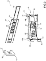
figure 2 is a perspective view of a sled, a guide profile and a mounting tool of a connection system of the door of the built-in refrigerator to the door of the furniture according to a first embodiment of the present invention; -
figures 3 and 4 are two different perspective views of the mounting tool offigure 2 coupled to the guide profile offigure 2 ; -
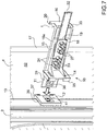
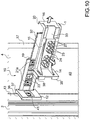
figure 5 is a perspective view of the mounting tool offigure 2 coupled to the guide profile and the sled offigure 2 ; - figures from 6 to 12 show schematic views of the successive connection steps to connect the door of the built-in refrigerator to the door of the furniture, according to the connection method of the invention; and
-
figures 9A and 9B are perspective and enlarged views and on an enlarged scale of successive phases of the step of coupling a screw inside an invitation element of the mounting tool according to a second embodiment of the present invention. - In the figures from 2 to 10, the
number 1 indicates as whole a mounting tool to connect adoor 2 of a built-inrefrigerator 3 to adoor 4 of akitchen furniture 5. - In detail, as shown in
figure 1 , thefurniture 5 has awall 6, a wall 7 which is parallel and opposite to thewall 6, and adoor 4 which is hinged to the wall 7; and the built-inrefrigerator 3 has awall 8, a wall 9 which is parallel and opposite to thewall 8, and adoor 2 which is hinged to the wall 9. In use, the twowalls 6 and 7 of thefurniture 5 are preferably, fixed, respectively, to thewalls 8 and 9 of the built-inrefrigerator 3 by means of known fixing techniques (typically with screw fastening systems), and thedoor 4 of thefurniture 5 is connected to thedoor 2 of the built-inrefrigerator 3 by means of a slidingconnection system 10. - Advantageously, the sliding
connection system 10 is designed to allow to open simultaneous thedoor 2 of the built-inrefrigerator 3 together with thedoor 4 of thefurniture 5, despite thedoor 4 being rotatably mounted (hinged) around a rotation axis X and thedoor 2 is rotatably mounted (hinged) around another rotation axis (not visible in the attached figures) which is arranged offset with respect to the rotation axis X. - The sliding
connection system 10 illustrated in the attached figures (see for examplefigures 1 ,2 ,5 ,7-12 ) comprises aguide profile 11 which is designed to be fixed to thedoor 4 of thefurniture 5 oriented orthogonally to the rotation axis X of thedoor 4, and asled 12 which is designed to be fixed to anouter edge 13 of thedoor 2 of the built-inrefrigerator 3 and to slidably couple to theguide profile 11 so that, when theguide profile 11 is fixed to thedoor 4 of thefurniture 5 and thesled 12 is fixed to theouter edge 13 of thedoor 2 of the built-inrefrigerator 3 and is coupled to theguide profile 11, the sliding of thesled 12 along theguide profile 11 induces the opening of thedoor 2 of the built-inrefrigerator 3 following the opening of thedoor 4 of thefurniture piece 5. - In other words, the sliding of the
sled 12 along the guide profile 11 (and thus the opening, or the closure, of thedoor 2 of the built-in refrigerator 3) is caused by the rotation of thedoor 4 of thefurniture 5 around the rotation axis X (and thus by the opening, or the closing, of thedoor 4 of the furniture 5). - According to the preferred, but not limitative, embodiment shown in the attached figures (see for example
figures 2 and7 ) theguide profile 11 has a "T" shaped cross section and thesled 12 has a "C" shaped cross section to envelop the wings of the "T" section of theguide profile 11. - It is understood that any other configuration of the
sled 12 and/or of theguide profile 11 which allow, in use (i.e. when theguide profile 11 is fixed to thedoor 4 and thesled 12 is fixed to the door 2), a sliding coupling between thesled 12 and theguide profile 11 could be provided. - The
connection system 10 further comprises the mountingtool 1 which can be removably coupled to the guide profile 11 (as shown, for example, infigures 3 and 4 ) and to the sled 12 (as shown, for example, infigure 5 ). - Particularly, according to the embodiment of the invention shown in the attached figures (see, for example,
figures 2 ,3, 4 and 5 ), the mountingtool 1 comprises acoupling plate 14 to allow the removable coupling of the mountingtool 1 with thesled 12 and amain body 15 to allow the removable coupling of the mountingtool 1 with theguide profile 11. - The mounting
tool 1 further comprises areference plate 16 which is designed to abut against anouter edge 17 of thedoor 4 of the furniture 5 (as shown infigures 8 and9 ) so as to define a fixing position of theguide profile 11 to thedoor 4 of thefurniture 5. - In particular, when the mounting
tool 1 is coupled to thesled 12 and to the guide profile 11 (i.e. when thecoupling plate 14 is coupled to thesled 12 and themain body 15 is coupled to the guide profile 11), theguide profile 11 is placed in contact thedoor 4 of thefurniture 5, and thesled 12 is at least opportunely placed (preferably fixed) to theedge 13 of thedoor 2 of the built-in refrigerator 3 (in a condition in which thesled 12 is slidably coupled to the guide profile 11), the mountingtool 1 allows the identification of the fixing position of theguide profile 11, that is to say the identification of that position in which theguide profile 11 is at the correct distance from theedge 17 of thedoor 4 of thefurniture 5 and, at the same time, it is positioned with respect to thesled 12 so as to allow thesled 12 to slide along the guide profile 11 (during the opening and closing of thedoor 4 of the furniture 5) without losing contact with theguide profile 11 itself. - In the preferred but non-limiting embodiment illustrated for example in figures from 2 to 5, the
coupling plate 14 is perpendicular to themain body 15 and is arranged at aninner end 15a of themain body 15, and thereference plate 16 which is perpendicular to themain body 15, is arranged at anouter end 15b of themain body 15 and extends orthogonally to themain body 15 on the opposite side with respect to thecoupling plate 14, thus giving the mounting tool 1 a "Z" shape. - According to non-illustrated variants of the mounting
tool 1, thereference plate 16 is angularly placed with respect to themain body 15 so as to abut against at least part of theouter edge 17 of thedoor 4 of thefurniture piece 5. Similarly, according to a further not shown variant of the invention, (also) thecoupling plate 14 is angularly placed with respect to themain body 15. According to the preferred embodiment of the invention illustrated in the attached figures (see in particularfigures 3, 4, 5 and7 ) themain body 15 is provided with aseat 18 which is designed to house at least a portion of theguide profile 11 in a predetermined position. In detail, according to the preferred but non-limiting embodiment illustrated in the attached figures, theseat 18 has aclosed end 18a against which, in use (i.e. when when the at least a portion of theguide profile 11 is housed in theseat 18 on the predetermined position), anedge 19 of theguide profile 11 abuts (see, for example,figures 3-5 and7-9 ) and anopen end 18b, opposite theclosed end 18a, through which the at least a portion of theguide profile 11 can be slidably inserted into said seat 18 (seefigure 4 ). Therefore, the aforementioned predetermined position of the at least a portion of theguide profile 11 inside the seat 18 (shown for example infigures 3 and 4 ) is the position in which theedge 19 of theguide profile 11 abuts against theclosed end 18a of theseat 18 so as to arrest the sliding of theguide profile 11 with respect to the mountingtool 1. - Further, according to the preferred embodiment shown in figures from 2 to 9, the
reference plate 16 comprises anedge 20 which is arranged perpendicularly to thereference plate 16, protrudes from thereference plate 16 from the same side of themain body 15, and is designed to embrace at least partially theouter edge 17 of thedoor 4 of thefurniture 5, when the at least a portion of theguide profile 11 is housed in theseat 18 in the predetermined position, thecoupling plate 14 is coupled to thesled 12, and thesled 12 is at least properly positioned (preferably already fixed) to theouter edge 13 of thedoor 2 of therefrigerator 3. In this way, by abutting against theedge 17 of thedoor 4 of thefurniture 5, thereference plate 16 defines the fixing position of theguide profile 11, that is the correct position of theguide profile 11 with respect to theedge 17 of thedoor 4 of thefurniture 5 that with respect to thesled 12. - According to the embodiment shown in the attached figures, see for example
figure 9 , theseat 18 is designed to allow, preferably by means of a fixingdevice 21, the fixing of theguide profile 11 to thedoor 4 of thefurniture 5, once the above-described fixing position of theguide profile 11 has been defined. - In accordance with the preferred but non-limiting embodiment of the invention illustrated in figures from 9 to 11, the fixing device 21 (comprises) consists of two
screws 21a, preferably self-threading, intended to be inserted through the mountingtool 1, theguide profile 11, and thedoor 4 of thefurniture 5 thus fixing theguide profile 11 to thedoor 4 itself. According to this preferred but non-limiting embodiment, theguide profile 11 comprises a plurality of throughholes 22, each designed to receive ascrew 21a and the mountingtool 1 comprises a plurality of throughholes 23, each designed to receive arespective screw 21a and each arranged so as to result aligned with a respective throughhole 22, when the mountingtool 1 is coupled to theguide profile 11 in the predetermined position (i.e. when the at least a portion of theguide profile 11 is housed in theseat 18 in the predetermined position) as shown, in particular, infigures 3, 5 ,8 and9 . - In accordance with an not shown embodiment, the fixing device 21 (comprises) consists of only one
screw 21a, theguide profile 11 comprises only one through hole, similar to the throughholes 22 described above and, designed to receive the onescrew 21a and the mountingtool 1 comprises only one through hole which is similar to the throughholes 23 described above and is arranged so as to result aligned with the one through hole of theguide profile 11, when the mountingtool 1 is coupled to theguide profile 11 in the predetermined position. - According to the advantageous but non-limiting embodiment shown in the attached figures (see
figures 2 to 11 ) themain body 15 further comprises a series oftubular invitation elements 24, which protrudes from themain body 15 and are arranged around a respective throughhole 23. Advantageously, the presence of thistubular invitation elements 24 facilitates the correct insertion of thescrew 21a through the mountingtool 1 and theguide profile 11. - With particular reference to
figures 9A and 9B , preferably but not necessarily, eachtubular invitation element 24 comprises a plurality offlaps 25 arranged around the respective throughhole 23 so as to guide astem 26 of thescrew 21a, when thescrew 21a is inserted in the throughhole 23, and a plurality offlaps 27 arranged around the throughhole 23 outside of theflaps 25 so as to guide ahead 28 of thescrew 21a, when thescrew 21a is inserted in the throughhole 23. - Particularly, the
flaps 25 are arranged along acircular profile 29 at an edge (not visible in the attached figures) of the throughhole 23 spaced from one another so that between adjacent flaps 25 a series ofslits 30 are defined. Theflaps 27 are arranged at theseslits 30 so as to allow theflaps 25 to be bent outward of the throughhole 23 when thescrew 21a is inserted in the throughhole 23 and thehead 28 of thescrew 21a contacts thefirst flaps 25 of (as illustrated by the arrows shown infigure 9A-9B ). - The
circular profile 29 along which theflaps 25 are arranged has, indeed, a diameter approximately equal (with clearance) to the external diameter of thestem 26 of thescrew 21a so as to envelop thestem 26 while thescrew 21a is inserted inside the throughhole 23 and to guide thescrew 21a during its advancement. Advantageously, it is ensured that thescrew 21a is correctly inserted in thedoor 4 of thefurniture 5. In this way, the risk of an incorrect placement of theguide profile 11 because of an incorrect insertion of one ormore screws 21a in thedoor 4 of thefurniture 5, which would compromise the correct connection betweendoor 2 of therefrigerator 3 anddoor 4 of thefurniture 5, is minimized. - The
flaps 27 are arranged along a furthercircular profile 31 which is concentric with thecircular profile 29 and has a diameter greater than that of thecircular profile 29. In detail, the diameter of thecircular profile 31 is approximately equal (with clearance) to the outer diameter of thehead 28 of thescrew 21a so as to envelop thehead 28, when thescrew 21a is inserted inside the through hole 23 (thus inside thetubular invitation element 24, if present) so as to guide thescrew 21a during its advancement and to guarantee (together with the first flaps 25) the correct placement of thescrew 21a and therefore of theguide profile 11. - In accordance with a further embodiment illustrated in figures from 2 to 9, the
tubular invitation element 24 comprises only a plurality offlaps 27 arranged around the throughhole 23, preferably spaced from each other, along acircular profile 31 having a diameter approximately equal (with clearance) to the outer diameter of thehead 28 of thescrew 21a so as to guide thehead 28 of thescrew 21a, and thus thescrew 21a, when thescrew 21a is inserted in the throughhole 23 so as to ensure the correct placement of thescrew 21a and then theguide profile 11. - According to the non-limiting embodiment illustrated in figures from 2 to 12, the
guide profile 11 further comprises acover 32 hinged to theguide profile 11 at theedge 19 of thisguide profile 11 and designed to cover the throughholes 22 provided on theguide profile 11 and thescrews 21a inserted in said through holes 22. According to this embodiment, thereference plate 16 comprises a throughopening 33 designed to receive the hingedcover 32 so as to allow passage through the mountingtool 1 of thecover 32, when thecover 32 is in the open configuration (i.e. is angularly arranged with respect to theguide profile 11 so as to leave exposed the throughholes 22 provided on the guide profile 11) and the at least one portion of theguide profile 11 is housed in theseat 18 in the predetermined position. Advantageously, thecover 32 allows to cover thescrews 21a and the throughholes 22, after having fixed theguide profile 11 to thedoor 4 of thefurniture 5 and after having uncoupled the mountingtool 1 from theguide profile 11 and from thesled 12. - According to a further not shown embodiment of the invention, the fixing
device 21 consists of (comprises) an adhesive fixing element which has two parallel and opposite adhesive surfaces, one typically glued from the beginning to theguide profile 11 and the other intended to be glued to thedoor 4 of thefurniture 5, and a removable protective film to initially cover the adhesive surface intended to be fixed to thedoor 4 of thefurniture 5. In this case, when the mountingtool 1 is coupled to the guide profile 11 (i.e. when theseat 18 houses the at least a portion of theguide profile 11 in the above-described predetermined position) and is placed so as to define the fixing position of the guide profile 11 (as explained above), theguide profile 11 can be fixed to thedoor 4 of thefurniture 5 by removing the protective film, for example by means of a graspable removal flap arranged to protrude outwardly from theguide profile 11. - According to a further not shown embodiment of the invention the fixing
device 21 could consist of (or comprise) one or more rivets intended to be inserted in respective through holes opportunely made on theguide profile 11 so as to fix theguide profile 11 to thedoor 4 of thefurniture 5 in the above mentioned fixing position. In this case themain body 15 of the mountingtool 1 could comprise a series of references designed to indicate, when the mountingtool 1 is coupled to theguide profile 11 in the predetermined position, the position at which said one or more through holes must be made. For example, according to a not shown variant of this embodiment, themain body 15 could comprise a series of through openings (optionally each provided with an invitation element similar to thetubular invitations 24 described above) configured to leave exposed the area of theguide profile 11 at which the aforementioned through holes must be made. - With reference to the coupling of the mounting
tool 1 to thesled 12, in the preferred embodiments shown in the attached figures (see for examplefigures 5 and8 ) the mountingtool 1 comprises a snap-on fixingsystem 34 for establishing a connection between thecoupling plate 14 and thesled 12. - In detail, according to the preferred embodiment illustrated in the attached figures, the
coupling plate 14 has anedge 35 which is arranged perpendicularly to thecoupling plate 14 on the side opposite themain body 15, protrudes from thecoupling plate 14 and it is designed to embrace thesled 12 when thecoupling plate 14 is coupled to thesled 12. Preferably but not necessarily, theedge 35 extends on three sides of thecoupling plate 14 leaving free the side facing thedoor 4 of thefurniture 5. - The snap-on fixing
system 34 preferably comprises two recesses 36 (shown in particular infigures 2 ,7 ,10 and11 ) formed on twoedges 37 of thesled 12, preferably parallel to each other, and preferably oriented along the thickness of thedoor 2, when thesled 12 is fixed to thedoor 2, and two teeth 38 (shown in particular infigures 2 ,5 ,6 ,7 ,8 ,9 and10 ) which are provided on / borne by thecoupling plate 14 and are shaped to insert into the tworecesses 36 of thesled 12, when the mountingtool 1 is coupled to thesled 12. - With particular reference to figures from 3 to 12, a method of connecting the
door 2 of the built-inrefrigerator 3 to thedoor 4 of thefurniture 5 is described. This connection method can be implemented using theconnection system 10 described above, and in particular using the mountingtool 1 described above. - In detail, to correctly connect the
door 2 of the built-inrefrigerator 3 to thedoor 4 of thefurniture 5, the installer, after having placed within and appropriately fixed the built-inrefrigerator 3 inside thefurniture 5, couples the mountingtool 1 to theguide profile 11, as shown infigure 3, 5 ,6 . Subsequently, after having fixed (with known methods) thesled 12 to theedge 13 of thedoor 2 of the built-inrefrigerator 3, the installer connects theguide profile 11 to thesled 12, for example, by inserting a protrudingportion 39 of the guide profile 11 (i.e. aportion 39 of theguide profile 11 which protrudes with respect to the mountingtool 1, when the at least one portion of theguide profile 11 is housed in the seat 1) inside the "C" section of thesled 12, so as to make slide theguide profile 11 with respect to thesled 12 until thecoupling plate 14 abuts against thesled 12 so as to realize the aforementioned sliding coupling between theguide profile 11 and thesled 12 and the coupling of the mountingtool 1 to thesled 12. - Subsequently, by opportunely rotating the
door 2 of the built-inrefrigerator 3 and thedoor 4 of thefurniture 5, the installer places the mounting tool 1 (coupled with thesled 12 and with the guide profile 11) on aninner surface 40 of thedoor 4 of thefurniture 5 in a position such that thereference plate 16 abuts against theouter edge 17 of thedoor 4 of thefurniture 5, as shown infigure 8 , so as to define the above-described fixing position and immediately afterwards the installer fixes theguide profile 11 to thedoor 4 of thefurniture 5, preferably by screwing thescrews 21a, as described above and shown infigure 9 . Finally, the installer decouples the mountingtool 1 from theguide profile 11 and from thesled 12, as shown infigure 10 , by pulling the mountingtool 1 and/or by sliding the mountingtool 1 along theguide profile 11 away from thesled 12. - When the
guide profile 11 has acover 32, as described above, the installer preferably, after having removed the mountingtool 1, closes thecover 32 to cover the fixingscrews 21a. - According to a further embodiment of the method of the invention the installer, after having placed within and opportunely fixed the built-in
refrigerator 3 inside thefurniture 5, couples the mountingtool 1 to both theguide profile 11 and thesled 12, then he places the sled 12 (coupled with the mounting tool 1) in contact with theouter edge 13 of thedoor 2 of the built-inrefrigerator 3 and, keeping in position thesled 12, places the mounting tool 1 (coupled with thesled 12 and with the guide profile 11) to theinner surface 40 of thedoor 4 of thefurniture 5 and rotates thedoor 2 of the built-inrefrigerator 3 and thedoor 4 of thefurniture 5 so that thereference plate 16 abuts against theouter edge 17 of thedoor 4 of thefurniture 5 so as to define the fixing position of theguide profile 11, as described above, then he fixes theguide profile 11 to thedoor 4 of thefurniture 5 and thesled 12 to theouter edge 13 of thedoor 2 of the built-inrefrigerator 3. - According to a non-limitative embodiment of the method of the invention, the
sled 12 can be fixed to theedge 13 of thedoor 2 of the built-inrefrigerator 3 by means of a screw 41 (as shown infigures 2 ,7 ,10 ,11 and12 ). In this case, according a non-limitative and not shown embodiment of the invention, thereference plate 16 could be provided with a further through hole, similar to the throughholes 23, and designed to receive thescrew 41 so as to fix thesled 12 to theouter edge 13 of thedoor 2 of the built-inrefrigerator 3, once the fixing position of theguide profile 11 has been defined. - The mounting
tool 1, and the connection method andconnection system 10 described above have numerous advantages. - Firstly, the mounting
tool 1 described above allows the connection of thedoor 2 of the built- inrefrigerator 3 to thedoor 4 of thefurniture 5 in a quickly and easy manner. Indeed, thanks to the use of the mountingtool 1 the identification of the fixing position of theguide profile 11 can be carry out simply coupling the mountingtool 1 to thesled 12 and to theguide profile 11 and then opportunely rotating thedoor 2 and thedoor 4 until thereference plate 16 abuts against at least part of theedge 17 of thedoor 4 of thefurniture 5, without carrying out several measurements as in the prior art. This allows, at the same time, to reduce the risk of error during the installation of theconnection system 10. - Advantageously, the connection method described above can be easily performed even by an unskilled user.
- Moreover, the mounting
tool 1 is easy and inexpensive to manufacture and can be used several times, for different mounting operations. -
- 1
- mounting tool
- 2
- door
- 3
- refrigerator / appliance
- 4
- door
- 5
- furniture
- 6
- wall
- 7
- wall
- 8
- wall
- 9
- wall
- 10
- connection system
- 11
- guide profile
- 12
- sled
- 13
- edge
- 14
- coupling plate
- 15
- main body
- 16
- reference plate
- 17
- edge
- 18
- seat
- 19
- edge
- 20
- edge
- 21
- fixing device
- 22
- through holes
- 23
- through holes
- 24
- tubular invitation element
- 25
- flaps
- 26
- stem
- 27
- flaps
- 28
- head
- 29
- circular profile
- 30
- slit
- 31
- circular profile
- 32
- cover
- 33
- through opening
- 34
- fixing system
- 35
- edge
- 36
- recesses
- 37
- edges
- 38
- teeth
- 39
- protruding portion
- 40
- inner surface
- 41
- screw
- 15a
- inner end
- 15b
- outer end
- 18a
- closed end
- 18b
- open end
- 21a
- screw
- X
- rotation axis
Claims (15)
- A mounting tool (1) for a connection system (10) of a door (2) of a built-in domestic appliance (3) to a door (4) of a furniture (5) that contains the built-in domestic appliance (3); the connection system (10) comprises: a guide profile (11) which is designed to be fixed to the door (4) of the furniture (5) oriented orthogonally to a rotation axis (X) of the door (4); and a sled (12) which is designed to be fixed to an outer edge (13) of the door (2) of the built-in domestic appliance (3) and to slidably couple to the guide profile (11); the mounting tool (1) is configured to removably couple to the sled (12) and to the guide profile (11) and it comprises:a main body (15), which is provided with a seat (18) designed to house at least a portion of the guide profile (11) in a predetermined position and to allow the fixing of the guide profile (11) to the door (4) of the furniture (5) when the at least a portion of the guide profile (11) is housed in the seat (18);a coupling plate (14) which is designed to couple to the sled (12), is angularly placed with respect to the main body (15), and is arranged at a first end (15a) of the main body (15); anda reference plate (16) which is angularly placed with respect to the main body (15), is arranged at a second end (15b) of the main body (15) opposite to the first end (15a), and is designed to abut against an outer edge (17) of the door (4) of the furniture (5), when the coupling plate (14) is coupled to the sled (12), the sled (12) is at least properly positioned on the outer edge (13) of the door (2) of the built-in domestic appliance (3) and the main body (15) is coupled to the guide profile (11), so as to define a fixing position of the guide profile (11) to the door (4) of the furniture (5).
- The mounting tool (1) according to claim 1, wherein the main body (15) is designed to allow, when the at least a portion of the guide profile (11) is housed in the seat (18), the installation of a fixing device (21) suitable to fix the guide profile (11) to the door (4) of the furniture (5).
- The mounting tool (1) according to claim 2, wherein:the fixing device (21) comprises at least a screw (21a) ;the guide profile (11) comprises at least a first through hole (22) designed to receive the screw (21a); andthe main body (15) comprises at least a second through hole (23) arranged so as to be aligned with the first through hole (22) when the at least a portion of the guide profile (11) is housed in the seat (18) on the predetermined position.
- The mounting tool (1) according to claim 3, wherein the main body (15) comprises a tubular invitation element (24) which protrudes from the main body (15) and is arranged around the second through hole (23).
- The mounting tool (1) according to any one of claims from 1 to 4, wherein the reference plate (16) extends orthogonally to the main body (15) on the opposite side with respect to the coupling plate (14), giving to the mounting tool (1) a "Z" shape.
- The mounting tool (1) according to any one of claims from 1 to 5, wherein the coupling plate (14) has an edge (35) which is arranged perpendicularly to the coupling plate (14), protrudes from the coupling plate (14) from the side opposite to the main body (15), and is designed to embrace the sled (12) when the coupling plate (14) is coupled to the sled (12).
- The mounting tool (1) according to any one of claims from 1 to 6, comprising a snap-on fixing system (34) for establishing a connection between the coupling plate (14) and the sled (12).
- The mounting tool (1) according to any one of claims from 1 to 7, wherein the seat (18) of the main body (15) has an open end (18b) through which the at least a portion of the guide profile (11) can be slidably inserted into said seat (18), and has a closed end (18a) against which an edge (19) of the guide profile (11) abuts, on the predetermined position.
- The mounting tool (1) according to any one of claims from 1 to 8, wherein the reference plate (16) comprises an edge (20) which is arranged perpendicularly to the reference plate (16), protrudes from the reference plate (16) from the same side of the main body (15), and is designed to embrace at least partially the door (4) of the furniture (5).
- The mounting tool (1) according to any one of claims from 1 to 9, wherein the reference plate (16) comprises a through opening (33) designed to receive a hinged cover (32) of the guide profile (11), when the at least a portion of the guide profile (11) is housed in the seat (18).
- Connection system (10) of a door (2) of a built-in domestic appliance (3) to a door (4) of a furniture (5) that contains the built-in domestic appliance (3); the connection system (10) comprises:a guide profile (11) which is intended to be fixed to the door (4) of the furniture (5), oriented orthogonally to a rotation axis (X) of the door (4), by means of at least a fixing device (21); anda sled (12) which is intended to be fixed to an outer edge (13) of the door (2) of the built-in domestic appliance (3) and is shaped to slidably couple to the guide profile (11) so that, when the guide profile (11) is fixed to the door (4) of the furniture (5) and the sled (12) is fixed to the outer edge (13) of the door (2) of the built-in domestic appliance (3) and is coupled to the guide profile (11), the sliding of the sled (12) along the guide profile (11) induces the opening of the door (2) of the built-in domestic appliance (3) following the opening of the door (4) of the furniture (5);the connection system (10) is characterized in that it comprises the mounting tool (1) according to any one of the claims from 1 to 10.
- Connection method of a door (2) of a built-in domestic appliance (3) to a door (4) of a furniture (5) using the mounting tool (1) according to any one of the claims from 1 to 10; the connection method comprises the steps of:coupling the mounting tool (1) to the guide profile (11) ;coupling the mounting tool (1) to the sled (12);coupling the guide profile (11) to the sled (12);by appropriately rotating the door (2) of the built-in domestic appliance (3) and the door (4) of the furniture (5), resting the mounting tool (1) coupled with the sled (12) and the guide profile (11) to an internal surface (40) of the door (4) of the furniture (5) in a position such that the reference plate (16) abuts against the outer edge (17) of the door (4) of the furniture (5) and the sled (12) is in contact with the outer edge (13) of the door (2) of the built-in domestic appliance (3);fixing the sled (12) to the outer edge (13) of the door (2) of the built-in domestic appliance (3);fixing the guide profile (11) to the door (4) of the furniture (5) by at the least a fixing device (21); anduncoupling the mounting tool (1) from the guide profile (11) and the sled (12), after fixing the sled (12) to the outer edge (13) of the door (2) of the built-in domestic appliance (3) and the guide profile (11) to the door (4) of the furniture (5).
- Connection method according to claim 12, wherein the sled (12) is fixed to the outer edge (13) of the door (2) of the built-in domestic appliance (3) before coupling the sled (12) to the mounting tool (1).
- Connection method according to claim 12 or 13, wherein the guide profile (11) is coupled to the sled (12) after coupling the mounting tool (1) to the guide profile (11).
- Connection method according to claim 12 or 13 or 14 when depending to claim 10, wherein the step of coupling the mounting tool (1) to the guide profile (11) involves inserting the hinged cover (32) of the guide profile (11) in the through opening (33) formed in the reference plate (16) of the mounting tool (1).
Priority Applications (1)
| Application Number | Priority Date | Filing Date | Title |
|---|---|---|---|
| EP19195603.6A EP3789705B1 (en) | 2019-09-05 | 2019-09-05 | A mounting tool for a connection system of a door of a built-in domestic appliance to a door of a furniture |
Applications Claiming Priority (1)
| Application Number | Priority Date | Filing Date | Title |
|---|---|---|---|
| EP19195603.6A EP3789705B1 (en) | 2019-09-05 | 2019-09-05 | A mounting tool for a connection system of a door of a built-in domestic appliance to a door of a furniture |
Publications (2)
| Publication Number | Publication Date |
|---|---|
| EP3789705A1 true EP3789705A1 (en) | 2021-03-10 |
| EP3789705B1 EP3789705B1 (en) | 2022-08-17 |
Family
ID=67874333
Family Applications (1)
| Application Number | Title | Priority Date | Filing Date |
|---|---|---|---|
| EP19195603.6A Active EP3789705B1 (en) | 2019-09-05 | 2019-09-05 | A mounting tool for a connection system of a door of a built-in domestic appliance to a door of a furniture |
Country Status (1)
| Country | Link |
|---|---|
| EP (1) | EP3789705B1 (en) |
Cited By (6)
| Publication number | Priority date | Publication date | Assignee | Title |
|---|---|---|---|---|
| EP4246069A1 (en) * | 2022-03-18 | 2023-09-20 | Whirlpool Corporation | Slide mechanism for a built-in refrigerator |
| WO2025246959A1 (en) * | 2024-05-31 | 2025-12-04 | 青岛海尔电冰箱有限公司 | Sliding connection device, door body assembly and household appliance device |
| WO2025246961A1 (en) * | 2024-05-31 | 2025-12-04 | 青岛海尔电冰箱有限公司 | Sliding connection device, door assembly and household appliance device |
| WO2026007805A1 (en) * | 2024-07-04 | 2026-01-08 | 青岛海尔电冰箱有限公司 | Sliding connection device, door body assembly and mounting method therefor, and household appliance |
| WO2026007793A1 (en) * | 2024-07-04 | 2026-01-08 | 青岛海尔电冰箱有限公司 | Sliding connection apparatus, door body assembly and mounting method therefor, and household appliance apparatus |
| WO2026007799A1 (en) * | 2024-07-04 | 2026-01-08 | 青岛海尔电冰箱有限公司 | Sliding connection device, door body assembly and mounting method therefor, and household appliance device |
Citations (2)
| Publication number | Priority date | Publication date | Assignee | Title |
|---|---|---|---|---|
| EP0857929A1 (en) * | 1997-02-07 | 1998-08-12 | BSH Bosch und Siemens Hausgeräte GmbH | Refrigerator to be built in a furniture recess |
| EP3032022A1 (en) * | 2014-12-08 | 2016-06-15 | BSH Hausgeräte GmbH | Method for mounting a towing device and assembly kit |
-
2019
- 2019-09-05 EP EP19195603.6A patent/EP3789705B1/en active Active
Patent Citations (2)
| Publication number | Priority date | Publication date | Assignee | Title |
|---|---|---|---|---|
| EP0857929A1 (en) * | 1997-02-07 | 1998-08-12 | BSH Bosch und Siemens Hausgeräte GmbH | Refrigerator to be built in a furniture recess |
| EP3032022A1 (en) * | 2014-12-08 | 2016-06-15 | BSH Hausgeräte GmbH | Method for mounting a towing device and assembly kit |
Cited By (6)
| Publication number | Priority date | Publication date | Assignee | Title |
|---|---|---|---|---|
| EP4246069A1 (en) * | 2022-03-18 | 2023-09-20 | Whirlpool Corporation | Slide mechanism for a built-in refrigerator |
| WO2025246959A1 (en) * | 2024-05-31 | 2025-12-04 | 青岛海尔电冰箱有限公司 | Sliding connection device, door body assembly and household appliance device |
| WO2025246961A1 (en) * | 2024-05-31 | 2025-12-04 | 青岛海尔电冰箱有限公司 | Sliding connection device, door assembly and household appliance device |
| WO2026007805A1 (en) * | 2024-07-04 | 2026-01-08 | 青岛海尔电冰箱有限公司 | Sliding connection device, door body assembly and mounting method therefor, and household appliance |
| WO2026007793A1 (en) * | 2024-07-04 | 2026-01-08 | 青岛海尔电冰箱有限公司 | Sliding connection apparatus, door body assembly and mounting method therefor, and household appliance apparatus |
| WO2026007799A1 (en) * | 2024-07-04 | 2026-01-08 | 青岛海尔电冰箱有限公司 | Sliding connection device, door body assembly and mounting method therefor, and household appliance device |
Also Published As
| Publication number | Publication date |
|---|---|
| EP3789705B1 (en) | 2022-08-17 |
Similar Documents
| Publication | Publication Date | Title |
|---|---|---|
| EP3789705B1 (en) | A mounting tool for a connection system of a door of a built-in domestic appliance to a door of a furniture | |
| US8250713B2 (en) | Hinge assembly adapted to allow cable to be disposed therein quickly | |
| US8382188B2 (en) | Self-adjusting and self-aligning access door | |
| US20160362922A1 (en) | Track Corner Connecting Device For Shower Door, Shower Door Frame And Shower Door | |
| US11889958B2 (en) | Rotating shower rod | |
| CN106839620B (en) | The door attachment device and embedded fridge device of built-in refrigerator | |
| CN220771557U (en) | Door body assembly and refrigerator device | |
| US20060200948A1 (en) | Methods and apparatus for assembling a door handle assembly | |
| US9027988B2 (en) | Striker device for a motor vehicle door lock and a motor vehicle equipped with such striker device | |
| US20150233099A1 (en) | Sink and shower handle restraint | |
| WO2025246959A1 (en) | Sliding connection device, door body assembly and household appliance device | |
| US11038328B2 (en) | Use of flame resistant material with audio/video, information and communication technology equipment enclosure | |
| US20240003478A1 (en) | Stud isolator with integrated nail protection | |
| ATE452320T1 (en) | CABLE CONNECTION | |
| US20120233928A1 (en) | Door structure with easy assembly | |
| US6804891B1 (en) | Door and drawer pull jig | |
| EP1145667A1 (en) | Improved bracket for the door of a built-in refrigerator | |
| EP1882437B1 (en) | Device for fixing a built-in electric household appliance inside the associated compartment of a furniture unit | |
| KR101391249B1 (en) | Roller unit with a fixing element | |
| US2304144A (en) | Catch structure | |
| CN211646604U (en) | Quick connecting structure for embedded water tank | |
| CN102341541B (en) | Junction component of screwless engagement | |
| JP6858329B2 (en) | Side wall panel assembly | |
| RU2471949C2 (en) | Lock, in particular, for sliding doors and similar | |
| CN220928996U (en) | Handle |
Legal Events
| Date | Code | Title | Description |
|---|---|---|---|
| PUAI | Public reference made under article 153(3) epc to a published international application that has entered the european phase |
Free format text: ORIGINAL CODE: 0009012 |
|
| STAA | Information on the status of an ep patent application or granted ep patent |
Free format text: STATUS: THE APPLICATION HAS BEEN PUBLISHED |
|
| AK | Designated contracting states |
Kind code of ref document: A1 Designated state(s): AL AT BE BG CH CY CZ DE DK EE ES FI FR GB GR HR HU IE IS IT LI LT LU LV MC MK MT NL NO PL PT RO RS SE SI SK SM TR |
|
| AX | Request for extension of the european patent |
Extension state: BA ME |
|
| STAA | Information on the status of an ep patent application or granted ep patent |
Free format text: STATUS: REQUEST FOR EXAMINATION WAS MADE |
|
| 17P | Request for examination filed |
Effective date: 20210910 |
|
| RBV | Designated contracting states (corrected) |
Designated state(s): AL AT BE BG CH CY CZ DE DK EE ES FI FR GB GR HR HU IE IS IT LI LT LU LV MC MK MT NL NO PL PT RO RS SE SI SK SM TR |
|
| RIC1 | Information provided on ipc code assigned before grant |
Ipc: E05F 17/00 20060101ALN20220117BHEP Ipc: E05D 11/00 20060101ALN20220117BHEP Ipc: E05B 17/06 20060101ALN20220117BHEP Ipc: F25D 23/02 20060101ALN20220117BHEP Ipc: A47F 3/04 20060101ALI20220117BHEP Ipc: F25D 23/10 20060101AFI20220117BHEP |
|
| GRAP | Despatch of communication of intention to grant a patent |
Free format text: ORIGINAL CODE: EPIDOSNIGR1 |
|
| STAA | Information on the status of an ep patent application or granted ep patent |
Free format text: STATUS: GRANT OF PATENT IS INTENDED |
|
| RIC1 | Information provided on ipc code assigned before grant |
Ipc: E05F 17/00 20060101ALN20220304BHEP Ipc: E05D 11/00 20060101ALN20220304BHEP Ipc: E05B 17/06 20060101ALN20220304BHEP Ipc: F25D 23/02 20060101ALN20220304BHEP Ipc: A47F 3/04 20060101ALI20220304BHEP Ipc: F25D 23/10 20060101AFI20220304BHEP |
|
| INTG | Intention to grant announced |
Effective date: 20220325 |
|
| GRAS | Grant fee paid |
Free format text: ORIGINAL CODE: EPIDOSNIGR3 |
|
| GRAA | (expected) grant |
Free format text: ORIGINAL CODE: 0009210 |
|
| STAA | Information on the status of an ep patent application or granted ep patent |
Free format text: STATUS: THE PATENT HAS BEEN GRANTED |
|
| AK | Designated contracting states |
Kind code of ref document: B1 Designated state(s): AL AT BE BG CH CY CZ DE DK EE ES FI FR GB GR HR HU IE IS IT LI LT LU LV MC MK MT NL NO PL PT RO RS SE SI SK SM TR |
|
| REG | Reference to a national code |
Ref country code: CH Ref legal event code: EP |
|
| REG | Reference to a national code |
Ref country code: DE Ref legal event code: R096 Ref document number: 602019018304 Country of ref document: DE |
|
| REG | Reference to a national code |
Ref country code: IE Ref legal event code: FG4D |
|
| REG | Reference to a national code |
Ref country code: AT Ref legal event code: REF Ref document number: 1512437 Country of ref document: AT Kind code of ref document: T Effective date: 20220915 |
|
| REG | Reference to a national code |
Ref country code: NL Ref legal event code: MP Effective date: 20220817 |
|
| REG | Reference to a national code |
Ref country code: LT Ref legal event code: MG9D |
|
| PG25 | Lapsed in a contracting state [announced via postgrant information from national office to epo] |
Ref country code: SE Free format text: LAPSE BECAUSE OF FAILURE TO SUBMIT A TRANSLATION OF THE DESCRIPTION OR TO PAY THE FEE WITHIN THE PRESCRIBED TIME-LIMIT Effective date: 20220817 Ref country code: RS Free format text: LAPSE BECAUSE OF FAILURE TO SUBMIT A TRANSLATION OF THE DESCRIPTION OR TO PAY THE FEE WITHIN THE PRESCRIBED TIME-LIMIT Effective date: 20220817 Ref country code: PT Free format text: LAPSE BECAUSE OF FAILURE TO SUBMIT A TRANSLATION OF THE DESCRIPTION OR TO PAY THE FEE WITHIN THE PRESCRIBED TIME-LIMIT Effective date: 20221219 Ref country code: NO Free format text: LAPSE BECAUSE OF FAILURE TO SUBMIT A TRANSLATION OF THE DESCRIPTION OR TO PAY THE FEE WITHIN THE PRESCRIBED TIME-LIMIT Effective date: 20221117 Ref country code: NL Free format text: LAPSE BECAUSE OF FAILURE TO SUBMIT A TRANSLATION OF THE DESCRIPTION OR TO PAY THE FEE WITHIN THE PRESCRIBED TIME-LIMIT Effective date: 20220817 Ref country code: LV Free format text: LAPSE BECAUSE OF FAILURE TO SUBMIT A TRANSLATION OF THE DESCRIPTION OR TO PAY THE FEE WITHIN THE PRESCRIBED TIME-LIMIT Effective date: 20220817 Ref country code: LT Free format text: LAPSE BECAUSE OF FAILURE TO SUBMIT A TRANSLATION OF THE DESCRIPTION OR TO PAY THE FEE WITHIN THE PRESCRIBED TIME-LIMIT Effective date: 20220817 Ref country code: FI Free format text: LAPSE BECAUSE OF FAILURE TO SUBMIT A TRANSLATION OF THE DESCRIPTION OR TO PAY THE FEE WITHIN THE PRESCRIBED TIME-LIMIT Effective date: 20220817 |
|
| REG | Reference to a national code |
Ref country code: AT Ref legal event code: MK05 Ref document number: 1512437 Country of ref document: AT Kind code of ref document: T Effective date: 20220817 |
|
| PG25 | Lapsed in a contracting state [announced via postgrant information from national office to epo] |
Ref country code: PL Free format text: LAPSE BECAUSE OF FAILURE TO SUBMIT A TRANSLATION OF THE DESCRIPTION OR TO PAY THE FEE WITHIN THE PRESCRIBED TIME-LIMIT Effective date: 20220817 Ref country code: IS Free format text: LAPSE BECAUSE OF FAILURE TO SUBMIT A TRANSLATION OF THE DESCRIPTION OR TO PAY THE FEE WITHIN THE PRESCRIBED TIME-LIMIT Effective date: 20221217 Ref country code: HR Free format text: LAPSE BECAUSE OF FAILURE TO SUBMIT A TRANSLATION OF THE DESCRIPTION OR TO PAY THE FEE WITHIN THE PRESCRIBED TIME-LIMIT Effective date: 20220817 Ref country code: GR Free format text: LAPSE BECAUSE OF FAILURE TO SUBMIT A TRANSLATION OF THE DESCRIPTION OR TO PAY THE FEE WITHIN THE PRESCRIBED TIME-LIMIT Effective date: 20221118 |
|
| PG25 | Lapsed in a contracting state [announced via postgrant information from national office to epo] |
Ref country code: SM Free format text: LAPSE BECAUSE OF FAILURE TO SUBMIT A TRANSLATION OF THE DESCRIPTION OR TO PAY THE FEE WITHIN THE PRESCRIBED TIME-LIMIT Effective date: 20220817 Ref country code: RO Free format text: LAPSE BECAUSE OF FAILURE TO SUBMIT A TRANSLATION OF THE DESCRIPTION OR TO PAY THE FEE WITHIN THE PRESCRIBED TIME-LIMIT Effective date: 20220817 Ref country code: ES Free format text: LAPSE BECAUSE OF FAILURE TO SUBMIT A TRANSLATION OF THE DESCRIPTION OR TO PAY THE FEE WITHIN THE PRESCRIBED TIME-LIMIT Effective date: 20220817 Ref country code: DK Free format text: LAPSE BECAUSE OF FAILURE TO SUBMIT A TRANSLATION OF THE DESCRIPTION OR TO PAY THE FEE WITHIN THE PRESCRIBED TIME-LIMIT Effective date: 20220817 Ref country code: CZ Free format text: LAPSE BECAUSE OF FAILURE TO SUBMIT A TRANSLATION OF THE DESCRIPTION OR TO PAY THE FEE WITHIN THE PRESCRIBED TIME-LIMIT Effective date: 20220817 Ref country code: AT Free format text: LAPSE BECAUSE OF FAILURE TO SUBMIT A TRANSLATION OF THE DESCRIPTION OR TO PAY THE FEE WITHIN THE PRESCRIBED TIME-LIMIT Effective date: 20220817 |
|
| REG | Reference to a national code |
Ref country code: CH Ref legal event code: PL |
|
| REG | Reference to a national code |
Ref country code: DE Ref legal event code: R097 Ref document number: 602019018304 Country of ref document: DE |
|
| REG | Reference to a national code |
Ref country code: BE Ref legal event code: MM Effective date: 20220930 |
|
| PG25 | Lapsed in a contracting state [announced via postgrant information from national office to epo] |
Ref country code: SK Free format text: LAPSE BECAUSE OF FAILURE TO SUBMIT A TRANSLATION OF THE DESCRIPTION OR TO PAY THE FEE WITHIN THE PRESCRIBED TIME-LIMIT Effective date: 20220817 Ref country code: MC Free format text: LAPSE BECAUSE OF FAILURE TO SUBMIT A TRANSLATION OF THE DESCRIPTION OR TO PAY THE FEE WITHIN THE PRESCRIBED TIME-LIMIT Effective date: 20220817 Ref country code: EE Free format text: LAPSE BECAUSE OF FAILURE TO SUBMIT A TRANSLATION OF THE DESCRIPTION OR TO PAY THE FEE WITHIN THE PRESCRIBED TIME-LIMIT Effective date: 20220817 |
|
| PLBE | No opposition filed within time limit |
Free format text: ORIGINAL CODE: 0009261 |
|
| STAA | Information on the status of an ep patent application or granted ep patent |
Free format text: STATUS: NO OPPOSITION FILED WITHIN TIME LIMIT |
|
| PG25 | Lapsed in a contracting state [announced via postgrant information from national office to epo] |
Ref country code: LU Free format text: LAPSE BECAUSE OF NON-PAYMENT OF DUE FEES Effective date: 20220905 Ref country code: AL Free format text: LAPSE BECAUSE OF FAILURE TO SUBMIT A TRANSLATION OF THE DESCRIPTION OR TO PAY THE FEE WITHIN THE PRESCRIBED TIME-LIMIT Effective date: 20220817 |
|
| 26N | No opposition filed |
Effective date: 20230519 |
|
| PG25 | Lapsed in a contracting state [announced via postgrant information from national office to epo] |
Ref country code: LI Free format text: LAPSE BECAUSE OF NON-PAYMENT OF DUE FEES Effective date: 20220930 Ref country code: IE Free format text: LAPSE BECAUSE OF NON-PAYMENT OF DUE FEES Effective date: 20220905 Ref country code: CH Free format text: LAPSE BECAUSE OF NON-PAYMENT OF DUE FEES Effective date: 20220930 |
|
| P01 | Opt-out of the competence of the unified patent court (upc) registered |
Effective date: 20230625 |
|
| PG25 | Lapsed in a contracting state [announced via postgrant information from national office to epo] |
Ref country code: SI Free format text: LAPSE BECAUSE OF FAILURE TO SUBMIT A TRANSLATION OF THE DESCRIPTION OR TO PAY THE FEE WITHIN THE PRESCRIBED TIME-LIMIT Effective date: 20220817 |
|
| PG25 | Lapsed in a contracting state [announced via postgrant information from national office to epo] |
Ref country code: BE Free format text: LAPSE BECAUSE OF NON-PAYMENT OF DUE FEES Effective date: 20220930 |
|
| PG25 | Lapsed in a contracting state [announced via postgrant information from national office to epo] |
Ref country code: CY Free format text: LAPSE BECAUSE OF FAILURE TO SUBMIT A TRANSLATION OF THE DESCRIPTION OR TO PAY THE FEE WITHIN THE PRESCRIBED TIME-LIMIT Effective date: 20220817 |
|
| PG25 | Lapsed in a contracting state [announced via postgrant information from national office to epo] |
Ref country code: MK Free format text: LAPSE BECAUSE OF FAILURE TO SUBMIT A TRANSLATION OF THE DESCRIPTION OR TO PAY THE FEE WITHIN THE PRESCRIBED TIME-LIMIT Effective date: 20220817 Ref country code: HU Free format text: LAPSE BECAUSE OF FAILURE TO SUBMIT A TRANSLATION OF THE DESCRIPTION OR TO PAY THE FEE WITHIN THE PRESCRIBED TIME-LIMIT; INVALID AB INITIO Effective date: 20190905 |
|
| PG25 | Lapsed in a contracting state [announced via postgrant information from national office to epo] |
Ref country code: TR Free format text: LAPSE BECAUSE OF FAILURE TO SUBMIT A TRANSLATION OF THE DESCRIPTION OR TO PAY THE FEE WITHIN THE PRESCRIBED TIME-LIMIT Effective date: 20220817 |
|
| PG25 | Lapsed in a contracting state [announced via postgrant information from national office to epo] |
Ref country code: BG Free format text: LAPSE BECAUSE OF FAILURE TO SUBMIT A TRANSLATION OF THE DESCRIPTION OR TO PAY THE FEE WITHIN THE PRESCRIBED TIME-LIMIT Effective date: 20220817 |
|
| PG25 | Lapsed in a contracting state [announced via postgrant information from national office to epo] |
Ref country code: MT Free format text: LAPSE BECAUSE OF FAILURE TO SUBMIT A TRANSLATION OF THE DESCRIPTION OR TO PAY THE FEE WITHIN THE PRESCRIBED TIME-LIMIT Effective date: 20220817 |
|
| PGFP | Annual fee paid to national office [announced via postgrant information from national office to epo] |
Ref country code: GB Payment date: 20240924 Year of fee payment: 6 |
|
| PGFP | Annual fee paid to national office [announced via postgrant information from national office to epo] |
Ref country code: FR Payment date: 20240925 Year of fee payment: 6 |
|
| PGFP | Annual fee paid to national office [announced via postgrant information from national office to epo] |
Ref country code: DE Payment date: 20250926 Year of fee payment: 7 |
|
| PGFP | Annual fee paid to national office [announced via postgrant information from national office to epo] |
Ref country code: IT Payment date: 20250922 Year of fee payment: 7 |