EP3789587A1 - Geometry for a turbine engine blade outer air seal - Google Patents
Geometry for a turbine engine blade outer air seal Download PDFInfo
- Publication number
- EP3789587A1 EP3789587A1 EP20192940.3A EP20192940A EP3789587A1 EP 3789587 A1 EP3789587 A1 EP 3789587A1 EP 20192940 A EP20192940 A EP 20192940A EP 3789587 A1 EP3789587 A1 EP 3789587A1
- Authority
- EP
- European Patent Office
- Prior art keywords
- outer air
- blade outer
- platform
- boss structure
- air seal
- Prior art date
- Legal status (The legal status is an assumption and is not a legal conclusion. Google has not performed a legal analysis and makes no representation as to the accuracy of the status listed.)
- Granted
Links
Images

Classifications
-
- F—MECHANICAL ENGINEERING; LIGHTING; HEATING; WEAPONS; BLASTING
- F01—MACHINES OR ENGINES IN GENERAL; ENGINE PLANTS IN GENERAL; STEAM ENGINES
- F01D—NON-POSITIVE DISPLACEMENT MACHINES OR ENGINES, e.g. STEAM TURBINES
- F01D11/00—Preventing or minimising internal leakage of working-fluid, e.g. between stages
- F01D11/08—Preventing or minimising internal leakage of working-fluid, e.g. between stages for sealing space between rotor blade tips and stator
-
- F—MECHANICAL ENGINEERING; LIGHTING; HEATING; WEAPONS; BLASTING
- F01—MACHINES OR ENGINES IN GENERAL; ENGINE PLANTS IN GENERAL; STEAM ENGINES
- F01D—NON-POSITIVE DISPLACEMENT MACHINES OR ENGINES, e.g. STEAM TURBINES
- F01D21/00—Shutting-down of machines or engines, e.g. in emergency; Regulating, controlling, or safety means not otherwise provided for
- F01D21/04—Shutting-down of machines or engines, e.g. in emergency; Regulating, controlling, or safety means not otherwise provided for responsive to undesired position of rotor relative to stator or to breaking-off of a part of the rotor, e.g. indicating such position
- F01D21/045—Shutting-down of machines or engines, e.g. in emergency; Regulating, controlling, or safety means not otherwise provided for responsive to undesired position of rotor relative to stator or to breaking-off of a part of the rotor, e.g. indicating such position special arrangements in stators or in rotors dealing with breaking-off of part of rotor
-
- F—MECHANICAL ENGINEERING; LIGHTING; HEATING; WEAPONS; BLASTING
- F01—MACHINES OR ENGINES IN GENERAL; ENGINE PLANTS IN GENERAL; STEAM ENGINES
- F01D—NON-POSITIVE DISPLACEMENT MACHINES OR ENGINES, e.g. STEAM TURBINES
- F01D11/00—Preventing or minimising internal leakage of working-fluid, e.g. between stages
- F01D11/08—Preventing or minimising internal leakage of working-fluid, e.g. between stages for sealing space between rotor blade tips and stator
- F01D11/12—Preventing or minimising internal leakage of working-fluid, e.g. between stages for sealing space between rotor blade tips and stator using a rubstrip, e.g. erodible. deformable or resiliently-biased part
-
- F—MECHANICAL ENGINEERING; LIGHTING; HEATING; WEAPONS; BLASTING
- F01—MACHINES OR ENGINES IN GENERAL; ENGINE PLANTS IN GENERAL; STEAM ENGINES
- F01D—NON-POSITIVE DISPLACEMENT MACHINES OR ENGINES, e.g. STEAM TURBINES
- F01D25/00—Component parts, details, or accessories, not provided for in, or of interest apart from, other groups
- F01D25/24—Casings; Casing parts, e.g. diaphragms, casing fastenings
- F01D25/246—Fastening of diaphragms or stator-rings
-
- F—MECHANICAL ENGINEERING; LIGHTING; HEATING; WEAPONS; BLASTING
- F01—MACHINES OR ENGINES IN GENERAL; ENGINE PLANTS IN GENERAL; STEAM ENGINES
- F01D—NON-POSITIVE DISPLACEMENT MACHINES OR ENGINES, e.g. STEAM TURBINES
- F01D9/00—Stators
- F01D9/02—Nozzles; Nozzle boxes; Stator blades; Guide conduits, e.g. individual nozzles
- F01D9/04—Nozzles; Nozzle boxes; Stator blades; Guide conduits, e.g. individual nozzles forming ring or sector
-
- F—MECHANICAL ENGINEERING; LIGHTING; HEATING; WEAPONS; BLASTING
- F05—INDEXING SCHEMES RELATING TO ENGINES OR PUMPS IN VARIOUS SUBCLASSES OF CLASSES F01-F04
- F05D—INDEXING SCHEME FOR ASPECTS RELATING TO NON-POSITIVE-DISPLACEMENT MACHINES OR ENGINES, GAS-TURBINES OR JET-PROPULSION PLANTS
- F05D2240/00—Components
- F05D2240/10—Stators
- F05D2240/11—Shroud seal segments
-
- F—MECHANICAL ENGINEERING; LIGHTING; HEATING; WEAPONS; BLASTING
- F05—INDEXING SCHEMES RELATING TO ENGINES OR PUMPS IN VARIOUS SUBCLASSES OF CLASSES F01-F04
- F05D—INDEXING SCHEME FOR ASPECTS RELATING TO NON-POSITIVE-DISPLACEMENT MACHINES OR ENGINES, GAS-TURBINES OR JET-PROPULSION PLANTS
- F05D2240/00—Components
- F05D2240/55—Seals
-
- F—MECHANICAL ENGINEERING; LIGHTING; HEATING; WEAPONS; BLASTING
- F05—INDEXING SCHEMES RELATING TO ENGINES OR PUMPS IN VARIOUS SUBCLASSES OF CLASSES F01-F04
- F05D—INDEXING SCHEME FOR ASPECTS RELATING TO NON-POSITIVE-DISPLACEMENT MACHINES OR ENGINES, GAS-TURBINES OR JET-PROPULSION PLANTS
- F05D2240/00—Components
- F05D2240/80—Platforms for stationary or moving blades
- F05D2240/81—Cooled platforms
-
- F—MECHANICAL ENGINEERING; LIGHTING; HEATING; WEAPONS; BLASTING
- F05—INDEXING SCHEMES RELATING TO ENGINES OR PUMPS IN VARIOUS SUBCLASSES OF CLASSES F01-F04
- F05D—INDEXING SCHEME FOR ASPECTS RELATING TO NON-POSITIVE-DISPLACEMENT MACHINES OR ENGINES, GAS-TURBINES OR JET-PROPULSION PLANTS
- F05D2260/00—Function
- F05D2260/20—Heat transfer, e.g. cooling
-
- Y—GENERAL TAGGING OF NEW TECHNOLOGICAL DEVELOPMENTS; GENERAL TAGGING OF CROSS-SECTIONAL TECHNOLOGIES SPANNING OVER SEVERAL SECTIONS OF THE IPC; TECHNICAL SUBJECTS COVERED BY FORMER USPC CROSS-REFERENCE ART COLLECTIONS [XRACs] AND DIGESTS
- Y02—TECHNOLOGIES OR APPLICATIONS FOR MITIGATION OR ADAPTATION AGAINST CLIMATE CHANGE
- Y02T—CLIMATE CHANGE MITIGATION TECHNOLOGIES RELATED TO TRANSPORTATION
- Y02T50/00—Aeronautics or air transport
- Y02T50/60—Efficient propulsion technologies, e.g. for aircraft
Definitions
- the present disclosure relates generally to blade outer air seal constructions for a gas turbine engine, and more specifically to a blade outer air seal construction including boss feature.
- Gas turbine engines such as those utilized in commercial and military aircraft, include a compressor section that compresses air, a combustor section in which the compressed air is mixed with a fuel and ignited, and a turbine section across which the resultant combustion products are expanded.
- the expansion of the combustion products drives the turbine section to rotate.
- the turbine section is connected to the compressor section via a shaft, the rotation of the turbine section further drives the compressor section to rotate.
- a fan is also connected to the shaft and is driven to rotate via rotation of the turbine as well.
- the primary flowpath connecting the compressor, the combustor, and the turbine section is defined by multiple flowpath components including vanes, rotors, blade outer air seals and the like.
- blade outer air seals are disposed radially outward of the rotors.
- the blade outer air seals are arranged in a circumferential manner.
- a blade outer air seal for a gas turbine engine includes a platform having a leading edge and a trailing edge, and at least one cooling cavity disposed within the platform, a pair of circumferential edges connecting the leading edge and the trailing edge, an end wall protruding radially outward from the platform at the trailing edge, a support hook protruding radially outward from a leading edge of the platform, a boss structure protruding radially outward from the platform and defining a solid kinetic energy path from an inner diameter of the platform to a radially outward facing surface of the boss structure, wherein the boss structure extends less than a circumferential length of the platform.
- the platform includes exactly one boss structure.
- the boss structure is circumferentially centered on the platform.
- a first feather seal intrudes circumferentially into a first circumferential edge of the pair of circumferential edges and a second end seal intruding into a second circumferential edge of the pair of circumferential edges.
- each circumferential edge in the pair of circumferential edges protrudes radially outward form the platform, and wherein the boss structured protrudes radially outwards at least as far as the pair of circumferential edges.
- the boss structure protrudes radially exactly as far as the pair of circumferential edges.
- a gas turbine engine including a compressor section having a plurality of compressor stages, a combustor section fluidly connected to the compressor section, a turbine section fluidly connected to the combustor section and having a plurality of turbine stages, at least one of the turbine sections and the compressor sections including a set of circumferentially arranged rotors and a set of blade outer air seals disposed radially outward of the circumferentially arrange rotors, each of the blade outer air seals being connected to an engine case structure via a case support each blade outer air seal in the set of blade outer air seals including, a platform having a leading edge and a trailing edge, and at least one cooling cavity disposed within the platform, a pair of circumferential edges connecting the leading edge and the trailing edge, an end wall protruding radially outward from the platform at the trailing edge, a support hook protruding radially outward from a leading edge of the platform, a boss structure protruding radi
- each boss structure has a circumferential length at least as long as a circumferential length of the corresponding radially inwardly protruding tab.
- each boss structure is longer than a circumferential length of the corresponding radially inwardly protruding tab.
- each radially inwardly protruding tab and each corresponding boss structure define a sold kinetic energy path during a blade off event.
- each boss structure has a radial height at most as high as the pair of circumferential edges on the corresponding blade outer air seal.
- each boss structure extends a same radial height as the pair of circumferential edges on the corresponding blade outer air seal.
- each of said circumferential edges includes a circumferentially intruding feather seal slot configured to receive a feather seal, and wherein each of the feather seal slots is defined by a lack of radial breakthrough.
- a gap between each boss structure and the corresponding at least one radially inwardly protruding tab aligned is less than 1.905 mm.
- the engine case support comprises a second set of radially inward protruding tabs, and wherein each radially inward protruding tab in the second set is circumferentially aligned with at least one circumferential edge.
- FIG. 1 schematically illustrates a gas turbine engine 20.
- the gas turbine engine 20 is disclosed herein as a two-spool turbofan that generally incorporates a fan section 22, a compressor section 24, a combustor section 26 and a turbine section 28.
- the fan section 22 drives air along a bypass flow path B in a bypass duct defined within a housing 15 such as a fan case or nacelle, and also drives air along a core flow path C for compression and communication into the combustor section 26 then expansion through the turbine section 28.
- the exemplary engine 20 generally includes a low speed spool 30 and a high speed spool 32 mounted for rotation about an engine central longitudinal axis A relative to an engine static structure 36 via several bearing systems 38. It should be understood that various bearing systems 38 at various locations may alternatively or additionally be provided, and the location of bearing systems 38 may be varied as appropriate to the application.
- the low speed spool 30 generally includes an inner shaft 40 that interconnects, a first (or low) pressure compressor 44 and a first (or low) pressure turbine 46.
- the inner shaft 40 is connected to the fan 42 through a speed change mechanism, which in exemplary gas turbine engine 20 is illustrated as a geared architecture 48 to drive a fan 42 at a lower speed than the low speed spool 30.
- the high speed spool 32 includes an outer shaft 50 that interconnects a second (or high) pressure compressor 52 and a second (or high) pressure turbine 54.
- a combustor 56 is arranged in exemplary gas turbine 20 between the high pressure compressor 52 and the high pressure turbine 54.
- a mid-turbine frame 57 of the engine static structure 36 may be arranged generally between the high pressure turbine 54 and the low pressure turbine 46.
- the mid-turbine frame 57 further supports bearing systems 38 in the turbine section 28.
- the inner shaft 40 and the outer shaft 50 are concentric and rotate via bearing systems 38 about the engine central longitudinal axis A which is colline
- the core airflow is compressed by the low pressure compressor 44 then the high pressure compressor 52, mixed and burned with fuel in the combustor 56, then expanded over the high pressure turbine 54 and low pressure turbine 46.
- the mid-turbine frame 57 includes airfoils 59 which are in the core airflow path C.
- the turbines 46, 54 rotationally drive the respective low speed spool 30 and high speed spool 32 in response to the expansion.
- gear system 48 may be located aft of the low pressure compressor, or aft of the combustor section 26 or even aft of turbine section 28, and fan 42 may be positioned forward or aft of the location of gear system 48.
- the engine 20 in one example is a high-bypass geared aircraft engine.
- the engine 20 bypass ratio is greater than about six (6), with an example embodiment being greater than about ten (10)
- the geared architecture 48 is an epicyclic gear train, such as a planetary gear system or other gear system, with a gear reduction ratio of greater than about 2.3
- the low pressure turbine 46 has a pressure ratio that is greater than about five.
- the engine 20 bypass ratio is greater than about ten (10:1)
- the fan diameter is significantly larger than that of the low pressure compressor 44
- the low pressure turbine 46 has a pressure ratio that is greater than about five 5:1.
- Low pressure turbine 46 pressure ratio is pressure measured prior to inlet of low pressure turbine 46 as related to the pressure at the outlet of the low pressure turbine 46 prior to an exhaust nozzle.
- the geared architecture 48 may be an epicycle gear train, such as a planetary gear system or other gear system, with a gear reduction ratio of greater than about 2.3:1 and less than about 5:1. It should be understood, however, that the above parameters are only exemplary of one embodiment of a geared architecture engine and that the present invention is applicable to other gas turbine engines including direct drive turbofans.
- the fan section 22 of the engine 20 is designed for a particular flight condition -- typically cruise at about 0.8 Mach and about 35,000 feet (10,668 meters).
- the flight condition of 0.8 Mach and 35,000 ft (10,668 meters), with the engine at its best fuel consumption - also known as "bucket cruise Thrust Specific Fuel Consumption ('TSFC')" - is the industry standard parameter of lbm of fuel being burned divided by lbf of thrust the engine produces at that minimum point.
- "Low fan pressure ratio” is the pressure ratio across the fan blade alone, without a Fan Exit Guide Vane (“FEGV”) system.
- the low fan pressure ratio as disclosed herein according to one non-limiting embodiment is less than about 1.45.
- Low corrected fan tip speed is the actual fan tip speed in ft/sec divided by an industry standard temperature correction of [(Tram °R) / (518.7 °R)] 0.5 .
- the "Low corrected fan tip speed” as disclosed herein according to one non-limiting embodiment is less than about 1150 ft / second (350.5 meters/second).
- each of which includes rotors and vanes.
- the radially outward portion of the primary flowpath C is comprised of a circumferential ring of blade outer air seals.
- Each of the blade outer air seals includes a circumferential feather seal slot configured to receive a feather seal and seal a gap that can exist between the blade outer air seal and a circumferentially adjacent blade outer air seal.
- one potential hazard that can occur is a rotor blade escaping the rotor disc due to damage, vibrations, or other defects. Such an event is referred to as a blade off event, and can cause the blade to be projected radially outward from the engine shaft.
- Previous blade outer air seal designs included a circumferential rib in close radial proximity to tabs extending radially inward from the support.
- the gap between the ribs and the tabs was small enough to quickly close in the case of a blade off event, thereby providing an almost immediate pathway for kinetic energy from the blade off event to be provided to the engine case.
- FIG. 2 schematically illustrates an exemplary blade outer air seal 100 for use in the engine 20 of Figure 1 .
- the blade outer air seal 100 includes a platform 110 having a leading edge 120 and a trailing edge 122.
- the leading edge 120 is the upstream most edge of the platform 110, relative to an expected flow of fluid through a gas turbine engine including the blade outer air seal, during expected engine operations.
- Near the trailing edge 122 is a radially protruding support wall 140.
- a support hook 130 that protrudes radially outward from the platform 110.
- the support wall 140 and the support hook 130 combine to interface with a static engine support structure and maintain the blade outer air seal 100 in the desired axial and radial position through assembly and operation of the gas turbine engine.
- relative terms such as “radial”, “axial”, “circumferential” and the like are relative to a centerline of an engine incorporating the components.
- circumferential edge walls 150 Extending along the circumferential edges of the platform 110 and connecting the leading edge 120 to the trailing edge 122 are circumferential edge walls 150.
- Structural support ribs 153 connect a downstream end of each circumferential edge wall 150 with a corresponding portion of the support wall 140.
- Protruding circumferentially into each of the circumferential edge walls 150 is a feather seal slot 152.
- the circumferential edge wall 150 protrudes radially outward from the platform along the entire distance from the support hook 130 at the leading edge 120 to the support wall 140 near the trailing edge 122.
- the geometry of the blade outer air seal 100 ensures that the feather seal slot 152 does not break out from (extend through) a radially outward facing surface of the circumferential edge wall 150, thereby improving performance of the feather seal. Extending the circumferential edge walls 150 to prevent radial breakout of the featherseal slot further necessitated a reduction in a radial height of support tabs, as described below.
- cooling cavities 112 are included within the platform 110.
- the cooling cavities 112 allow for the inflow and outflow of a coolant, such as air.
- the cooling cavities 112 introduce a void into the platform 110 and there is not a solid mechanical pathway through the platform 110 at the location of the cooling cavities 112. A rib crossing the cooling cavities 112 would not provide the safety function of the previously utilized ribs due to the void.
- the blade outer air seal 100 includes a boss feature 160 that protrudes radially outward from the platform 110, and extends less than the circumferential length of the platform 110.
- the boss feature 160, as well as the portions of the platform radially inward of the damage center boss 160 are solid material and do not include any voids.
- the boss feature 160 is circumferentially centered on the platform. In alternative examples, the boss feature 160 is circumferentially off-center.
- Figure 3 schematically illustrates a cross section of the blade outer air seal 100 Figure 2 drawn along section line A-A and connected to an engine case via a static support 210.
- the static support 210 includes a radially inward protruding tab 212.
- the radially inward protruding tab 212 extends only a partial circumferential length of the blade outer air seal 100, and corresponds to the boss feature 160 of the blade outer air seal 100.
- the boss feature 160 is circumferentially aligned with the radially inward protruding tab 212.
- the platform 110 is limited to a single boss feature 160.
- additional boss featurees 160 can be included protruding radially outward from the platform 110.
- the additional boss featurees are circumferentially aligned with each other such that each of the boss featurees is positioned at the same axial position.
- each boss feature 160 When placed in an installed position, each boss feature 160 includes a radially outward facing surface that is aligned with the corresponding radially inward protruding tab 212, with the boss feature 160 and the corresponding tab 212 being in the same circumferential position.
- the boss feature 160 extends a radial height 162 that is limited to the height of the circumferential edge wall 150.
- a gap 215. defined between the boss feature 160 and the radially inward protruding tab 212 is a gap 215. In order to ensure almost immediate mechanical closure for the kinetic pathway in the case of a blade off event, the gap 215 is at most 1.905 mm.
- FIG. 4 schematically illustrates a cross section of Figure 3 drawn along line X-X.
- each of the circumferential edge walls 150 corresponds to a radially inward protruding 212, with the radially inward protruding tabs 212 corresponding to the circumferential edge walls 150 being radially outward of two adjacent circumferential edge walls 150.
- a circumferential length 214 of each of the radially inward protruding tabs 212 is slightly less than the circumferential length of the corresponding boss portion 160.
- the slight variance in circumferential length allows the support tabs 212 to compensate for manufacturing variances, while still ensuring that the entirety of the support tab overlaps the corresponding boss 16 and a sufficient mechanical connection to pass kinetic energy is formed.
- the structure disclosed herein allows for the blade outer air seal 100 to have uninterrupted material (i.e. be solid) from the inner diameter surface of the blade outer air seal to the point of contact on the support during a blade out event. This allows for energy that is initiated at the gas path to travel through this material and transfer to the support directly.
- the Support in turn provides a direct mechanical connection to the engine case which aids in blade containment functionality.
Landscapes
- Engineering & Computer Science (AREA)
- Mechanical Engineering (AREA)
- General Engineering & Computer Science (AREA)
- Structures Of Non-Positive Displacement Pumps (AREA)
- Turbine Rotor Nozzle Sealing (AREA)
Abstract
Description
- The present disclosure relates generally to blade outer air seal constructions for a gas turbine engine, and more specifically to a blade outer air seal construction including boss feature.
- Gas turbine engines, such as those utilized in commercial and military aircraft, include a compressor section that compresses air, a combustor section in which the compressed air is mixed with a fuel and ignited, and a turbine section across which the resultant combustion products are expanded. The expansion of the combustion products drives the turbine section to rotate. As the turbine section is connected to the compressor section via a shaft, the rotation of the turbine section further drives the compressor section to rotate. In some examples, a fan is also connected to the shaft and is driven to rotate via rotation of the turbine as well.
- The primary flowpath connecting the compressor, the combustor, and the turbine section is defined by multiple flowpath components including vanes, rotors, blade outer air seals and the like. In order to ensure ideal airflow through the primary flowpath, blade outer air seals are disposed radially outward of the rotors. The blade outer air seals are arranged in a circumferential manner.
- According to an aspect, there is provided a blade outer air seal for a gas turbine engine includes a platform having a leading edge and a trailing edge, and at least one cooling cavity disposed within the platform, a pair of circumferential edges connecting the leading edge and the trailing edge, an end wall protruding radially outward from the platform at the trailing edge, a support hook protruding radially outward from a leading edge of the platform, a boss structure protruding radially outward from the platform and defining a solid kinetic energy path from an inner diameter of the platform to a radially outward facing surface of the boss structure, wherein the boss structure extends less than a circumferential length of the platform.
- In another example of the above described blade outer air seal, the platform includes exactly one boss structure.
- In another example of any of the above described blade outer air seals, the boss structure is circumferentially centered on the platform.
- In another example of any of the above described blade outer air seals, a first feather seal intrudes circumferentially into a first circumferential edge of the pair of circumferential edges and a second end seal intruding into a second circumferential edge of the pair of circumferential edges.
- In another example of any of the above described blade outer air seals, each circumferential edge in the pair of circumferential edges protrudes radially outward form the platform, and wherein the boss structured protrudes radially outwards at least as far as the pair of circumferential edges.
- In another example of any of the above described blade outer air seals, the boss structure protrudes radially exactly as far as the pair of circumferential edges.
- According to an aspect, there is provided a gas turbine engine including a compressor section having a plurality of compressor stages, a combustor section fluidly connected to the compressor section, a turbine section fluidly connected to the combustor section and having a plurality of turbine stages, at least one of the turbine sections and the compressor sections including a set of circumferentially arranged rotors and a set of blade outer air seals disposed radially outward of the circumferentially arrange rotors, each of the blade outer air seals being connected to an engine case structure via a case support each blade outer air seal in the set of blade outer air seals including, a platform having a leading edge and a trailing edge, and at least one cooling cavity disposed within the platform, a pair of circumferential edges connecting the leading edge and the trailing edge, an end wall protruding radially outward from the platform at the trailing edge, a support hook protruding radially outward from a leading edge of the platform, a boss structure protruding radially outward from the platform and defining a solid kinetic energy path from an inner diameter of the platform to a radially outward facing surface of the boss structure, wherein the boss structure extends less than a circumferential length of the platform, and an engine case support connecting each blade outer air seal to an engine case, the case support including a connector received in the support hook of each blade outer air seal, the case support further including at least one radially inwardly protruding tab aligned with the boss structure of each blade outer air seal.
- In another example of the above gas turbine engine, each boss structure has a circumferential length at least as long as a circumferential length of the corresponding radially inwardly protruding tab.
- In another example of any of the above gas turbine engines, the circumferential length of each boss structure is longer than a circumferential length of the corresponding radially inwardly protruding tab.
- In another example of any of the above gas turbine engines, each radially inwardly protruding tab and each corresponding boss structure define a sold kinetic energy path during a blade off event.
- In another example of any of the above gas turbine engines, each boss structure has a radial height at most as high as the pair of circumferential edges on the corresponding blade outer air seal.
- In another example of any of the above gas turbine engines, each boss structure extends a same radial height as the pair of circumferential edges on the corresponding blade outer air seal.
- In another example of any of the above gas turbine engines, each of said circumferential edges includes a circumferentially intruding feather seal slot configured to receive a feather seal, and wherein each of the feather seal slots is defined by a lack of radial breakthrough.
- In another example of any of the above gas turbine engines, a gap between each boss structure and the corresponding at least one radially inwardly protruding tab aligned is less than 1.905 mm.
- In another example of any of the above gas turbine engines, the engine case support comprises a second set of radially inward protruding tabs, and wherein each radially inward protruding tab in the second set is circumferentially aligned with at least one circumferential edge.
- These and other features of the present invention can be best understood from the following specification and drawings, the following of which is a brief description.
-
-
Figure 1 illustrates a high level schematic view of an exemplary gas turbine engine. -
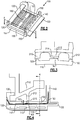
Figure 2 schematically illustrates an isometric view of a blade outer air seal assembly. -
Figure 3 schematically illustrates a cross sectional view of the blade outer air seal assembly ofFigure 2 . -
Figure 4 schematically illustrates a cross sectional view of the blade outer air seal assembly ofFigure 3 . -
Figure 1 schematically illustrates agas turbine engine 20. Thegas turbine engine 20 is disclosed herein as a two-spool turbofan that generally incorporates afan section 22, acompressor section 24, acombustor section 26 and aturbine section 28. Thefan section 22 drives air along a bypass flow path B in a bypass duct defined within ahousing 15 such as a fan case or nacelle, and also drives air along a core flow path C for compression and communication into thecombustor section 26 then expansion through theturbine section 28. Although depicted as a two-spool turbofan gas turbine engine in the disclosed non-limiting embodiment, it should be understood that the concepts described herein are not limited to use with two-spool turbofans as the teachings may be applied to other types of turbine engines including three-spool architectures. - The
exemplary engine 20 generally includes alow speed spool 30 and ahigh speed spool 32 mounted for rotation about an engine central longitudinal axis A relative to an enginestatic structure 36 viaseveral bearing systems 38. It should be understood thatvarious bearing systems 38 at various locations may alternatively or additionally be provided, and the location ofbearing systems 38 may be varied as appropriate to the application. - The
low speed spool 30 generally includes aninner shaft 40 that interconnects, a first (or low) pressure compressor 44 and a first (or low)pressure turbine 46. Theinner shaft 40 is connected to thefan 42 through a speed change mechanism, which in exemplarygas turbine engine 20 is illustrated as a gearedarchitecture 48 to drive afan 42 at a lower speed than thelow speed spool 30. Thehigh speed spool 32 includes anouter shaft 50 that interconnects a second (or high)pressure compressor 52 and a second (or high)pressure turbine 54. Acombustor 56 is arranged inexemplary gas turbine 20 between thehigh pressure compressor 52 and thehigh pressure turbine 54. Amid-turbine frame 57 of the enginestatic structure 36 may be arranged generally between thehigh pressure turbine 54 and thelow pressure turbine 46. Themid-turbine frame 57 further supports bearingsystems 38 in theturbine section 28. Theinner shaft 40 and theouter shaft 50 are concentric and rotate viabearing systems 38 about the engine central longitudinal axis A which is collinear with their longitudinal axes. - The core airflow is compressed by the low pressure compressor 44 then the
high pressure compressor 52, mixed and burned with fuel in thecombustor 56, then expanded over thehigh pressure turbine 54 andlow pressure turbine 46. Themid-turbine frame 57 includesairfoils 59 which are in the core airflow path C. Theturbines low speed spool 30 andhigh speed spool 32 in response to the expansion. It will be appreciated that each of the positions of thefan section 22,compressor section 24,combustor section 26,turbine section 28, and fandrive gear system 48 may be varied. For example,gear system 48 may be located aft of the low pressure compressor, or aft of thecombustor section 26 or even aft ofturbine section 28, andfan 42 may be positioned forward or aft of the location ofgear system 48. - The
engine 20 in one example is a high-bypass geared aircraft engine. In a further example, theengine 20 bypass ratio is greater than about six (6), with an example embodiment being greater than about ten (10), the gearedarchitecture 48 is an epicyclic gear train, such as a planetary gear system or other gear system, with a gear reduction ratio of greater than about 2.3 and thelow pressure turbine 46 has a pressure ratio that is greater than about five. In one disclosed embodiment, theengine 20 bypass ratio is greater than about ten (10:1), the fan diameter is significantly larger than that of the low pressure compressor 44, and thelow pressure turbine 46 has a pressure ratio that is greater than about five 5:1.Low pressure turbine 46 pressure ratio is pressure measured prior to inlet oflow pressure turbine 46 as related to the pressure at the outlet of thelow pressure turbine 46 prior to an exhaust nozzle. The gearedarchitecture 48 may be an epicycle gear train, such as a planetary gear system or other gear system, with a gear reduction ratio of greater than about 2.3:1 and less than about 5:1. It should be understood, however, that the above parameters are only exemplary of one embodiment of a geared architecture engine and that the present invention is applicable to other gas turbine engines including direct drive turbofans. - A significant amount of thrust is provided by the bypass flow B due to the high bypass ratio. The
fan section 22 of theengine 20 is designed for a particular flight condition -- typically cruise at about 0.8 Mach and about 35,000 feet (10,668 meters). The flight condition of 0.8 Mach and 35,000 ft (10,668 meters), with the engine at its best fuel consumption - also known as "bucket cruise Thrust Specific Fuel Consumption ('TSFC')" - is the industry standard parameter of lbm of fuel being burned divided by lbf of thrust the engine produces at that minimum point. "Low fan pressure ratio" is the pressure ratio across the fan blade alone, without a Fan Exit Guide Vane ("FEGV") system. The low fan pressure ratio as disclosed herein according to one non-limiting embodiment is less than about 1.45. "Low corrected fan tip speed" is the actual fan tip speed in ft/sec divided by an industry standard temperature correction of [(Tram °R) / (518.7 °R)]0.5. The "Low corrected fan tip speed" as disclosed herein according to one non-limiting embodiment is less than about 1150 ft / second (350.5 meters/second). - Included within the compressor and turbine sections are multiple stages, each of which includes rotors and vanes. At an axial position of each of the rotors, the radially outward portion of the primary flowpath C is comprised of a circumferential ring of blade outer air seals. Each of the blade outer air seals includes a circumferential feather seal slot configured to receive a feather seal and seal a gap that can exist between the blade outer air seal and a circumferentially adjacent blade outer air seal. During operation of the aircraft engine, one potential hazard that can occur is a rotor blade escaping the rotor disc due to damage, vibrations, or other defects. Such an event is referred to as a blade off event, and can cause the blade to be projected radially outward from the engine shaft.
- Previous blade outer air seal designs included a circumferential rib in close radial proximity to tabs extending radially inward from the support. The gap between the ribs and the tabs was small enough to quickly close in the case of a blade off event, thereby providing an almost immediate pathway for kinetic energy from the blade off event to be provided to the engine case.
- With continued reference to
Figure 1 ,Figure 2 schematically illustrates an exemplary bladeouter air seal 100 for use in theengine 20 ofFigure 1 . The bladeouter air seal 100 includes aplatform 110 having aleading edge 120 and a trailingedge 122. Theleading edge 120 is the upstream most edge of theplatform 110, relative to an expected flow of fluid through a gas turbine engine including the blade outer air seal, during expected engine operations. Near the trailingedge 122 is a radially protrudingsupport wall 140. Similarly, at theleading edge 120 is asupport hook 130 that protrudes radially outward from theplatform 110. Thesupport wall 140 and thesupport hook 130 combine to interface with a static engine support structure and maintain the bladeouter air seal 100 in the desired axial and radial position through assembly and operation of the gas turbine engine. As used herein relative terms such as "radial", "axial", "circumferential" and the like are relative to a centerline of an engine incorporating the components. - Extending along the circumferential edges of the
platform 110 and connecting theleading edge 120 to the trailingedge 122 arecircumferential edge walls 150.Structural support ribs 153 connect a downstream end of eachcircumferential edge wall 150 with a corresponding portion of thesupport wall 140. Protruding circumferentially into each of thecircumferential edge walls 150 is afeather seal slot 152. - The
circumferential edge wall 150 protrudes radially outward from the platform along the entire distance from thesupport hook 130 at theleading edge 120 to thesupport wall 140 near the trailingedge 122. By protruding radially outward from theplatform 110 along the entire distance, the geometry of the bladeouter air seal 100 ensures that thefeather seal slot 152 does not break out from (extend through) a radially outward facing surface of thecircumferential edge wall 150, thereby improving performance of the feather seal. Extending thecircumferential edge walls 150 to prevent radial breakout of the featherseal slot further necessitated a reduction in a radial height of support tabs, as described below. - In order to cool the
platform 110 during engine operations multiple coolingcavities 112 are included within theplatform 110. The coolingcavities 112 allow for the inflow and outflow of a coolant, such as air. The coolingcavities 112 introduce a void into theplatform 110 and there is not a solid mechanical pathway through theplatform 110 at the location of thecooling cavities 112. A rib crossing thecooling cavities 112 would not provide the safety function of the previously utilized ribs due to the void. - To replicate this functionality, without reliance on a pre-existing circumferential rib which provides a solid kinetic energy path, the blade
outer air seal 100 includes aboss feature 160 that protrudes radially outward from theplatform 110, and extends less than the circumferential length of theplatform 110. In order to ensure full damage prevention functionality, theboss feature 160, as well as the portions of the platform radially inward of thedamage center boss 160 are solid material and do not include any voids. In the illustrated example, theboss feature 160 is circumferentially centered on the platform. In alternative examples, theboss feature 160 is circumferentially off-center. - With continued reference to
Figure 2, Figure 3 schematically illustrates a cross section of the bladeouter air seal 100Figure 2 drawn along section line A-A and connected to an engine case via astatic support 210. Thestatic support 210 includes a radially inward protrudingtab 212. The radially inward protrudingtab 212 extends only a partial circumferential length of the bladeouter air seal 100, and corresponds to theboss feature 160 of the bladeouter air seal 100. In order to provide a a sufficient circumferential span of material to block a blade during a blade off event, in the absence of the previously used rib, theboss feature 160 is circumferentially aligned with the radially inward protrudingtab 212. - In the example of
Figures 2 and 3 , theplatform 110 is limited to asingle boss feature 160. In alternative examples,additional boss featurees 160 can be included protruding radially outward from theplatform 110. In some examples, the additional boss featurees are circumferentially aligned with each other such that each of the boss featurees is positioned at the same axial position. - When placed in an installed position, each
boss feature 160 includes a radially outward facing surface that is aligned with the corresponding radially inward protrudingtab 212, with theboss feature 160 and thecorresponding tab 212 being in the same circumferential position. In the example ofFigures 2 and 3 , theboss feature 160 extends aradial height 162 that is limited to the height of thecircumferential edge wall 150. Defined between theboss feature 160 and the radially inward protrudingtab 212 is agap 215. In order to ensure almost immediate mechanical closure for the kinetic pathway in the case of a blade off event, thegap 215 is at most 1.905 mm. - With continued reference to
Figures 2 and 3, Figure 4 schematically illustrates a cross section ofFigure 3 drawn along line X-X. In addition to theboss feature 160 providing a mechanical pathway for kinetic energy, each of thecircumferential edge walls 150 corresponds to a radially inward protruding 212, with the radially inward protrudingtabs 212 corresponding to thecircumferential edge walls 150 being radially outward of two adjacentcircumferential edge walls 150. - In the example of
Figure 4 , acircumferential length 214 of each of the radially inward protrudingtabs 212 is slightly less than the circumferential length of thecorresponding boss portion 160. The slight variance in circumferential length allows thesupport tabs 212 to compensate for manufacturing variances, while still ensuring that the entirety of the support tab overlaps the corresponding boss 16 and a sufficient mechanical connection to pass kinetic energy is formed. - The structure disclosed herein allows for the blade
outer air seal 100 to have uninterrupted material (i.e. be solid) from the inner diameter surface of the blade outer air seal to the point of contact on the support during a blade out event. This allows for energy that is initiated at the gas path to travel through this material and transfer to the support directly. The Support in turn provides a direct mechanical connection to the engine case which aids in blade containment functionality. - It is further understood that any of the above described concepts can be used alone or in combination with any or all of the other above described concepts. Although an embodiment of this invention has been disclosed, a worker of ordinary skill in this art would recognize that certain modifications would come within the scope of this invention. For that reason, the following claims should be studied to determine the true scope and content of this invention.
Claims (15)
- A blade outer air seal for a gas turbine engine comprising:a platform having a leading edge and a trailing edge, and at least one cooling cavity disposed within the platform;a pair of circumferential edges connecting the leading edge and the trailing edge;an end wall protruding radially outward from the platform at the trailing edge;a support hook protruding radially outward from a leading edge of the platform;a boss structure protruding radially outward from the platform and defining a solid kinetic energy path from an inner diameter of the platform to a radially outward facing surface of the boss structure, wherein the boss structure extends less than a circumferential length of the platform.
- The blade outer air seal of claim 1, wherein the platform includes exactly one boss structure.
- The blade outer air seal of claim 1 or 2, wherein the boss structure is circumferentially centered on the platform.
- The blade outer air seal of claim 1, 2 or 3, further comprising a first feather seal intruding circumferentially into a first circumferential edge of the pair of circumferential edges and a second end seal intruding into a second circumferential edge of the pair of circumferential edges.
- The blade outer air seal of any preceding claim, wherein each circumferential edge in the pair of circumferential edges protrudes radially outward from the platform, and wherein the boss structure protrudes radially outwards at least as far as the pair of circumferential edges.
- The blade outer air seal of claim 5, wherein the boss structure protrudes radially exactly as far as the pair of circumferential edges.
- A gas turbine engine comprising:a compressor section having a plurality of compressor stages;a combustor section fluidly connected to the compressor section;a turbine section fluidly connected to the combustor section and having a plurality of turbine stages;at least one of the turbine sections and the compressor sections including a set of circumferentially arranged rotors and a set of blade outer air seals disposed radially outward of the circumferentially arrange rotors, each of the blade outer air seals being connected to an engine case structure via a case support;each blade outer air seal in the set of blade outer air seals being a blade outer air seal according to any preceding claim; andan engine case support connecting each blade outer air seal to an engine case, the case support including a connector received in the support hook of each blade outer air seal, the case support further including at least one radially inwardly protruding tab aligned with the boss structure of each blade outer air seal.
- The gas turbine engine of claim 7, wherein each boss structure has a circumferential length at least as long as a circumferential length of the corresponding radially inwardly protruding tab.
- The gas turbine engine of claim 8, wherein the circumferential length of each boss structure is longer than the circumferential length of the corresponding radially inwardly protruding tab.
- The gas turbine engine of claim 7, 8 or 9, wherein each radially inwardly protruding tab and each corresponding boss structure define a solid kinetic energy path during a blade off event.
- The gas turbine engine of any of claims 7 to 10, wherein each boss structure has a radial height at most as high as the pair of circumferential edges on the corresponding blade outer air seal.
- The gas turbine engine of claim 11, wherein each boss structure extends a same radial height as the pair of circumferential edges on the corresponding blade outer air seal.
- The gas turbine engine of any of claims 7 to 12, wherein each of said circumferential edges includes a circumferentially intruding feather seal slot configured to receive a feather seal, and wherein each of the feather seal slots is defined by a lack of radial breakthrough.
- The gas turbine engine of any of claims 7 to 13, wherein a gap between each boss structure and the corresponding at least one radially inwardly protruding tab aligned is less than 1.905 mm.
- The gas turbine engine of any of claims 7 to 14, wherein the engine case support comprises a second set of radially inward protruding tabs, and wherein each radially inward protruding tab in the second set is circumferentially aligned with at least one circumferential edge.
Applications Claiming Priority (1)
| Application Number | Priority Date | Filing Date | Title |
|---|---|---|---|
| US16/562,527 US11401830B2 (en) | 2019-09-06 | 2019-09-06 | Geometry for a turbine engine blade outer air seal |
Publications (2)
| Publication Number | Publication Date |
|---|---|
| EP3789587A1 true EP3789587A1 (en) | 2021-03-10 |
| EP3789587B1 EP3789587B1 (en) | 2023-07-26 |
Family
ID=72266121
Family Applications (1)
| Application Number | Title | Priority Date | Filing Date |
|---|---|---|---|
| EP20192940.3A Active EP3789587B1 (en) | 2019-09-06 | 2020-08-26 | Gas turbine engine with blade outer air seal |
Country Status (2)
| Country | Link |
|---|---|
| US (1) | US11401830B2 (en) |
| EP (1) | EP3789587B1 (en) |
Families Citing this family (1)
| Publication number | Priority date | Publication date | Assignee | Title |
|---|---|---|---|---|
| US12234735B1 (en) * | 2024-01-31 | 2025-02-25 | Rtx Corporation | CMC BOAS with overlapping seals |
Citations (6)
| Publication number | Priority date | Publication date | Assignee | Title |
|---|---|---|---|---|
| US20130115065A1 (en) * | 2011-11-06 | 2013-05-09 | General Electric Company | Asymmetric radial spline seal for a gas turbine engine |
| US20160123186A1 (en) * | 2014-10-31 | 2016-05-05 | General Electric Company | Shroud assembly for a turbine engine |
| EP3019707A2 (en) * | 2013-07-11 | 2016-05-18 | United Technologies Corporation | Gas turbine rapid response clearance control system with annular piston |
| EP3118419A1 (en) * | 2015-07-15 | 2017-01-18 | Siemens Aktiengesellschaft | Non-concentrically shaped ring segment |
| EP3246523A1 (en) * | 2016-05-19 | 2017-11-22 | United Technologies Corporation | Cooled blade outer air seal |
| EP3543468A1 (en) * | 2018-02-20 | 2019-09-25 | Honeywell International Inc. | Turbine tip shroud assembly with plural shroud segments having inter-segment seal arrangement |
Family Cites Families (6)
| Publication number | Priority date | Publication date | Assignee | Title |
|---|---|---|---|---|
| US20070009349A1 (en) * | 2005-07-11 | 2007-01-11 | General Electric Company | Impingement box for gas turbine shroud |
| US7600967B2 (en) * | 2005-07-30 | 2009-10-13 | United Technologies Corporation | Stator assembly, module and method for forming a rotary machine |
| US8303247B2 (en) * | 2007-09-06 | 2012-11-06 | United Technologies Corporation | Blade outer air seal |
| US8251637B2 (en) * | 2008-05-16 | 2012-08-28 | General Electric Company | Systems and methods for modifying modal vibration associated with a turbine |
| US8876458B2 (en) * | 2011-01-25 | 2014-11-04 | United Technologies Corporation | Blade outer air seal assembly and support |
| US20140127006A1 (en) * | 2012-11-05 | 2014-05-08 | United Technologies Corporation | Blade outer air seal |
-
2019
- 2019-09-06 US US16/562,527 patent/US11401830B2/en active Active
-
2020
- 2020-08-26 EP EP20192940.3A patent/EP3789587B1/en active Active
Patent Citations (6)
| Publication number | Priority date | Publication date | Assignee | Title |
|---|---|---|---|---|
| US20130115065A1 (en) * | 2011-11-06 | 2013-05-09 | General Electric Company | Asymmetric radial spline seal for a gas turbine engine |
| EP3019707A2 (en) * | 2013-07-11 | 2016-05-18 | United Technologies Corporation | Gas turbine rapid response clearance control system with annular piston |
| US20160123186A1 (en) * | 2014-10-31 | 2016-05-05 | General Electric Company | Shroud assembly for a turbine engine |
| EP3118419A1 (en) * | 2015-07-15 | 2017-01-18 | Siemens Aktiengesellschaft | Non-concentrically shaped ring segment |
| EP3246523A1 (en) * | 2016-05-19 | 2017-11-22 | United Technologies Corporation | Cooled blade outer air seal |
| EP3543468A1 (en) * | 2018-02-20 | 2019-09-25 | Honeywell International Inc. | Turbine tip shroud assembly with plural shroud segments having inter-segment seal arrangement |
Also Published As
| Publication number | Publication date |
|---|---|
| US20210071544A1 (en) | 2021-03-11 |
| US11401830B2 (en) | 2022-08-02 |
| EP3789587B1 (en) | 2023-07-26 |
Similar Documents
| Publication | Publication Date | Title |
|---|---|---|
| EP3734018B1 (en) | Seal for a gas turbine engine component and corresponding method | |
| US11661865B2 (en) | Gas turbine engine component | |
| EP3064711B1 (en) | Component for a gas turbine engine, corresponding gas turbine engine and method of forming an airfoil | |
| EP3034794B1 (en) | Wall of a component of a gas turbine engine and corresponding component | |
| EP3296519B1 (en) | Flowpath component for a gas turbine engine including a chordal seal | |
| US10954953B2 (en) | Rotor hub seal | |
| EP3587740A1 (en) | Gas turbine engine component | |
| WO2014189579A2 (en) | Rotatable full ring fairing for a turbine engine | |
| US20180023396A1 (en) | Rotor blade for a gas turbine engine | |
| EP3822459B1 (en) | Blade outer air seal including cooling trench | |
| EP3498978A1 (en) | Gas turbine engine vane with attachment hook | |
| EP3789587B1 (en) | Gas turbine engine with blade outer air seal | |
| US20180080335A1 (en) | Gas turbine engine sealing arrangement | |
| EP3043030B1 (en) | Anti-rotation vane | |
| EP2904217B1 (en) | Static guide vane and corresponding gas turbine engine | |
| EP3450697B1 (en) | Vane cluster and corresponding gas turbine engine | |
| US11274566B2 (en) | Axial retention geometry for a turbine engine blade outer air seal | |
| EP3822460B1 (en) | Gas turbine engine and cooling method | |
| EP3495621B1 (en) | Support ring for a gas turbine engine | |
| EP3647543A1 (en) | Method of designing a gas turbine engine and corresponding gas turbine engine | |
| EP3008290A1 (en) | Turbine vane with variable trailing edge inner radius |
Legal Events
| Date | Code | Title | Description |
|---|---|---|---|
| PUAI | Public reference made under article 153(3) epc to a published international application that has entered the european phase |
Free format text: ORIGINAL CODE: 0009012 |
|
| STAA | Information on the status of an ep patent application or granted ep patent |
Free format text: STATUS: THE APPLICATION HAS BEEN PUBLISHED |
|
| AK | Designated contracting states |
Kind code of ref document: A1 Designated state(s): AL AT BE BG CH CY CZ DE DK EE ES FI FR GB GR HR HU IE IS IT LI LT LU LV MC MK MT NL NO PL PT RO RS SE SI SK SM TR |
|
| AX | Request for extension of the european patent |
Extension state: BA ME |
|
| STAA | Information on the status of an ep patent application or granted ep patent |
Free format text: STATUS: REQUEST FOR EXAMINATION WAS MADE |
|
| 17P | Request for examination filed |
Effective date: 20210910 |
|
| RBV | Designated contracting states (corrected) |
Designated state(s): AL AT BE BG CH CY CZ DE DK EE ES FI FR GB GR HR HU IE IS IT LI LT LU LV MC MK MT NL NO PL PT RO RS SE SI SK SM TR |
|
| STAA | Information on the status of an ep patent application or granted ep patent |
Free format text: STATUS: EXAMINATION IS IN PROGRESS |
|
| 17Q | First examination report despatched |
Effective date: 20220901 |
|
| GRAP | Despatch of communication of intention to grant a patent |
Free format text: ORIGINAL CODE: EPIDOSNIGR1 |
|
| STAA | Information on the status of an ep patent application or granted ep patent |
Free format text: STATUS: GRANT OF PATENT IS INTENDED |
|
| INTG | Intention to grant announced |
Effective date: 20230224 |
|
| GRAS | Grant fee paid |
Free format text: ORIGINAL CODE: EPIDOSNIGR3 |
|
| GRAA | (expected) grant |
Free format text: ORIGINAL CODE: 0009210 |
|
| STAA | Information on the status of an ep patent application or granted ep patent |
Free format text: STATUS: THE PATENT HAS BEEN GRANTED |
|
| AK | Designated contracting states |
Kind code of ref document: B1 Designated state(s): AL AT BE BG CH CY CZ DE DK EE ES FI FR GB GR HR HU IE IS IT LI LT LU LV MC MK MT NL NO PL PT RO RS SE SI SK SM TR |
|
| REG | Reference to a national code |
Ref country code: CH Ref legal event code: EP |
|
| REG | Reference to a national code |
Ref country code: DE Ref legal event code: R096 Ref document number: 602020014341 Country of ref document: DE |
|
| REG | Reference to a national code |
Ref country code: IE Ref legal event code: FG4D |
|
| RAP4 | Party data changed (patent owner data changed or rights of a patent transferred) |
Owner name: RTX CORPORATION |
|
| REG | Reference to a national code |
Ref country code: LT Ref legal event code: MG9D |
|
| REG | Reference to a national code |
Ref country code: NL Ref legal event code: MP Effective date: 20230726 |
|
| REG | Reference to a national code |
Ref country code: AT Ref legal event code: MK05 Ref document number: 1592133 Country of ref document: AT Kind code of ref document: T Effective date: 20230726 |
|
| PG25 | Lapsed in a contracting state [announced via postgrant information from national office to epo] |
Ref country code: NL Free format text: LAPSE BECAUSE OF FAILURE TO SUBMIT A TRANSLATION OF THE DESCRIPTION OR TO PAY THE FEE WITHIN THE PRESCRIBED TIME-LIMIT Effective date: 20230726 |
|
| PG25 | Lapsed in a contracting state [announced via postgrant information from national office to epo] |
Ref country code: GR Free format text: LAPSE BECAUSE OF FAILURE TO SUBMIT A TRANSLATION OF THE DESCRIPTION OR TO PAY THE FEE WITHIN THE PRESCRIBED TIME-LIMIT Effective date: 20231027 |
|
| PG25 | Lapsed in a contracting state [announced via postgrant information from national office to epo] |
Ref country code: IS Free format text: LAPSE BECAUSE OF FAILURE TO SUBMIT A TRANSLATION OF THE DESCRIPTION OR TO PAY THE FEE WITHIN THE PRESCRIBED TIME-LIMIT Effective date: 20231126 |
|
| PG25 | Lapsed in a contracting state [announced via postgrant information from national office to epo] |
Ref country code: SE Free format text: LAPSE BECAUSE OF FAILURE TO SUBMIT A TRANSLATION OF THE DESCRIPTION OR TO PAY THE FEE WITHIN THE PRESCRIBED TIME-LIMIT Effective date: 20230726 Ref country code: RS Free format text: LAPSE BECAUSE OF FAILURE TO SUBMIT A TRANSLATION OF THE DESCRIPTION OR TO PAY THE FEE WITHIN THE PRESCRIBED TIME-LIMIT Effective date: 20230726 Ref country code: PT Free format text: LAPSE BECAUSE OF FAILURE TO SUBMIT A TRANSLATION OF THE DESCRIPTION OR TO PAY THE FEE WITHIN THE PRESCRIBED TIME-LIMIT Effective date: 20231127 Ref country code: NO Free format text: LAPSE BECAUSE OF FAILURE TO SUBMIT A TRANSLATION OF THE DESCRIPTION OR TO PAY THE FEE WITHIN THE PRESCRIBED TIME-LIMIT Effective date: 20231026 Ref country code: LV Free format text: LAPSE BECAUSE OF FAILURE TO SUBMIT A TRANSLATION OF THE DESCRIPTION OR TO PAY THE FEE WITHIN THE PRESCRIBED TIME-LIMIT Effective date: 20230726 Ref country code: LT Free format text: LAPSE BECAUSE OF FAILURE TO SUBMIT A TRANSLATION OF THE DESCRIPTION OR TO PAY THE FEE WITHIN THE PRESCRIBED TIME-LIMIT Effective date: 20230726 Ref country code: IS Free format text: LAPSE BECAUSE OF FAILURE TO SUBMIT A TRANSLATION OF THE DESCRIPTION OR TO PAY THE FEE WITHIN THE PRESCRIBED TIME-LIMIT Effective date: 20231126 Ref country code: HR Free format text: LAPSE BECAUSE OF FAILURE TO SUBMIT A TRANSLATION OF THE DESCRIPTION OR TO PAY THE FEE WITHIN THE PRESCRIBED TIME-LIMIT Effective date: 20230726 Ref country code: GR Free format text: LAPSE BECAUSE OF FAILURE TO SUBMIT A TRANSLATION OF THE DESCRIPTION OR TO PAY THE FEE WITHIN THE PRESCRIBED TIME-LIMIT Effective date: 20231027 Ref country code: FI Free format text: LAPSE BECAUSE OF FAILURE TO SUBMIT A TRANSLATION OF THE DESCRIPTION OR TO PAY THE FEE WITHIN THE PRESCRIBED TIME-LIMIT Effective date: 20230726 Ref country code: AT Free format text: LAPSE BECAUSE OF FAILURE TO SUBMIT A TRANSLATION OF THE DESCRIPTION OR TO PAY THE FEE WITHIN THE PRESCRIBED TIME-LIMIT Effective date: 20230726 |
|
| PG25 | Lapsed in a contracting state [announced via postgrant information from national office to epo] |
Ref country code: PL Free format text: LAPSE BECAUSE OF FAILURE TO SUBMIT A TRANSLATION OF THE DESCRIPTION OR TO PAY THE FEE WITHIN THE PRESCRIBED TIME-LIMIT Effective date: 20230726 |
|
| REG | Reference to a national code |
Ref country code: CH Ref legal event code: PL |
|
| PG25 | Lapsed in a contracting state [announced via postgrant information from national office to epo] |
Ref country code: LU Free format text: LAPSE BECAUSE OF NON-PAYMENT OF DUE FEES Effective date: 20230826 |
|
| PG25 | Lapsed in a contracting state [announced via postgrant information from national office to epo] |
Ref country code: ES Free format text: LAPSE BECAUSE OF FAILURE TO SUBMIT A TRANSLATION OF THE DESCRIPTION OR TO PAY THE FEE WITHIN THE PRESCRIBED TIME-LIMIT Effective date: 20230726 |
|
| REG | Reference to a national code |
Ref country code: DE Ref legal event code: R097 Ref document number: 602020014341 Country of ref document: DE |
|
| PG25 | Lapsed in a contracting state [announced via postgrant information from national office to epo] |
Ref country code: SM Free format text: LAPSE BECAUSE OF FAILURE TO SUBMIT A TRANSLATION OF THE DESCRIPTION OR TO PAY THE FEE WITHIN THE PRESCRIBED TIME-LIMIT Effective date: 20230726 Ref country code: RO Free format text: LAPSE BECAUSE OF FAILURE TO SUBMIT A TRANSLATION OF THE DESCRIPTION OR TO PAY THE FEE WITHIN THE PRESCRIBED TIME-LIMIT Effective date: 20230726 Ref country code: LU Free format text: LAPSE BECAUSE OF NON-PAYMENT OF DUE FEES Effective date: 20230826 Ref country code: ES Free format text: LAPSE BECAUSE OF FAILURE TO SUBMIT A TRANSLATION OF THE DESCRIPTION OR TO PAY THE FEE WITHIN THE PRESCRIBED TIME-LIMIT Effective date: 20230726 Ref country code: EE Free format text: LAPSE BECAUSE OF FAILURE TO SUBMIT A TRANSLATION OF THE DESCRIPTION OR TO PAY THE FEE WITHIN THE PRESCRIBED TIME-LIMIT Effective date: 20230726 Ref country code: DK Free format text: LAPSE BECAUSE OF FAILURE TO SUBMIT A TRANSLATION OF THE DESCRIPTION OR TO PAY THE FEE WITHIN THE PRESCRIBED TIME-LIMIT Effective date: 20230726 Ref country code: CZ Free format text: LAPSE BECAUSE OF FAILURE TO SUBMIT A TRANSLATION OF THE DESCRIPTION OR TO PAY THE FEE WITHIN THE PRESCRIBED TIME-LIMIT Effective date: 20230726 Ref country code: SK Free format text: LAPSE BECAUSE OF FAILURE TO SUBMIT A TRANSLATION OF THE DESCRIPTION OR TO PAY THE FEE WITHIN THE PRESCRIBED TIME-LIMIT Effective date: 20230726 Ref country code: MC Free format text: LAPSE BECAUSE OF FAILURE TO SUBMIT A TRANSLATION OF THE DESCRIPTION OR TO PAY THE FEE WITHIN THE PRESCRIBED TIME-LIMIT Effective date: 20230726 Ref country code: CH Free format text: LAPSE BECAUSE OF NON-PAYMENT OF DUE FEES Effective date: 20230831 |
|
| REG | Reference to a national code |
Ref country code: BE Ref legal event code: MM Effective date: 20230831 |
|
| REG | Reference to a national code |
Ref country code: IE Ref legal event code: MM4A |
|
| PG25 | Lapsed in a contracting state [announced via postgrant information from national office to epo] |
Ref country code: IT Free format text: LAPSE BECAUSE OF FAILURE TO SUBMIT A TRANSLATION OF THE DESCRIPTION OR TO PAY THE FEE WITHIN THE PRESCRIBED TIME-LIMIT Effective date: 20230726 |
|
| PLBE | No opposition filed within time limit |
Free format text: ORIGINAL CODE: 0009261 |
|
| STAA | Information on the status of an ep patent application or granted ep patent |
Free format text: STATUS: NO OPPOSITION FILED WITHIN TIME LIMIT |
|
| 26N | No opposition filed |
Effective date: 20240429 |
|
| PG25 | Lapsed in a contracting state [announced via postgrant information from national office to epo] |
Ref country code: IE Free format text: LAPSE BECAUSE OF NON-PAYMENT OF DUE FEES Effective date: 20230826 |
|
| PG25 | Lapsed in a contracting state [announced via postgrant information from national office to epo] |
Ref country code: IE Free format text: LAPSE BECAUSE OF NON-PAYMENT OF DUE FEES Effective date: 20230826 Ref country code: SI Free format text: LAPSE BECAUSE OF FAILURE TO SUBMIT A TRANSLATION OF THE DESCRIPTION OR TO PAY THE FEE WITHIN THE PRESCRIBED TIME-LIMIT Effective date: 20230726 |
|
| PG25 | Lapsed in a contracting state [announced via postgrant information from national office to epo] |
Ref country code: BE Free format text: LAPSE BECAUSE OF NON-PAYMENT OF DUE FEES Effective date: 20230831 |
|
| PG25 | Lapsed in a contracting state [announced via postgrant information from national office to epo] |
Ref country code: BG Free format text: LAPSE BECAUSE OF FAILURE TO SUBMIT A TRANSLATION OF THE DESCRIPTION OR TO PAY THE FEE WITHIN THE PRESCRIBED TIME-LIMIT Effective date: 20230726 |
|
| PG25 | Lapsed in a contracting state [announced via postgrant information from national office to epo] |
Ref country code: BG Free format text: LAPSE BECAUSE OF FAILURE TO SUBMIT A TRANSLATION OF THE DESCRIPTION OR TO PAY THE FEE WITHIN THE PRESCRIBED TIME-LIMIT Effective date: 20230726 |
|
| PG25 | Lapsed in a contracting state [announced via postgrant information from national office to epo] |
Ref country code: CY Free format text: LAPSE BECAUSE OF FAILURE TO SUBMIT A TRANSLATION OF THE DESCRIPTION OR TO PAY THE FEE WITHIN THE PRESCRIBED TIME-LIMIT; INVALID AB INITIO Effective date: 20200826 |
|
| PG25 | Lapsed in a contracting state [announced via postgrant information from national office to epo] |
Ref country code: HU Free format text: LAPSE BECAUSE OF FAILURE TO SUBMIT A TRANSLATION OF THE DESCRIPTION OR TO PAY THE FEE WITHIN THE PRESCRIBED TIME-LIMIT; INVALID AB INITIO Effective date: 20200826 |
|
| REG | Reference to a national code |
Ref country code: DE Ref legal event code: R081 Ref document number: 602020014341 Country of ref document: DE Owner name: RTX CORPORATION (N.D.GES.D. STAATES DELAWARE),, US Free format text: FORMER OWNER: RAYTHEON TECHNOLOGIES CORPORATION, FARMINGTON, CT, US |
|
| PGFP | Annual fee paid to national office [announced via postgrant information from national office to epo] |
Ref country code: DE Payment date: 20250724 Year of fee payment: 6 |
|
| PGFP | Annual fee paid to national office [announced via postgrant information from national office to epo] |
Ref country code: GB Payment date: 20250724 Year of fee payment: 6 |
|
| PGFP | Annual fee paid to national office [announced via postgrant information from national office to epo] |
Ref country code: FR Payment date: 20250725 Year of fee payment: 6 |
|
| PG25 | Lapsed in a contracting state [announced via postgrant information from national office to epo] |
Ref country code: TR Free format text: LAPSE BECAUSE OF FAILURE TO SUBMIT A TRANSLATION OF THE DESCRIPTION OR TO PAY THE FEE WITHIN THE PRESCRIBED TIME-LIMIT Effective date: 20230726 |
|
| P01 | Opt-out of the competence of the unified patent court (upc) registered |
Free format text: CASE NUMBER: UPC_APP_0019214_3789587/2025 Effective date: 20251223 |