EP3789526A1 - Sewing device - Google Patents
Sewing device Download PDFInfo
- Publication number
- EP3789526A1 EP3789526A1 EP20193257.1A EP20193257A EP3789526A1 EP 3789526 A1 EP3789526 A1 EP 3789526A1 EP 20193257 A EP20193257 A EP 20193257A EP 3789526 A1 EP3789526 A1 EP 3789526A1
- Authority
- EP
- European Patent Office
- Prior art keywords
- portions
- pair
- engagable
- engaging portions
- holding mechanism
- Prior art date
- Legal status (The legal status is an assumption and is not a legal conclusion. Google has not performed a legal analysis and makes no representation as to the accuracy of the status listed.)
- Withdrawn
Links
Images



Classifications
-
- D—TEXTILES; PAPER
- D05—SEWING; EMBROIDERING; TUFTING
- D05B—SEWING
- D05B39/00—Workpiece carriers
- D05B39/005—Quilting frames
-
- D—TEXTILES; PAPER
- D05—SEWING; EMBROIDERING; TUFTING
- D05B—SEWING
- D05B39/00—Workpiece carriers
-
- D—TEXTILES; PAPER
- D05—SEWING; EMBROIDERING; TUFTING
- D05B—SEWING
- D05B11/00—Machines for sewing quilts or mattresses
-
- D—TEXTILES; PAPER
- D05—SEWING; EMBROIDERING; TUFTING
- D05B—SEWING
- D05B21/00—Sewing machines with devices for automatically controlling movement of work-carrier relative to stitch-forming mechanism in order to obtain particular configuration of seam, e.g. program-controlled for sewing collars or for attaching pockets
Definitions
- the present invention relates to a sewing device.
- a sewing device described in Japanese Laid-Open Patent Publication No. 1998-0263240 is able to change the sewing setting region.
- the sewing device includes a presser foot frame, a guide rail, and an outside presser foot, and the like.
- the presser foot frame is a frame-like member having a substantially rectangular shape, and includes an X-direction frame and a Y-direction frame.
- a guide rail extends in the Y direction and is attached to the upper side of the Y-direction frame.
- the guide rail is provided with a plurality of positioning holes lined up in the Y direction.
- the outside presser foot is a frame-like member having a substantially U shape in a plan view, and includes an X-direction arm portion and a pair of Y-direction arm portions.
- the center portion of the X-direction arm portion is fixed to an X-Y feed drive mechanism.
- the pair of Y-direction arm portions are provided on both end portions of the X-direction arm portion and extend in the Y direction.
- the distal end portions of the pair of Y-direction arm portions each include a chuck cylinder.
- the outside presser foot moves to the rear in the Y direction with respect to the presser foot frame by the X-Y feed drive mechanism.
- the outside presser foot is joined to the presser foot frame by the output shafts of the chuck cylinders being inserted into the rear positioning holes in the guide rail. Therefore, the sewing device extends the sewing setting region in the Y direction.
- the sewing device fixes the outside presser foot to the X-Y feed drive mechanism, so the size to which the sewing setting region can be expanded depends on the length of the outside presser foot in the Y direction. Therefore, when the sewing area of an object to be sewn is large, it is necessary to increase the length of the outside presser foot in the Y direction in accordance with the size of the sewing area. At this time, the sewing device requires an installation area corresponding to the increase in the length of the outside presser foot in the Y direction, which may increase the cost.
- the present invention aims to provide a sewing device capable of increasing the sewing region without increasing the installation area.
- a sewing device of present invention includes a shuttle mechanism, a needle bar mechanism, a moving mechanism, and a feed mechanism.
- the shuttle mechanism has a shuttle.
- the needle bar mechanism has a needle bar.
- the needle bar mechanism is provided above the shuttle mechanism.
- the needle bar is adapted to move in an up-down direction.
- the moving mechanism is adapted to move the shuttle mechanism and the needle bar mechanism in a first direction orthogonal to the up-down direction.
- the feed mechanism is adapted to feed a holding mechanism that holds an object to be sewn in a second direction orthogonal to the first direction and the up-down direction.
- the holding mechanism includes a plurality of pairs of engagable portions lining up in the second direction on both end portions in the first direction.
- the feed mechanism includes a pair of engaging portions adapted to move in the second direction and adapted to engage with one of the plurality of pairs of engagable portions.
- the feed mechanism is adapted to move the pair of engaging portions that are engaged with the one of the plurality of pairs of engagable portions, together with the holding mechanism, to one side in the second direction.
- the feed mechanism is adapted to disengage the pair of engaging portions from the one of the plurality of pairs of engagable portions after moving the holding mechanism to the one side in the second direction.
- the feed mechanism is adapted to move the pair of engaging portions to the other side in the second direction that is the side opposite the one side in the second direction after disengaging the pair of engaging portions from the one of the plurality of pairs of engagable portions.
- the feed mechanism is adapted to engage the pair of engaging portions with another of the plurality of pairs of engagable portions after moving the pair of engaging portions to the other side in the second direction.
- the feed mechanism is able to increase the sewing region simply by moving the pair of engaging portions in the second direction, so there is no need to increase the size of the feed mechanism in the second direction. Therefore, the sewing device is able to increase the sewing region without increasing the installation area.
- the sewing device may further include a bed portion, a pair of pillar portions, a beam portion, and a head portion.
- the bed portion may extend parallel to the first direction and the second direction.
- the pair of pillar portions may extend upward from the bed portion, and may be provided apart from each other in the first direction.
- the beam portion may extend in the first direction between the pair of pillar portions.
- the head portion may be provided on the beam portion and may be adapted to movably support the needle bar mechanism in the first direction.
- the feed mechanism may engage the pair of engaging portions with the one of the plurality of pairs of engagable portions below the beam portion and between the pair of pillar portions in the first direction. At this time, the sewing device sets the position where the pair of engaging portions engage with the pair of engagable portions to below the beam portion and to the inside of the pair of pillar portions, so the feed mechanism can be easily controlled.
- the plurality of pairs of engagable portions may respectively protrude upward from the both end portions of the holding mechanism.
- Each of the pair of engaging portions may includes a first clamping portion and a second clamping portion arranged lined up in the first direction.
- the feed mechanism may be adapted to clamps the one of the plurality of pairs of engagable portions from both sides in the first direction with the first clamping portion and the second clamping portion, respectively.
- the sewing device need only control the first clamping portion and the second clamping portion in the first direction, and thus can rapidly engage the pair of engaging portions to the pair of engagable portions.
- the sewing device need only control the first clamping portion and the second clamping portion in the first direction, so the feed mechanism can be easily controlled.
- the feed mechanism may be provided with restricting members.
- the restricting members may be lined up with the pair of engaging portions in the second direction, and the restricting members may be adapted to restrict the movement of the holding mechanism in the second direction. At this time, the sewing device restricts the movement of the holding mechanism in the second direction, so the feed mechanism can be easily controlled.
- the feed mechanism may be provided with a fixed member.
- the fixed member may be adapted to adjust the position of the pair of engaging portions in the up-down direction.
- the sewing device can adjust the position of the pair of engaging portions by aligning them with the position of the pair of engagable portions of the holding mechanism.
- the sewing device 1 of the present invention will be described with reference to FIG. 1 to FIG. 4 .
- the sewing device 1 can sew cloth as an object to be sewn.
- the left-right direction, front-rear direction, and up-down direction shown by the arrows in the drawings will be used.
- the sewing device 1 includes a bed portion 21, a pair of pillar portions 22, a beam portion 23, a head portion 24, mounting tables 9F and 9R, and feed mechanisms 25, etc.
- the bed portion 21 has a base portion 21A and a frame 21B.
- the base portion 21A has a substantially rectangular shape.
- the upper surface of the base portion 21A forms a flat holding surface 21U that extends horizontally.
- a bellows 21R extends in the front-rear direction and are provided near the right end portion of the holding surface 21U.
- a bellows 21L extends in the front-rear direction and is provided near the left end portion of the holding surface 21U.
- Each of the bellows 21R and 21L extends linearly between the front end portion and the rear end portion of the holding surface 21U.
- the bellows 21R and 21L expand and contract in accordance with the forward-rearward reciprocating movement of the pair of feed mechanisms 25 that will be described later.
- the frame 21B is a lattice-like
- the pair of pillar portions 22 includes pillar portions 22R and 22L, each having a substantially square columnar shape.
- the pillar portion 22R on the right side extends upward from the center, in the front-rear direction, of the right end portion of the bed portion 21.
- the pillar portion 22R is positioned to the right of the bellows 21R.
- the pillar portion 22L on the left side extends upward from the center, in the front-rear direction, of the left end portion of the bed portion 21.
- the pillar portion 22L is positioned to the left of the bellows 21L. That is, the pillar portions 22R and 22L are separated in the left-right direction.
- the beam portion 23 extends in the left-right direction between the pillar portions 22R and 22L.
- the beam portion 23 has a housing 23U.
- the housing 23U extends between the upper end portions and the rear end portions of the pillar portions 22R and 22L.
- a rail has a rod-like shape and is provided between the pillar portions 22R and 22L in a space enclosed by the pillar portions 22R and 22L and the housing 23U.
- the rail movably supports the head portion 24 in the left-right direction. That is, the beam portion 23 movably supports the head portion 24 in the left-right direction. As shown in FIG.
- a bellows 23F is provided between each of the front end portions of the pillar portions 22R and 22L and the housing 23U, and both the left and right end portions of the head portion 24.
- the bellows 23F covers, from the front, the rail that supports the head portion 24, and expands and contracts in accordance with the left and right reciprocating movement of the head portion 24 along the rail.
- the head portion 24 is provided on the front side with respect to the beam portion 23.
- the head portion 24 can move in the left-right direction by the driving of an X-moving motor 82 (refer to FIG. 4 ), along a rail inside the beam portion 23 that extends in the left-right direction.
- the head portion 24 is provided with a needle bar mechanism 24A, a presser foot 24B, a thread take-up mechanism 24C, and a tensioner mechanism 24D, etc.
- the needle bar mechanism 24 A includes a needle bar.
- the needle bar extends in the up-down direction and a sewing needle can be attached to the lower end portion of the needle bar.
- the needle bar can move up and down by the driving of a sewing machine motor 81 (refer to FIG. 4 ).
- the shuttle mechanism is provided below the needle bar mechanism 24A and inside the bed portion 21.
- the shuttle mechanism has a shuttle, and can be moved in the left-right direction in synchronization with the head portion 24 by the power of the X-moving motor 82.
- the X-moving motor 82 functions as a moving mechanism capable of moving the shuttle mechanism and the needle bar mechanism 24A in the left-right direction parallel to the horizontal direction.
- the shuttle can be driven by driving the sewing machine motor 81 (refer to FIG. 4 ).
- the presser foot 24B has a through-hole through which the sewing needle passes in accordance with the movement of the needle bar, and presses down from above on the object to be sewn.
- the thread take-up mechanism 24C operates in response to the up and down movement of the needle bar to pull an upper thread up.
- the tensioner mechanism 24D adjusts the tension of the upper thread.
- a holding plate 8 is a plate that extends in the front-rear direction along the holding surface 21U of the bed portion 21, and supports a holding mechanism 85, described later, such that the holding mechanism 85 can slide in the front-rear direction.
- the holding plate 8 includes an opening 8A that extends in the left-right direction.
- the opening 8A passes through the holding plate 8 in the up-down direction. When sewing, the sewing needle moves up and down inside the opening 8A.
- the mounting tables 9F and 9R are front-rear symmetrical structures, and support the holding mechanism 85 such that the holding mechanism 85 can slide in the front-rear direction.
- the mounting table 9F is provided on the front side of the bed portion 21, and the mounting table 9R is provided on the rear side of the bed portion 21.
- Each of the mounting tables 9F and 9R is provided with a frame 41A and a receiving portion 42A.
- the frame 41A is a lattice-like structure that is long in the front-rear direction and supports the receiving portion 42A from below.
- the receiving portion 42A includes a pair of left and right extension portions 96 and a plurality of rollers 29.
- the pair of extension portions 96 pass to the inside of the bellows 21R and 21L and extend in the front-rear direction from the front end of the mounting table 9F to the rear end of the mounting table 9R, respectively.
- a pair of guide rails 95 are provided on the opposing surfaces of the pair of extension portions 96, respectively, and restrict the position of the holding mechanism 85 in the left-right direction, and guide the holding mechanism 85 in the front-rear direction.
- the guide rails 95 have a substantially rectangular shape and extend in the front-rear direction between the front end portions and the rear end portions of the extension portions 96, respectively.
- the plurality of rollers 29 extend in the left-right direction and are arranged lined up in the front-rear direction between the pair of guide rails 95.
- the holding mechanism 85 slides in the front-rear direction on the plurality of rollers 29.
- the holding mechanism 85 is a frame that holds the object to be sewn.
- the holding mechanism 85 can move in the front-rear direction along the guide rails 95. That is, the holding mechanism 85 moves on the holding plate 8 and the plurality of rollers 29.
- Both end portions in the left-right direction of the holding mechanism 85 include five pairs of engagable portions 11.
- the five pairs of engagable portions 11 are arranged a predetermined distance L1 (refer to FIG. 1 ) away from each other in the front-rear direction.
- Each engagable portion 11 has a circular shape in a plan view, and protrudes upward from both end portions of the holding mechanism 85 in the left-right direction.
- the five pairs of engagable portions 11 are formed by engagable portions 111R and 111L, engagable portions 112R and 112L, engagable portions 113R and 113L, engagable portions 114R and 114L, and engagable portions 115R and 115L.
- engagable portions 11 when a single pair of engagable portions 11 is referred to, it may be any of the engagable portions 111R and 111L, the engagable portions 112R and 112L, the engagable portions 113R and 113L, the engagable portions 114R and 114L, or the engagable portions 115R and 115L.
- the engagable portions 111R to 115R on the right side will collectively be referred to as "engagable portions 11R".
- the engagable portions 111L to 115L on the left side will collectively be referred to as "engagable portions 11L”.
- the engagable portions 111R to 115R are provided on the right frame of the holding mechanism 85, and are lined up in order from the front side to the rear side at intervals of the predetermined distance L1.
- the engagable portions 111L to 115L are provided on the left frame of the holding mechanism 85, and are lined up in order from the front side to the rear side at intervals of the predetermined distance L1.
- the holding mechanism 85 includes a handle 85A and a pair of positioning members 18.
- the handle 85A is provided in the center of the holding mechanism 85 in the left-right direction, and on each of both end portions in the front-rear direction.
- the pair of positioning members 18 includes a positioning member 18R on the right side and a positioning member 18L on the left side.
- the positioning members 18R and 18L each have a substantially rectangular parallelepiped shape that extends in the left-right direction.
- the positioning members 18R and 18L can abut against restricting members 16R and 16L that will be described later.
- the positioning member 18R is provided on the right rear end portion of the holding mechanism 85.
- An abutting portion 18A is provided on the left end portion of the positioning member 18R and protrudes upward.
- the positioning member 18L is provided on the left rear end portion of the holding mechanism 85 (refer to FIG. 2 ).
- An abutting portion 18A is also provided on the right end portion of the positioning member 18L and protrudes upward.
- the pair of feed mechanisms 25 will be explained with reference to FIG. 2 and FIG. 3 .
- the pair of feed mechanisms 25 can move the holding mechanism 85 holding the object to be sewn, in the front-rear direction with respect to the needle bar mechanism 24A and the shuttle mechanism, by moving in the front-rear direction.
- One example of the movable range of the pair of feed mechanisms 25 is between an engagement position P1 (refer to FIG. 5 and FIG. 7 ) and a limit position P2 (refer to FIG. 6 and FIG. 8 ) to be described later.
- the pair of feed mechanisms 25 includes feed mechanisms 25R and 25L.
- the feed mechanism 25R is provided on the right side of the bed portion 21, and the feed mechanism 25L is provided on the left side of the bed portion 21.
- the feed mechanisms 25R and 25L are left-right symmetrical structures, so only the feed mechanism 25L will be described in detail, and a detailed description of the feed mechanism 25R will be omitted.
- the operation of the feed mechanism 25R is linked to the operation of the feed mechanism 25L.
- the feed mechanism 25L includes a connecting portion 52, an extension portion 17, a fixed member 13, a support portion 14, an engaging portion 15, and a restricting member 16L.
- the connecting portion 52 is provided between both front and rear end portions of the bellows 21L, and extends upward from the lower end portion.
- the lower end portion of the connecting portion 52 is connected to a belt provided below the bellows 21L.
- the belt is rotated by power from a Y-moving motor 83 (refer to FIG. 4 ) provided inside the bed portion 21 and moves the feed mechanism 25L in the front-rear direction.
- the extension portion 17 is a portion that extends to the right from the upper end portion of the connecting portion 52.
- the extension portion 17 has a substantially rectangular parallelepiped shape that is long in the left-right direction. Four screw holes are provided in the extension portion 17.
- the fixed member 13 is a substantially rectangular plate, and is on the front side of the extension portion 17.
- the fixed member 13 has four through-holes 38 that pass through in the front-rear direction and are long in the up-down direction.
- the fixed member 13 is fastened to the extension portion 17 by four screws 39 through the four through-holes 38.
- the fixed member 13 can move in the up-down direction within the range of the through-holes 38 with the four screws 39 loosened, so the position of the fixed member 13 can be adjusted in the up-down direction.
- the support portion 14 has a substantially rectangular parallelepiped shape that is long in the left-right direction, and the rear surface of the support portion 14 is connected to the fixed member 13.
- the lower surface of the support portion 14 has two recessed portions that are recessed upwards. Each of the two recessed portions extends in the left-right direction.
- the lower surface of the support portion 14 forms a protruding portion 58A having a protruding shape that protrudes downward between the two recessed portions.
- the engaging portion 15 includes a first clamping portion 15A and a second clamping portion 15B.
- the first clamping portion 15A and the second clamping portion 15B have a substantially rectangular parallelepiped shape, and are arranged lined up in the left-right direction on the lower end portion of the support portion 14 (refer to FIG. 2 ).
- the position of the first clamping portion 15A and the second clamping portion 15B in the up-down direction is the same as the position of the engagable portion 11L of the holding mechanism 85 in the up-down direction.
- a recessed portion 58B that is recessed downwards is formed on the upper surface of the first clamping portion 15A and the second clamping portion 15B.
- the recessed portion 58B extends in the left-right direction, and slidably engages with the protruding portion 58A of the support portion 14 in the left-right direction. Therefore, the support portion 14 supports the engaging portion 15 such that the engaging portion 15 can slide in the left-right direction.
- the engaging portion 15 engages with the support portion 14, and the support portion 14 is connected to the fixed member 13, so the position of the engaging portion 15 in the up-down direction can be adjusted by moving the fixed member 13 in the up-down direction.
- the first clamping portion 15A has a groove 31A.
- the groove 31A is recessed to the left at the lower right end portion of the first clamping portion 15A, and has a semicircular shape in a plan view.
- the second clamping portion 15B has a groove 31B.
- the groove 31B is recessed to the right at the lower left end portion of the second clamping portion 15B, and has a semicircular shape in a plan view.
- the first clamping portion 15A and the second clamping portion 15B can be moved to a standby position (refer to FIG. 2 ) and a clamping position (refer to FIG. 3 ) by the driving of a drive mechanism 184A (refer to FIG. 4 ).
- the drive mechanism 184A is an actuator such as an air cylinder, an air chuck, or a solenoid.
- the first clamping portion 15A and the second clamping portion 15B are separated from the engagable portion 11L of the holding mechanism 85 in the left-right direction (refer to FIG. 2 ).
- the first clamping portion 15A and the second clamping portion 15B are close together (refer to FIG. 3 ).
- the groove 31A and the groove 31B form openings that have a substantially circular shape in a plan view.
- the first clamping portion 15A and the second clamping portion 15B clamp the engagable portion 11L at the opening. That is, the engaging portion 15 clamps the engagable portion 11L from both the left and right sides with the first clamping portion 15A and the second clamping portion 15B.
- the engaging portion 15 of each of the feed mechanisms 25L and 25R will collectively be referred to as a pair of engaging portions 15.
- the first clamping portion 15A and the second clamping portion 15B of the pair of engaging portions 15 moving to the clamping position and clamping the pair of engagable portions 11 will also be referred to as "the feed mechanisms 25R and 25L engaging the pair of engaging portions 15 with the pair of engagable portions 11.”
- the first clamping portion 15A and the second clamping portion 15B of the pair of engaging portions 15 moving to the standby position and unclamping the pair of engagable portions 11 will also be referred to as "the feed mechanisms 25R and 25L disengaging the pair of engaging portions 15 from the pair of engagable portions 11.”
- the restricting member 16L has a substantially rectangular parallelepiped shape that extends in the up-down direction, and is provided at the right rear end portion of the extension portion 17. That is, the restricting member 16L is provided lined up in the front-rear direction with the engaging portion 15.
- the restricting member 16L has a protruding portion 16A on a lower end portion of the restricting member 16L.
- the restricting member 16L is an air cylinder, for example.
- the protruding portion 16A of the restricting member 16L is moved in the up-down direction between a retracted position and a protruding position by a drive mechanism 185A (refer to FIG. 4 ).
- the drive mechanism 185A is an air compressor or the like for adjusting the pneumatic pressure inside the air cylinder, for example.
- the protruding portion 16A When the protruding portion 16A is in the retracted position, the protruding portion 16A is retracted upwards and positioned above the positioning member 18L of the holding mechanism 85 in the up-down direction.
- the protruding portion 16A When the protruding portion 16A is in the protruding position, the protruding portion 16A protrudes downwards and is in the same position in the left-right direction and below the upper end of the positioning member 18L in the up-down direction. Therefore, the protruding portion 16A in the protruding position can abut against the abutting portion 18A of the positioning member 18L of the holding mechanism 85.
- the feed mechanism 25R includes the restricting member 16R, and the protruding portion 16A of the restricting member 16R can abut against the abutting portion 18A of the positioning member 18R when in the protruding position.
- the protruding portions 16A of the restricting members 16L and 16R restrict movement of the holding mechanism 85 in the rearward direction.
- the holding mechanism 85 is in a sewing start position where sewing with respect to the object to be sewn can be started (refer to FIG. 5 ).
- the positioning members 18L and 18R are in positions separated from the pair of engaging portions 15 in the up-down direction, and therefore do not interfere with the feed mechanisms 25R and 25L (refer to FIG. 2 and 3 ).
- the engagement position P1 of the feed mechanisms 25R and 25L is a position where the first clamping portion 15A and the second clamping portion 15B are lined up on the left and right of the pair of engagable portions 11, respectively (refer to FIG. 2 ).
- the pair of engaging portions 15 can engage with one of the five pairs of engagable portions 11 at the engagement position P1 (refer to FIG. 3 ).
- the feed mechanisms 25R and 25L can engage the pair of engaging portions 15 with the pair of engagable portions 11, below the beam portion 23 and between the pillar portions 22R and 22L.
- the limit position P2 up to which the feed mechanisms 25R and 25L can move is a position at the rear end of the movable range.
- the distance between the engagement position P1 and the limit position P2 is equivalent to the predetermined distance L1 at which the engagable portions 11 are lined up in the front-rear direction.
- the sewing device 1 has a control portion 10.
- the control portion 10 includes a CPU 30, ROM 32, RAM 33, a storage device 34, an input I/F 87, an output I/F 88, and drive circuits 181 to 185, etc.
- the CPU 30 performs overall control over the operation of the sewing device 1.
- a program and the like to execute sewing processing are stored in the ROM 32 in advance.
- Various types of information generated during the execution of various types of processing are temporarily stored in the RAM 33.
- the storage device 34 is nonvolatile and stores various types of setting values.
- the drive circuits 181 to 185 are connected to the output I/F 88.
- the drive circuit 181 is connected to the sewing machine motor 81, and drives the sewing machine motor 81 in response to a control command from the CPU 30.
- the drive circuit 182 is connected to an X-moving motor 82, and drives the X-moving motor 82 in response to a control command from the CPU 30.
- the drive circuit 183 is connected to a Y-moving motor 83, and drives the Y-moving motor 83 in response to a control command from the CPU 30.
- the drive circuit 184 is connected to a drive mechanism 184A, and drives the first clamping portion 15A and the second clamping portion 15B to the standby position and the clamping position in response to a control command from the CPU 30.
- the drive circuit 185 is connected to a drive mechanism 185A, and drives the protruding portions 16A of the restricting members 16R and 16L to the protruding position and the retracted position in response to a control command from the CPU 30.
- Encoders 191 to 193 and an operating portion 3 and the like are connected to the input I/F 87.
- the encoder 191 is connected to the sewing machine motor 81, and detects the rotation angle phase and the rotation speed of an output shaft of the sewing machine motor 81.
- the CPU 30 acquires the detection results of the encoder 191 from the input I/F 87.
- the detection results of the encoder 191 indicate the position of the needle bar and the sewing needle in the up-down direction.
- the encoder 192 is connected to the X-moving motor 82, and detects the rotational direction, the rotation angle phase, and the rotation speed of an output shaft of the X-moving motor 82.
- the CPU 30 acquires the detection results of the encoder 192 from the input I/F 87.
- the rotation angle phase of the output shaft of the X-moving motor 82 indicates the position of the needle bar mechanism 24A and the shuttle mechanism in the left-right direction.
- the encoder 193 is connected to the Y-moving motor 83, and detects the rotational direction, the rotation angle phase, and the rotation speed of an output shaft of the Y-moving motor 83.
- the CPU 30 acquires the detection results of the encoder 193 from the input I/F 87.
- the rotation angle phase of the output shaft of the Y-moving motor 83 indicates the position of the feed mechanisms 25R and 25L in the front-rear direction.
- the operating portion 3 detects various types of instructions, and the CPU 30 acquires the detection results of the operating portion 3 from the input I/F 87.
- the sewing device 1 arranges the feed mechanisms 25R and 25L at the engagement position P1 (refer to FIG. 5 ).
- the sewing device 1 moves the first clamping portion 15A and the second clamping portion 15B of the feed mechanisms 25R and 25L to the standby position (refer to FIG. 2 ).
- the sewing device 1 moves the protruding portions 16A of the restricting members 16R and 16L to the protruding position (refer to FIG. 2 ).
- An operator operates the handle 85A and the like of the holding mechanism 85 and sends the holding mechanism 85 rearward along the guide rail 95 (refer to FIG. 5 ).
- first clamping portion 15A and the second clamping portion 15B of the pair of engaging portions 15 are arranged to the left and right of the engagable portions 115R and 115L, respectively (refer to FIG. 2 ).
- the operator operates the operating portion 3 to start a sewing operation.
- the feed mechanisms 25R and 25L move the first clamping portion 15A and the second clamping portion 15B from the standby position to the clamping position while the holding mechanism 85 is at the sewing start position (refer to FIG. 2 and FIG. 3 ). Therefore, the feed mechanisms 25R and 25L engage the pair of engaging portions 15 with the engagable portions 115R and 115L of the holding mechanism 85 (refer to FIG. 3 ).
- the protruding portions 16A of the restricting members 16R and 16L are moved from the protruding position to the retracted position by the driving of the drive mechanism 185A.
- the holding mechanism 85 can move in the front-rear direction. The pair of engaging portions 15 remain engaged with the engagable portions 115R and 115L.
- the sewing device 1 starts sewing.
- the sewing device 1 performs sewing by driving the needle bar mechanism 24A and the shuttle with the sewing machine motor 81, while moving the head portion 24 and the shuttle mechanism in the left-right direction by driving the X-moving motor 82.
- the sewing device 1 moves the feed mechanisms 25R and 25L a predetermined distance rearward by driving the Y-moving motor 83. Therefore, the feed mechanisms 25R and 25L move the pair of engaging portions 15 that are engaged with the engagable portions 115R and 115L, together with the holding mechanism 85, a predetermined distance toward the rear.
- the predetermined distance is a predetermined distance in the front-rear direction, and is shorter than the predetermined distance L1.
- the sewing device 1 performs sewing while moving the head portion 24 in the left-right direction after moving the holding mechanism 85 the predetermined distance.
- the sewing device 1 repeats the above operation until the feed mechanisms 25R and 25L reach the rear limit position P2.
- the feed mechanisms 25R and 25L move the first clamping portion 15A and the second clamping portion 15B to the standby position. Therefore, the feed mechanisms 25R and 25L disengage the pair of engaging portions 15 from the engagable portions 115R and 115L.
- the feed mechanisms 25R and 25L move, together with the pair of engaging portions 15, forward to the engagement position P1 (refer to FIG. 7 ).
- the distance from the engagement position P1 to the limit position P2 is equal to the predetermined distance L1 at which the pair of engagable portions 11 are arranged in the front-rear direction.
- the first clamping portion 15A and the second clamping portion 15B are at the same positions, in the front-rear direction, as the engagable portions 114R and 114L that are different from the engagable portions 115R and 115L (refer to FIG. 7 ).
- the feed mechanisms 25R and 25L move the first clamping portion 15A and the second clamping portion 15B from the standby position to the clamping position. Therefore, the feed mechanisms 25R and 25L engage the pair of engaging portions 15 with the engagable portions 114R and 114L, respectively (refer to FIG. 7 ).
- the feed mechanisms 25R and 25L move the pair of engaging portions 15 that are engaged with the engagable portions 114R and 114L, together with the holding mechanism 85, a predetermined distance toward the rear. After moving the feed mechanisms 25R and 25L the predetermined distance, the sewing device 1 sews the object to be sewn while moving the head portion 24 in the left-right direction.
- the feed mechanisms 25R and 25L repeat the above operation until the feed mechanisms 25 reach the rear limit position P2.
- the sewing region further extends rearward by the predetermined distance L1.
- the operation of extending the sewing region by the predetermined distance L1 can be executed four times. That is, if sewing in a sewing region of the predetermined distance L1 in the front-rear direction is counted as one time, the sewing device 1 can execute sewing a total of five times including in the sewing region before the sewing region was extended.
- the feed mechanisms 25R and 25L will be in a state in which the pair of engaging portions 15 are engaged with the engagable portions 111R and 111L.
- the sewing device 1 moves the holding mechanism 85, which has moved to the rear, forward.
- the feed mechanisms 25R and 25L move from the limit position P2 to the engagement position P1 with the pair of engaging portions 15 engaged with the engagable portions 111R and 111L of the holding mechanism 85.
- the feed mechanisms 25R and 25L disengage the pair of engaging portions 15 from the engagable portions 111R and 111L.
- the feed mechanisms 25R and 25L move from the engagement position P1 to the limit position P2.
- the feed mechanisms 25R and 25L engage the pair of engaging portions 15 with the engagable portions 112R and 112L that are at a position corresponding to the rear limit position P2.
- the feed mechanisms 25R and 25L move forward, together with the holding mechanism 85, from the limit position P2 to the engagement position P1. As described above, the sewing device 1 repeatedly moves the holding mechanism 85 forward until the holding mechanism 85 moves to the sewing start position (refer to FIG. 5 ).
- the feed mechanisms 25R and 25L move the pair of engaging portions 15 that are engaged with the engagable portions 115R and 115L, together with the holding mechanism 85, rearward.
- the feed mechanisms 25R and 25L then move the pair of engaging portions 15 that have been disengaged from the engagable portions 115R and 115L forward.
- the feed mechanisms 25R and 25L engages the pair of engaging portions 15 with the other engagable portions 114R and 114L.
- the feed mechanisms 25R and 25L can extend the sewing region simply by moving the pair of engaging portions 15 in the front-rear direction, so it is not necessary to enlarge the size of the feed mechanisms 25R and 25L in the front-rear direction. Therefore, the sewing device 1 can extend the sewing region without increasing the installation area.
- the feed mechanisms 25R and 25L engage the pair of engaging portions 15 with the pair of engagable portions 11 below the beam portion 23 and between the pillar portions 22L and 22R.
- the sewing device 1 sets the position where the pair of engaging portions 15 engage with the pair of engagable portions 11 to below the beam portion 23 and between the pair of pillar portions 22L and 22R, so the feed mechanisms 25R and 25L can easily be controlled.
- the feed mechanisms 25R and 25L clamp the pair of engagable portions 11 with the first clamping portion 15A and the second clamping portion 15B, respectively, from both sides in the left-right direction. Therefore, the sewing device 1 need only control the first clamping portion 15A and the second clamping portion 15B in the left-right direction, which makes it possible to quickly engage the pair of engaging portions 15 with the pair of engagable portions 11. The sewing device 1 need only control the first clamping portion 15A and the second clamping portion 15B in the left-right direction, so the feed mechanisms 25R and 25L can be easily controlled.
- the feed mechanisms 25R and 25L restrict the movement of the holding mechanism 85 in the front-rear direction with the restricting members 16R and 16L. Therefore, the sewing device 1 restricts the movement of the holding mechanism 85 in the front-rear direction, and can thus easily control the feed mechanisms 25R and 25L.
- the fixed members 13 of the feed mechanisms 25 can adjust the position of the pair of engaging portions 15 in the up-down direction. Therefore, the sewing device 1 can adjust the position of the pair of engaging portions 15 by aligning the pair of engaging portions 15 with the position of the pair of engagable portions 11 of the holding mechanism 85.
- the present disclosure is not limited to the embodiment described above.
- the engagement position P1 and the limit position P2 may be set as appropriate.
- the feed mechanisms 25R and 25L may move the holding mechanism 85 forward with the pair of engagable portions 11 engaged with the engaging portions 15.
- the sewing device 1 may sew while optionally moving the feed mechanisms 25R and 25L forward and rearward together with the holding mechanism 85.
- the sewing device 1 may sew while carrying the holding mechanism 85 rearward, and then carrying the holding mechanism 85 forward.
- the drive mechanism 184A is not limited to an air cylinder, an air chuck, or a solenoid, or the like, and may also be an electric cylinder or an electric actuator or the like, as long as it can operate the pair of engaging portions 15.
- the first clamping portion 15A and the second clamping portion 15B may engage with the pair of engagable portions 11 from the front-rear direction or a diagonal direction.
- the feed mechanisms 25R and 25L may include a mechanism to move the first clamping portion 15A and the second clamping portion 15B up and down in order to avoid interference between the first clamping portion 15A and the second clamping portion 15B and the pair of engagable portions 11 when the feed mechanisms 25R and 25L move in the front-rear direction.
- the feed mechanisms 25R and 25L may be able to engage with the pair of engagable portions 11 by clamping the pair of engagable portions 11 with grippers or the like.
- Five pairs of engagable portions 11 of the holding mechanism 85 are provided, but the number of pairs of engagable portions 11 may be four or fewer, or six or more.
- the five pairs of engagable portions 11 need not be arranged at equally spaced intervals in the front-rear direction.
- the feed mechanisms 25R and 25L need only be able to move the pair of engaging portions 15 in correspondence with the intervals at which the pairs of engagable portions 11 are arranged.
- the positioning members 18R and 18L may be located on one of the left or the right.
- the restricting member 16R may be provided on only the feed mechanism 25R, and the restricting member 16R need only abut against the positioning member 18R.
- the positioning members 18R and 18L may be omitted.
- the sewing device 1 may have a structure that moves the holding mechanism 85 to the sewing start position automatically. At this time, the sewing device 1 may identify the sewing start position of the holding mechanism 85 using a position detection sensor or the like.
- the through-hole 38 of the fixed member 13 may be long in the left-right direction. At this time, the feed mechanisms 25R and 25L can be adjusted in the left-right direction. A mechanism that adjusts the height of the connecting portion 52 without adjusting the position of the fixed member 13 may be provided. At this time, the sewing device 1 can carry holding mechanisms 85 of various sizes.
Landscapes
- Engineering & Computer Science (AREA)
- Textile Engineering (AREA)
- Sewing Machines And Sewing (AREA)
Abstract
A sewing device (1) is provided with a feed mechanism (25). A holding mechanism (85) is provided with a plurality of pairs of engagable portions (11) provided lined up in the front-rear direction on both left and right end portions. The feed mechanism includes a pair of engaging portions (15) that can engage with the pair of engagable portions. The feed mechanism engages the pair of engaging portions with the pair of engagable portions, and moves the pair of engaging portions, together with the holding mechanism, to one side in the front-rear direction. The feed mechanism disengages the pair of engaging portions from the pair of engagable portions, and then after disengagement, moves the pair of engaging portions to the other side in the front-rear direction. The feed mechanism engages the pair of engaging portions with another pair of engagable portions.
Description
- The present invention relates to a sewing device.
- A sewing device described in Japanese Laid-Open Patent Publication No.
1998-0263240 - The sewing device fixes the outside presser foot to the X-Y feed drive mechanism, so the size to which the sewing setting region can be expanded depends on the length of the outside presser foot in the Y direction. Therefore, when the sewing area of an object to be sewn is large, it is necessary to increase the length of the outside presser foot in the Y direction in accordance with the size of the sewing area. At this time, the sewing device requires an installation area corresponding to the increase in the length of the outside presser foot in the Y direction, which may increase the cost.
- The present invention aims to provide a sewing device capable of increasing the sewing region without increasing the installation area.
- A sewing device of present invention includes a shuttle mechanism, a needle bar mechanism, a moving mechanism, and a feed mechanism. The shuttle mechanism has a shuttle. The needle bar mechanism has a needle bar. The needle bar mechanism is provided above the shuttle mechanism. The needle bar is adapted to move in an up-down direction. The moving mechanism is adapted to move the shuttle mechanism and the needle bar mechanism in a first direction orthogonal to the up-down direction. The feed mechanism is adapted to feed a holding mechanism that holds an object to be sewn in a second direction orthogonal to the first direction and the up-down direction. The holding mechanism includes a plurality of pairs of engagable portions lining up in the second direction on both end portions in the first direction. The feed mechanism includes a pair of engaging portions adapted to move in the second direction and adapted to engage with one of the plurality of pairs of engagable portions. The feed mechanism is adapted to move the pair of engaging portions that are engaged with the one of the plurality of pairs of engagable portions, together with the holding mechanism, to one side in the second direction. The feed mechanism is adapted to disengage the pair of engaging portions from the one of the plurality of pairs of engagable portions after moving the holding mechanism to the one side in the second direction. The feed mechanism is adapted to move the pair of engaging portions to the other side in the second direction that is the side opposite the one side in the second direction after disengaging the pair of engaging portions from the one of the plurality of pairs of engagable portions. The feed mechanism is adapted to engage the pair of engaging portions with another of the plurality of pairs of engagable portions after moving the pair of engaging portions to the other side in the second direction. With the sewing device, the feed mechanism is able to increase the sewing region simply by moving the pair of engaging portions in the second direction, so there is no need to increase the size of the feed mechanism in the second direction. Therefore, the sewing device is able to increase the sewing region without increasing the installation area.
- The sewing device may further include a bed portion, a pair of pillar portions, a beam portion, and a head portion. The bed portion may extend parallel to the first direction and the second direction. The pair of pillar portions may extend upward from the bed portion, and may be provided apart from each other in the first direction. The beam portion may extend in the first direction between the pair of pillar portions. The head portion may be provided on the beam portion and may be adapted to movably support the needle bar mechanism in the first direction. The feed mechanism may engage the pair of engaging portions with the one of the plurality of pairs of engagable portions below the beam portion and between the pair of pillar portions in the first direction. At this time, the sewing device sets the position where the pair of engaging portions engage with the pair of engagable portions to below the beam portion and to the inside of the pair of pillar portions, so the feed mechanism can be easily controlled.
- In the sewing device, the plurality of pairs of engagable portions may respectively protrude upward from the both end portions of the holding mechanism. Each of the pair of engaging portions may includes a first clamping portion and a second clamping portion arranged lined up in the first direction. The feed mechanism may be adapted to clamps the one of the plurality of pairs of engagable portions from both sides in the first direction with the first clamping portion and the second clamping portion, respectively. At this time, the sewing device need only control the first clamping portion and the second clamping portion in the first direction, and thus can rapidly engage the pair of engaging portions to the pair of engagable portions. The sewing device need only control the first clamping portion and the second clamping portion in the first direction, so the feed mechanism can be easily controlled.
- In the sewing device, the feed mechanism may be provided with restricting members. The restricting members may be lined up with the pair of engaging portions in the second direction, and the restricting members may be adapted to restrict the movement of the holding mechanism in the second direction. At this time, the sewing device restricts the movement of the holding mechanism in the second direction, so the feed mechanism can be easily controlled.
- In the sewing device, the feed mechanism may be provided with a fixed member. The fixed member may be adapted to adjust the position of the pair of engaging portions in the up-down direction. At this time, the sewing device can adjust the position of the pair of engaging portions by aligning them with the position of the pair of engagable portions of the holding mechanism.
- Embodiments will be described below in detail with reference to the accompanying drawings in which:
-
FIG. 1 is a perspective view of asewing device 1; -
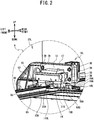
FIG. 2 is an expanded perspective view of afeed mechanism 25L when afirst clamping portion 15A and asecond clamping portion 15B in region A inFIG. 1 are at a standby position; -
FIG. 3 is an enlarged perspective view of thefeed mechanism 25L when thefirst clamping portion 15A and thesecond clamping portion 15B in region A inFIG. 1 are at a clamping position; -
FIG. 4 is a block diagram illustrating an electrical configuration of thesewing device 1; -
FIG. 5 is a plan view of thesewing device 1 when aholding mechanism 85 is in a sewing start position; -
FIG. 6 is a plan view of thesewing device 1 when thefeed mechanisms holding mechanism 85, to a limit position P2 from the positions where thefeed mechanisms FIG. 5 ; -
FIG. 7 is a plan view of thesewing device 1 when only thefeed mechanism feed mechanisms FIG. 6 ; and -
FIG. 8 is a plan view of thesewing device 1 when thefeed mechanisms holding mechanism 85, to the limit position P2 from the positions where thefeed mechanisms FIG. 7 . - The
sewing device 1 of the present invention will be described with reference toFIG. 1 to FIG. 4 . Thesewing device 1 can sew cloth as an object to be sewn. In the description below, the left-right direction, front-rear direction, and up-down direction shown by the arrows in the drawings will be used. - The
sewing device 1 includes abed portion 21, a pair ofpillar portions 22, abeam portion 23, ahead portion 24, mounting tables 9F and 9R, and feedmechanisms 25, etc. Thebed portion 21 has abase portion 21A and aframe 21B. Thebase portion 21A has a substantially rectangular shape. The upper surface of thebase portion 21A forms aflat holding surface 21U that extends horizontally. A bellows 21R extends in the front-rear direction and are provided near the right end portion of the holdingsurface 21U. A bellows 21L extends in the front-rear direction and is provided near the left end portion of the holdingsurface 21U. Each of thebellows surface 21U. Thebellows feed mechanisms 25 that will be described later. Theframe 21B is a lattice-like structure and supports thebase portion 21A from below. - The pair of
pillar portions 22 includespillar portions pillar portion 22R on the right side extends upward from the center, in the front-rear direction, of the right end portion of thebed portion 21. Thepillar portion 22R is positioned to the right of thebellows 21R. Thepillar portion 22L on the left side extends upward from the center, in the front-rear direction, of the left end portion of thebed portion 21. Thepillar portion 22L is positioned to the left of thebellows 21L. That is, thepillar portions - The
beam portion 23 extends in the left-right direction between thepillar portions beam portion 23 has ahousing 23U. Thehousing 23U extends between the upper end portions and the rear end portions of thepillar portions pillar portions pillar portions housing 23U. The rail movably supports thehead portion 24 in the left-right direction. That is, thebeam portion 23 movably supports thehead portion 24 in the left-right direction. As shown inFIG. 1 , abellows 23F is provided between each of the front end portions of thepillar portions housing 23U, and both the left and right end portions of thehead portion 24. Thebellows 23F covers, from the front, the rail that supports thehead portion 24, and expands and contracts in accordance with the left and right reciprocating movement of thehead portion 24 along the rail. - The
head portion 24 is provided on the front side with respect to thebeam portion 23. Thehead portion 24 can move in the left-right direction by the driving of an X-moving motor 82 (refer toFIG. 4 ), along a rail inside thebeam portion 23 that extends in the left-right direction. - The
head portion 24 is provided with aneedle bar mechanism 24A, apresser foot 24B, a thread take-upmechanism 24C, and atensioner mechanism 24D, etc. Theneedle bar mechanism 24 A includes a needle bar. The needle bar extends in the up-down direction and a sewing needle can be attached to the lower end portion of the needle bar. The needle bar can move up and down by the driving of a sewing machine motor 81 (refer toFIG. 4 ). The shuttle mechanism is provided below theneedle bar mechanism 24A and inside thebed portion 21. The shuttle mechanism has a shuttle, and can be moved in the left-right direction in synchronization with thehead portion 24 by the power of theX-moving motor 82. That is, theX-moving motor 82 functions as a moving mechanism capable of moving the shuttle mechanism and theneedle bar mechanism 24A in the left-right direction parallel to the horizontal direction. The shuttle can be driven by driving the sewing machine motor 81 (refer toFIG. 4 ). Thepresser foot 24B has a through-hole through which the sewing needle passes in accordance with the movement of the needle bar, and presses down from above on the object to be sewn. The thread take-upmechanism 24C operates in response to the up and down movement of the needle bar to pull an upper thread up. Thetensioner mechanism 24D adjusts the tension of the upper thread. - A holding
plate 8 is a plate that extends in the front-rear direction along the holdingsurface 21U of thebed portion 21, and supports aholding mechanism 85, described later, such that the holdingmechanism 85 can slide in the front-rear direction. The holdingplate 8 includes anopening 8A that extends in the left-right direction. Theopening 8A passes through the holdingplate 8 in the up-down direction. When sewing, the sewing needle moves up and down inside theopening 8A. The mounting tables 9F and 9R are front-rear symmetrical structures, and support theholding mechanism 85 such that the holdingmechanism 85 can slide in the front-rear direction. The mounting table 9F is provided on the front side of thebed portion 21, and the mounting table 9R is provided on the rear side of thebed portion 21. Each of the mounting tables 9F and 9R is provided with aframe 41A and a receivingportion 42A. Theframe 41A is a lattice-like structure that is long in the front-rear direction and supports the receivingportion 42A from below. - The receiving
portion 42A includes a pair of left andright extension portions 96 and a plurality ofrollers 29. The pair ofextension portions 96 pass to the inside of thebellows guide rails 95 are provided on the opposing surfaces of the pair ofextension portions 96, respectively, and restrict the position of theholding mechanism 85 in the left-right direction, and guide theholding mechanism 85 in the front-rear direction. The guide rails 95 have a substantially rectangular shape and extend in the front-rear direction between the front end portions and the rear end portions of theextension portions 96, respectively. The plurality ofrollers 29 extend in the left-right direction and are arranged lined up in the front-rear direction between the pair of guide rails 95. The holdingmechanism 85 slides in the front-rear direction on the plurality ofrollers 29. - The holding
mechanism 85 is a frame that holds the object to be sewn. The holdingmechanism 85 can move in the front-rear direction along the guide rails 95. That is, the holdingmechanism 85 moves on the holdingplate 8 and the plurality ofrollers 29. Both end portions in the left-right direction of theholding mechanism 85 include five pairs ofengagable portions 11. The five pairs ofengagable portions 11 are arranged a predetermined distance L1 (refer toFIG. 1 ) away from each other in the front-rear direction. Eachengagable portion 11 has a circular shape in a plan view, and protrudes upward from both end portions of theholding mechanism 85 in the left-right direction. - More specifically, the five pairs of
engagable portions 11 are formed byengagable portions engagable portions engagable portions engagable portions engagable portions engagable portions 11 is referred to, it may be any of theengagable portions engagable portions engagable portions engagable portions engagable portions engagable portions 111R to 115R on the right side will collectively be referred to as "engagable portions 11R". Theengagable portions 111L to 115L on the left side will collectively be referred to as "engagable portions 11L". Theengagable portions 111R to 115R are provided on the right frame of theholding mechanism 85, and are lined up in order from the front side to the rear side at intervals of the predetermined distance L1. Theengagable portions 111L to 115L are provided on the left frame of theholding mechanism 85, and are lined up in order from the front side to the rear side at intervals of the predetermined distance L1. - As shown in
FIG. 5 to FIG. 8 , the holdingmechanism 85 includes ahandle 85A and a pair ofpositioning members 18. Thehandle 85A is provided in the center of theholding mechanism 85 in the left-right direction, and on each of both end portions in the front-rear direction. The pair ofpositioning members 18 includes apositioning member 18R on the right side and apositioning member 18L on the left side. Thepositioning members positioning members members member 18R is provided on the right rear end portion of theholding mechanism 85. Anabutting portion 18A is provided on the left end portion of thepositioning member 18R and protrudes upward. The positioningmember 18L is provided on the left rear end portion of the holding mechanism 85 (refer toFIG. 2 ). Anabutting portion 18A is also provided on the right end portion of thepositioning member 18L and protrudes upward. - The pair of
feed mechanisms 25 will be explained with reference toFIG. 2 andFIG. 3 . The pair offeed mechanisms 25 can move theholding mechanism 85 holding the object to be sewn, in the front-rear direction with respect to theneedle bar mechanism 24A and the shuttle mechanism, by moving in the front-rear direction. One example of the movable range of the pair offeed mechanisms 25 is between an engagement position P1 (refer toFIG. 5 andFIG. 7 ) and a limit position P2 (refer toFIG. 6 andFIG. 8 ) to be described later. The pair offeed mechanisms 25 includesfeed mechanisms feed mechanism 25R is provided on the right side of thebed portion 21, and thefeed mechanism 25L is provided on the left side of thebed portion 21. Thefeed mechanisms feed mechanism 25L will be described in detail, and a detailed description of thefeed mechanism 25R will be omitted. The operation of thefeed mechanism 25R is linked to the operation of thefeed mechanism 25L. - The
feed mechanism 25L includes a connectingportion 52, anextension portion 17, a fixedmember 13, asupport portion 14, an engagingportion 15, and a restrictingmember 16L. The connectingportion 52 is provided between both front and rear end portions of thebellows 21L, and extends upward from the lower end portion. The lower end portion of the connectingportion 52 is connected to a belt provided below thebellows 21L. The belt is rotated by power from a Y-moving motor 83 (refer toFIG. 4 ) provided inside thebed portion 21 and moves thefeed mechanism 25L in the front-rear direction. Theextension portion 17 is a portion that extends to the right from the upper end portion of the connectingportion 52. Theextension portion 17 has a substantially rectangular parallelepiped shape that is long in the left-right direction. Four screw holes are provided in theextension portion 17. - The fixed
member 13 is a substantially rectangular plate, and is on the front side of theextension portion 17. The fixedmember 13 has four through-holes 38 that pass through in the front-rear direction and are long in the up-down direction. The fixedmember 13 is fastened to theextension portion 17 by fourscrews 39 through the four through-holes 38. The fixedmember 13 can move in the up-down direction within the range of the through-holes 38 with the fourscrews 39 loosened, so the position of the fixedmember 13 can be adjusted in the up-down direction. - The
support portion 14 has a substantially rectangular parallelepiped shape that is long in the left-right direction, and the rear surface of thesupport portion 14 is connected to the fixedmember 13. The lower surface of thesupport portion 14 has two recessed portions that are recessed upwards. Each of the two recessed portions extends in the left-right direction. The lower surface of thesupport portion 14 forms a protrudingportion 58A having a protruding shape that protrudes downward between the two recessed portions. - The engaging
portion 15 includes afirst clamping portion 15A and asecond clamping portion 15B. Thefirst clamping portion 15A and thesecond clamping portion 15B have a substantially rectangular parallelepiped shape, and are arranged lined up in the left-right direction on the lower end portion of the support portion 14 (refer toFIG. 2 ). The position of thefirst clamping portion 15A and thesecond clamping portion 15B in the up-down direction is the same as the position of theengagable portion 11L of theholding mechanism 85 in the up-down direction. A recessedportion 58B that is recessed downwards is formed on the upper surface of thefirst clamping portion 15A and thesecond clamping portion 15B. The recessedportion 58B extends in the left-right direction, and slidably engages with the protrudingportion 58A of thesupport portion 14 in the left-right direction. Therefore, thesupport portion 14 supports the engagingportion 15 such that the engagingportion 15 can slide in the left-right direction. The engagingportion 15 engages with thesupport portion 14, and thesupport portion 14 is connected to the fixedmember 13, so the position of the engagingportion 15 in the up-down direction can be adjusted by moving the fixedmember 13 in the up-down direction. - The
first clamping portion 15A has agroove 31A. Thegroove 31A is recessed to the left at the lower right end portion of thefirst clamping portion 15A, and has a semicircular shape in a plan view. Thesecond clamping portion 15B has agroove 31B. Thegroove 31B is recessed to the right at the lower left end portion of thesecond clamping portion 15B, and has a semicircular shape in a plan view. Thefirst clamping portion 15A and thesecond clamping portion 15B can be moved to a standby position (refer toFIG. 2 ) and a clamping position (refer toFIG. 3 ) by the driving of adrive mechanism 184A (refer toFIG. 4 ). One example of thedrive mechanism 184A is an actuator such as an air cylinder, an air chuck, or a solenoid. When at the standby position, thefirst clamping portion 15A and thesecond clamping portion 15B are separated from theengagable portion 11L of theholding mechanism 85 in the left-right direction (refer toFIG. 2 ). When at the clamping position, thefirst clamping portion 15A and thesecond clamping portion 15B are close together (refer toFIG. 3 ). Thegroove 31A and thegroove 31B form openings that have a substantially circular shape in a plan view. Thefirst clamping portion 15A and thesecond clamping portion 15B clamp theengagable portion 11L at the opening. That is, the engagingportion 15 clamps theengagable portion 11L from both the left and right sides with thefirst clamping portion 15A and thesecond clamping portion 15B. - The engaging
portion 15 of each of thefeed mechanisms portions 15. Thefirst clamping portion 15A and thesecond clamping portion 15B of the pair of engagingportions 15 moving to the clamping position and clamping the pair ofengagable portions 11 will also be referred to as "thefeed mechanisms portions 15 with the pair ofengagable portions 11." Thefirst clamping portion 15A and thesecond clamping portion 15B of the pair of engagingportions 15 moving to the standby position and unclamping the pair ofengagable portions 11 will also be referred to as "thefeed mechanisms portions 15 from the pair ofengagable portions 11." - The restricting
member 16L has a substantially rectangular parallelepiped shape that extends in the up-down direction, and is provided at the right rear end portion of theextension portion 17. That is, the restrictingmember 16L is provided lined up in the front-rear direction with the engagingportion 15. The restrictingmember 16L has a protrudingportion 16A on a lower end portion of the restrictingmember 16L. The restrictingmember 16L is an air cylinder, for example. The protrudingportion 16A of the restrictingmember 16L is moved in the up-down direction between a retracted position and a protruding position by adrive mechanism 185A (refer toFIG. 4 ). Thedrive mechanism 185A is an air compressor or the like for adjusting the pneumatic pressure inside the air cylinder, for example. When the protrudingportion 16A is in the retracted position, the protrudingportion 16A is retracted upwards and positioned above the positioningmember 18L of theholding mechanism 85 in the up-down direction. When the protrudingportion 16A is in the protruding position, the protrudingportion 16A protrudes downwards and is in the same position in the left-right direction and below the upper end of thepositioning member 18L in the up-down direction. Therefore, the protrudingportion 16A in the protruding position can abut against the abuttingportion 18A of thepositioning member 18L of theholding mechanism 85. Thefeed mechanism 25R includes the restrictingmember 16R, and the protrudingportion 16A of the restrictingmember 16R can abut against the abuttingportion 18A of thepositioning member 18R when in the protruding position. By abutting against the abuttingportions 18A of thepositioning members portions 16A of the restrictingmembers holding mechanism 85 in the rearward direction. At this time, the holdingmechanism 85 is in a sewing start position where sewing with respect to the object to be sewn can be started (refer toFIG. 5 ). Thepositioning members portions 15 in the up-down direction, and therefore do not interfere with thefeed mechanisms FIG. 2 and3 ). - As shown in
FIG. 5 andFIG. 7 , the engagement position P1 of thefeed mechanisms first clamping portion 15A and thesecond clamping portion 15B are lined up on the left and right of the pair ofengagable portions 11, respectively (refer toFIG. 2 ). The pair of engagingportions 15 can engage with one of the five pairs ofengagable portions 11 at the engagement position P1 (refer toFIG. 3 ). At the engagement position PI, thefeed mechanisms portions 15 with the pair ofengagable portions 11, below thebeam portion 23 and between thepillar portions FIG. 6 andFIG. 8 , the limit position P2 up to which thefeed mechanisms engagable portions 11 are lined up in the front-rear direction. - The electrical configuration of the
sewing device 1 will be explained with reference toFIG. 4 . Thesewing device 1 has acontrol portion 10. Thecontrol portion 10 includes aCPU 30,ROM 32, RAM 33, astorage device 34, an input I/F 87, an output I/F 88, and drivecircuits 181 to 185, etc. TheCPU 30 performs overall control over the operation of thesewing device 1. A program and the like to execute sewing processing are stored in theROM 32 in advance. Various types of information generated during the execution of various types of processing are temporarily stored in the RAM 33. Thestorage device 34 is nonvolatile and stores various types of setting values. Thedrive circuits 181 to 185 are connected to the output I/F 88. Thedrive circuit 181 is connected to thesewing machine motor 81, and drives thesewing machine motor 81 in response to a control command from theCPU 30. Thedrive circuit 182 is connected to anX-moving motor 82, and drives theX-moving motor 82 in response to a control command from theCPU 30. Thedrive circuit 183 is connected to a Y-movingmotor 83, and drives the Y-movingmotor 83 in response to a control command from theCPU 30. Thedrive circuit 184 is connected to adrive mechanism 184A, and drives thefirst clamping portion 15A and thesecond clamping portion 15B to the standby position and the clamping position in response to a control command from theCPU 30. Thedrive circuit 185 is connected to adrive mechanism 185A, and drives the protrudingportions 16A of the restrictingmembers CPU 30. -
Encoders 191 to 193 and an operatingportion 3 and the like are connected to the input I/F 87. Theencoder 191 is connected to thesewing machine motor 81, and detects the rotation angle phase and the rotation speed of an output shaft of thesewing machine motor 81. TheCPU 30 acquires the detection results of theencoder 191 from the input I/F 87. The detection results of theencoder 191 indicate the position of the needle bar and the sewing needle in the up-down direction. Theencoder 192 is connected to theX-moving motor 82, and detects the rotational direction, the rotation angle phase, and the rotation speed of an output shaft of theX-moving motor 82. TheCPU 30 acquires the detection results of theencoder 192 from the input I/F 87. The rotation angle phase of the output shaft of theX-moving motor 82 indicates the position of theneedle bar mechanism 24A and the shuttle mechanism in the left-right direction. Theencoder 193 is connected to the Y-movingmotor 83, and detects the rotational direction, the rotation angle phase, and the rotation speed of an output shaft of the Y-movingmotor 83. TheCPU 30 acquires the detection results of theencoder 193 from the input I/F 87. The rotation angle phase of the output shaft of the Y-movingmotor 83 indicates the position of thefeed mechanisms portion 3 detects various types of instructions, and theCPU 30 acquires the detection results of the operatingportion 3 from the input I/F 87. - One example of the operation of the
holding mechanism 85 by thefeed mechanisms FIG. 5 to FIG. 8 . Before sewing starts, thesewing device 1 arranges thefeed mechanisms FIG. 5 ). Thesewing device 1 moves thefirst clamping portion 15A and thesecond clamping portion 15B of thefeed mechanisms FIG. 2 ). Thesewing device 1 moves the protrudingportions 16A of the restrictingmembers FIG. 2 ). An operator operates thehandle 85A and the like of theholding mechanism 85 and sends the holdingmechanism 85 rearward along the guide rail 95 (refer toFIG. 5 ). - The abutting
portions 18A of thepositioning members holding mechanism 85 abuts against the protrudingportions 16A of the restrictingmembers FIG. 2 ). Therefore, the restrictingmembers holding mechanism 85 in the front-rear direction. At this time, the holdingmechanism 85 is positioned in the sewing start position. When theholding mechanism 85 is in the sewing start position, the pair of engagingportions 15 are at the engagement position P1 where the pair of engagingportions 15 can engage with theengagable portions FIG. 5 ). At this time, thefirst clamping portion 15A and thesecond clamping portion 15B of the pair of engagingportions 15 are arranged to the left and right of theengagable portions FIG. 2 ). At this time, the operator operates the operatingportion 3 to start a sewing operation. - The
feed mechanisms first clamping portion 15A and thesecond clamping portion 15B from the standby position to the clamping position while theholding mechanism 85 is at the sewing start position (refer toFIG. 2 andFIG. 3 ). Therefore, thefeed mechanisms portions 15 with theengagable portions FIG. 3 ). - After the
feed mechanisms portions 15 with theengagable portions portions 16A of the restrictingmembers drive mechanism 185A. At this time, the holdingmechanism 85 can move in the front-rear direction. The pair of engagingportions 15 remain engaged with theengagable portions - The
sewing device 1 starts sewing. Thesewing device 1 performs sewing by driving theneedle bar mechanism 24A and the shuttle with thesewing machine motor 81, while moving thehead portion 24 and the shuttle mechanism in the left-right direction by driving theX-moving motor 82. Thesewing device 1 moves thefeed mechanisms motor 83. Therefore, thefeed mechanisms portions 15 that are engaged with theengagable portions mechanism 85, a predetermined distance toward the rear. The predetermined distance is a predetermined distance in the front-rear direction, and is shorter than the predetermined distance L1. Thesewing device 1 performs sewing while moving thehead portion 24 in the left-right direction after moving theholding mechanism 85 the predetermined distance. Thesewing device 1 repeats the above operation until thefeed mechanisms - After moving together with the holding
mechanism 85 to the rear limit position P2, thefeed mechanisms first clamping portion 15A and thesecond clamping portion 15B to the standby position. Therefore, thefeed mechanisms portions 15 from theengagable portions feed mechanisms portions 15, forward to the engagement position P1 (refer toFIG. 7 ). The distance from the engagement position P1 to the limit position P2 is equal to the predetermined distance L1 at which the pair ofengagable portions 11 are arranged in the front-rear direction. Therefore, thefirst clamping portion 15A and thesecond clamping portion 15B are at the same positions, in the front-rear direction, as theengagable portions engagable portions FIG. 7 ). - After moving together with the pair of engaging
portions 15 to the front engagement position PI, thefeed mechanisms first clamping portion 15A and thesecond clamping portion 15B from the standby position to the clamping position. Therefore, thefeed mechanisms portions 15 with theengagable portions FIG. 7 ). Thefeed mechanisms portions 15 that are engaged with theengagable portions mechanism 85, a predetermined distance toward the rear. After moving thefeed mechanisms sewing device 1 sews the object to be sewn while moving thehead portion 24 in the left-right direction. Thefeed mechanisms feed mechanisms 25 reach the rear limit position P2. When thefeed mechanisms engagable portions 11 in the front-rear direction, the operation of extending the sewing region by the predetermined distance L1 can be executed four times. That is, if sewing in a sewing region of the predetermined distance L1 in the front-rear direction is counted as one time, thesewing device 1 can execute sewing a total of five times including in the sewing region before the sewing region was extended. When the sewing region is extended four times, thefeed mechanisms portions 15 are engaged with theengagable portions - After sewing is finished, the
sewing device 1 moves theholding mechanism 85, which has moved to the rear, forward. At this time, thefeed mechanisms portions 15 engaged with theengagable portions holding mechanism 85. Thefeed mechanisms portions 15 from theengagable portions feed mechanisms feed mechanisms portions 15 with theengagable portions feed mechanisms mechanism 85, from the limit position P2 to the engagement position P1. As described above, thesewing device 1 repeatedly moves theholding mechanism 85 forward until theholding mechanism 85 moves to the sewing start position (refer toFIG. 5 ). - With the
sewing device 1, thefeed mechanisms portions 15 that are engaged with theengagable portions mechanism 85, rearward. Thefeed mechanisms portions 15 that have been disengaged from theengagable portions portions 15 forward, thefeed mechanisms portions 15 with the otherengagable portions feed mechanisms portions 15 in the front-rear direction, so it is not necessary to enlarge the size of thefeed mechanisms sewing device 1 can extend the sewing region without increasing the installation area. - When extending the sewing region, the
feed mechanisms portions 15 with the pair ofengagable portions 11 below thebeam portion 23 and between thepillar portions sewing device 1 sets the position where the pair of engagingportions 15 engage with the pair ofengagable portions 11 to below thebeam portion 23 and between the pair ofpillar portions feed mechanisms - The
feed mechanisms engagable portions 11 with thefirst clamping portion 15A and thesecond clamping portion 15B, respectively, from both sides in the left-right direction. Therefore, thesewing device 1 need only control thefirst clamping portion 15A and thesecond clamping portion 15B in the left-right direction, which makes it possible to quickly engage the pair of engagingportions 15 with the pair ofengagable portions 11. Thesewing device 1 need only control thefirst clamping portion 15A and thesecond clamping portion 15B in the left-right direction, so thefeed mechanisms - The
feed mechanisms holding mechanism 85 in the front-rear direction with the restrictingmembers sewing device 1 restricts the movement of theholding mechanism 85 in the front-rear direction, and can thus easily control thefeed mechanisms - The fixed
members 13 of thefeed mechanisms 25 can adjust the position of the pair of engagingportions 15 in the up-down direction. Therefore, thesewing device 1 can adjust the position of the pair of engagingportions 15 by aligning the pair of engagingportions 15 with the position of the pair ofengagable portions 11 of theholding mechanism 85. - The present disclosure is not limited to the embodiment described above. The engagement position P1 and the limit position P2 may be set as appropriate. The
feed mechanisms holding mechanism 85 forward with the pair ofengagable portions 11 engaged with the engagingportions 15. Thesewing device 1 may sew while optionally moving thefeed mechanisms mechanism 85. Thesewing device 1 may sew while carrying theholding mechanism 85 rearward, and then carrying theholding mechanism 85 forward. Thedrive mechanism 184A is not limited to an air cylinder, an air chuck, or a solenoid, or the like, and may also be an electric cylinder or an electric actuator or the like, as long as it can operate the pair of engagingportions 15. - The
first clamping portion 15A and thesecond clamping portion 15B may engage with the pair ofengagable portions 11 from the front-rear direction or a diagonal direction. At this time, thefeed mechanisms first clamping portion 15A and thesecond clamping portion 15B up and down in order to avoid interference between thefirst clamping portion 15A and thesecond clamping portion 15B and the pair ofengagable portions 11 when thefeed mechanisms feed mechanisms engagable portions 11 by clamping the pair ofengagable portions 11 with grippers or the like. - Five pairs of
engagable portions 11 of theholding mechanism 85 are provided, but the number of pairs ofengagable portions 11 may be four or fewer, or six or more. The five pairs ofengagable portions 11 need not be arranged at equally spaced intervals in the front-rear direction. At this time, thefeed mechanisms portions 15 in correspondence with the intervals at which the pairs ofengagable portions 11 are arranged. Thepositioning members member 16R may be provided on only thefeed mechanism 25R, and the restrictingmember 16R need only abut against the positioningmember 18R. Thepositioning members sewing device 1 may have a structure that moves theholding mechanism 85 to the sewing start position automatically. At this time, thesewing device 1 may identify the sewing start position of theholding mechanism 85 using a position detection sensor or the like. - The through-
hole 38 of the fixedmember 13 may be long in the left-right direction. At this time, thefeed mechanisms portion 52 without adjusting the position of the fixedmember 13 may be provided. At this time, thesewing device 1 can carry holdingmechanisms 85 of various sizes.
Claims (5)
- A sewing device comprising:a shuttle mechanism having a shuttle;a needle bar mechanism (24A) having a needle bar, the needle bar mechanism being provided above the shuttle mechanism, the needle bar being adapted to move in an up-down direction;a moving mechanism (82) adapted to move the shuttle mechanism and the needle bar mechanism in a first direction orthogonal to the up-down direction; anda feed mechanism (25) adapted to feed a holding mechanism (85) that holds an object to be sewn in a second direction orthogonal to the first direction and the up-down direction,whereinthe holding mechanism includes a plurality of pairs of engagable portions (11) lining up in the second direction on both end portions in the first direction,the feed mechanism includes a pair of engaging portions (15) adapted to move in the second direction and adapted to engage with one of the plurality of pairs of engagable portions, andthe feed mechanism is further adapted to:move the pair of engaging portions that are engaged with the one of the plurality of pairs of engagable portions, together with the holding mechanism, to one side in the second direction;disengage the pair of engaging portions from the one of the plurality of pairs of engagable portions after moving the holding mechanism to the one side in the second direction;move the pair of engaging portions to the other side in the second direction that is the side opposite the one side in the second direction after disengaging the pair of engaging portions from the one of the plurality of pairs of engagable portions; andengage the pair of engaging portions with another of the plurality of pairs of engagable portions, after moving the pair of engaging portions to the other side in the second direction.
- The sewing device according to claim 1, further comprising:a bed portion (21) extending parallel to the first direction and the second direction;a pair of pillar portions (22) extending upward from the bed portion, and provided apart from each other in the first direction;a beam portion (23) extending in the first direction between the pair of pillar portions; anda head portion (24) provided on the beam portion and adapted to movably support the needle bar mechanism in the first direction,whereinthe feed mechanism engages the pair of engaging portions with the one of the plurality of pairs of engagable portions below the beam portion and between the pair of pillar portions in the first direction.
- The sewing device according to either one of claims 1 and 2, whereinthe plurality of pairs of engagable portions respectively protrudes upward from the both end portions of the holding mechanism,each of the pair of engaging portions includes a first clamping portion (15A) and a second clamping portion (15B) arranged lined up in the first direction, andthe feed mechanism is adapted to clamps the one of the plurality of pairs of engagable portions from both sides in the first direction with the first clamping portion and the second clamping portion, respectively.
- The sewing device according to any one of claims 1 to 3, wherein
the feed mechanism is provided with restricting members (16L, 16R), the restricting members being lined up with the pair of engaging portions in the second direction, and the restricting members being adapted to restrict the movement of the holding mechanism in the second direction. - The sewing device according to any one of claims 1 to 4, wherein
the feed mechanism is provided with a fixed member (13), the fixed member being adapted to adjust the position of the pair of engaging portions in the up-down direction.
Applications Claiming Priority (1)
| Application Number | Priority Date | Filing Date | Title |
|---|---|---|---|
| JP2019156371A JP7388053B2 (en) | 2019-08-29 | 2019-08-29 | sewing equipment |
Publications (1)
| Publication Number | Publication Date |
|---|---|
| EP3789526A1 true EP3789526A1 (en) | 2021-03-10 |
Family
ID=72290843
Family Applications (1)
| Application Number | Title | Priority Date | Filing Date |
|---|---|---|---|
| EP20193257.1A Withdrawn EP3789526A1 (en) | 2019-08-29 | 2020-08-28 | Sewing device |
Country Status (3)
| Country | Link |
|---|---|
| EP (1) | EP3789526A1 (en) |
| JP (1) | JP7388053B2 (en) |
| CN (1) | CN112442802B (en) |
Families Citing this family (1)
| Publication number | Priority date | Publication date | Assignee | Title |
|---|---|---|---|---|
| JP7447704B2 (en) * | 2020-06-30 | 2024-03-12 | ブラザー工業株式会社 | Sewing data creation device, control method for sewing data creation device, and storage medium |
Citations (4)
| Publication number | Priority date | Publication date | Assignee | Title |
|---|---|---|---|---|
| US3180293A (en) * | 1964-01-09 | 1965-04-27 | Cash Machine Co James | Quilting machine |
| JPH10263240A (en) | 1997-03-21 | 1998-10-06 | Juki Corp | Sewing machine sewing machine and sewing method |
| JP2018015466A (en) * | 2016-07-29 | 2018-02-01 | ブラザー工業株式会社 | Sewing apparatus and method for controlling sewing apparatus |
| CN108978053A (en) * | 2018-09-14 | 2018-12-11 | 吉奥璐纺织品(南通)有限公司 | A kind of intelligent numerical control computer quilter |
Family Cites Families (7)
| Publication number | Priority date | Publication date | Assignee | Title |
|---|---|---|---|---|
| US1313308A (en) * | 1919-08-19 | Planoobaph co | ||
| US1997779A (en) * | 1932-06-22 | 1935-04-16 | Judson L Miller | Sewing machine for comfortables and similar articles |
| JPH0720515B2 (en) * | 1987-01-17 | 1995-03-08 | ブラザー工業株式会社 | Electronic sewing machine |
| JP2000140467A (en) * | 1998-11-12 | 2000-05-23 | Juki Corp | Sewing machine support device |
| KR100927200B1 (en) * | 2009-03-11 | 2009-11-18 | 대흥정밀공업 주식회사 | Front and rear movement device of sewing machine |
| JP6884513B2 (en) * | 2016-04-20 | 2021-06-09 | Juki株式会社 | sewing machine |
| JP7039890B2 (en) * | 2017-08-31 | 2022-03-23 | ブラザー工業株式会社 | Sewing equipment |
-
2019
- 2019-08-29 JP JP2019156371A patent/JP7388053B2/en active Active
-
2020
- 2020-08-28 EP EP20193257.1A patent/EP3789526A1/en not_active Withdrawn
- 2020-08-28 CN CN202010885237.8A patent/CN112442802B/en active Active
Patent Citations (4)
| Publication number | Priority date | Publication date | Assignee | Title |
|---|---|---|---|---|
| US3180293A (en) * | 1964-01-09 | 1965-04-27 | Cash Machine Co James | Quilting machine |
| JPH10263240A (en) | 1997-03-21 | 1998-10-06 | Juki Corp | Sewing machine sewing machine and sewing method |
| JP2018015466A (en) * | 2016-07-29 | 2018-02-01 | ブラザー工業株式会社 | Sewing apparatus and method for controlling sewing apparatus |
| CN108978053A (en) * | 2018-09-14 | 2018-12-11 | 吉奥璐纺织品(南通)有限公司 | A kind of intelligent numerical control computer quilter |
Also Published As
| Publication number | Publication date |
|---|---|
| JP7388053B2 (en) | 2023-11-29 |
| CN112442802A (en) | 2021-03-05 |
| JP2021029883A (en) | 2021-03-01 |
| CN112442802B (en) | 2022-03-01 |
Similar Documents
| Publication | Publication Date | Title |
|---|---|---|
| US11021822B2 (en) | Embroidery frame | |
| JP2653050B2 (en) | Automatic sewing machine | |
| CN107304496A (en) | Sewing machine | |
| JP2017148112A (en) | Apparatus and method for sewing shoulder yoke fabric of garment | |
| CN119433855A (en) | Sewing systems and auxiliary units | |
| US9873965B2 (en) | Loop material sewing method and loop sewing machine | |
| JP7388053B2 (en) | sewing equipment | |
| CN107587275B (en) | Sewing device | |
| JP4235435B2 (en) | Upper thread holding device of sewing machine | |
| JP7119965B2 (en) | sewing system | |
| US6722299B2 (en) | CNC controlled buttonhole sewing machine | |
| JP5289142B2 (en) | Belt loop loosening device | |
| CN115717300A (en) | A fully automatic template machine and intermittent motion shock absorption method | |
| US6880471B2 (en) | Multi-head sewing machines having devices for feeding long workpieces | |
| US6014938A (en) | Over edging apparatus for single cloth piece products | |
| JPH11235488A (en) | Tucker in pocket setter | |
| JP2891010B2 (en) | Feeder control device for electronically controlled pattern sewing machine | |
| JP4743682B2 (en) | Sewing machine | |
| JPH04166186A (en) | Finished fabric folding device | |
| KR100804144B1 (en) | Dadu Sewing Machine | |
| JP2653051B2 (en) | Automatic sewing machine | |
| JP2003311053A (en) | Cnc-controlled button hole sewing machine | |
| JP2010068913A (en) | Welting machine | |
| JP4273192B2 (en) | Sewing machine | |
| JP4198023B2 (en) | Sewing machine with buttons |
Legal Events
| Date | Code | Title | Description |
|---|---|---|---|
| PUAI | Public reference made under article 153(3) epc to a published international application that has entered the european phase |
Free format text: ORIGINAL CODE: 0009012 |
|
| STAA | Information on the status of an ep patent application or granted ep patent |
Free format text: STATUS: THE APPLICATION HAS BEEN PUBLISHED |
|
| AK | Designated contracting states |
Kind code of ref document: A1 Designated state(s): AL AT BE BG CH CY CZ DE DK EE ES FI FR GB GR HR HU IE IS IT LI LT LU LV MC MK MT NL NO PL PT RO RS SE SI SK SM TR |
|
| AX | Request for extension of the european patent |
Extension state: BA ME |
|
| STAA | Information on the status of an ep patent application or granted ep patent |
Free format text: STATUS: THE APPLICATION IS DEEMED TO BE WITHDRAWN |
|
| 18D | Application deemed to be withdrawn |
Effective date: 20210911 |