EP3789329A1 - Sheet processing apparatus and image forming system incorporating the sheet processing apparatus - Google Patents
Sheet processing apparatus and image forming system incorporating the sheet processing apparatus Download PDFInfo
- Publication number
- EP3789329A1 EP3789329A1 EP20188301.4A EP20188301A EP3789329A1 EP 3789329 A1 EP3789329 A1 EP 3789329A1 EP 20188301 A EP20188301 A EP 20188301A EP 3789329 A1 EP3789329 A1 EP 3789329A1
- Authority
- EP
- European Patent Office
- Prior art keywords
- sheet
- tool
- processing apparatus
- processing
- facing
- Prior art date
- Legal status (The legal status is an assumption and is not a legal conclusion. Google has not performed a legal analysis and makes no representation as to the accuracy of the status listed.)
- Withdrawn
Links
- 238000012545 processing Methods 0.000 title claims abstract description 231
- 238000000926 separation method Methods 0.000 claims abstract description 49
- 230000008859 change Effects 0.000 claims abstract description 3
- 238000000034 method Methods 0.000 claims description 29
- 230000008569 process Effects 0.000 claims description 25
- 230000006870 function Effects 0.000 description 24
- 230000007246 mechanism Effects 0.000 description 10
- 230000009467 reduction Effects 0.000 description 6
- 230000002441 reversible effect Effects 0.000 description 5
- 238000010586 diagram Methods 0.000 description 4
- 230000006866 deterioration Effects 0.000 description 3
- 238000012986 modification Methods 0.000 description 3
- 230000004048 modification Effects 0.000 description 3
- 238000012805 post-processing Methods 0.000 description 3
- 238000012546 transfer Methods 0.000 description 3
- HQQADJVZYDDRJT-UHFFFAOYSA-N ethene;prop-1-ene Chemical group C=C.CC=C HQQADJVZYDDRJT-UHFFFAOYSA-N 0.000 description 2
- 230000010365 information processing Effects 0.000 description 2
- 230000002829 reductive effect Effects 0.000 description 2
- 230000000717 retained effect Effects 0.000 description 2
- 238000011144 upstream manufacturing Methods 0.000 description 2
- 230000002411 adverse Effects 0.000 description 1
- 238000013461 design Methods 0.000 description 1
- 230000002542 deteriorative effect Effects 0.000 description 1
- 229920001971 elastomer Polymers 0.000 description 1
- 238000007641 inkjet printing Methods 0.000 description 1
- 230000000670 limiting effect Effects 0.000 description 1
- 239000007788 liquid Substances 0.000 description 1
- 239000000463 material Substances 0.000 description 1
- 230000002265 prevention Effects 0.000 description 1
- 238000007639 printing Methods 0.000 description 1
- 238000007650 screen-printing Methods 0.000 description 1
- 229920002379 silicone rubber Polymers 0.000 description 1
Images



Classifications
-
- B—PERFORMING OPERATIONS; TRANSPORTING
- B65—CONVEYING; PACKING; STORING; HANDLING THIN OR FILAMENTARY MATERIAL
- B65H—HANDLING THIN OR FILAMENTARY MATERIAL, e.g. SHEETS, WEBS, CABLES
- B65H35/00—Delivering articles from cutting or line-perforating machines; Article or web delivery apparatus incorporating cutting or line-perforating devices, e.g. adhesive tape dispensers
- B65H35/04—Delivering articles from cutting or line-perforating machines; Article or web delivery apparatus incorporating cutting or line-perforating devices, e.g. adhesive tape dispensers from or with transverse cutters or perforators
- B65H35/06—Delivering articles from cutting or line-perforating machines; Article or web delivery apparatus incorporating cutting or line-perforating devices, e.g. adhesive tape dispensers from or with transverse cutters or perforators from or with blade, e.g. shear-blade, cutters or perforators
-
- B—PERFORMING OPERATIONS; TRANSPORTING
- B65—CONVEYING; PACKING; STORING; HANDLING THIN OR FILAMENTARY MATERIAL
- B65H—HANDLING THIN OR FILAMENTARY MATERIAL, e.g. SHEETS, WEBS, CABLES
- B65H35/00—Delivering articles from cutting or line-perforating machines; Article or web delivery apparatus incorporating cutting or line-perforating devices, e.g. adhesive tape dispensers
- B65H35/0006—Article or web delivery apparatus incorporating cutting or line-perforating devices
-
- B—PERFORMING OPERATIONS; TRANSPORTING
- B41—PRINTING; LINING MACHINES; TYPEWRITERS; STAMPS
- B41J—TYPEWRITERS; SELECTIVE PRINTING MECHANISMS, i.e. MECHANISMS PRINTING OTHERWISE THAN FROM A FORME; CORRECTION OF TYPOGRAPHICAL ERRORS
- B41J11/00—Devices or arrangements of selective printing mechanisms, e.g. ink-jet printers or thermal printers, for supporting or handling copy material in sheet or web form
- B41J11/66—Applications of cutting devices
- B41J11/666—Cutting partly, e.g. cutting only the uppermost layer of a multiple-layer printing material
-
- B—PERFORMING OPERATIONS; TRANSPORTING
- B65—CONVEYING; PACKING; STORING; HANDLING THIN OR FILAMENTARY MATERIAL
- B65H—HANDLING THIN OR FILAMENTARY MATERIAL, e.g. SHEETS, WEBS, CABLES
- B65H35/00—Delivering articles from cutting or line-perforating machines; Article or web delivery apparatus incorporating cutting or line-perforating devices, e.g. adhesive tape dispensers
- B65H35/04—Delivering articles from cutting or line-perforating machines; Article or web delivery apparatus incorporating cutting or line-perforating devices, e.g. adhesive tape dispensers from or with transverse cutters or perforators
-
- B—PERFORMING OPERATIONS; TRANSPORTING
- B65—CONVEYING; PACKING; STORING; HANDLING THIN OR FILAMENTARY MATERIAL
- B65H—HANDLING THIN OR FILAMENTARY MATERIAL, e.g. SHEETS, WEBS, CABLES
- B65H5/00—Feeding articles separated from piles; Feeding articles to machines
- B65H5/06—Feeding articles separated from piles; Feeding articles to machines by rollers or balls, e.g. between rollers
-
- B—PERFORMING OPERATIONS; TRANSPORTING
- B65—CONVEYING; PACKING; STORING; HANDLING THIN OR FILAMENTARY MATERIAL
- B65H—HANDLING THIN OR FILAMENTARY MATERIAL, e.g. SHEETS, WEBS, CABLES
- B65H9/00—Registering, e.g. orientating, articles; Devices therefor
- B65H9/04—Fixed or adjustable stops or gauges
-
- B—PERFORMING OPERATIONS; TRANSPORTING
- B65—CONVEYING; PACKING; STORING; HANDLING THIN OR FILAMENTARY MATERIAL
- B65H—HANDLING THIN OR FILAMENTARY MATERIAL, e.g. SHEETS, WEBS, CABLES
- B65H2301/00—Handling processes for sheets or webs
- B65H2301/50—Auxiliary process performed during handling process
- B65H2301/51—Modifying a characteristic of handled material
- B65H2301/515—Cutting handled material
- B65H2301/5151—Cutting handled material transversally to feeding direction
- B65H2301/51512—Cutting handled material transversally to feeding direction using a cutting member moving linearly in a plane parallel to the surface of the web and along a direction crossing the handled material
- B65H2301/515123—Cutting handled material transversally to feeding direction using a cutting member moving linearly in a plane parallel to the surface of the web and along a direction crossing the handled material arranged for cutting web supported on the surface of a cylinder
-
- B—PERFORMING OPERATIONS; TRANSPORTING
- B65—CONVEYING; PACKING; STORING; HANDLING THIN OR FILAMENTARY MATERIAL
- B65H—HANDLING THIN OR FILAMENTARY MATERIAL, e.g. SHEETS, WEBS, CABLES
- B65H2301/00—Handling processes for sheets or webs
- B65H2301/50—Auxiliary process performed during handling process
- B65H2301/51—Modifying a characteristic of handled material
- B65H2301/515—Cutting handled material
- B65H2301/5153—Details of cutting means
- B65H2301/51532—Blade cutter, e.g. single blade cutter
-
- B—PERFORMING OPERATIONS; TRANSPORTING
- B65—CONVEYING; PACKING; STORING; HANDLING THIN OR FILAMENTARY MATERIAL
- B65H—HANDLING THIN OR FILAMENTARY MATERIAL, e.g. SHEETS, WEBS, CABLES
- B65H2404/00—Parts for transporting or guiding the handled material
- B65H2404/10—Rollers
- B65H2404/15—Roller assembly, particular roller arrangement
- B65H2404/153—Arrangements of rollers facing a transport surface
-
- B—PERFORMING OPERATIONS; TRANSPORTING
- B65—CONVEYING; PACKING; STORING; HANDLING THIN OR FILAMENTARY MATERIAL
- B65H—HANDLING THIN OR FILAMENTARY MATERIAL, e.g. SHEETS, WEBS, CABLES
- B65H2511/00—Dimensions; Position; Numbers; Identification; Occurrences
- B65H2511/20—Location in space
- B65H2511/23—Coordinates, e.g. three dimensional coordinates
-
- B—PERFORMING OPERATIONS; TRANSPORTING
- B65—CONVEYING; PACKING; STORING; HANDLING THIN OR FILAMENTARY MATERIAL
- B65H—HANDLING THIN OR FILAMENTARY MATERIAL, e.g. SHEETS, WEBS, CABLES
- B65H2601/00—Problem to be solved or advantage achieved
- B65H2601/50—Diminishing, minimizing or reducing
- B65H2601/52—Diminishing, minimizing or reducing entities relating to handling machine
- B65H2601/522—Wear of friction surface
-
- B—PERFORMING OPERATIONS; TRANSPORTING
- B65—CONVEYING; PACKING; STORING; HANDLING THIN OR FILAMENTARY MATERIAL
- B65H—HANDLING THIN OR FILAMENTARY MATERIAL, e.g. SHEETS, WEBS, CABLES
- B65H2801/00—Application field
- B65H2801/03—Image reproduction devices
- B65H2801/06—Office-type machines, e.g. photocopiers
-
- B—PERFORMING OPERATIONS; TRANSPORTING
- B65—CONVEYING; PACKING; STORING; HANDLING THIN OR FILAMENTARY MATERIAL
- B65H—HANDLING THIN OR FILAMENTARY MATERIAL, e.g. SHEETS, WEBS, CABLES
- B65H35/00—Delivering articles from cutting or line-perforating machines; Article or web delivery apparatus incorporating cutting or line-perforating devices, e.g. adhesive tape dispensers
- B65H35/0006—Article or web delivery apparatus incorporating cutting or line-perforating devices
- B65H35/0073—Details
- B65H35/008—Arrangements or adaptations of cutting devices
- B65H35/0086—Arrangements or adaptations of cutting devices using movable cutting elements
Definitions
- This disclosure relates to a sheet processing apparatus and an image forming system incorporating the sheet processing apparatus.
- Such a sheet processing apparatus is used to create the processing patterns of stickers, cards, or box-shaped 3D objects, from a sheet on which an image or design pattern is printed.
- a flatbed type sheet processing apparatus fixes a sheet on a table provided on the apparatus, and causes a cutter tool and a creasing tool, which are processing tools, to selectively contact with pressure to the sheet or separate from the sheet while moving the cutter tool and the creasing tool over the sheet in a two-dimensional area.
- a two-dimensional processing is provided to the sheet along a given trajectory while the sheet is fixed on the surface of the table.
- a conveyance type sheet processing apparatus is provided with a pair of sheet conveying rollers to convey a sheet in a given direction, in addition to the same processing tools as the processing tools provided in the flatbed type sheet processing apparatus.
- the conveyance type sheet processing apparatus moves the processing tools in a direction orthogonal to the conveyance direction of the sheet while conveying the sheet.
- the conveying type sheet processing apparatus causes the processing tool to selectively contact the sheet with pressure or separate from the sheet.
- the processing tool performs the processing in the two-dimensional area along a given trajectory of the processing tool to the sheet.
- the conveyance type sheet processing apparatus does not include a table having a surface larger than a sheet, the conveyance type sheet processing apparatus is more preferable to enhance a reduction in size of the sheet processing apparatus.
- the conveyance type sheet processing apparatus may need to include a facing member to face the processing tool, so that the facing member functions as a receiving member to prevent deformation of the sheet due to contact and application of pressure of the cutter tool and the creasing tool to the sheet.
- the facing member includes an elastic member such as a cutter mat. Note that, in a case in which the facing member is disposed facing the cutter tool, a fine groove shape member that meshes with the cutter blade may be used instead of the cutter mat.
- the facing member is provided at a given position so as not to deviate from the processing tool. Therefore, the tool facing position (the tool opposing face) of the facing member facing the processing tool is likely to be cut or pressed by the processing tool each time the processing is performed. Due to the cutting or pressing by the pressing tool, the facing member deteriorates at the given position (the tool facing position) alone. As a result, the tool opposing face of the facing member at the tool facing position is broken or the elasticity of the facing member deteriorates. The breakage of the facing member or the deterioration in the elasticity of the facing member causes deterioration in function as the facing member. If the elasticity of the facing member deteriorates, it is difficult to receive the sheet properly in the processing, which may adversely affect on the processing accuracy with respect to the sheet.
- JP 2004-114198-A The technique disclosed in JP 2004-114198-A is used to move the tool opposing face of a roller-shaped facing member according to the number of movements of the cutter tool in a direction orthogonal to a sheet conveyance direction in which a sheet is conveyed. If the roller-shaped facing member disclosed in JP 2004-114198-A is applied to the sheet processing apparatus, when a given two-dimensional processing is performed to a sheet, friction is generated between the elastic member and the sheet while the sheet is being conveyed, and the friction turns to be a cause to prevent movement of the sheet. Accordingly, if the technique disclosed in JP 2004-114198-A is applied to the facing member, a relative movement of the sheet to the processing tool is hindered, and therefore the processing accuracy may deteriorate.
- an object of this disclosure is to provide a sheet processing sheet processing apparatus, which is capable of performing a process to a sheet in a two-dimensional area, to enhance the durability of a tool facing member disposed at a tool facing position facing the processing tool via the sheet.
- a novel sheet processing apparatus includes a sheet conveyor, a processing tool, a tool contact separation device, a tool moving device, and a tool facing device.
- the sheet conveyor is configured to convey a sheet.
- the processing tool is configured to perform processing to the sheet.
- the tool contact separation device is configured to contact and separate the processing tool with respect to the sheet.
- the tool moving device is configured to move the processing tool in a direction intersecting a conveyance direction of the sheet.
- the tool facing device includes a tool facing portion disposed at a position facing the processing tool via the sheet. The tool facing device is configured to move to change the tool facing portion in accordance with a relative moving direction of the sheet with respect to the processing tool when the processing tool performs the processing to the sheet.
- an image forming system includes an image forming apparatus configured to form an image on a sheet, and the above-described sheet processing apparatus configured to process the sheet with the image formed by the image forming apparatus.
- the sheet processing apparatus that is capable of performing a process to a sheet in a two-dimensional area enhances the durability of the tool facing member disposed at a too facing position facing the processing tool via the sheet.
- spatially relative terms such as “beneath,” “below,” “lower,” “above,” “upper” and the like may be used herein for ease of description to describe one element or feature's relationship to another element(s) or feature(s) as illustrated in the figures. It will be understood that the spatially relative terms are intended to encompass different orientations of the device in use or operation in addition to the orientation depicted in the figures. For example, if the device in the figures is turned over, elements describes as “below” or “beneath” other elements or features would then be oriented “above” the other elements or features. Thus, term such as “below” can encompass both an orientation of above and below. The device may be otherwise oriented (rotated 90 degrees or at other orientations) and the spatially relative descriptors herein interpreted accordingly.
- FIG. 1 is a perspective view illustrating the external appearance of a sheet processing apparatus 100 according to an embodiment of this disclosure.
- the sheet processing apparatus 100 includes a sheet receiver tray 101 and a sheet transfer tray 102.
- the sheet receiver tray 101 functions as a sheet receiving port via which a sheet 1 that functions as a sheet-like processing target member and a sheet member is conveyed to the sheet processing apparatus 100.
- the sheet transfer tray 102 functions as a sheet transfer port of the processed sheet 1 after processing.
- the sheet 1 is processed while being conveyed in a direction indicated by arrow Y (Y direction) in FIG. 1 .
- the sheet processing apparatus 100 further includes a control device 300 that controls the whole operations of the sheet processing apparatus 100.
- a Y direction is a direction in which the sheet 1 before processing is conveyed to the sheet processing apparatus 100 and the sheet 1 after processing is conveyed from the sheet processing apparatus 100.
- An X direction is a direction that intersects the Y direction and corresponds to the width direction of the sheet 1 (the width direction of the sheet processing apparatus 100).
- a Z direction is a direction that intersects the Y direction and the X direction and corresponds to the direction of height of the sheet processing apparatus 100. Note that the embodiment is explained with an example in which the X direction, the Y direction, and the Z direction are orthogonal to each other. Accordingly, the phrase "conveyance direction of the sheet 1" in the present embodiment corresponds to movement of the sheet 1 in the Y direction.
- FIG. 2 is a cross-sectional view illustrating the internal configuration of the sheet processing apparatus 100.
- FIG. 2 is the cross-sectional view of a plane Y-Z of the sheet processing apparatus 100 in FIG. 1 .
- the sheet processing apparatus 100 includes processing tools 105, a tool contact separation device 110, a tool moving device 120, and a tool facing device 130.
- the sheet processing apparatus 100 further includes pairs of conveyance rollers 150 that function as a sheet conveyor or conveyance members to reciprocally convey the sheet 1 toward the processing tools 105.
- the pairs of conveyance rollers 150 include a first pair of conveyance rollers 151 and a second pair of conveyance rollers 152.
- the first pair of conveyance rollers 151 alone is depicted from the pairs of conveyance rollers 150.
- the first pair of conveyance rollers 151 is disposed on the sheet receiving port side.
- the processing tools 105 are held by the tool contact separation device 110 so that the processing tools 105 are disposed at respective positions facing the tool facing device 130 with the sheet 1 interposed between the processing tools 105 and the tool facing devices 130.
- the tool contact separation device 110 holds the processing tools 105 such as a cutter tool to perform a cut process to the sheet 1 and a creasing tool to perform a crease process to the sheet 1. Details of the processing tools 105 are described below.
- the tool contact separation device 110 includes a tool moving mechanism for contact and separation of the processing tools to cause the processing tools 105 to contact to or separate from the sheet 1.
- the tool moving device 120 includes a tool moving mechanism for sheet processing (tool moving mechanism for contact and separation of the processing tools) to reciprocally move the processing tools 105 in the X direction when the sheet processing such as the cut process and the crease process is performed to the sheet 1.
- the X direction is a direction orthogonal to the Y direction that is the conveyance direction of the sheet 1, in other words, an orthogonal direction to the Y direction (the conveyance direction of the sheet 1).
- the direction of height of the sheet processing apparatus 100 is defined as the Z direction as illustrated in FIGS. 1 and 2 . Therefore, the X direction is the direction orthogonal to the conveyance direction of the sheet 1 and the direction of height of the sheet processing apparatus 100 and corresponds to the width direction of the sheet 1.
- the tool facing device 130 includes rollers that function as rotary members.
- the rollers include respective tool opposing faces (tool facing portions) disposed facing the processing tools 105.
- Each tool opposing face corresponds to a position to receive pressing force to the sheet 1 applied by the processing tool 105 corresponding to a process position at which the processing tool 105 contacts the sheet 1 when the processing tool 105 moves in the X direction in the sheet processing.
- the tool opposing face is located at a position at which the tool opposing face of the tool facing device 130 faces the processing tool 105 via the sheet 1 interposed between the tool facing device 130 and the processing tool 105.
- the tool opposing face of the tool facing device 130 corresponds to the same position as the processing tool 105 in the Y direction.
- the tool opposing face of the tool facing device 130 is disposed below the processing tool 105 in the vertical direction (the Z direction). Further, in other words, the processing tool 105 is disposed above the tool opposing face in the vertical direction (the Z direction) and is held not to move (that is, held to be immovable) in the Y direction.
- the sheet processing apparatus 100 performs the sheet processing by the processing tools 105 while the sheet 1 is conveyed in the Y direction.
- the processing tools 105 and the tool contact separation device 110 move not in the Y direction to the tool facing device 130 but in the X direction to the tool facing device 130.
- the processing tools 105 and the tool contact separation device 110 move in the X direction, the processing tools 105 selectively contact to or separate from the sheet 1.
- the sheet processing apparatus 100 performs sheet processing while drawing a trajectory including given plane free curves on the sheet 1.
- FIG. 3 is a perspective view illustrating the main part of the internal configuration of the sheet processing apparatus 100.
- FIG. 4 is an enlarged side view illustrating the processing tools 105 and the tool contact separation device 110 provided in the internal configuration of the sheet processing apparatus 100.
- FIG. 5 is an enlarged plan view illustrating a drive source of the tool moving device 120 of the sheet processing apparatus 100.
- FIG. 6 is an enlarged perspective view illustrating a movable holding mechanism of the tool moving device 120 of the sheet processing apparatus 100. Note that the pairs of conveyance rollers 150 are not depicted in FIG. 3 .
- the tool contact separation device 110 includes a cutter tool 111, a creasing tool 112, a first tool holder 113, a second tool holder 114, a first contact separation actuator 115, and a second contact separation actuator 116.
- the cutter tool 111 and the creasing tool 112 are included in the processing tools 105.
- the cutter tool 111 that functions as a first processing tool is a cutter that contacts the sheet 1 to perform the cut process to the sheet 1.
- the creasing tool 112 that functions as a second processing tool is a creaser that presses the sheet 1 to perform the crease process to the sheet 1, in other words, to make a crease line or lines in the surface of the sheet 1.
- the cutter tool 111 is retained above a first facing roller 131 that functions as a tool facing body in the vertical direction and is disposed facing the first facing roller 131.
- the creasing tool 112 is retained above a second facing roller 132 that functions as a tool facing body in the vertical direction and is disposed facing the second facing roller 132.
- the first tool holder 113 couples and retains the first contact separation actuator 115 and the cutter tool 111.
- the second tool holder 114 couples and retains the second contact separation actuator 116 and the creasing tool 112.
- the first contact separation actuator 115 and the second contact separation actuator 116 are coupled with each other by a tool moving member 128. Details of the tool moving member 128 are described below.
- the tool moving member 128 causes the tool contact separation device 110 to retain the processing tools 105 (that is, the cutter tool 111 and the creasing tool 112) integrally to be movable in the X direction.
- the first contact separation actuator 115 and the second contact separation actuator 116 are solenoids.
- the processing tools 105 maintain in a pressing state in which the first facing roller 131 and the second facing roller 132 press the sheet 1. Therefore, by controlling the operations of the first contact separation actuator 115 and the second contact separation actuator 116, the cutter tool 111 and the creasing tool 112 are controlled to selectively contact to or separate from the sheet 1. This contact and separation control controls the processing operation to the sheet 1.
- a first pair of conveyance rollers 151 that functions as a conveyance body is disposed upstream from the tool contact separation device 110 that retains the processing tools 105, in the Y direction.
- a second pair of conveyance rollers 152 that functions as a conveyance body is disposed downstream from the tool contact separation device 110 that retains the processing tools 105, in the Y direction.
- the sheet 1 is conveyed in the Y direction by the pairs of conveyance rollers 150 (including the first pair of conveyance rollers 151 and the second pair of conveyance rollers 152). After having been conveyed from the upstream side in the Y direction to the sheet processing apparatus 100, the sheet 1 is held by the first pair of conveyance rollers 151.
- the sheet 1 Due to rotation of the first pair of conveyance rollers 151, the sheet 1 is conveyed below the processing tools 105 to be processed. Then, after the sheet processing is performed to the sheet 1, the sheet 1 is held by the second pair of conveyance rollers 152 to be conveyed out from the sheet processing apparatus 100.
- the first facing roller 131 is disposed facing first gripping rollers 133, each of which functions as a rotary body to rotate along with rotation of the first facing roller 131.
- first gripping roller 133 that is, a first gripping roller 133a
- another first gripping roller 133 that is, a first gripping roller 133b
- a second facing roller 132 is disposed facing each second gripping roller 134, each of which rotates along with rotation of the second facing roller 132.
- one second gripping roller 134 (that is, a second gripping roller 134a) is disposed facing the second facing roller 132 on one end side of the second facing roller 132 in the X direction and another second gripping roller 134 (that is, a second gripping roller 134b) is disposed facing the second facing roller 132 on the opposite end side of the second facing roller 132 in the X direction.
- the sheet 1 is gripped by the first facing roller 131 and the first gripping roller 133, both as conveyance bodies, and by the second facing roller 132 and the second gripping roller 134, both as conveyance bodies, so that the sheet 1 is reciprocally moved (conveyed) in the Y direction.
- the sheet 1 when the sheet 1 is processed, the sheet 1 is conveyed by the first facing roller 131 and the first gripping roller 133 and by the second facing roller 132 and the second gripping roller 134, in addition to, by the first pair of conveyance rollers 151 and the second pair of conveyance rollers 152.
- the tool moving device 120 includes an X-axis drive motor 121, an output timing pulley 122, a first timing belt 123, a reduction timing pulley 124, a first tool moving pulley 125, a second timing belt 126, a second tool moving pulley 127, the tool moving member 128, and a tool moving guide shaft 129.
- the X-axis drive motor 121 is a drive source that is rotatable in both the forward direction and the reverse direction to move the tool contact separation device 110 that retains the cutter tool 111 and the creasing tool 112, in a direction intersecting the conveyance direction of the sheet 1 (the Y direction).
- the rotary shaft of the X-axis drive motor 121 is coupled with the reduction timing pulley 124 from the output timing pulley 122 via the first timing belt 123.
- the reduction timing pulley 124 is in contact with the first tool moving pulley 125 via a gear portion that is molded as a single component. Accordingly, as the X-axis drive motor 121 drives to rotate the reduction timing pulley 124, the first tool moving pulley 125 rotates via the gear portion.
- the first tool moving pulley 125 and the second tool moving pulley 127 as a pair together are coupled by the second timing belt 126. Therefore, the second timing belt 126 that is wound around the first tool moving pulley 125 and the second tool moving pulley 127 rotates along with rotation of the first tool moving pulley 125.
- the tool moving member 128 holds the second timing belt 126 to fix at a given position of the second timing belt 126. Accordingly, as the second timing belt 126 rotates between the first tool moving pulley 125 and the second tool moving pulley 127, the tool moving member 128 also moves along with the rotation of the second timing belt 126.
- the tool moving guide shaft 129 is inserted through the tool moving member 128.
- the tool moving guide shaft 129 is disposed extending in the X direction and both end portions of the tool moving guide shaft 129 are fixed to a housing of the sheet processing apparatus 100.
- the tool moving member 128 is guided by the tool moving guide shaft 129 to move in the X direction alone. Consequently, as the X-axis drive motor 121 rotates in the forward direction and the reverse direction, the tool contact separation device 110 that is coupled with and fixed to the tool moving member 128 reciprocally moves in the direction (the X direction) intersecting the conveyance direction of the sheet 1. Accordingly, the processing tools 105 are held to be reciprocally movable in the direction (the X direction) intersecting the conveyance direction of the sheet 1.
- the tool facing device 130 includes the first facing roller 131, the second facing roller 132, the first gripping rollers 133 (that is, the first gripping roller 133a and the first gripping roller 133b), and the second gripping rollers 134 (that is, the second gripping roller 134a and the second gripping roller 134b).
- the first facing roller 131 and the second facing roller 132 are rotary members that rotate in both directions, which are the forward direction and the reverse direction, by a drive source such as an electric motor.
- the first facing roller 131 and the second facing roller 132 rotate (move) to convey the sheet 1 in synchrony with conveyance of the sheet 1 by the first pair of conveyance rollers 151 and the second pair of conveyance rollers 152.
- first facing roller 131, the second facing roller 32, the first gripping rollers 133, and the second gripping rollers 134 rotate together with the first pair of conveyance rollers 151 and the second pair of conveyance rollers 152.
- the first facing roller 131 and the second facing roller 132 are also drive rollers.
- the first gripping rollers 133 and the second gripping rollers 134 are driven rollers that rotate along with rotations of the drive rollers.
- Each of the first gripping rollers 133 is pressed (biased) by a biasing member in the -Z direction so as to be pressed against the first facing roller 131.
- Each of the second gripping rollers 134 is pressed (biased) by a biasing member in the -Z direction so as to be pressed against the second facing roller 132. Therefore, the first facing roller 131 and the first gripping rollers 133 (that is, the first gripping roller 133a and the first gripping roller 133b) grip the sheet 1 while the sheet 1 is being processed. Further, the second facing roller 132 and the second gripping rollers 134 (that is, the second gripping roller 134a and the second gripping roller 134b) also grip the sheet 1 while the sheet 1 is being processed.
- FIG. 3 a part of the second gripping rollers 134 (that is, the second gripping roller 134b) is hidden behind the tool contact separation device 110, and therefore the second gripping roller 134b is not depicted in FIG. 3 .
- the tool facing device 130 is a conveying device that functions as a sheet conveyor that reciprocally conveys the sheet 1 in the Y direction. Due to the control of rotation of the tool facing device 130, the sheet 1 is reciprocally conveyed between the cutter tool 111 and the first facing roller 131 and between the creasing tool 112 and the second facing roller 132.
- the pairs of conveyance rollers 150, various rotary members, and the X-axis drive motor 121 are based on stepping motors.
- the type of a drive source is not limited.
- the first contact separation actuator 115 and the second contact separation actuator 116 are based on respective solenoids.
- the type of a drive source is not limited.
- the present embodiment provides the configuration in which the processing tools 105 and the tool contact separation mechanism (the tool contact separation device 110) are moved in the width direction of the sheet 1 by the tool process moving mechanism (the tool moving device 120).
- the sheet processing apparatus is not limited to this configuration.
- the processing tools 105 may contact to and separate from the tool process moving mechanism (the tool moving device 120) by the tool contact separation mechanism.
- a mechanism may move the processing tools 105 alone in the width direction of the sheet 1 and another mechanism may cause the processing tools 105 alone to contact to and separate from the sheet 1.
- FIG. 7 is a block diagram illustrating a hardware configuration of the control system of the sheet processing apparatus 100.
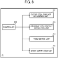
- FIG. 8 is a block diagram illustrating a functional configuration of the control system of the sheet processing apparatus 100.
- the sheet processing apparatus 100 includes the control device 300.
- the control device 300 has the same configuration as generally known information processing devices. That is, in the control device 300 according to the present embodiment of this disclosure, a central processing unit (CPU) 310, a random access memory (RAM) 320, a read only memory (ROM) 330, a control display panel 340, and an interface (I/F) 350 are connected via a bus 360.
- a cutter tool driver 351, a creasing tool driver 352, a tool moving driver 353, and a sheet conveyance driver 354 are connected to the I/F 350.
- the CPU 310 is a calculation unit and controls the operation of the entire information processing device.
- the RAM 320 is a volatile memory capable of high-speed reading and writing of information.
- the RAM 320 is used as a work area when the CPU 310 processes information.
- the ROM 330 is a read-only non-volatile memory to store firmware, control programs, and the like.
- the control display panel 340 is provided with a display screen that displays information to notify a user of the operation status of the sheet processing apparatus 100, for example.
- the control display panel 340 also provides an input interface via which a user inputs a set value to be used for the control.
- the I/F 350 transmits a control signal generated as a result of calculation of the CPU 310, to a specified driver, so that the driver causes a corresponding unit to perform each designated function.
- the cutter tool driver 351 controls the contact and separation operations in which the cutter tool 111 selectively contacts to and separates from the sheet 1.
- the creasing tool driver 352 controls the contact and separation operations in which the creasing tool 112 selectively contacts to and separates from the sheet 1.
- the tool moving driver 353 controls rotational movement of the X-axis drive motor 121 in the forward and reverse directions.
- the sheet conveyance driver 354 controls respective rotational operations of the first facing roller 131 and the second facing roller 132 and rotational operations of the pairs of conveyance rollers 150.
- the CPU 310 performs calculation according to the program stored in the ROM 330, thereby constructing a software controller.
- a combination of the software controller thus constructed and the hardware constructs functional blocks that implement functions of the sheet processing apparatus 100 according to the present embodiment is formed (see FIG. 8 ).
- a control unit 31 is achieved by the control device 300 of the sheet processing apparatus 100 and includes a controller 311 that controls the whole operations of the sheet processing apparatus 100, a cutter tool contact separation unit 312, a creasing tool contact separation unit 313, a tool moving unit 314, and a sheet conveyance unit 315.
- the tool moving unit 314 controls the processing tools 105 along the X-axis (the X direction), specifically, the moving direction, the moving amount, the moving speed, and timings of start and stop of movements of the processing tools 105 along the X-axis (the X direction).
- the sheet conveyance unit 315 controls the sheet 1 along the Y-axis (the Y direction), specifically, the moving direction (the conveyance direction), the moving amount, the moving speed, and timings of start and stop of movements of the sheet 1 along the Y-axis (the Y direction).
- the cutter tool contact separation unit 312 causes the cutter tool 111 to contact, press, or separate from the sheet 1 at a given timing.
- the creasing tool contact separation unit 313 causes the creasing tool 112 to contact, press, or separate from the sheet 1 at a given timing.
- the control unit 31 including a control program executed by the CPU 310 configures the above-described function units, so that the function units perform the control operations.
- the cutter tool 111 and the creasing tool 112 are moved while conveying the sheet 1, so as to selectively perform the contact and separation operations.
- the contact and separation operations while a given trajectory in the two-dimensional area is drawn on the sheet 1, the crease process is performed to the sheet 1 at a desired position or positions and the cut process is performed to cut the sheet 1 to a desired shape.
- the first facing roller 131 that includes a tool opposing face (tool facing portion) to face the cutter tool 111 and the second facing roller 132 that includes the tool opposing face (tool facing portion) to face the creasing tool 112 are rollers, each of which including an elastic body represented by silicon rubber and ethylene propylene (EP) rubber. That is, the tool opposing face of the first facing roller 131 and the tool opposing face of the second facing roller 132 are made of elastic bodies.
- the processing tools 105 performs sheet processing (first processing) to the sheet 1 in a direction orthogonal to the conveyance direction of the sheet 1
- the first facing roller 131 and the second facing roller 132 are held not to rotate, in other words, held not to move the first facing roller 131 and the second facing roller 132.
- the tool facing device 130 including the first facing roller 131 and the second facing roller 132 is immovable when a moving direction of the processing tools 105 relative to the sheet 1 is orthogonal to conveyance direction of the sheet 1.
- the sheet processing apparatus 100 when the sheet processing (the second processing) is performed to the sheet 1 in the direction other than the direction orthogonal to the conveyance direction of the sheet 1, that is, when the sheet processing is performed to the sheet 1 in directions including the conveyance direction of the sheet 1, at least the first facing roller 131 facing the cutter tool 111 rotates so that the tool opposing face moves around at the same speed as the conveying speed of the sheet 1.
- the moving direction of the tool facing device 130 including the first facing roller 131 is directed other than the direction orthogonal to the conveyance direction of the sheet 1, the tool facing device 130 moves in synchrony with conveyance of the sheet 1.
- the first facing roller 131 In a case in which the first facing roller 131 does not rotate in synchrony with the conveying speed of the sheet 1, since the sheet 1 and the first facing roller 131 contact each other over the entire region in the width direction of the sheet 1, the first facing roller 131 hinders conveyance of the sheet 1.
- the sheet conveyance force of the sheet 1 needs to be increased, which results in an increase in size of the whole sheet processing apparatus 100 or allowance of variation of the conveying speed of the sheet 1.
- the processing accuracy When the conveyance speed of the sheet 1 varies, the processing accuracy also varies, and therefore the size of the whole sheet processing apparatus 100 has to be increased.
- the first facing roller 131 rotates in synchrony with movement of the sheet 1, thereby assisting conveyance of the sheet 1 in the sheet processing and achieving a reduction in size of the sheet processing apparatus 100 and the highly accurate sheet processing of the sheet 1 with a given two-dimensional trajectory.
- FIG. 9 is an enlarged side view illustrating the tip of the creasing tool 112 of the sheet processing apparatus 100.
- a tip member 112a is attached to the tip of the creasing tool 112.
- the tip member 112a is a member having a spherical surface and is held at the tip of the creasing tool 112.
- the tip member 112a contacts and presses the second facing roller 132.
- the surface of the second facing roller 132 has elasticity. Therefore, when the second facing roller 132 is pressed by the tip member 112a, the surface of the second facing roller 132 is recessed.
- the creasing tool 112 moves to the sheet 1 relatively in the two-dimensional direction.
- the crease process providing the trajectory including given free-form curves is performed to the sheet 1.
- the tip member 112a moves in a direction with low friction in accordance with a relative moving direction of the sheet 1, so that the friction of movement of the creasing tool 112 is reduced when the sheet processing (the crease process) is performed by the creasing tool 112.
- the tip member 112a is not limited to a member having a spherical surface but may be a spherical tip member such as the tip of a ballpoint pen that is a rotatable tip freely rotatable in given directions.
- the creasing tool 112 moves with lower friction. Accordingly, in a case in which the tip member 112a is formed of a ball-shaped member, the friction of movement of the creasing tool 112 generated when the crease process is performed by the creasing tool 112 is further reduced.
- a pencil or a pen tool such as a ballpoint pen using ink may be used as the tip member 112a.
- the creasing tool 112 draws (forms) an image including free-form curves or visible lines such as ruled lines on the sheet 1 with a given trajectory.
- FIG. 10 including FIGS. 10(a) and 10(b) is an enlarged side view of the tip of the cutter tool 111.
- FIG. 10(a) illustrates an enlarged side view of the tip of the cutter tool 111 when the cutter tool 111 performs through cutting
- FIG. 10(b) illustrates an enlarged side view of the tip of the cutter tool 111 when the cutter tool 111 performs half cutting.
- a cutter blade 111a is held at the tip of the cutter tool 111.
- the cutter blade 111a is held so that the amount of protrusion may be changed.
- the cutter tool contact separation unit 312 controls the amount of protrusion of the cutter blade 111a in the thickness direction of the sheet 1.
- the cutter tool 111 cuts the sheet 1 in the thickness direction of the sheet 1.
- the cutter tool 111 cuts the releasable seal layer 1a alone, as illustrated in FIG. 10(b) .
- the cutter tool 111 cuts a part of the sheet 1 in the thickness direction of the sheet 1.
- the cutter tool 111 cuts the entire sheet 1 in the thickness direction of the sheet 1, as illustrated in FIG. 10(a) .
- the amount of protrusion of the tip of the cutter blade 111a is controlled intermittently between the amount corresponding to the thickness of the releasable seal layer 1a and the amount corresponding to the sum of the thickness of the releasable seal layer 1a and the thickness of the mount layer 1b, so as to provide a cutting portion and a non-cutting portion intermittently to the sheet 1. That is, the cutter tool 111 provides a cutting portion and a non-cutting portion intermittently to the sheet 1 in the thickness direction of the sheet 1.
- the cutter tool 111 when the cutter tool 111 is used when performing sheet processing to the sheet 1, while the cutter blade 111a moves in a direction in accordance with the relative moving direction of the sheet 1, the cutter tool 111 performs half cutting or through cutting, including free-form curves with a given trajectory, and perforation.
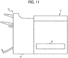
- FIG. 11 is a side view illustrating the external appearance of an image forming system 10 according to an embodiment of this disclosure.
- the sheet processing apparatus 100 described above is applicable as a stand-alone apparatus but may be included in the image forming system 10.
- the image forming system 10 includes an image forming apparatus 11 and a post-processing device 13.
- the image forming apparatus 11 includes a media feeding device 12.
- the image forming apparatus 11 forms a given image on a sheet 1 fed from the media feeding device 12 and conveys the sheet 1 toward the post-processing device 13.
- the image forming apparatus 11 is an apparatus that attaches material (such as liquid ink and toner) to form an image onto the sheet 1 that functions as a recording medium and that relates to, for example, electrophotographic printing, inkjet printing, and screen printing.
- the sheet processing apparatus 100 In a case in which the sheet processing apparatus 100 is provided in the post-processing device 13, after the image forming apparatus 11 forms an image on the sheet 1, the sheet processing apparatus 100 performs the first processing and the second processing, as described above, to convey the processed sheet 1.
- Processing circuitry includes a programmed processor, as a processor includes circuitry.
- a processing circuit also includes devices such as an application specific integrated circuit (ASIC), digital signal processor (DSP), field programmable gate array (FPGA), and conventional circuit components arranged to perform the recited functions.
- ASIC application specific integrated circuit
- DSP digital signal processor
- FPGA field programmable gate array
Landscapes
- Engineering & Computer Science (AREA)
- Mechanical Engineering (AREA)
- Folding Of Thin Sheet-Like Materials, Special Discharging Devices, And Others (AREA)
- Handling Of Sheets (AREA)
- Details Of Cutting Devices (AREA)
- Control Of Cutting Processes (AREA)
- Physics & Mathematics (AREA)
- General Physics & Mathematics (AREA)
Abstract
A sheet processing apparatus (100) includes a sheet conveyor (150) configured to convey a sheet (1), a processing tool (105) configured to perform processing to the sheet (1), a tool contact separation device (110) configured to contact and separate the processing tool (105) with respect to the sheet (1), a tool moving device (120) configured to move the processing tool (105) in a direction intersecting a conveyance direction of the sheet (1), and a tool facing device (130) including a tool facing portion (131, 132) disposed at a position facing the processing tool (105) via the sheet (1). The tool facing device (130) is configured to move to change the tool facing portion (131, 132) in accordance with a relative moving directions of the sheet (1) with respect to the processing tool (105) when the processing tool (105) performs the processing to the sheet (1).
Description
- This disclosure relates to a sheet processing apparatus and an image forming system incorporating the sheet processing apparatus.
- Various types of sheet processing apparatuses are known to perform a cut process and a crease process to a sheet. Such a sheet processing apparatus is used to create the processing patterns of stickers, cards, or box-shaped 3D objects, from a sheet on which an image or design pattern is printed.
- It is known there are various types of sheet processing apparatuses. For example, a flatbed type sheet processing apparatus fixes a sheet on a table provided on the apparatus, and causes a cutter tool and a creasing tool, which are processing tools, to selectively contact with pressure to the sheet or separate from the sheet while moving the cutter tool and the creasing tool over the sheet in a two-dimensional area. By so doing, a two-dimensional processing is provided to the sheet along a given trajectory while the sheet is fixed on the surface of the table.
- On the other hand, a conveyance type sheet processing apparatus is provided with a pair of sheet conveying rollers to convey a sheet in a given direction, in addition to the same processing tools as the processing tools provided in the flatbed type sheet processing apparatus. The conveyance type sheet processing apparatus moves the processing tools in a direction orthogonal to the conveyance direction of the sheet while conveying the sheet. By relatively conveying the sheet and moving the processing tool, the conveying type sheet processing apparatus causes the processing tool to selectively contact the sheet with pressure or separate from the sheet. By so doing, the processing tool performs the processing in the two-dimensional area along a given trajectory of the processing tool to the sheet.
- Since the conveyance type sheet processing apparatus does not include a table having a surface larger than a sheet, the conveyance type sheet processing apparatus is more preferable to enhance a reduction in size of the sheet processing apparatus. However, instead of the table having the surface larger than a sheet, the conveyance type sheet processing apparatus may need to include a facing member to face the processing tool, so that the facing member functions as a receiving member to prevent deformation of the sheet due to contact and application of pressure of the cutter tool and the creasing tool to the sheet. The facing member includes an elastic member such as a cutter mat. Note that, in a case in which the facing member is disposed facing the cutter tool, a fine groove shape member that meshes with the cutter blade may be used instead of the cutter mat.
- The facing member is provided at a given position so as not to deviate from the processing tool. Therefore, the tool facing position (the tool opposing face) of the facing member facing the processing tool is likely to be cut or pressed by the processing tool each time the processing is performed. Due to the cutting or pressing by the pressing tool, the facing member deteriorates at the given position (the tool facing position) alone. As a result, the tool opposing face of the facing member at the tool facing position is broken or the elasticity of the facing member deteriorates. The breakage of the facing member or the deterioration in the elasticity of the facing member causes deterioration in function as the facing member. If the elasticity of the facing member deteriorates, it is difficult to receive the sheet properly in the processing, which may adversely affect on the processing accuracy with respect to the sheet.
- Regrading the facing member provided to face the processing tool, there is a known technique in which a facing member is rotated according to the number of processes to shift the position (the tool facing position) to receive the processing tool, so as to enhance the durability of the facing member (see
JP 2004-114198-A - The technique disclosed in
JP 2004-114198-A JP 2004-114198-A JP 2004-114198-A - Further, in the technique disclosed in
JP 2004-114198-A - In view of the above-described disadvantages, an object of this disclosure is to provide a sheet processing sheet processing apparatus, which is capable of performing a process to a sheet in a two-dimensional area, to enhance the durability of a tool facing member disposed at a tool facing position facing the processing tool via the sheet.
- At least one aspect of this disclosure, a novel sheet processing apparatus includes a sheet conveyor, a processing tool, a tool contact separation device, a tool moving device, and a tool facing device. The sheet conveyor is configured to convey a sheet. The processing tool is configured to perform processing to the sheet. The tool contact separation device is configured to contact and separate the processing tool with respect to the sheet. The tool moving device is configured to move the processing tool in a direction intersecting a conveyance direction of the sheet. The tool facing device includes a tool facing portion disposed at a position facing the processing tool via the sheet. The tool facing device is configured to move to change the tool facing portion in accordance with a relative moving direction of the sheet with respect to the processing tool when the processing tool performs the processing to the sheet.
- Further, at least one aspect of this disclosure, an image forming system includes an image forming apparatus configured to form an image on a sheet, and the above-described sheet processing apparatus configured to process the sheet with the image formed by the image forming apparatus.
- According to this disclosure, the sheet processing apparatus that is capable of performing a process to a sheet in a two-dimensional area enhances the durability of the tool facing member disposed at a too facing position facing the processing tool via the sheet.
- Exemplary embodiments of this disclosure will be described in detail based on the following figures, wherein:
-
FIG. 1 is a perspective view illustrating a sheet processing apparatus according to an embodiment of this disclosure; -
FIG. 2 is a cross-sectional view illustrating the sheet processing apparatus; -
FIG. 3 is a perspective view illustrating the main part of the sheet processing apparatus; -
FIG. 4 is an enlarged side view illustrating a part of the main part of the sheet processing apparatus; -
FIG. 5 is an enlarged plan view illustrating a part of the main part of the sheet processing apparatus; -
FIG. 6 is an enlarged perspective view illustrating a part of the main part of the sheet processing apparatus; -
FIG. 7 is a block diagram illustrating a control configuration of the sheet processing apparatus; -
FIG. 8 is a functional block diagram illustrating a functional configuration of the sheet processing apparatus; -
FIG. 9 is an enlarged side view illustrating a part of a processing tool provided in the sheet processing apparatus; -
FIG. 10 includingFIGS. 10(a) and 10(b) is an enlarged side view illustrating a part of another processing tool provided in the sheet processing apparatus, whereFIG. 10(a) illustrates an enlarged side view of a tip of a cutter tool when the cutter tool performs through cutting, andFIG. 10(b) illustrates an enlarged side view of the tip of the cutter tool when the cutter tool performs half cutting; and -
FIG. 11 is a side view illustrating an image forming system according to an embodiment of this disclosure. - The accompanying drawings are intended to depict embodiments of the present disclosure and should not be interpreted to limit the scope thereof. The accompanying drawings are not to be considered as drawn to scale unless explicitly noted.
- It will be understood that if an element or layer is referred to as being "on," "against," "connected to" or "coupled to" another element or layer, then it can be directly on, against, connected or coupled to the other element or layer, or intervening elements or layers may be present. In contrast, if an element is referred to as being "directly on," "directly connected to" or "directly coupled to" another element or layer, then there are no intervening elements or layers present. Like numbers referred to like elements throughout. As used herein, the term "and/or" includes any and all combinations of one or more of the associated listed items.
- Spatially relative terms, such as "beneath," "below," "lower," "above," "upper" and the like may be used herein for ease of description to describe one element or feature's relationship to another element(s) or feature(s) as illustrated in the figures. It will be understood that the spatially relative terms are intended to encompass different orientations of the device in use or operation in addition to the orientation depicted in the figures. For example, if the device in the figures is turned over, elements describes as "below" or "beneath" other elements or features would then be oriented "above" the other elements or features. Thus, term such as "below" can encompass both an orientation of above and below. The device may be otherwise oriented (rotated 90 degrees or at other orientations) and the spatially relative descriptors herein interpreted accordingly.
- The terminology used herein is for describing particular embodiments and examples and is not intended to be limiting of exemplary embodiments of this disclosure. As used herein, the singular forms "a," "an," and "the" are intended to include the plural forms as well, unless the context clearly indicates otherwise. It will be further understood that the terms "includes" and/or "including," when used in this specification, specify the presence of stated features, integers, steps, operations, elements, and/or components, but do not preclude the presence or addition of one or more other features, integers, steps, operations, elements, components, and/or groups thereof.
- Referring now to the drawings, embodiments of the present disclosure are described below. In the drawings for explaining the following embodiments, the same reference codes are allocated to elements (members or components) having the same function or shape and redundant descriptions thereof are omitted below.
- Hereinafter, embodiments of a sheet processing apparatus according to the present embodiment is described with reference to the drawings.
-
FIG. 1 is a perspective view illustrating the external appearance of asheet processing apparatus 100 according to an embodiment of this disclosure. - As illustrated in
FIG. 1 , thesheet processing apparatus 100 includes asheet receiver tray 101 and asheet transfer tray 102. Thesheet receiver tray 101 functions as a sheet receiving port via which asheet 1 that functions as a sheet-like processing target member and a sheet member is conveyed to thesheet processing apparatus 100. Thesheet transfer tray 102 functions as a sheet transfer port of the processedsheet 1 after processing. Thesheet 1 is processed while being conveyed in a direction indicated by arrow Y (Y direction) inFIG. 1 . - Note that, as illustrated in
FIG. 1 , thesheet processing apparatus 100 further includes acontrol device 300 that controls the whole operations of thesheet processing apparatus 100. - Here, coordinate systems used to describe the present embodiment are defined.
- A Y direction is a direction in which the
sheet 1 before processing is conveyed to thesheet processing apparatus 100 and thesheet 1 after processing is conveyed from thesheet processing apparatus 100. An X direction is a direction that intersects the Y direction and corresponds to the width direction of the sheet 1 (the width direction of the sheet processing apparatus 100). A Z direction is a direction that intersects the Y direction and the X direction and corresponds to the direction of height of thesheet processing apparatus 100. Note that the embodiment is explained with an example in which the X direction, the Y direction, and the Z direction are orthogonal to each other. Accordingly, the phrase "conveyance direction of thesheet 1" in the present embodiment corresponds to movement of thesheet 1 in the Y direction. -
FIG. 2 is a cross-sectional view illustrating the internal configuration of thesheet processing apparatus 100.FIG. 2 is the cross-sectional view of a plane Y-Z of thesheet processing apparatus 100 inFIG. 1 . - As illustrated in
FIG. 2 , thesheet processing apparatus 100 includesprocessing tools 105, a toolcontact separation device 110, atool moving device 120, and atool facing device 130. Thesheet processing apparatus 100 further includes pairs ofconveyance rollers 150 that function as a sheet conveyor or conveyance members to reciprocally convey thesheet 1 toward theprocessing tools 105. The pairs ofconveyance rollers 150 include a first pair ofconveyance rollers 151 and a second pair ofconveyance rollers 152. InFIG. 2 , the first pair ofconveyance rollers 151 alone is depicted from the pairs ofconveyance rollers 150. The first pair ofconveyance rollers 151 is disposed on the sheet receiving port side. - The
processing tools 105 are held by the toolcontact separation device 110 so that theprocessing tools 105 are disposed at respective positions facing thetool facing device 130 with thesheet 1 interposed between theprocessing tools 105 and thetool facing devices 130. - The tool
contact separation device 110 holds theprocessing tools 105 such as a cutter tool to perform a cut process to thesheet 1 and a creasing tool to perform a crease process to thesheet 1. Details of theprocessing tools 105 are described below. The toolcontact separation device 110 includes a tool moving mechanism for contact and separation of the processing tools to cause theprocessing tools 105 to contact to or separate from thesheet 1. - The
tool moving device 120 includes a tool moving mechanism for sheet processing (tool moving mechanism for contact and separation of the processing tools) to reciprocally move theprocessing tools 105 in the X direction when the sheet processing such as the cut process and the crease process is performed to thesheet 1. Note that, in the present embodiment, the X direction is a direction orthogonal to the Y direction that is the conveyance direction of thesheet 1, in other words, an orthogonal direction to the Y direction (the conveyance direction of the sheet 1). Note that the direction of height of thesheet processing apparatus 100 is defined as the Z direction as illustrated inFIGS. 1 and2 . Therefore, the X direction is the direction orthogonal to the conveyance direction of thesheet 1 and the direction of height of thesheet processing apparatus 100 and corresponds to the width direction of thesheet 1. - The
tool facing device 130 includes rollers that function as rotary members. The rollers include respective tool opposing faces (tool facing portions) disposed facing theprocessing tools 105. Each tool opposing face corresponds to a position to receive pressing force to thesheet 1 applied by theprocessing tool 105 corresponding to a process position at which theprocessing tool 105 contacts thesheet 1 when theprocessing tool 105 moves in the X direction in the sheet processing. In other words, the tool opposing face is located at a position at which the tool opposing face of thetool facing device 130 faces theprocessing tool 105 via thesheet 1 interposed between thetool facing device 130 and theprocessing tool 105. As illustrated inFIG. 2 , the tool opposing face of thetool facing device 130 corresponds to the same position as theprocessing tool 105 in the Y direction. In other words, the tool opposing face of thetool facing device 130 is disposed below theprocessing tool 105 in the vertical direction (the Z direction). Further, in other words, theprocessing tool 105 is disposed above the tool opposing face in the vertical direction (the Z direction) and is held not to move (that is, held to be immovable) in the Y direction. - The
sheet processing apparatus 100 performs the sheet processing by theprocessing tools 105 while thesheet 1 is conveyed in the Y direction. In the sheet processing, theprocessing tools 105 and the toolcontact separation device 110 move not in the Y direction to thetool facing device 130 but in the X direction to thetool facing device 130. While theprocessing tools 105 and the toolcontact separation device 110 move in the X direction, theprocessing tools 105 selectively contact to or separate from thesheet 1. With the above-described operation, thesheet processing apparatus 100 performs sheet processing while drawing a trajectory including given plane free curves on thesheet 1. -
FIG. 3 is a perspective view illustrating the main part of the internal configuration of thesheet processing apparatus 100.FIG. 4 is an enlarged side view illustrating theprocessing tools 105 and the toolcontact separation device 110 provided in the internal configuration of thesheet processing apparatus 100.FIG. 5 is an enlarged plan view illustrating a drive source of thetool moving device 120 of thesheet processing apparatus 100.FIG. 6 is an enlarged perspective view illustrating a movable holding mechanism of thetool moving device 120 of thesheet processing apparatus 100. Note that the pairs ofconveyance rollers 150 are not depicted inFIG. 3 . - First, a description is given of the configuration of the tool
contact separation device 110 with reference toFIGS. 3 and4 . - The tool
contact separation device 110 includes acutter tool 111, acreasing tool 112, afirst tool holder 113, asecond tool holder 114, a firstcontact separation actuator 115, and a secondcontact separation actuator 116. Thecutter tool 111 and thecreasing tool 112 are included in theprocessing tools 105. - The
cutter tool 111 that functions as a first processing tool is a cutter that contacts thesheet 1 to perform the cut process to thesheet 1. Thecreasing tool 112 that functions as a second processing tool is a creaser that presses thesheet 1 to perform the crease process to thesheet 1, in other words, to make a crease line or lines in the surface of thesheet 1. Thecutter tool 111 is retained above a first facingroller 131 that functions as a tool facing body in the vertical direction and is disposed facing the first facingroller 131. Thecreasing tool 112 is retained above a second facingroller 132 that functions as a tool facing body in the vertical direction and is disposed facing the second facingroller 132. - The
first tool holder 113 couples and retains the firstcontact separation actuator 115 and thecutter tool 111. Thesecond tool holder 114 couples and retains the secondcontact separation actuator 116 and thecreasing tool 112. - The first
contact separation actuator 115 and the secondcontact separation actuator 116 are coupled with each other by atool moving member 128. Details of thetool moving member 128 are described below. Thetool moving member 128 causes the toolcontact separation device 110 to retain the processing tools 105 (that is, thecutter tool 111 and the creasing tool 112) integrally to be movable in the X direction. The firstcontact separation actuator 115 and the secondcontact separation actuator 116 are solenoids. By supplying the power to the firstcontact separation actuator 115 and the secondcontact separation actuator 116, theprocessing tools 105 maintain in a pressing state in which the first facingroller 131 and the second facingroller 132 press thesheet 1. Therefore, by controlling the operations of the firstcontact separation actuator 115 and the secondcontact separation actuator 116, thecutter tool 111 and thecreasing tool 112 are controlled to selectively contact to or separate from thesheet 1. This contact and separation control controls the processing operation to thesheet 1. - As illustrated in
FIG. 4 , a first pair ofconveyance rollers 151 that functions as a conveyance body is disposed upstream from the toolcontact separation device 110 that retains theprocessing tools 105, in the Y direction. In addition, a second pair ofconveyance rollers 152 that functions as a conveyance body is disposed downstream from the toolcontact separation device 110 that retains theprocessing tools 105, in the Y direction. Thesheet 1 is conveyed in the Y direction by the pairs of conveyance rollers 150 (including the first pair ofconveyance rollers 151 and the second pair of conveyance rollers 152). After having been conveyed from the upstream side in the Y direction to thesheet processing apparatus 100, thesheet 1 is held by the first pair ofconveyance rollers 151. Due to rotation of the first pair ofconveyance rollers 151, thesheet 1 is conveyed below theprocessing tools 105 to be processed. Then, after the sheet processing is performed to thesheet 1, thesheet 1 is held by the second pair ofconveyance rollers 152 to be conveyed out from thesheet processing apparatus 100. - As illustrated in
FIG. 3 , the first facingroller 131 is disposed facing firstgripping rollers 133, each of which functions as a rotary body to rotate along with rotation of the first facingroller 131. To be more specific, one first gripping roller 133 (that is, a firstgripping roller 133a) is disposed facing the first facingroller 131 on one end side of the first facingroller 131 in the X direction and another first gripping roller 133 (that is, a firstgripping roller 133b) is disposed facing the first facingroller 131 on the opposite end side of the first facingroller 131 in the X direction. Further, a second facingroller 132 is disposed facing each secondgripping roller 134, each of which rotates along with rotation of the second facingroller 132. To be more specific, one second gripping roller 134 (that is, a secondgripping roller 134a) is disposed facing the second facingroller 132 on one end side of the second facingroller 132 in the X direction and another second gripping roller 134 (that is, a secondgripping roller 134b) is disposed facing the second facingroller 132 on the opposite end side of the second facingroller 132 in the X direction. Thesheet 1 is gripped by the first facingroller 131 and the firstgripping roller 133, both as conveyance bodies, and by the second facingroller 132 and the secondgripping roller 134, both as conveyance bodies, so that thesheet 1 is reciprocally moved (conveyed) in the Y direction. That is, when thesheet 1 is processed, thesheet 1 is conveyed by the first facingroller 131 and the firstgripping roller 133 and by the second facingroller 132 and the secondgripping roller 134, in addition to, by the first pair ofconveyance rollers 151 and the second pair ofconveyance rollers 152. - Next, a description is given of the configuration of the
tool moving device 120, with reference toFIGS. 3 ,5 , and6 . - The
tool moving device 120 includes anX-axis drive motor 121, anoutput timing pulley 122, afirst timing belt 123, areduction timing pulley 124, a firsttool moving pulley 125, asecond timing belt 126, a secondtool moving pulley 127, thetool moving member 128, and a tool movingguide shaft 129. - The
X-axis drive motor 121 is a drive source that is rotatable in both the forward direction and the reverse direction to move the toolcontact separation device 110 that retains thecutter tool 111 and thecreasing tool 112, in a direction intersecting the conveyance direction of the sheet 1 (the Y direction). The rotary shaft of theX-axis drive motor 121 is coupled with thereduction timing pulley 124 from theoutput timing pulley 122 via thefirst timing belt 123. - The
reduction timing pulley 124 is in contact with the firsttool moving pulley 125 via a gear portion that is molded as a single component. Accordingly, as theX-axis drive motor 121 drives to rotate thereduction timing pulley 124, the firsttool moving pulley 125 rotates via the gear portion. - As illustrated in
FIGS. 5 and6 , the firsttool moving pulley 125 and the secondtool moving pulley 127 as a pair together are coupled by thesecond timing belt 126. Therefore, thesecond timing belt 126 that is wound around the firsttool moving pulley 125 and the secondtool moving pulley 127 rotates along with rotation of the firsttool moving pulley 125. - The
tool moving member 128 holds thesecond timing belt 126 to fix at a given position of thesecond timing belt 126. Accordingly, as thesecond timing belt 126 rotates between the firsttool moving pulley 125 and the secondtool moving pulley 127, thetool moving member 128 also moves along with the rotation of thesecond timing belt 126. The tool movingguide shaft 129 is inserted through thetool moving member 128. The tool movingguide shaft 129 is disposed extending in the X direction and both end portions of the tool movingguide shaft 129 are fixed to a housing of thesheet processing apparatus 100. Therefore, along with rotation of thesecond timing belt 126, that is, along with rotation of theX-axis drive motor 121, thetool moving member 128 is guided by the tool movingguide shaft 129 to move in the X direction alone. Consequently, as theX-axis drive motor 121 rotates in the forward direction and the reverse direction, the toolcontact separation device 110 that is coupled with and fixed to thetool moving member 128 reciprocally moves in the direction (the X direction) intersecting the conveyance direction of thesheet 1. Accordingly, theprocessing tools 105 are held to be reciprocally movable in the direction (the X direction) intersecting the conveyance direction of thesheet 1. - Next, a description is given of the configuration of the
tool facing device 130, with reference toFIG. 3 . - The
tool facing device 130 includes the first facingroller 131, the second facingroller 132, the first gripping rollers 133 (that is, the firstgripping roller 133a and the firstgripping roller 133b), and the second gripping rollers 134 (that is, the secondgripping roller 134a and the secondgripping roller 134b). The first facingroller 131 and the second facingroller 132 are rotary members that rotate in both directions, which are the forward direction and the reverse direction, by a drive source such as an electric motor. The first facingroller 131 and the second facingroller 132 rotate (move) to convey thesheet 1 in synchrony with conveyance of thesheet 1 by the first pair ofconveyance rollers 151 and the second pair ofconveyance rollers 152. That is, the first facingroller 131, the second facing roller 32, the firstgripping rollers 133, and the secondgripping rollers 134 rotate together with the first pair ofconveyance rollers 151 and the second pair ofconveyance rollers 152. The first facingroller 131 and the second facingroller 132 are also drive rollers. The firstgripping rollers 133 and the secondgripping rollers 134 are driven rollers that rotate along with rotations of the drive rollers. - Each of the first
gripping rollers 133 is pressed (biased) by a biasing member in the -Z direction so as to be pressed against the first facingroller 131. Each of the secondgripping rollers 134 is pressed (biased) by a biasing member in the -Z direction so as to be pressed against the second facingroller 132. Therefore, the first facingroller 131 and the first gripping rollers 133 (that is, the firstgripping roller 133a and the firstgripping roller 133b) grip thesheet 1 while thesheet 1 is being processed. Further, the second facingroller 132 and the second gripping rollers 134 (that is, the secondgripping roller 134a and the secondgripping roller 134b) also grip thesheet 1 while thesheet 1 is being processed. Note that, inFIG. 3 , a part of the second gripping rollers 134 (that is, the secondgripping roller 134b) is hidden behind the toolcontact separation device 110, and therefore the secondgripping roller 134b is not depicted inFIG. 3 . - When processing the
sheet 1, as the first facingroller 131 and the second facingroller 132, both of which function as drive rollers, rotate in the forward and reverse rotations, thesheet 1 in the processing is reciprocally conveyed in the Y direction. That is, thetool facing device 130 is a conveying device that functions as a sheet conveyor that reciprocally conveys thesheet 1 in the Y direction. Due to the control of rotation of thetool facing device 130, thesheet 1 is reciprocally conveyed between thecutter tool 111 and the first facingroller 131 and between the creasingtool 112 and the second facingroller 132. - In the present embodiment, the pairs of
conveyance rollers 150, various rotary members, and theX-axis drive motor 121 are based on stepping motors. However, as long as the above-described operations are performed, the type of a drive source is not limited. Further, the firstcontact separation actuator 115 and the secondcontact separation actuator 116 are based on respective solenoids. However, as long as the above-described operations are performed, the type of a drive source is not limited. - Note that the present embodiment provides the configuration in which the
processing tools 105 and the tool contact separation mechanism (the tool contact separation device 110) are moved in the width direction of thesheet 1 by the tool process moving mechanism (the tool moving device 120). However, the sheet processing apparatus according to this disclosure is not limited to this configuration. For example, theprocessing tools 105 may contact to and separate from the tool process moving mechanism (the tool moving device 120) by the tool contact separation mechanism. Alternatively, a mechanism may move theprocessing tools 105 alone in the width direction of thesheet 1 and another mechanism may cause theprocessing tools 105 alone to contact to and separate from thesheet 1. - Next, a description is given of the control configuration of the
sheet processing apparatus 100 according to the present embodiment of this disclosure, with reference toFIGS. 7 and8 . -
FIG. 7 is a block diagram illustrating a hardware configuration of the control system of thesheet processing apparatus 100.FIG. 8 is a block diagram illustrating a functional configuration of the control system of thesheet processing apparatus 100. - As illustrated in
FIG. 7 , thesheet processing apparatus 100 includes thecontrol device 300. Thecontrol device 300 has the same configuration as generally known information processing devices. That is, in thecontrol device 300 according to the present embodiment of this disclosure, a central processing unit (CPU) 310, a random access memory (RAM) 320, a read only memory (ROM) 330, acontrol display panel 340, and an interface (I/F) 350 are connected via abus 360. Acutter tool driver 351, acreasing tool driver 352, atool moving driver 353, and asheet conveyance driver 354 are connected to the I/F 350. - The
CPU 310 is a calculation unit and controls the operation of the entire information processing device. TheRAM 320 is a volatile memory capable of high-speed reading and writing of information. TheRAM 320 is used as a work area when theCPU 310 processes information. TheROM 330 is a read-only non-volatile memory to store firmware, control programs, and the like. Thecontrol display panel 340 is provided with a display screen that displays information to notify a user of the operation status of thesheet processing apparatus 100, for example. Thecontrol display panel 340 also provides an input interface via which a user inputs a set value to be used for the control. - The I/
F 350 transmits a control signal generated as a result of calculation of theCPU 310, to a specified driver, so that the driver causes a corresponding unit to perform each designated function. Thecutter tool driver 351 controls the contact and separation operations in which thecutter tool 111 selectively contacts to and separates from thesheet 1. Thecreasing tool driver 352 controls the contact and separation operations in which thecreasing tool 112 selectively contacts to and separates from thesheet 1. Thetool moving driver 353 controls rotational movement of theX-axis drive motor 121 in the forward and reverse directions. Thesheet conveyance driver 354 controls respective rotational operations of the first facingroller 131 and the second facingroller 132 and rotational operations of the pairs ofconveyance rollers 150. - In the hardware configuration described above, the
CPU 310 performs calculation according to the program stored in theROM 330, thereby constructing a software controller. A combination of the software controller thus constructed and the hardware constructs functional blocks that implement functions of thesheet processing apparatus 100 according to the present embodiment is formed (seeFIG. 8 ). - As illustrated in
FIG. 8 , acontrol unit 31 is achieved by thecontrol device 300 of thesheet processing apparatus 100 and includes acontroller 311 that controls the whole operations of thesheet processing apparatus 100, a cutter toolcontact separation unit 312, a creasing toolcontact separation unit 313, atool moving unit 314, and asheet conveyance unit 315. - The
tool moving unit 314 controls theprocessing tools 105 along the X-axis (the X direction), specifically, the moving direction, the moving amount, the moving speed, and timings of start and stop of movements of theprocessing tools 105 along the X-axis (the X direction). - The
sheet conveyance unit 315 controls thesheet 1 along the Y-axis (the Y direction), specifically, the moving direction (the conveyance direction), the moving amount, the moving speed, and timings of start and stop of movements of thesheet 1 along the Y-axis (the Y direction). - The cutter tool
contact separation unit 312 causes thecutter tool 111 to contact, press, or separate from thesheet 1 at a given timing. The creasing toolcontact separation unit 313 causes thecreasing tool 112 to contact, press, or separate from thesheet 1 at a given timing. - The
control unit 31 including a control program executed by theCPU 310 configures the above-described function units, so that the function units perform the control operations. By performing these control operations, thecutter tool 111 and thecreasing tool 112 are moved while conveying thesheet 1, so as to selectively perform the contact and separation operations. By performing the contact and separation operations, while a given trajectory in the two-dimensional area is drawn on thesheet 1, the crease process is performed to thesheet 1 at a desired position or positions and the cut process is performed to cut thesheet 1 to a desired shape. - The first facing
roller 131 that includes a tool opposing face (tool facing portion) to face thecutter tool 111 and the second facingroller 132 that includes the tool opposing face (tool facing portion) to face thecreasing tool 112 are rollers, each of which including an elastic body represented by silicon rubber and ethylene propylene (EP) rubber. That is, the tool opposing face of the first facingroller 131 and the tool opposing face of the second facingroller 132 are made of elastic bodies. - Here, a detailed description is given of the operations of the
sheet processing apparatus 100. - When the
processing tools 105 performs sheet processing (first processing) to thesheet 1 in a direction orthogonal to the conveyance direction of thesheet 1, the first facingroller 131 and the second facingroller 132 are held not to rotate, in other words, held not to move the first facingroller 131 and the second facingroller 132. In other words, thetool facing device 130 including the first facingroller 131 and the second facingroller 132 is immovable when a moving direction of theprocessing tools 105 relative to thesheet 1 is orthogonal to conveyance direction of thesheet 1. - When sheet processing (second processing) is performed to the
sheet 1 in a direction other than the direction orthogonal to the conveyance direction of thesheet 1, the first facingroller 131 and the second facingroller 132 rotate in the conveyance direction of thesheet 1. By performing the operation controls as described above, the positions (portions) of the tool opposing faces of the first facingroller 131 and the second facingroller 132, at which theprocessing tools 105 are received, may be changed according to the conveyance direction of thesheet 1. As a result, when sheet processing is performed to thesheet 1 in the width direction while changing the positions of tool opposing faces of the first facingroller 131 and the second facingroller 132, the tool opposing faces are held not to move (in other words, held to be immovable) so that stable processing is performed. - In a case in which the tool opposing faces of the first facing
roller 131 and the second facingroller 132 of thesheet processing apparatus 100 according to the present embodiment are not moved in the above-described manner, the same portions of the first facingroller 131 and the second facing roller 132 (specified portions of the first facingroller 131 and the second facing roller 132) are continuously engaged with thecutter tool 111 and thecreasing tool 112. As a result, "settling" such as wear or deformation of the specific portions of the first facingroller 131 and the second facingroller 132 advances quickly, thereby deteriorating the durability of the first facingroller 131 and the second facingroller 132. - In this respect, with the
sheet processing apparatus 100 according to the present embodiment, when the sheet processing (the second processing) is performed to thesheet 1 in the direction other than the direction orthogonal to the conveyance direction of thesheet 1, that is, when the sheet processing is performed to thesheet 1 in directions including the conveyance direction of thesheet 1, at least the first facingroller 131 facing thecutter tool 111 rotates so that the tool opposing face moves around at the same speed as the conveying speed of thesheet 1. In other words, when the moving direction of thetool facing device 130 including the first facingroller 131 is directed other than the direction orthogonal to the conveyance direction of thesheet 1, thetool facing device 130 moves in synchrony with conveyance of thesheet 1. - In a case in which the first facing
roller 131 does not rotate in synchrony with the conveying speed of thesheet 1, since thesheet 1 and the first facingroller 131 contact each other over the entire region in the width direction of thesheet 1, the first facingroller 131 hinders conveyance of thesheet 1. When conveyance of thesheet 1 is hindered, the sheet conveyance force of thesheet 1 needs to be increased, which results in an increase in size of the wholesheet processing apparatus 100 or allowance of variation of the conveying speed of thesheet 1. When the conveyance speed of thesheet 1 varies, the processing accuracy also varies, and therefore the size of the wholesheet processing apparatus 100 has to be increased. In this respect, with thesheet processing apparatus 100 according to the present embodiment, the first facingroller 131 rotates in synchrony with movement of thesheet 1, thereby assisting conveyance of thesheet 1 in the sheet processing and achieving a reduction in size of thesheet processing apparatus 100 and the highly accurate sheet processing of thesheet 1 with a given two-dimensional trajectory. - Next, a description is given of the detailed configuration of the
creasing tool 112, with reference toFIG. 9 . -
FIG. 9 is an enlarged side view illustrating the tip of thecreasing tool 112 of thesheet processing apparatus 100. - A
tip member 112a is attached to the tip of thecreasing tool 112. Thetip member 112a is a member having a spherical surface and is held at the tip of thecreasing tool 112. Thetip member 112a contacts and presses the second facingroller 132. The surface of the second facingroller 132 has elasticity. Therefore, when the second facingroller 132 is pressed by thetip member 112a, the surface of the second facingroller 132 is recessed. - While the
sheet 1 is held between thetip member 112a of thecreasing tool 112 and the second facingroller 132, thecreasing tool 112 moves to thesheet 1 relatively in the two-dimensional direction. By so doing, the crease process providing the trajectory including given free-form curves is performed to thesheet 1. In the crease process, thetip member 112a moves in a direction with low friction in accordance with a relative moving direction of thesheet 1, so that the friction of movement of thecreasing tool 112 is reduced when the sheet processing (the crease process) is performed by thecreasing tool 112. - Note that the
tip member 112a is not limited to a member having a spherical surface but may be a spherical tip member such as the tip of a ballpoint pen that is a rotatable tip freely rotatable in given directions. In this case, since thetip member 112a rotates in the direction in accordance with the relative moving direction of thesheet 1 when the crease process is performed to thesheet 1, thecreasing tool 112 moves with lower friction. Accordingly, in a case in which thetip member 112a is formed of a ball-shaped member, the friction of movement of thecreasing tool 112 generated when the crease process is performed by thecreasing tool 112 is further reduced. - Further, a pencil or a pen tool such as a ballpoint pen using ink may be used as the
tip member 112a. In this case, in the crease process using thecreasing tool 112, while thetip member 112a of thecreasing tool 112 moves in the direction in accordance with the relative moving direction of thesheet 1, thecreasing tool 112 draws (forms) an image including free-form curves or visible lines such as ruled lines on thesheet 1 with a given trajectory. - Next, a description is given of the detailed configuration of the
cutter tool 111, with reference toFIG. 10 . -
FIG. 10 includingFIGS. 10(a) and 10(b) is an enlarged side view of the tip of thecutter tool 111. Specifically,FIG. 10(a) illustrates an enlarged side view of the tip of thecutter tool 111 when thecutter tool 111 performs through cutting, andFIG. 10(b) illustrates an enlarged side view of the tip of thecutter tool 111 when thecutter tool 111 performs half cutting. - A
cutter blade 111a is held at the tip of thecutter tool 111. Thecutter blade 111a is held so that the amount of protrusion may be changed. The cutter toolcontact separation unit 312 controls the amount of protrusion of thecutter blade 111a in the thickness direction of thesheet 1. In other words, thecutter tool 111 cuts thesheet 1 in the thickness direction of thesheet 1. For example, when thesheet 1 has layers including areleasable seal layer 1a and amount layer 1b, in a case in which the tip of thecutter blade 111a of thecutter tool 111 is protruded by the amount corresponding to the thickness of thereleasable seal layer 1a, thecutter tool 111 cuts thereleasable seal layer 1a alone, as illustrated inFIG. 10(b) . In other words, thecutter tool 111 cuts a part of thesheet 1 in the thickness direction of thesheet 1. - Further, in a case in which the tip of the
cutter blade 111a of thecutter tool 111 is protruded by the amount corresponding to the sum of the thickness of thereleasable seal layer 1a and the thickness of themount layer 1b, thecutter tool 111 cuts theentire sheet 1 in the thickness direction of thesheet 1, as illustrated inFIG. 10(a) . - In addition, the amount of protrusion of the tip of the
cutter blade 111a is controlled intermittently between the amount corresponding to the thickness of thereleasable seal layer 1a and the amount corresponding to the sum of the thickness of thereleasable seal layer 1a and the thickness of themount layer 1b, so as to provide a cutting portion and a non-cutting portion intermittently to thesheet 1. That is, thecutter tool 111 provides a cutting portion and a non-cutting portion intermittently to thesheet 1 in the thickness direction of thesheet 1. - Accordingly, when the
cutter tool 111 is used when performing sheet processing to thesheet 1, while thecutter blade 111a moves in a direction in accordance with the relative moving direction of thesheet 1, thecutter tool 111 performs half cutting or through cutting, including free-form curves with a given trajectory, and perforation. - Next, a description is given of an image forming system according to an embodiment of this disclosure, with reference to
FIG. 11 . -
FIG. 11 is a side view illustrating the external appearance of animage forming system 10 according to an embodiment of this disclosure. - The
sheet processing apparatus 100 described above is applicable as a stand-alone apparatus but may be included in theimage forming system 10. - The
image forming system 10 includes animage forming apparatus 11 and apost-processing device 13. Theimage forming apparatus 11 includes amedia feeding device 12. Theimage forming apparatus 11 forms a given image on asheet 1 fed from themedia feeding device 12 and conveys thesheet 1 toward thepost-processing device 13. Note that theimage forming apparatus 11 is an apparatus that attaches material (such as liquid ink and toner) to form an image onto thesheet 1 that functions as a recording medium and that relates to, for example, electrophotographic printing, inkjet printing, and screen printing. - In a case in which the
sheet processing apparatus 100 is provided in thepost-processing device 13, after theimage forming apparatus 11 forms an image on thesheet 1, thesheet processing apparatus 100 performs the first processing and the second processing, as described above, to convey the processedsheet 1. - The present disclosure is not limited to specific embodiments described above, and numerous additional modifications and variations are possible in light of the teachings within the technical scope of the appended claims. It is therefore to be understood that, the disclosure of this patent specification may be practiced otherwise by those skilled in the art than as specifically described herein, and such, modifications, alternatives are within the technical scope of the appended claims. Such embodiments and variations thereof are included in the scope and gist of the embodiments of the present disclosure and are included in the embodiments described in claims and the equivalent scope thereof.
- The above-described embodiments are illustrative and do not limit the present invention. Thus, numerous additional modifications and variations are possible in light of the above teachings. For example, elements and/or features of different illustrative embodiments may be combined with each other and/or substituted for each other within the scope of this disclosure.
- Any one of the above-described operations may be performed in various other ways, for example, in an order different from the one described above.
- Each of the functions of the described embodiments may be implemented by one or more processing circuits or circuitry. Processing circuitry includes a programmed processor, as a processor includes circuitry. A processing circuit also includes devices such as an application specific integrated circuit (ASIC), digital signal processor (DSP), field programmable gate array (FPGA), and conventional circuit components arranged to perform the recited functions.
Claims (15)
- A sheet processing apparatus (100) comprising:a sheet conveyor (150) configured to convey a sheet (1);a processing tool (105) configured to perform processing to the sheet (1);a tool contact separation device (110) configured to contact and separate the processing tool (105) with respect to the sheet (1);a tool moving device (120) configured to move the processing tool (105) in a direction intersecting a conveyance direction of the sheet (1); anda tool facing device (130) including a tool facing portion (131, 132) disposed at a position facing the processing tool (105) via the sheet (1),the tool facing device (130) configured to move to change the tool facing portion (131, 132) in accordance with a relative moving direction of the sheet (1) with respect to the processing tool (105) when the processing tool (105) performs the processing to the sheet (1).
- The sheet processing apparatus (100) according to claim 1,
wherein the tool facing device (130) is configured not to move the tool facing portion (131, 132) when a moving direction of the processing tool (105) with respect to the sheet (1) is orthogonal to the conveyance direction of the sheet (1). - The sheet processing apparatus (100) according to claim 1 or claim 2,
wherein the tool facing device (130) is configured to move the tool facing portion (131, 132) in synchrony with conveyance of the sheet (1) when a moving direction of the processing tool (105) with respect to the sheet (1) is a direction other than a direction orthogonal to the conveyance direction of the sheet (1). - The sheet processing apparatus (100) according to any one of claims 1 to 3,
wherein the tool facing portion (131, 132) includes an elastic body. - The sheet processing apparatus (100) according to any one of claims 1 to 4, further comprising a rotary body (133, 134) disposed facing the tool facing portion of the tool facing portion (131, 132).
- The sheet processing apparatus (100) according to claim 5,
wherein the rotary body (133, 134) is configured to convey the sheet (1) in the conveyance direction of the sheet (1). - The sheet processing apparatus (100) according to claim 6,
wherein the rotary body (133, 134) is configured to rotate together with the sheet conveyor (150). - The sheet processing apparatus (100) according to any one of claims 1 to 7,
wherein the processing tool (105) includes at least one of:a creaser (112) configured to make a crease in a surface of the sheet (1); anda cutter (111) configured to cut the sheet (1). - The sheet processing apparatus according to any one of claims 1 to 7,
wherein the processing tool (105) includes:a creaser (112) disposed facing the tool facing portion (131, 132), the creaser (112) configured to make a crease in the surface of the sheet (1); anda cutter (111) disposed facing the tool facing portion (131, 132), the cutter (111) configured to cut the sheet (1). - The sheet processing apparatus (100) according to claim 8 or claim 9,
wherein the creaser (112) includes a spherical tip. - The sheet processing apparatus (100) according to claim 8 or claim 9,
wherein the creaser (112) includes a rotatable tip. - The sheet processing apparatus (100) according to claim 8 or claim 9,
wherein the creaser (112) is configured to form a visible line on the sheet (1). - The sheet processing apparatus according to any one of claims 8 to 12,
wherein the cutter (111) is configured to cut the sheet (1) in a thickness direction of the sheet (1). - The sheet processing apparatus (100) according to any one of claims 8 to 12,
wherein the cutter (111) is configured to cut a part of the sheet (1) in a thickness direction of the sheet (1). - An image forming system (10) comprising:an image forming apparatus (11) configured to form an image on a sheet (1); andthe sheet processing apparatus (100) according to any one of claims 1 to 14, configured to process the sheet (1) with the image formed by the image forming apparatus (11).
Applications Claiming Priority (1)
| Application Number | Priority Date | Filing Date | Title |
|---|---|---|---|
| JP2019148121A JP7322582B2 (en) | 2019-08-09 | 2019-08-09 | Sheet processing equipment, image forming system |
Publications (1)
| Publication Number | Publication Date |
|---|---|
| EP3789329A1 true EP3789329A1 (en) | 2021-03-10 |
Family
ID=71846238
Family Applications (1)
| Application Number | Title | Priority Date | Filing Date |
|---|---|---|---|
| EP20188301.4A Withdrawn EP3789329A1 (en) | 2019-08-09 | 2020-07-29 | Sheet processing apparatus and image forming system incorporating the sheet processing apparatus |
Country Status (4)
| Country | Link |
|---|---|
| US (1) | US11530107B2 (en) |
| EP (1) | EP3789329A1 (en) |
| JP (1) | JP7322582B2 (en) |
| CN (1) | CN112340514A (en) |
Families Citing this family (18)
| Publication number | Priority date | Publication date | Assignee | Title |
|---|---|---|---|---|
| JP7598534B2 (en) | 2020-04-15 | 2024-12-12 | 株式会社リコー | SHEET PEELING DEVICE, LAMINATING DEVICE, IMAGE FORMING DEVICE, AND IMAGE FORMING SYSTEM |
| JP7549792B2 (en) | 2020-04-23 | 2024-09-12 | 株式会社リコー | Image forming apparatus and image forming system |
| US11261043B2 (en) | 2020-05-07 | 2022-03-01 | Ricoh Company, Ltd. | Sheet processing device, sheet laminator, image forming apparatus, and image forming system |
| US11292240B2 (en) | 2020-05-08 | 2022-04-05 | Ricoh Company, Ltd. | Sheet processing device, sheet laminator, image forming apparatus, and image forming system |
| JP7435232B2 (en) | 2020-05-13 | 2024-02-21 | 株式会社リコー | Sheet processing equipment, lamination processing equipment, image forming equipment, and image forming systems |
| CN113666180B (en) | 2020-05-13 | 2023-01-31 | 株式会社理光 | Sheet processing apparatus, lamination processing apparatus, image forming apparatus, and image forming system |
| US11801705B2 (en) | 2020-06-12 | 2023-10-31 | Ricoh Company, Ltd. | Image forming system, image forming apparatus, and sheet processing device |
| JP7512707B2 (en) | 2020-06-29 | 2024-07-09 | 株式会社リコー | SHEET PROCESSING APPARATUS, LAMINATING APPARATUS, IMAGE FORMING APPARATUS, AND IMAGE FORMING SYSTEM |
| JP7459684B2 (en) | 2020-06-29 | 2024-04-02 | 株式会社リコー | Lamination processing device, image forming device, and image forming system |
| JP7514441B2 (en) | 2020-07-07 | 2024-07-11 | 株式会社リコー | Image forming apparatus and image forming system |
| JP7540281B2 (en) * | 2020-10-09 | 2024-08-27 | コニカミノルタ株式会社 | Post-processing system, drilling member abnormality determination device and program |
| US12240726B2 (en) | 2021-02-16 | 2025-03-04 | Ricoh Company, Ltd. | Sheet processing apparatus, image forming apparatus, and image forming system |
| JP7625908B2 (en) | 2021-03-11 | 2025-02-04 | 株式会社リコー | SHEET PROCESSING APPARATUS, LAMINATING APPARATUS, IMAGE FORMING APPARATUS, AND IMAGE FORMING SYSTEM |
| JP7625912B2 (en) | 2021-03-12 | 2025-02-04 | 株式会社リコー | SHEET PROCESSING APPARATUS, LAMINATING APPARATUS, IMAGE FORMING APPARATUS, AND IMAGE FORMING SYSTEM |
| JP7661729B2 (en) | 2021-03-12 | 2025-04-15 | 株式会社リコー | Lamination processing device, image forming device and image forming system |
| JP7727167B2 (en) | 2021-04-16 | 2025-08-21 | 株式会社リコー | Sheet processing apparatus, image forming apparatus, and image forming system |
| JP7737620B2 (en) | 2021-06-01 | 2025-09-11 | 株式会社リコー | Sheet processing apparatus, image forming apparatus, and image forming system |
| JP7647394B2 (en) | 2021-06-30 | 2025-03-18 | 株式会社リコー | Image forming system |
Citations (5)
| Publication number | Priority date | Publication date | Assignee | Title |
|---|---|---|---|---|
| US6190297B1 (en) * | 1998-12-04 | 2001-02-20 | Gerber Scientific Products, Inc. | Apparatus for cutting and creasing sheet material |
| JP2004114198A (en) | 2002-09-25 | 2004-04-15 | Canon Finetech Inc | Sheet cutting apparatus, and sheet processing apparatus and image processing apparatus equipped with the same |
| US20050223865A1 (en) * | 2004-04-08 | 2005-10-13 | Kiefel Extrusion Gmbh | Transporting roller for webs of material |
| US20130269495A1 (en) * | 2012-04-11 | 2013-10-17 | Xerox Corporation | Blade clearance groove for cutting plotter |
| US20140151949A1 (en) * | 2012-12-05 | 2014-06-05 | Seiko Epson Corporation | Liquid discharging apparatus |
Family Cites Families (28)
| Publication number | Priority date | Publication date | Assignee | Title |
|---|---|---|---|---|
| US3735660A (en) * | 1970-07-31 | 1973-05-29 | Gerber Garment Technology Inc | Device for cutting sheet material |
| US4467525A (en) * | 1982-07-26 | 1984-08-28 | Gerber Scientific Products, Inc. | Automated sign generator |
| JPS59143694U (en) * | 1983-03-14 | 1984-09-26 | 東洋電機製造株式会社 | Automatic drawing cutting machine press ruling device |
| JPH05138594A (en) * | 1991-11-20 | 1993-06-01 | Gunze Ltd | Device for cutting fabric |
| JPH07328987A (en) * | 1994-06-08 | 1995-12-19 | Graphtec Corp | Medium transfer type plotter |
| JPH081584A (en) * | 1994-06-24 | 1996-01-09 | Mutoh Ind Ltd | Cutting plotter |
| US5868507A (en) * | 1997-04-09 | 1999-02-09 | Gerber Scientific Products, Inc. | Plotter having sprockets for driving sheets relative to a tool carriage and a fixed sheet support extending between the sprockets |
| US6840898B2 (en) | 1998-10-09 | 2005-01-11 | Emsize Ab | Apparatus for the positioning of a tool or a tool holder in a machine designed for processing a sheet material |
| JP4108218B2 (en) | 1999-03-23 | 2008-06-25 | ホリゾン・インターナショナル株式会社 | Saddle folding machine |
| US6506324B1 (en) * | 2000-03-27 | 2003-01-14 | Gerber Scientific Products, Inc. | Method for embossing a sheet-type work material |
| JP4828723B2 (en) | 2001-05-22 | 2011-11-30 | グラフテック株式会社 | Cutting plotter with crease function |
| JP3853623B2 (en) | 2001-09-27 | 2006-12-06 | 株式会社テクナ | 2D cutting device |
| US20030118689A1 (en) * | 2001-12-21 | 2003-06-26 | Carlson Christopher Robert | Embossing system |
| US6926400B2 (en) * | 2002-10-31 | 2005-08-09 | Hewlett-Packard Development Company, L.P. | Media incising printer |
| JP2005007721A (en) | 2003-06-18 | 2005-01-13 | Techno Japan:Kk | Ruled line forming implement |
| JP4906540B2 (en) | 2007-03-05 | 2012-03-28 | 株式会社リコー | Paper conveying apparatus and image forming system |
| US7896341B2 (en) | 2007-03-08 | 2011-03-01 | Ricoh Company, Ltd. | Sheet conveying device, sheet finisher, sheet feeding device, image forming apparatus, and sheet conveying method |
| JP4980262B2 (en) | 2008-02-14 | 2012-07-18 | 株式会社リコー | Paper transport device, paper punching device, and image forming system |
| ITBO20080733A1 (en) * | 2008-12-04 | 2010-06-05 | L C R Macchine Automatiche S R L | MACHINE FOR CARTON AND SIMILAR MATERIALS |
| JP2011230923A (en) | 2010-04-07 | 2011-11-17 | Ricoh Co Ltd | Sheet conveying device, sheet post-processing device and image forming apparatus |
| JP5633676B2 (en) | 2010-07-06 | 2014-12-03 | 横浜ゴム株式会社 | Method and apparatus for cutting rubber sheet material with reinforcing cord |
| JP5931411B2 (en) | 2011-11-15 | 2016-06-08 | デュプロ精工株式会社 | Perforation processing device and paper processing machine |
| US8827580B2 (en) * | 2012-04-04 | 2014-09-09 | Xerox Corporation | Media feeding system for cutting dimensional documents and methods of making and using same |
| US20140116218A1 (en) * | 2012-10-31 | 2014-05-01 | Brian J. Kwarta | Perforator with backer and translating perforating devices |
| US10245803B2 (en) | 2013-03-13 | 2019-04-02 | Xerox Corporation | Apparatus, system and method for cutting and creasing media |
| PL3310567T3 (en) | 2015-06-17 | 2025-02-03 | Panotec Srl | Pneumatic drive unit for a work tool of a relatively rigid material and corresponding machine for working a relatively rigid material |
| CN208629501U (en) | 2018-08-31 | 2019-03-22 | 山东宏图新材料科技股份有限公司 | A kind of waterproofing membrane production device |
| CN109300682B (en) | 2018-10-23 | 2024-05-28 | 北矿科技股份有限公司 | Continuously magnetizing magnetic attraction type winding cutting device for rare earth permanent magnet strip |
-
2019
- 2019-08-09 JP JP2019148121A patent/JP7322582B2/en active Active
-
2020
- 2020-07-24 US US16/938,091 patent/US11530107B2/en active Active
- 2020-07-29 EP EP20188301.4A patent/EP3789329A1/en not_active Withdrawn
- 2020-08-05 CN CN202010777131.6A patent/CN112340514A/en active Pending
Patent Citations (5)
| Publication number | Priority date | Publication date | Assignee | Title |
|---|---|---|---|---|
| US6190297B1 (en) * | 1998-12-04 | 2001-02-20 | Gerber Scientific Products, Inc. | Apparatus for cutting and creasing sheet material |
| JP2004114198A (en) | 2002-09-25 | 2004-04-15 | Canon Finetech Inc | Sheet cutting apparatus, and sheet processing apparatus and image processing apparatus equipped with the same |
| US20050223865A1 (en) * | 2004-04-08 | 2005-10-13 | Kiefel Extrusion Gmbh | Transporting roller for webs of material |
| US20130269495A1 (en) * | 2012-04-11 | 2013-10-17 | Xerox Corporation | Blade clearance groove for cutting plotter |
| US20140151949A1 (en) * | 2012-12-05 | 2014-06-05 | Seiko Epson Corporation | Liquid discharging apparatus |
Also Published As
| Publication number | Publication date |
|---|---|
| CN112340514A (en) | 2021-02-09 |
| US11530107B2 (en) | 2022-12-20 |
| US20210039916A1 (en) | 2021-02-11 |
| JP2021028103A (en) | 2021-02-25 |
| JP7322582B2 (en) | 2023-08-08 |
Similar Documents
| Publication | Publication Date | Title |
|---|---|---|
| US11530107B2 (en) | Sheet processing apparatus and image forming system incorporating the sheet processing apparatus | |
| US20210039900A1 (en) | Sheet processing apparatus and image forming system incorporating the sheet processing apparatus | |
| US11117763B2 (en) | Sheet processing apparatus and image forming system incorporating the sheet processing apparatus | |
| US12371298B2 (en) | Sheet folder, image forming apparatus incorporating the sheet folder, and image forming system incorporating the sheet folder | |
| US6295908B1 (en) | Selectively variable hole punching device | |
| WO2017176274A1 (en) | Cutting modules | |
| EP3263356B1 (en) | Sheet binding device | |
| JP7141345B2 (en) | cutting device | |
| JP7397756B2 (en) | Cutting equipment and cutting program | |
| JP7380145B2 (en) | Sheet processing equipment and image forming system | |
| US9946212B2 (en) | Side edge removal for post processing | |
| US20220017323A1 (en) | Sheet processing apparatus and image forming system | |
| JP5895903B2 (en) | Image forming system, image forming system control method, and image forming system control program | |
| JP2016003106A (en) | Sheet processing device and image formation system | |
| JP2021028106A (en) | Sheet processing device and image formation system | |
| JP5983681B2 (en) | Paper processing apparatus and image forming system | |
| JP7528567B2 (en) | SHEET PROCESSING APPARATUS AND IMAGE FORMING SYSTEM | |
| JP7380184B2 (en) | printing device | |
| JP7524653B2 (en) | SHEET PROCESSING APPARATUS AND IMAGE FORMING SYSTEM | |
| JP5233689B2 (en) | Paper processing equipment | |
| EP4686682A1 (en) | Printing apparatus and stacking apparatus | |
| JP5996388B2 (en) | Cutting plotter, cutting plotter control method and control program | |
| EP4686680A1 (en) | Printing apparatus and control method of a printing apparatus | |
| US7747211B2 (en) | Booklet loading apparatus, post-treatment apparatus, and image forming system | |
| JP5654831B2 (en) | Punching device and image forming apparatus having the same |
Legal Events
| Date | Code | Title | Description |
|---|---|---|---|
| PUAI | Public reference made under article 153(3) epc to a published international application that has entered the european phase |
Free format text: ORIGINAL CODE: 0009012 |
|
| STAA | Information on the status of an ep patent application or granted ep patent |
Free format text: STATUS: REQUEST FOR EXAMINATION WAS MADE |
|
| 17P | Request for examination filed |
Effective date: 20200729 |
|
| AK | Designated contracting states |
Kind code of ref document: A1 Designated state(s): AL AT BE BG CH CY CZ DE DK EE ES FI FR GB GR HR HU IE IS IT LI LT LU LV MC MK MT NL NO PL PT RO RS SE SI SK SM TR |
|
| AX | Request for extension of the european patent |
Extension state: BA ME |
|
| STAA | Information on the status of an ep patent application or granted ep patent |
Free format text: STATUS: THE APPLICATION HAS BEEN WITHDRAWN |
|
| 18W | Application withdrawn |
Effective date: 20220504 |