EP3789165A1 - Malfunction determination device, malfunction determination system, and malfunction determination method - Google Patents
Malfunction determination device, malfunction determination system, and malfunction determination method Download PDFInfo
- Publication number
- EP3789165A1 EP3789165A1 EP18917410.5A EP18917410A EP3789165A1 EP 3789165 A1 EP3789165 A1 EP 3789165A1 EP 18917410 A EP18917410 A EP 18917410A EP 3789165 A1 EP3789165 A1 EP 3789165A1
- Authority
- EP
- European Patent Office
- Prior art keywords
- work
- abnormality determination
- state data
- attached
- abnormality
- Prior art date
- Legal status (The legal status is an assumption and is not a legal conclusion. Google has not performed a legal analysis and makes no representation as to the accuracy of the status listed.)
- Withdrawn
Links
Images



Classifications
-
- G—PHYSICS
- G05—CONTROLLING; REGULATING
- G05B—CONTROL OR REGULATING SYSTEMS IN GENERAL; FUNCTIONAL ELEMENTS OF SUCH SYSTEMS; MONITORING OR TESTING ARRANGEMENTS FOR SUCH SYSTEMS OR ELEMENTS
- G05B19/00—Program-control systems
- G05B19/02—Program-control systems electric
- G05B19/18—Numerical control [NC], i.e. automatically operating machines, in particular machine tools, e.g. in a manufacturing environment, so as to execute positioning, movement or co-ordinated operations by means of program data in numerical form
- G05B19/406—Numerical control [NC], i.e. automatically operating machines, in particular machine tools, e.g. in a manufacturing environment, so as to execute positioning, movement or co-ordinated operations by means of program data in numerical form characterised by monitoring or safety
- G05B19/4065—Monitoring tool breakage, life or condition
-
- B—PERFORMING OPERATIONS; TRANSPORTING
- B25—HAND TOOLS; PORTABLE POWER-DRIVEN TOOLS; MANIPULATORS
- B25J—MANIPULATORS; CHAMBERS PROVIDED WITH MANIPULATION DEVICES
- B25J9/00—Program-controlled manipulators
- B25J9/16—Program controls
- B25J9/1674—Program controls characterised by safety, monitoring, diagnostic
-
- B—PERFORMING OPERATIONS; TRANSPORTING
- B25—HAND TOOLS; PORTABLE POWER-DRIVEN TOOLS; MANIPULATORS
- B25J—MANIPULATORS; CHAMBERS PROVIDED WITH MANIPULATION DEVICES
- B25J11/00—Manipulators not otherwise provided for
- B25J11/005—Manipulators for mechanical processing tasks
-
- B—PERFORMING OPERATIONS; TRANSPORTING
- B25—HAND TOOLS; PORTABLE POWER-DRIVEN TOOLS; MANIPULATORS
- B25J—MANIPULATORS; CHAMBERS PROVIDED WITH MANIPULATION DEVICES
- B25J15/00—Gripping heads and other end effectors
- B25J15/04—Gripping heads and other end effectors with provision for the remote detachment or exchange of the head or parts thereof
- B25J15/0483—Gripping heads and other end effectors with provision for the remote detachment or exchange of the head or parts thereof with head identification means
-
- B—PERFORMING OPERATIONS; TRANSPORTING
- B25—HAND TOOLS; PORTABLE POWER-DRIVEN TOOLS; MANIPULATORS
- B25J—MANIPULATORS; CHAMBERS PROVIDED WITH MANIPULATION DEVICES
- B25J9/00—Program-controlled manipulators
- B25J9/16—Program controls
- B25J9/1628—Program controls characterised by the control loop
- B25J9/163—Program controls characterised by the control loop learning, adaptive, model based, rule based expert control
-
- B—PERFORMING OPERATIONS; TRANSPORTING
- B25—HAND TOOLS; PORTABLE POWER-DRIVEN TOOLS; MANIPULATORS
- B25J—MANIPULATORS; CHAMBERS PROVIDED WITH MANIPULATION DEVICES
- B25J9/00—Program-controlled manipulators
- B25J9/16—Program controls
- B25J9/1628—Program controls characterised by the control loop
- B25J9/1653—Program controls characterised by the control loop parameters identification, estimation, stiffness, accuracy, error analysis
-
- G—PHYSICS
- G05—CONTROLLING; REGULATING
- G05B—CONTROL OR REGULATING SYSTEMS IN GENERAL; FUNCTIONAL ELEMENTS OF SUCH SYSTEMS; MONITORING OR TESTING ARRANGEMENTS FOR SUCH SYSTEMS OR ELEMENTS
- G05B19/00—Program-control systems
- G05B19/02—Program-control systems electric
- G05B19/418—Total factory control, i.e. centrally controlling a plurality of machines, e.g. direct or distributed numerical control [DNC], flexible manufacturing systems [FMS], integrated manufacturing systems [IMS] or computer integrated manufacturing [CIM]
- G05B19/41875—Total factory control, i.e. centrally controlling a plurality of machines, e.g. direct or distributed numerical control [DNC], flexible manufacturing systems [FMS], integrated manufacturing systems [IMS] or computer integrated manufacturing [CIM] characterised by quality surveillance of production
-
- G—PHYSICS
- G05—CONTROLLING; REGULATING
- G05B—CONTROL OR REGULATING SYSTEMS IN GENERAL; FUNCTIONAL ELEMENTS OF SUCH SYSTEMS; MONITORING OR TESTING ARRANGEMENTS FOR SUCH SYSTEMS OR ELEMENTS
- G05B2219/00—Program-control systems
- G05B2219/30—Nc systems
- G05B2219/31—From computer integrated manufacturing till monitoring
- G05B2219/31402—Keep log book, for activities of a station, equipment
-
- G—PHYSICS
- G05—CONTROLLING; REGULATING
- G05B—CONTROL OR REGULATING SYSTEMS IN GENERAL; FUNCTIONAL ELEMENTS OF SUCH SYSTEMS; MONITORING OR TESTING ARRANGEMENTS FOR SUCH SYSTEMS OR ELEMENTS
- G05B2219/00—Program-control systems
- G05B2219/30—Nc systems
- G05B2219/35—Nc in input of data, input till input file format
- G05B2219/35291—Record history, log, journal, audit of machine operation
-
- G—PHYSICS
- G05—CONTROLLING; REGULATING
- G05B—CONTROL OR REGULATING SYSTEMS IN GENERAL; FUNCTIONAL ELEMENTS OF SUCH SYSTEMS; MONITORING OR TESTING ARRANGEMENTS FOR SUCH SYSTEMS OR ELEMENTS
- G05B2219/00—Program-control systems
- G05B2219/30—Nc systems
- G05B2219/37—Measurements
- G05B2219/37252—Life of tool, service life, decay, wear estimation
-
- G—PHYSICS
- G05—CONTROLLING; REGULATING
- G05B—CONTROL OR REGULATING SYSTEMS IN GENERAL; FUNCTIONAL ELEMENTS OF SUCH SYSTEMS; MONITORING OR TESTING ARRANGEMENTS FOR SUCH SYSTEMS OR ELEMENTS
- G05B2219/00—Program-control systems
- G05B2219/30—Nc systems
- G05B2219/37—Measurements
- G05B2219/37256—Wear, tool wear
-
- G—PHYSICS
- G05—CONTROLLING; REGULATING
- G05B—CONTROL OR REGULATING SYSTEMS IN GENERAL; FUNCTIONAL ELEMENTS OF SUCH SYSTEMS; MONITORING OR TESTING ARRANGEMENTS FOR SUCH SYSTEMS OR ELEMENTS
- G05B2219/00—Program-control systems
- G05B2219/30—Nc systems
- G05B2219/37—Measurements
- G05B2219/37616—Use same monitoring tools to monitor tool and workpiece
-
- G—PHYSICS
- G05—CONTROLLING; REGULATING
- G05B—CONTROL OR REGULATING SYSTEMS IN GENERAL; FUNCTIONAL ELEMENTS OF SUCH SYSTEMS; MONITORING OR TESTING ARRANGEMENTS FOR SUCH SYSTEMS OR ELEMENTS
- G05B2219/00—Program-control systems
- G05B2219/30—Nc systems
- G05B2219/50—Machine tool, machine tool null till machine tool work handling
- G05B2219/50203—Tool, monitor condition tool
-
- G—PHYSICS
- G05—CONTROLLING; REGULATING
- G05B—CONTROL OR REGULATING SYSTEMS IN GENERAL; FUNCTIONAL ELEMENTS OF SUCH SYSTEMS; MONITORING OR TESTING ARRANGEMENTS FOR SUCH SYSTEMS OR ELEMENTS
- G05B23/00—Testing or monitoring of control systems or parts thereof
- G05B23/02—Electric testing or monitoring
- G05B23/0205—Electric testing or monitoring by means of a monitoring system capable of detecting and responding to faults
- G05B23/0259—Electric testing or monitoring by means of a monitoring system capable of detecting and responding to faults characterized by the response to fault detection
- G05B23/0283—Predictive maintenance, e.g. involving the monitoring of a system and, based on the monitoring results, taking decisions on the maintenance schedule of the monitored system; Estimating remaining useful life [RUL]
-
- Y—GENERAL TAGGING OF NEW TECHNOLOGICAL DEVELOPMENTS; GENERAL TAGGING OF CROSS-SECTIONAL TECHNOLOGIES SPANNING OVER SEVERAL SECTIONS OF THE IPC; TECHNICAL SUBJECTS COVERED BY FORMER USPC CROSS-REFERENCE ART COLLECTIONS [XRACs] AND DIGESTS
- Y02—TECHNOLOGIES OR APPLICATIONS FOR MITIGATION OR ADAPTATION AGAINST CLIMATE CHANGE
- Y02P—CLIMATE CHANGE MITIGATION TECHNOLOGIES IN THE PRODUCTION OR PROCESSING OF GOODS
- Y02P90/00—Enabling technologies with a potential contribution to greenhouse gas [GHG] emissions mitigation
- Y02P90/02—Total factory control, e.g. smart factories, flexible manufacturing systems [FMS] or integrated manufacturing systems [IMS]
Definitions
- the present invention relates to an abnormality determination apparatus, an abnormality determination system, and an abnormality determination method, for acquiring, from work equipment provided with an attaching part to which a plural kinds of work parts are attached in a replaceable manner, state data indicating a state of the work equipment and determining an abnormality of the work equipment.
- Patent Literature 1 As an abnormality determination method for work equipment such as an industrial robot and a machine tool, there is a related art disclosed in Patent Literature 1.
- An abnormal load detection apparatus disclosed in the Patent Literature 1 estimates a disturbance torque of a servomotor for driving a robot arm or the like, compares the estimated disturbance torque with a predetermined reference torque, and determines an abnormality.
- Patent Literature 1 Japanese Unexamined Patent Application Publication No. 2007-219991
- the above-mentioned conventional abnormal load detection apparatus has a problem that, when a work part attached to the front end of the robot arm is replaced, the weight and work motion of the work part greatly change to make it impossible to correctly determine an abnormality of the work equipment such as a robot.
- the present invention is proposed in consideration of the above-mentioned circumstances and an object thereof is to provide an abnormality determination apparatus, an abnormality determination system, and a method thereof, capable of correctly determining an abnormality of work equipment even if a work part attached to a front end of a robot arm is replaced.
- an abnormality determination apparatus acquires, from work equipment, a state data indicating a state of the work equipment and identifies the kind of a work part attached to an attaching part. Also, corresponding to the identified kind of the work part, abnormality determination data for determining an abnormality of the work equipment is set, and from among state data acquired from the work equipment, state data of the time when the identified kind of the work part was being attached is acquired. Then, the acquired state data is compared with the set abnormality determination data, to determine an abnormality of the work equipment.
- FIG. 1 is a block diagram illustrating a configuration of an abnormality determination system provided with an abnormality determination apparatus according to the embodiment.
- the abnormality determination system 100 according to the embodiment is configured with a robot 1, a robot control device 2, the abnormality determination apparatus 3, and a production management device 4.
- the robot 1 is described as an example of work equipment provided with an attaching part to which a plural kinds of work parts are attached in a replaceable manner.
- the robot 1 is a teaching-playback-type multiaxis machine and is of a multijoint type.
- the robot 1 may not be a multiaxis machine but may be a single axis machine.
- Fig. 1 illustrates a motor driving system for one axis.
- a robot arm 5 is driven through a reduction gear 8 by a servomotor (hereunder simply mentioned as a motor) 6.
- the motor 6 is provided with a pulse coder (a pulse generator or an encoder) 7 that is a detector for a rotation angle position and velocity.
- a changer C for attaching a tool T.
- the changer C functions as an attaching part to which a plural kinds of tools T are attached in a replaceable manner.
- the tool T is a work part that is attached to the front end of the robot arm 5 and performs an actual work.
- the tool T includes a welding work part such as a spot welder or a laser welder and a work object holding work part such as a work hand. Other then them, it may include a seal applying machine or the like.
- the servo control unit 11 is provided with, other than the disturbance torque calculation unit 12 and state data acquisition unit 13, a processor for carrying out a process for controlling the rotation angle position, velocity, and current of the motor 6, a ROM for storing a control program, and a nonvolatile memory unit for storing set values and various kinds of parameters. Also, the servo control unit 11 is provided with a RAM for temporarily storing data during an operation process, a register for counting position feedback pulses from the pulse coder 7 and detecting an absolute rotation angle position of the motor 6, and the like.
- the robot 1 is of multijoint, and therefore, requires motor driving systems such as the one illustrated in Fig. 1 to the number of joint axes. However, illustrated in Fig. 1 is only for one axis and the other motor driving systems are omitted from the illustration. Further, there will be a case of interposing a speed changing gear train between the motor 6 and the reduction gear 8 of Fig. 1 .
- the integrated motion control unit 9 is positioned higher than the servo control unit 11 and achieves a direct operation control of the robot 1.
- the communication unit 10 achieves, between a communication unit 15 to be explained later of the abnormality determination apparatus 3, transmission and reception of necessary data via, for example, a LAN or the like.
- the state data acquisition unit 13 has a function of periodically collecting various kinds of data indicating operating states of the individual joint axes of the robot 1. The collected data include data indicating a collection period.
- the disturbance torque calculation unit 12 has a function of calculating a disturbance torque value according to data acquired by the state data acquisition unit 13.
- the servo control unit 11 is configured to include the disturbance torque calculation unit 12 and state data acquisition unit 13, a disturbance torque value obtained by calculation by the disturbance torque calculation unit 12 is outputted through the communication unit 10 to the abnormality determination apparatus 3. With this configuration, the servo control unit 11 takes a so-called software servo aspect.
- the abnormality determination apparatus 3 is provided with the communication unit 15, a data acquisition unit 16, a work part identification unit 17, an abnormality determination data setting unit 18, an abnormality determination unit 19, a database 20, and a maintenance record database 21.
- the abnormality determination apparatus 3 has a controller made with a general-purpose electronic circuit such as a microcomputer, a microprocessor, a CPU, or the like and a peripheral device such as a memory. Accordingly, by executing a specific program, this controller operates as the communication unit 15, data acquisition unit 16, work part identification unit 17, abnormality determination data setting unit 18, abnormality determination unit 19, database 20, and maintenance record database 21.
- the work part identification unit 17 identifies the kind of the tool T attached to the changer C. More precisely, the work part identification unit 17 acquires, from the maintenance record database 21, a maintenance record recorded at the time when the tool T was attached, and according to the acquired maintenance record, identifies the kind of the tool T attached to the changer C. For example, if a date and time when the tool T was changed from T1 to T2 is recorded in the maintenance record, it is identified that the kind of the tool T is T1 before the date and time and that the kind of the tool T is T2 after the date and time.
- the abnormality determination data setting unit 18 sets, based on the kind of the tool T identified by the work part identification unit 17, abnormality determination data for determining an abnormality of the robot 1. In particular, the abnormality determination data setting unit 18 calculates a threshold value from state data of the tool T of the identified kind identified by the work part identification unit 17 and sets the calculated threshold value as abnormality determination data. For example, if the kind of the tool T is T1, the abnormality determination data setting unit 18 acquires state data of the tool T1 from the database 20, uses the state data to calculate the average, variance, median of the same month previous year of the tool T1, and sets any one of them as a threshold value.
- the abnormality determination data setting unit 18 may set the abnormality determination data by processing, with a predetermined learning model, the state data of the tool T whose kind was identified by the work part identification unit 17. For example, if the kind of the tool T is T1, the abnormality determination data setting unit 18 acquires state data of the tool T1 from the database 20, processes the same with a predetermined learning model to find a waveform pattern or probability distribution of disturbance torque values or the like, and sets the found one as the abnormality determination data. Also, other than this, it is possible to find a parameter such as a frequency or standard deviation indicating a disturbance torque value variation and set the found one as the abnormality determination data.
- the abnormality determination unit 19 acquires, from among the state data acquired by the data acquisition unit 16, state data of the time when the tool T whose kind was identified by the work part identification unit 17 was being attached. Then, the acquired state data is compared with the abnormality determination data set by the abnormality determination data setting unit 18 and an abnormality of the robot 1 is determined.
- the abnormality determination unit 19 acquires, from the database 20, state data of the time when the tool T1 was being attached and uses the state data to calculate the latest average, variance, and median of the tool T1. Then, the average, variance, or median of the same month previous year set as the threshold value by the abnormality determination data setting unit 18 is compared with the calculated latest average, variance, or median and an abnormality of the robot 1 is determined.
- the database 20 functions as a memory unit to store state data acquired by the data acquisition unit 16.
- the database 20 successively stores the state data according to the kind of the tool T and accumulates past state data.
- the maintenance record database 21 has a function of storing a maintenance record and an inspection result when maintenance and inspection are carried out on the robot 1. Accordingly, the maintenance record database 21 accumulates past maintenance record data and inspection result data. In particular, a maintenance record is recorded when a tool T is attached or replaced and includes the kinds of tools T before and after replacement and a replacement date and time.
- the embodiment detects, as an example of the state data, a disturbance torque (disturbance load torque) applied to the motor 6 for driving each joint axis of the robot 1, and according to the disturbance torque, determines an abnormality of a corresponding motor driving system as an abnormality of the robot 1.
- a disturbance torque disurbance load torque
- a sequence of finding the disturbance torque is roughly as mentioned below.
- the found acceleration torque Ta is subtracted from a torque command Tc to the motor 6, and further, a moment M is subtracted therefrom to find a disturbance torque Tb.
- the torque command Tc is obtained from a velocity loop process of the servo control unit 11.
- a predetermined filtering process is carried out to remove disturbance irregular components to obtain a disturbance torque TG. Such a process is carried out by the servo control unit 11 every predetermined sampling period, to find the disturbance torque TG.
- the servo control unit 11 is provided with a register that counts positional feedback pulses from the pulse coder 7 every predetermined sampling period and finds an absolute position of the motor 6. With this, the servo control unit 11 detects the absolute position of the motor 6 from the register, and from the absolute position of the motor 6, finds a rotation angle position (moved position) of the joint axis driven by the motor 6. Further, the servo control unit 11 carries out the process of Fig. 2 as explained before, to find the disturbance torque TG.
- Figure 3 is a flowchart illustrating a processing sequence of the state data recording process by the abnormality determination apparatus 3.
- the disturbance torque value is explained as an example of the state data.
- step S1 the data acquisition unit 16 acquires disturbance torque values calculated by the robot control device 2.
- the disturbance torque values are values at respective moved positions of the respective motion axes. Also, at the same time, information indicating a period during which the disturbance torque values were collected is obtained.
- step S2 the data acquisition unit 16 acquires facility emergency stop information from the production information database 23 of the production management device 4.
- step S3 the data acquisition unit 16 determines whether or not a facility emergency stop occurred during the collection period of the acquired disturbance torque values, and if determines that an emergency stop occurred, advances to step S4. On the other hand, if determines that no emergency stop occurred, it advances to step S5.
- step S4 the data acquisition unit 16 deletes, from the acquired disturbance torque values, only a disturbance torque value of the time when the emergency stop occurred and advances to step S5.
- step S5 the work part identification unit 17 refers to maintenance record data recorded in the maintenance record database 21 and identifies the kind of the tool T attached to the changer C of the robot 1.
- the maintenance record there are recorded a date and time when the tool T was replaced and the kinds of tools T before and after the replacement.
- the data acquisition unit 16 has acquired, at the time of acquisition of the disturbance torque values, the information indicating the period during which the disturbance torque values have been collected. Accordingly, based on the information, the work part identification unit 17 identifies the kind of the tool T attached to the changer C at the time when the disturbance torque values were collected.
- step S6 the data acquisition unit 16 records, in the database 20 according to the kind of the tool T identified in step S5, disturbance torque values among the acquired disturbance torque values from which the abnormal value due to the facility emergency stop was deleted. Accordingly, the database 20 records and accumulates only disturbance torque values excluding abnormal values caused by facility emergency stops associated with the kinds of tools T.
- memory areas of the database 20 may be beforehand set for the kinds of tools T, respectively, and the data acquisition unit 16 may record disturbance torque values in a corresponding one of the set memory areas associated with the kind of the tool T.
- the data acquisition unit 16 may add, to a disturbance torque value, identification information such as a label corresponding to the kind of the tool T identified in step S5, and then, may record the same in the database 20. In this way, the acquired disturbance torque values are recorded in the database 20, and then, the state data recording process according to the embodiment ends.
- Figure 4 is a flowchart illustrating a processing sequence of the abnormality determination process by the abnormality determination apparatus 3.
- the disturbance torque value is explained as an example of the state data.
- the work part identification unit 17 refers to maintenance record data recorded in the maintenance record database 21 and identifies the kind of the tool T attached to the changer C of the robot 1.
- the maintenance record records a date and time when the tool T was replaced and the kinds of tools T before and after the replacement, and therefore, the work part identification unit 17 is able to identify the kind of the tool T attached to the changer C of the robot 1 by referring to the maintenance record.
- step S12 the abnormality determination data setting unit 18 acquires from the database 20 disturbance torque value data of the same month previous year of the day on which the diagnosis is carried out from among disturbance torque value data of the tool T whose kind was identified in step S11.
- the abnormality determination data setting unit 18 accesses a memory area in which disturbance torque values of the tool T of the identified kind identified in step S11 are stored and acquires the disturbance torque value data. Also, if identification information such as a label is added to state data of each kind of the tool T, the abnormality determination data setting unit 18 acquires, according to the identification information, the disturbance torque value data of the tool T whose kind was identified in step S11. However, if it is unable to acquire the disturbance torque value data of the same month previous year, nearest disturbance torque value data is deemed as the disturbance torque value data of the same month previous year and is acquired.
- step S13 the abnormality determination data setting unit 18 sets, corresponding to the kind of the tool T identified in step S11, abnormality determination data for determining an abnormality of the robot 1.
- the abnormality determination data setting unit 18 acquires from the database 20, from among state data of the time when the tool T1 was being attached, disturbance torque value data of the same month previous year of the day on which the diagnosis is carried out and calculates an average, a variance, and a median of the acquired data. Thereafter, one or a plurality of them is set as abnormality determination data to be used as a threshold value for determining an abnormality. In this way, the abnormality determination data setting unit 18 sets the abnormality determination data by using the state data of the time when the tool T1 was being attached, and therefore, the abnormality determination data is set associated with the kind of the tool T.
- the abnormality determination data setting unit 18 may process, with a predetermined learning model, the disturbance torque value data of the same month previous year of the day on which the diagnosis is carried out and may thereby set the abnormality determination data. For example, with respect to the disturbance torque value data, a predetermined process may be carried out to find a waveform pattern or probability distribution of the disturbance torque values and the found one may be set as the abnormality determination data. Also, other than this, a parameter such as a frequency, a standard deviation, or the like indicating a disturbance torque value variation may be obtained and used as the abnormality determination data.
- step S14 the abnormality determination unit 19 acquires from the database 20, from among disturbance torque value data of the time when the tool T of the identified kind identified in step S11 was being attached, latest disturbance torque value data. Thereafter, in step S15, the abnormality determination unit 19 comperes the acquired latest disturbance torque value data with the abnormality determination data set in step S13 and determines whether or not the robot 1 is abnormal.
- the abnormality determination unit 19 acquires latest disturbance torque value data from among state data of the time when the tool T1 was being attached stored in the database 20. Then, it calculates at least one (or a plurality is allowed) of the average, variance, and median of the acquired data. Thereafter, it determines whether or not the calculated average, variance, or median of the latest disturbance torque value data is equal to or smaller than the threshold value (e.g. the average, variance, or median of the same month previous year) set in step S13.
- the threshold value e.g. the average, variance, or median of the same month previous year
- the average, variance, or median of the latest disturbance torque values is equal to or smaller than the threshold value, it is determined that no abnormality is occurring on the robot 1 and the abnormality determination process according to the embodiment ends.
- the average, variance, or median of the latest disturbance torque values is greater than the threshold value (e.g. the average, variance, or median of the same month previous year), it is determined that there is a probability of an abnormality occurring on the robot 1 and it advances to step S16.
- the abnormality determination unit 19 acquires from the database 20, from among the state data of the time when the tool T1 was being attached, the latest disturbance torque value data. Then, it carries out a predetermined process on the acquired data, finds a waveform pattern of the latest disturbance torque values, and carries out a matching of the found waveform pattern of the latest disturbance torque values with the waveform pattern set in step S13. As a result, if a matching level is equal to or greater than a predetermined value so that the waveform patterns agree with each other, it is determined that no abnormality is occurring on the robot 1 and the abnormality determination process according to the embodiment ends. On the other hand, if the matching level is smaller than the predetermined value so that the waveform patterns do not agree with each other, it is determined that there is a probability of an abnormality occurring on the robot 1 and it advances to step S16.
- step S16 the abnormality determination unit 19 displays an abnormality alarm for the joint axis concerned on a display screen of a monitor (not illustrated) arranged for the abnormality determination apparatus 3 and the abnormality determination process according to the embodiment ends.
- the abnormality determination apparatus 3 acquires state data from the robot 1 and identifies the kind of a tool T attached to the attaching part. Thereafter, corresponding to the tool T of the identified kind, it sets abnormality determination data for determining an abnormality of the robot 1, compares the set abnormality determination data with state data of the tool T of the identified kind, and determines an abnormality of the robot 1. With this, it is possible to correctly determine an abnormality of the robot 1 even if the tool T attached to a front end of the robot arm is replaced.
- the abnormality determination apparatus 3 sets, corresponding to the kind of a tool T, abnormality determination data for determining an abnormality of the robot 1, compares the set abnormality determination data with state data of the tool T, and determines an abnormality of the robot 1. With this, it is possible to correctly determine an abnormality of the robot 1 even if the tool T attached to the front end of the robot arm is replaced.
- the abnormality determination apparatus 3 identifies, from maintenance records recorded at the time when a tool T is attached, the kind of the tool T attached to the attaching part. With this, since a maintenance record is always recorded when maintenance is carried out, there will be no need of separately generating special information for identifying the tool T. Accordingly, the tool T is identifiable without arranging an additional structure or process for identifying the tool T.
- the abnormality determination apparatus 3 further includes the state-data-storing database 20 and stores state data according to the identified kind of a tool T in the database 20. With this, state data corresponding to the kind of a tool T is easily acquirable from the database 20.
- the abnormality determination apparatus 3 calculates a threshold value from state data of the time when a kind-identified tool T was being attached and sets the calculated threshold value as abnormality determination data. Namely, the threshold value is set by using the state data of the kind-identified tool T, so that the abnormality determination data corresponding to the kind of the tool T can be set. Accordingly, it is possible to correctly determine an abnormality of the robot 1 even if the tool T attached to the front end of the robot arm is replaced.
- the abnormality determination apparatus 3 processes, with a predetermined learning model, state data obtained at the time when a tool T of an identified kind was being attached and thereby sets abnormality determination data. Namely, the abnormality determination data is set with the use of the state data of the tool T of the identified kind, so that the abnormality determination data corresponding to the kind of the tool T can be set. Accordingly, it is possible to correctly determine an abnormality of the robot 1 even if the tool T attached to the front end of the robot arm is replaced.
- a plural kinds of tools T include at least a welding tool and a work object holding tool. With this, even if a various kinds of tools are attached, it is possible to correctly determine an abnormality of the robot 1.
- Figure 7 is a block diagram illustrating a configuration of an abnormality determination system provided with an abnormality determination apparatus according to the embodiment. As illustrated in Fig. 7 , the abnormality determination system 100 according to the embodiment differs from that of the first embodiment in that the changer C of the robot 1 is provided with a work part detection unit 70.
- the work part detection unit 70 functions as a sensor to detect the kind of a tool T attached to the changer C of the robot 1.
- the work part detection unit 70 detects the kind of the tool T based on a structure of the tool T attached to the changer C. For example, it detects the kind of the tool T from a mechanical connection such as the shape of an attachment forming the changer C.
- the work part detection unit 70 may receive a signal transmitted to the tool T, to detect the kind of the tool T according to an electric connection. Further, a communication tag or the like may be set on the tool T, to make the unit 70 possible to communicate with the tool T and detect the kind of the tool T.
- the work part detection unit 70 generates, upon detecting the kind of the tool T, identification information such as a label indicating the kind of the tool T and transmits the same to the integrated motion control unit 9.
- identification information may not be generated by the work part detection unit 70 but may be generated by any unit in the robot control device 2.
- the generated identification information is transmitted with state data to the abnormality determination apparatus 3 through the communication unit 10.
- the data acquisition unit 16 simultaneously acquires, via the communication unit 15, the identification information when acquiring the state data from the robot 1. Thereafter, the data acquisition unit 16 records the acquired state data and identification information in the database 20 according to the kind of the tool T. At this time, the data acquisition unit 16 itself refers to the identification information and records the state data in the database 20 according to the kind of the tool T.
- the work part identification unit 17 identifies the kind of the tool T attached to the changer C based on the identification information acquired from the robot 1. For example, since a label indicating the kind of the tool T is recorded as the identification information together with various state data in the database 20, the work part identification unit 17 refers to the label and identifies the kind of the tool T attached to the changer C at the time when the various state data were generated. Also, the work part identification unit 17 may directly acquire the identification information from the robot 1 and identify the kind of the tool T.
- step S5 refers to maintenance records to identify the kind of the tool T.
- step S5 refers to the identification information to identify the kind of the tool T.
- step S11 refers to maintenance records to identify the kind of the tool T.
- step S11 refers to the identification information to identify the kind of the tool T.
- the abnormality determination process of the embodiment is executable by the same flowchart of Fig. 4 , and therefore, detailed explanation is omitted.
- the abnormality determination apparatus 3 acquires identification information indicating the kind of a tool T from the robot 1, and according to the identification information, identifies the kind of the tool T attached to the changer C. With this, it is possible to easily identify the kind of the tool T only by referring to the identification information.
- the abnormality determination apparatus 3 is further provided with the work part detection unit 70 to detect the kind of a tool T attached to the changer C of the robot 1. With this, it is possible to directly detect the kind of the tool T attached to the changer C, thereby easily detecting the kind of the tool T.
- the abnormality determination apparatus 3 detects the kind of the tool T according to a structure of a tool T attached to the changer C. Accordingly, it is possible to easily detect the kind of the tool T from the shape or the like of an attachment that forms the changer C and eliminate detection errors.
- the abnormality determination apparatus 3 communicates with a tool T attached to the changer C and detects the kind of the tool T. With this, it is possible to detect the kind of the tool T even among tools having the same mechanical connection or attachment shape.
Landscapes
- Engineering & Computer Science (AREA)
- Robotics (AREA)
- Mechanical Engineering (AREA)
- Manufacturing & Machinery (AREA)
- Physics & Mathematics (AREA)
- General Physics & Mathematics (AREA)
- Automation & Control Theory (AREA)
- General Engineering & Computer Science (AREA)
- Quality & Reliability (AREA)
- Human Computer Interaction (AREA)
- Manipulator (AREA)
Abstract
Description
- The present invention relates to an abnormality determination apparatus, an abnormality determination system, and an abnormality determination method, for acquiring, from work equipment provided with an attaching part to which a plural kinds of work parts are attached in a replaceable manner, state data indicating a state of the work equipment and determining an abnormality of the work equipment.
- As an abnormality determination method for work equipment such as an industrial robot and a machine tool, there is a related art disclosed in
Patent Literature 1. An abnormal load detection apparatus disclosed in thePatent Literature 1 estimates a disturbance torque of a servomotor for driving a robot arm or the like, compares the estimated disturbance torque with a predetermined reference torque, and determines an abnormality. - Patent Literature 1: Japanese Unexamined Patent Application Publication No.
2007-219991 - However, even in the same robot, when a work part attached to a front end of a robot arm is replaced, the weight and work motion of the work part greatly change. For example, when attached to the front end of the robot arm is a spot welder and when it is a work hand, the weight and work motion greatly change between them.
- Accordingly, the above-mentioned conventional abnormal load detection apparatus has a problem that, when a work part attached to the front end of the robot arm is replaced, the weight and work motion of the work part greatly change to make it impossible to correctly determine an abnormality of the work equipment such as a robot.
- Then, the present invention is proposed in consideration of the above-mentioned circumstances and an object thereof is to provide an abnormality determination apparatus, an abnormality determination system, and a method thereof, capable of correctly determining an abnormality of work equipment even if a work part attached to a front end of a robot arm is replaced.
- In order to solve the above-mentioned problems, an abnormality determination apparatus, an abnormality determination system, and a method thereof according to an aspect of the present invention acquire, from work equipment, a state data indicating a state of the work equipment and identifies the kind of a work part attached to an attaching part. Also, corresponding to the identified kind of the work part, abnormality determination data for determining an abnormality of the work equipment is set, and from among state data acquired from the work equipment, state data of the time when the identified kind of the work part was being attached is acquired. Then, the acquired state data is compared with the set abnormality determination data, to determine an abnormality of the work equipment.
- According to the present invention, it is possible to correctly determine an abnormality of work equipment even if a work part attached to a front end of a robot arm is replaced.
-
-
Figure 1 is a block diagram illustrating an overall configuration of an abnormality determination system according to a first embodiment of the present invention. -
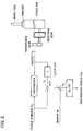
Figure 2 is a block diagram for explaining a sequence of finding a disturbance torque. -
Figure 3 is a flowchart illustrating a sequence of a state data recording process by an abnormality determination apparatus according to the first embodiment of the present invention. -
Figure 4 is a flowchart illustrating a sequence of an abnormality determination process by the abnormality determination apparatus according to the first embodiment of the present invention. -
Figure 5 is a view for explaining problems in an abnormality determination in conventional work equipment. -
Figure 6 is a view for explaining problems in an abnormality determination in the conventional work equipment. -
Figure 7 is a block diagram illustrating an overall configuration of an abnormality determination system according to a second embodiment of the present invention. - Hereunder, the first embodiment according to the present invention will be explained with reference to the drawings. In the description of the drawings, the same parts are represented with the same reference marks to omit explanation.
-
Figure 1 is a block diagram illustrating a configuration of an abnormality determination system provided with an abnormality determination apparatus according to the embodiment. As illustrated inFig. 1 , theabnormality determination system 100 according to the embodiment is configured with arobot 1, arobot control device 2, theabnormality determination apparatus 3, and aproduction management device 4. Therobot 1 is described as an example of work equipment provided with an attaching part to which a plural kinds of work parts are attached in a replaceable manner. For example, therobot 1 is a teaching-playback-type multiaxis machine and is of a multijoint type. However, therobot 1 may not be a multiaxis machine but may be a single axis machine. - Although the
robot 1 has a plurality of motor driving systems as joint axes or motion axes,Fig. 1 illustrates a motor driving system for one axis. Arobot arm 5 is driven through areduction gear 8 by a servomotor (hereunder simply mentioned as a motor) 6. Themotor 6 is provided with a pulse coder (a pulse generator or an encoder) 7 that is a detector for a rotation angle position and velocity. At a front end of therobot arm 5, there is arranged a changer C for attaching a tool T. The changer C functions as an attaching part to which a plural kinds of tools T are attached in a replaceable manner. The tool T is a work part that is attached to the front end of therobot arm 5 and performs an actual work. The tool T includes a welding work part such as a spot welder or a laser welder and a work object holding work part such as a work hand. Other then them, it may include a seal applying machine or the like. - The
robot control device 2 is provided with an integratedmotion control unit 9, acommunication unit 10, aservo control unit 11, and aservo amplification unit 14. Theservo control unit 11 includes a disturbancetorque calculation unit 12 and a statedata acquisition unit 13, and on receiving a command from the higher integratedmotion control unit 9, drives themotor 6 through theservo amplification unit 14. Thepulse coder 7 attached to themotor 6 forms, between theservo control unit 11, a feedback loop for controlling and processing the rotation angle position and velocity of themotor 6. - The
servo control unit 11 is provided with, other than the disturbancetorque calculation unit 12 and statedata acquisition unit 13, a processor for carrying out a process for controlling the rotation angle position, velocity, and current of themotor 6, a ROM for storing a control program, and a nonvolatile memory unit for storing set values and various kinds of parameters. Also, theservo control unit 11 is provided with a RAM for temporarily storing data during an operation process, a register for counting position feedback pulses from thepulse coder 7 and detecting an absolute rotation angle position of themotor 6, and the like. - The
robot 1 is of multijoint, and therefore, requires motor driving systems such as the one illustrated inFig. 1 to the number of joint axes. However, illustrated inFig. 1 is only for one axis and the other motor driving systems are omitted from the illustration. Further, there will be a case of interposing a speed changing gear train between themotor 6 and thereduction gear 8 ofFig. 1 . - The integrated
motion control unit 9 is positioned higher than theservo control unit 11 and achieves a direct operation control of therobot 1. Thecommunication unit 10 achieves, between acommunication unit 15 to be explained later of theabnormality determination apparatus 3, transmission and reception of necessary data via, for example, a LAN or the like. Also, the statedata acquisition unit 13 has a function of periodically collecting various kinds of data indicating operating states of the individual joint axes of therobot 1. The collected data include data indicating a collection period. The disturbancetorque calculation unit 12 has a function of calculating a disturbance torque value according to data acquired by the statedata acquisition unit 13. Since theservo control unit 11 is configured to include the disturbancetorque calculation unit 12 and statedata acquisition unit 13, a disturbance torque value obtained by calculation by the disturbancetorque calculation unit 12 is outputted through thecommunication unit 10 to theabnormality determination apparatus 3. With this configuration, theservo control unit 11 takes a so-called software servo aspect. - The
abnormality determination apparatus 3 is provided with thecommunication unit 15, adata acquisition unit 16, a workpart identification unit 17, an abnormality determinationdata setting unit 18, anabnormality determination unit 19, adatabase 20, and amaintenance record database 21. Here, theabnormality determination apparatus 3 has a controller made with a general-purpose electronic circuit such as a microcomputer, a microprocessor, a CPU, or the like and a peripheral device such as a memory. Accordingly, by executing a specific program, this controller operates as thecommunication unit 15,data acquisition unit 16, workpart identification unit 17, abnormality determinationdata setting unit 18,abnormality determination unit 19,database 20, andmaintenance record database 21. - The
communication unit 15 has a function of conducting transmission and reception of necessary data via, for example, a LAN or the like between therespective communication units robot control device 2 andproduction management device 4. - The
data acquisition unit 16 acquires state data from therobot 1 through thecommunication unit 15. In particular, thedata acquisition unit 16 acquires, as the state data, various kinds of data collected by the statedata acquisition unit 13 of therobot control device 2 and indicating operating states of therobot 1, as well as the disturbance torque value calculated by the disturbancetorque calculation unit 12. Then, thedata acquisition unit 16 records the acquired state data in thedatabase 20 according to the kind of the tool T identified by the workpart identification unit 17. - The work
part identification unit 17 identifies the kind of the tool T attached to the changer C. More precisely, the workpart identification unit 17 acquires, from themaintenance record database 21, a maintenance record recorded at the time when the tool T was attached, and according to the acquired maintenance record, identifies the kind of the tool T attached to the changer C. For example, if a date and time when the tool T was changed from T1 to T2 is recorded in the maintenance record, it is identified that the kind of the tool T is T1 before the date and time and that the kind of the tool T is T2 after the date and time. - The abnormality determination
data setting unit 18 sets, based on the kind of the tool T identified by the workpart identification unit 17, abnormality determination data for determining an abnormality of therobot 1. In particular, the abnormality determinationdata setting unit 18 calculates a threshold value from state data of the tool T of the identified kind identified by the workpart identification unit 17 and sets the calculated threshold value as abnormality determination data. For example, if the kind of the tool T is T1, the abnormality determinationdata setting unit 18 acquires state data of the tool T1 from thedatabase 20, uses the state data to calculate the average, variance, median of the same month previous year of the tool T1, and sets any one of them as a threshold value. - Also, the abnormality determination
data setting unit 18 may set the abnormality determination data by processing, with a predetermined learning model, the state data of the tool T whose kind was identified by the workpart identification unit 17. For example, if the kind of the tool T is T1, the abnormality determinationdata setting unit 18 acquires state data of the tool T1 from thedatabase 20, processes the same with a predetermined learning model to find a waveform pattern or probability distribution of disturbance torque values or the like, and sets the found one as the abnormality determination data. Also, other than this, it is possible to find a parameter such as a frequency or standard deviation indicating a disturbance torque value variation and set the found one as the abnormality determination data. - The
abnormality determination unit 19 acquires, from among the state data acquired by thedata acquisition unit 16, state data of the time when the tool T whose kind was identified by the workpart identification unit 17 was being attached. Then, the acquired state data is compared with the abnormality determination data set by the abnormality determinationdata setting unit 18 and an abnormality of therobot 1 is determined. - For example, if a threshold value serving as the abnormality determination data is set and if the kind of the tool T is T1, the
abnormality determination unit 19 acquires, from thedatabase 20, state data of the time when the tool T1 was being attached and uses the state data to calculate the latest average, variance, and median of the tool T1. Then, the average, variance, or median of the same month previous year set as the threshold value by the abnormality determinationdata setting unit 18 is compared with the calculated latest average, variance, or median and an abnormality of therobot 1 is determined. - Also, if a waveform pattern is set as the abnormality determination data, the
abnormality determination unit 19 acquires, from thedatabase 20, the state data of the time when the tool T1 was being attached and uses the state data to find a latest waveform pattern of the tool T1. Then, the waveform pattern of the same month previous year set by the abnormality determinationdata setting unit 18 is compared with the found latest waveform pattern and an abnormality of therobot 1 is determined. - The
database 20 functions as a memory unit to store state data acquired by thedata acquisition unit 16. Thedatabase 20 successively stores the state data according to the kind of the tool T and accumulates past state data. - As a technique of storing state data by the kinds of tools T, memory areas may be beforehand set according to the respective kinds of tools T and the state data of a tool T may be stored in a corresponding one of the memory areas. Alternatively, identification information such as a label showing the kind of a tool T may be added to state data thereof to be stored.
- The
maintenance record database 21 has a function of storing a maintenance record and an inspection result when maintenance and inspection are carried out on therobot 1. Accordingly, themaintenance record database 21 accumulates past maintenance record data and inspection result data. In particular, a maintenance record is recorded when a tool T is attached or replaced and includes the kinds of tools T before and after replacement and a replacement date and time. - The
production management device 4 is a device for conducting management of production information including, for example, working conditions of production lines in a factory and is provided with acommunication unit 22 and aproduction information database 23. Thecommunication unit 22 carries out transmission and reception of necessary data via, for example, a LAN or the like between thecommunication unit 15 of theabnormality determination apparatus 3. Theproduction information database 23 has a function of storing various kinds of collected production information. Accordingly, theproduction information database 23 accumulates various kinds of past production information. The production information includes the emergency stop information, maintenance record information, and the like of therobot 1 and of related facilities. - The embodiment detects, as an example of the state data, a disturbance torque (disturbance load torque) applied to the
motor 6 for driving each joint axis of therobot 1, and according to the disturbance torque, determines an abnormality of a corresponding motor driving system as an abnormality of therobot 1. A sequence of finding the disturbance torque is roughly as mentioned below. - As illustrated in the block diagram of
Fig. 2 , an actual velocity Vr of themotor 6 obtained from a velocity feedback signal from thepulse coder 7 is differentiated to find an acceleration α, and the acceleration α is multiplied by a total inertia J applied to themotor 6 to find an acceleration torque Ta (= J x α). Next, the found acceleration torque Ta is subtracted from a torque command Tc to themotor 6, and further, a moment M is subtracted therefrom to find a disturbance torque Tb. The torque command Tc is obtained from a velocity loop process of theservo control unit 11. Thereafter, a predetermined filtering process is carried out to remove disturbance irregular components to obtain a disturbance torque TG. Such a process is carried out by theservo control unit 11 every predetermined sampling period, to find the disturbance torque TG. - More precisely, the
servo control unit 11 is provided with a register that counts positional feedback pulses from thepulse coder 7 every predetermined sampling period and finds an absolute position of themotor 6. With this, theservo control unit 11 detects the absolute position of themotor 6 from the register, and from the absolute position of themotor 6, finds a rotation angle position (moved position) of the joint axis driven by themotor 6. Further, theservo control unit 11 carries out the process ofFig. 2 as explained before, to find the disturbance torque TG. - With reference to
Fig. 3 , a state data recording process by theabnormality determination apparatus 3 according to the embodiment will be explained.Figure 3 is a flowchart illustrating a processing sequence of the state data recording process by theabnormality determination apparatus 3. InFig. 3 , the disturbance torque value is explained as an example of the state data. - As illustrated in
Fig. 3 , in step S1, thedata acquisition unit 16 acquires disturbance torque values calculated by therobot control device 2. The disturbance torque values are values at respective moved positions of the respective motion axes. Also, at the same time, information indicating a period during which the disturbance torque values were collected is obtained. - In step S2, the
data acquisition unit 16 acquires facility emergency stop information from theproduction information database 23 of theproduction management device 4. In step S3, thedata acquisition unit 16 determines whether or not a facility emergency stop occurred during the collection period of the acquired disturbance torque values, and if determines that an emergency stop occurred, advances to step S4. On the other hand, if determines that no emergency stop occurred, it advances to step S5. - In step S4, the
data acquisition unit 16 deletes, from the acquired disturbance torque values, only a disturbance torque value of the time when the emergency stop occurred and advances to step S5. - In step S5, the work
part identification unit 17 refers to maintenance record data recorded in themaintenance record database 21 and identifies the kind of the tool T attached to the changer C of therobot 1. In the maintenance record, there are recorded a date and time when the tool T was replaced and the kinds of tools T before and after the replacement. Also, thedata acquisition unit 16 has acquired, at the time of acquisition of the disturbance torque values, the information indicating the period during which the disturbance torque values have been collected. Accordingly, based on the information, the workpart identification unit 17 identifies the kind of the tool T attached to the changer C at the time when the disturbance torque values were collected. - In step S6, the
data acquisition unit 16 records, in thedatabase 20 according to the kind of the tool T identified in step S5, disturbance torque values among the acquired disturbance torque values from which the abnormal value due to the facility emergency stop was deleted. Accordingly, thedatabase 20 records and accumulates only disturbance torque values excluding abnormal values caused by facility emergency stops associated with the kinds of tools T. - As a technique of recording state data according to the kinds of tools T, memory areas of the
database 20 may be beforehand set for the kinds of tools T, respectively, and thedata acquisition unit 16 may record disturbance torque values in a corresponding one of the set memory areas associated with the kind of the tool T. Alternatively, thedata acquisition unit 16 may add, to a disturbance torque value, identification information such as a label corresponding to the kind of the tool T identified in step S5, and then, may record the same in thedatabase 20. In this way, the acquired disturbance torque values are recorded in thedatabase 20, and then, the state data recording process according to the embodiment ends. - With reference to
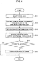
Fig. 4 , an abnormality determination process by theabnormality determination apparatus 3 according to the embodiment will be explained.Figure 4 is a flowchart illustrating a processing sequence of the abnormality determination process by theabnormality determination apparatus 3. InFig. 4 , the disturbance torque value is explained as an example of the state data. - As illustrated in
Fig. 4 , in step S11, the workpart identification unit 17 refers to maintenance record data recorded in themaintenance record database 21 and identifies the kind of the tool T attached to the changer C of therobot 1. The maintenance record records a date and time when the tool T was replaced and the kinds of tools T before and after the replacement, and therefore, the workpart identification unit 17 is able to identify the kind of the tool T attached to the changer C of therobot 1 by referring to the maintenance record. - In step S12, the abnormality determination
data setting unit 18 acquires from thedatabase 20 disturbance torque value data of the same month previous year of the day on which the diagnosis is carried out from among disturbance torque value data of the tool T whose kind was identified in step S11. - There are stored state data by the kinds of tools T in the
database 20, and therefore, the abnormality determinationdata setting unit 18 accesses a memory area in which disturbance torque values of the tool T of the identified kind identified in step S11 are stored and acquires the disturbance torque value data. Also, if identification information such as a label is added to state data of each kind of the tool T, the abnormality determinationdata setting unit 18 acquires, according to the identification information, the disturbance torque value data of the tool T whose kind was identified in step S11. However, if it is unable to acquire the disturbance torque value data of the same month previous year, nearest disturbance torque value data is deemed as the disturbance torque value data of the same month previous year and is acquired. - In step S13, the abnormality determination
data setting unit 18 sets, corresponding to the kind of the tool T identified in step S11, abnormality determination data for determining an abnormality of therobot 1. - For example, if the identified kind of the tool T is T1, the abnormality determination
data setting unit 18 acquires from thedatabase 20, from among state data of the time when the tool T1 was being attached, disturbance torque value data of the same month previous year of the day on which the diagnosis is carried out and calculates an average, a variance, and a median of the acquired data. Thereafter, one or a plurality of them is set as abnormality determination data to be used as a threshold value for determining an abnormality. In this way, the abnormality determinationdata setting unit 18 sets the abnormality determination data by using the state data of the time when the tool T1 was being attached, and therefore, the abnormality determination data is set associated with the kind of the tool T. - Also, the abnormality determination
data setting unit 18 may process, with a predetermined learning model, the disturbance torque value data of the same month previous year of the day on which the diagnosis is carried out and may thereby set the abnormality determination data. For example, with respect to the disturbance torque value data, a predetermined process may be carried out to find a waveform pattern or probability distribution of the disturbance torque values and the found one may be set as the abnormality determination data. Also, other than this, a parameter such as a frequency, a standard deviation, or the like indicating a disturbance torque value variation may be obtained and used as the abnormality determination data. - In step S14, the
abnormality determination unit 19 acquires from thedatabase 20, from among disturbance torque value data of the time when the tool T of the identified kind identified in step S11 was being attached, latest disturbance torque value data. Thereafter, in step S15, theabnormality determination unit 19 comperes the acquired latest disturbance torque value data with the abnormality determination data set in step S13 and determines whether or not therobot 1 is abnormal. - For example, if the identified kind of the tool T is T1, the
abnormality determination unit 19 acquires latest disturbance torque value data from among state data of the time when the tool T1 was being attached stored in thedatabase 20. Then, it calculates at least one (or a plurality is allowed) of the average, variance, and median of the acquired data. Thereafter, it determines whether or not the calculated average, variance, or median of the latest disturbance torque value data is equal to or smaller than the threshold value (e.g. the average, variance, or median of the same month previous year) set in step S13. As a result, if the average, variance, or median of the latest disturbance torque values is equal to or smaller than the threshold value, it is determined that no abnormality is occurring on therobot 1 and the abnormality determination process according to the embodiment ends. On the other hand, if the average, variance, or median of the latest disturbance torque values is greater than the threshold value (e.g. the average, variance, or median of the same month previous year), it is determined that there is a probability of an abnormality occurring on therobot 1 and it advances to step S16. - If a waveform pattern obtained from a learning model is set as the abnormality determination data, the
abnormality determination unit 19 acquires from thedatabase 20, from among the state data of the time when the tool T1 was being attached, the latest disturbance torque value data. Then, it carries out a predetermined process on the acquired data, finds a waveform pattern of the latest disturbance torque values, and carries out a matching of the found waveform pattern of the latest disturbance torque values with the waveform pattern set in step S13. As a result, if a matching level is equal to or greater than a predetermined value so that the waveform patterns agree with each other, it is determined that no abnormality is occurring on therobot 1 and the abnormality determination process according to the embodiment ends. On the other hand, if the matching level is smaller than the predetermined value so that the waveform patterns do not agree with each other, it is determined that there is a probability of an abnormality occurring on therobot 1 and it advances to step S16. - In step S16, the
abnormality determination unit 19 displays an abnormality alarm for the joint axis concerned on a display screen of a monitor (not illustrated) arranged for theabnormality determination apparatus 3 and the abnormality determination process according to the embodiment ends. - As explained above in detail, the
abnormality determination apparatus 3 according to the embodiment acquires state data from therobot 1 and identifies the kind of a tool T attached to the attaching part. Thereafter, corresponding to the tool T of the identified kind, it sets abnormality determination data for determining an abnormality of therobot 1, compares the set abnormality determination data with state data of the tool T of the identified kind, and determines an abnormality of therobot 1. With this, it is possible to correctly determine an abnormality of therobot 1 even if the tool T attached to a front end of the robot arm is replaced. - For example, as illustrated in
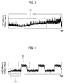
Fig. 5 , if a tool T1 is unchanged, i.e., not replaced, disturbance torque values are within a certain magnitude range, and therefore, setting a threshold value according to past responses enables an abnormality determination. - However, as illustrated in
Fig. 6 , even if it is the same robot, if the tool attached to the front end of the robot arm is replaced from T1 to T2, the weights and work motions of the tools greatly change to considerably shift a varying range of disturbance torque values. Due to this, setting the threshold value simply according to past responses is unable to correctly determine an abnormality of therobot 1. - For this, the
abnormality determination apparatus 3 according to the embodiment sets, corresponding to the kind of a tool T, abnormality determination data for determining an abnormality of therobot 1, compares the set abnormality determination data with state data of the tool T, and determines an abnormality of therobot 1. With this, it is possible to correctly determine an abnormality of therobot 1 even if the tool T attached to the front end of the robot arm is replaced. - Also, the
abnormality determination apparatus 3 according to the embodiment identifies, from maintenance records recorded at the time when a tool T is attached, the kind of the tool T attached to the attaching part. With this, since a maintenance record is always recorded when maintenance is carried out, there will be no need of separately generating special information for identifying the tool T. Accordingly, the tool T is identifiable without arranging an additional structure or process for identifying the tool T. - Also, the
abnormality determination apparatus 3 according to the embodiment further includes the state-data-storingdatabase 20 and stores state data according to the identified kind of a tool T in thedatabase 20. With this, state data corresponding to the kind of a tool T is easily acquirable from thedatabase 20. - Also, the
abnormality determination apparatus 3 according to the embodiment calculates a threshold value from state data of the time when a kind-identified tool T was being attached and sets the calculated threshold value as abnormality determination data. Namely, the threshold value is set by using the state data of the kind-identified tool T, so that the abnormality determination data corresponding to the kind of the tool T can be set. Accordingly, it is possible to correctly determine an abnormality of therobot 1 even if the tool T attached to the front end of the robot arm is replaced. - Further, the
abnormality determination apparatus 3 according to the embodiment processes, with a predetermined learning model, state data obtained at the time when a tool T of an identified kind was being attached and thereby sets abnormality determination data. Namely, the abnormality determination data is set with the use of the state data of the tool T of the identified kind, so that the abnormality determination data corresponding to the kind of the tool T can be set. Accordingly, it is possible to correctly determine an abnormality of therobot 1 even if the tool T attached to the front end of the robot arm is replaced. - Also, according to the
abnormality determination apparatus 3 of the embodiment, a plural kinds of tools T include at least a welding tool and a work object holding tool. With this, even if a various kinds of tools are attached, it is possible to correctly determine an abnormality of therobot 1. - The second embodiment of the present invention will be explained with reference to the drawings. Here, the same configurations as those of the first embodiment are represented with the same numerals to omit detailed explanation.
-
Figure 7 is a block diagram illustrating a configuration of an abnormality determination system provided with an abnormality determination apparatus according to the embodiment. As illustrated inFig. 7 , theabnormality determination system 100 according to the embodiment differs from that of the first embodiment in that the changer C of therobot 1 is provided with a workpart detection unit 70. - The work
part detection unit 70 functions as a sensor to detect the kind of a tool T attached to the changer C of therobot 1. The workpart detection unit 70 detects the kind of the tool T based on a structure of the tool T attached to the changer C. For example, it detects the kind of the tool T from a mechanical connection such as the shape of an attachment forming the changer C. - Also, the work
part detection unit 70 may receive a signal transmitted to the tool T, to detect the kind of the tool T according to an electric connection. Further, a communication tag or the like may be set on the tool T, to make theunit 70 possible to communicate with the tool T and detect the kind of the tool T. - The work
part detection unit 70 generates, upon detecting the kind of the tool T, identification information such as a label indicating the kind of the tool T and transmits the same to the integratedmotion control unit 9. However, the identification information may not be generated by the workpart detection unit 70 but may be generated by any unit in therobot control device 2. The generated identification information is transmitted with state data to theabnormality determination apparatus 3 through thecommunication unit 10. - The
data acquisition unit 16 simultaneously acquires, via thecommunication unit 15, the identification information when acquiring the state data from therobot 1. Thereafter, thedata acquisition unit 16 records the acquired state data and identification information in thedatabase 20 according to the kind of the tool T. At this time, thedata acquisition unit 16 itself refers to the identification information and records the state data in thedatabase 20 according to the kind of the tool T. - The work
part identification unit 17 identifies the kind of the tool T attached to the changer C based on the identification information acquired from therobot 1. For example, since a label indicating the kind of the tool T is recorded as the identification information together with various state data in thedatabase 20, the workpart identification unit 17 refers to the label and identifies the kind of the tool T attached to the changer C at the time when the various state data were generated. Also, the workpart identification unit 17 may directly acquire the identification information from therobot 1 and identify the kind of the tool T. - A state data recording process by the
abnormality determination apparatus 3 according to the embodiment will be explained. The state data recording process according to the embodiment differs from that of the first embodiment in step S5 ofFig. 3 of identifying the kind of the tool T and is the same as that of the first embodiment in the other steps. According to the first embodiment, step S5 refers to maintenance records to identify the kind of the tool T. According to the embodiment, it refers to the identification information to identify the kind of the tool T. In this way, the state data recording process of the embodiment is executable by the same flowchart ofFig. 3 , and therefore, detailed explanation is omitted. - An abnormality determination process by the
abnormality determination apparatus 3 according to the embodiment will be explained. The abnormality determination process according to the embodiment differs from that of the first embodiment in step S11 ofFig. 4 of identifying the kind of the tool T and is the same as that of the first embodiment in the other steps. According to the first embodiment, step S11 refers to maintenance records to identify the kind of the tool T. On the other hand, the embodiment refers to the identification information to identify the kind of the tool T. In this way, the abnormality determination process of the embodiment is executable by the same flowchart ofFig. 4 , and therefore, detailed explanation is omitted. - As explained above in detail, the
abnormality determination apparatus 3 according to the embodiment acquires identification information indicating the kind of a tool T from therobot 1, and according to the identification information, identifies the kind of the tool T attached to the changer C. With this, it is possible to easily identify the kind of the tool T only by referring to the identification information. - Also, the
abnormality determination apparatus 3 according to the embodiment is further provided with the workpart detection unit 70 to detect the kind of a tool T attached to the changer C of therobot 1. With this, it is possible to directly detect the kind of the tool T attached to the changer C, thereby easily detecting the kind of the tool T. - Further, the
abnormality determination apparatus 3 according to the embodiment detects the kind of the tool T according to a structure of a tool T attached to the changer C. Accordingly, it is possible to easily detect the kind of the tool T from the shape or the like of an attachment that forms the changer C and eliminate detection errors. - The
abnormality determination apparatus 3 according to the embodiment communicates with a tool T attached to the changer C and detects the kind of the tool T. With this, it is possible to detect the kind of the tool T even among tools having the same mechanical connection or attachment shape. - The above-mentioned embodiments are examples of the present invention. The present invention, therefore, is not limited to the above-mentioned embodiments and naturally allows, without departing from the technical ideas of the present invention, other embodiments and various modifications depending on designing and the like.
-
- 1:
- Robot
- 2:
- Robot control device
- 3:
- Abnormality determination apparatus
- 4:
- Production management device
- 5:
- Robot arm
- 6:
- Servomotor
- 7:
- Pulse coder
- 8:
- Reduction gear
- 9:
- Integrated motion control unit
- 10, 15, 22:
- Communication unit
- 11:
- Servo control unit
- 12:
- Disturbance torque calculation unit
- 13:
- State data acquisition unit
- 14:
- Servo amplification unit
- 16:
- Data acquisition unit
- 17:
- Work part identification unit
- 18:
- Abnormality determination data setting unit
- 19:
- Abnormality determination unit
- 20:
- Database
- 21:
- Maintenance record database
- 23:
- Production information database
- 70:
- Work part detection unit
- 100:
- Abnormality determination system
- C:
- Changer
- T:
- Tool
Claims (12)
- An abnormality determination apparatus comprising a controller that acquires state data indicating a state of work equipment from the work equipment provided with an attaching part to which a plural kinds of work parts are attached in a replaceable manner and determines an abnormality of the work equipment, characterized in that the controller:acquires the state data from the work equipment;identifies the kind of a work part attached to the attaching part;sets abnormality determination data for determining an abnormality of the work equipment corresponding to the identified kind of the work part; andacquires state data of a time when the identified kind of the work part was being attached from among state data acquired from the work equipment andcompares the acquired state data with the set abnormality determination data so that determines an abnormality of the work equipment.
- The abnormality determination apparatus as set forth in claim 1, characterized in that
the controller identifies the kind of the work part attached to the attaching part according to a maintenance record recorded when the work part was attached. - The abnormality determination apparatus as set forth in claim 1, characterized in that
the controller acquires identification information indicating the kind of the work part from the work equipment, and identifies the kind of the work part attached to the attaching part according to the identification information. - The abnormality determination apparatus as set forth in any one of claims 1 to 3further comprising a memory for storing the state data, whereinthe controller records the state data in the memory according to the identified kind of the work part.
- The abnormality determination apparatus as set forth in any one of claims 1 to 4, characterized in thatthe controller calculates a threshold value from the state data of the time when the identified kind of the work part was being attached andsets the calculated threshold value as the abnormality determination data.
- The abnormality determination apparatus as set forth in any one of claims 1 to 4, characterized in that
the controller processes the state data of the time when the identified kind of the work part was being attached with use of a predetermined learning model to set the abnormality determination data. - The abnormality determination apparatus as set forth in any one of claims 1 to 6, characterized in that
the plural kinds of work parts include at least a work part for welding and a work part for holding a work object. - An abnormality determination system comprising:work equipment provided with an attaching part to which a plural kinds of work parts are attached in a replaceable manner; andan abnormality determination apparatus for acquiring state data indicating a state of the work equipment from the work equipment and determining an abnormality of the work equipment, characterized in that the abnormality determination apparatus:acquires the state data from the work equipment;identifies the kind of the work part attached to the attaching part;sets abnormality determination data for determining an abnormality of the work equipment corresponding to the identified kind of the work part; andacquires state data of a time when the identified kind of the work part was being attached from among state data acquired from the work equipment and compares the acquired state data with the set abnormality determination data so that determines an abnormality of the work equipment.
- The abnormality determination system as set forth in claim 8, further comprising a sensor for detecting the kind of the work part attached to the attaching part of the work equipment.
- The abnormality determination system as set forth in claim 9, characterized in that the sensor detects the kind of the work part according to a structure of the work part attached to the attaching part.
- The abnormality determination system as set forth in claim 9, characterized in that the sensor communicates with the work part attached to the attaching part so that detect the kind of the work part.
- An abnormality determination method of an abnormality determination apparatus for acquiring state data indicating a state of work equipment from the work equipment provided with an attaching part to which a plural kinds of work parts are attached in a replaceable manner and determining an abnormality of the work equipment, comprising:acquiring the state data from the work equipment;identifying the kind of a work part attached to the attaching part;setting abnormality determination data for determining an abnormality of the work equipment corresponding to the identified kind of the work part; andacquiring state data of a time when the identified kind of the work part was being attached from among state data acquired from the work equipment and comparing the acquired state data with the set abnormality determination data to determine an abnormality of the work equipment.
Applications Claiming Priority (1)
| Application Number | Priority Date | Filing Date | Title |
|---|---|---|---|
| PCT/JP2018/017419 WO2019211892A1 (en) | 2018-05-01 | 2018-05-01 | Malfunction determination device, malfunction determination system, and malfunction determination method |
Publications (2)
| Publication Number | Publication Date |
|---|---|
| EP3789165A1 true EP3789165A1 (en) | 2021-03-10 |
| EP3789165A4 EP3789165A4 (en) | 2021-08-18 |
Family
ID=68386472
Family Applications (1)
| Application Number | Title | Priority Date | Filing Date |
|---|---|---|---|
| EP18917410.5A Withdrawn EP3789165A4 (en) | 2018-05-01 | 2018-05-01 | DEVICE, SYSTEM AND METHOD FOR DETERMINING MALFUNCTIONING |
Country Status (5)
| Country | Link |
|---|---|
| US (1) | US11931904B2 (en) |
| EP (1) | EP3789165A4 (en) |
| JP (1) | JP6927421B2 (en) |
| CN (1) | CN112135720A (en) |
| WO (1) | WO2019211892A1 (en) |
Families Citing this family (5)
| Publication number | Priority date | Publication date | Assignee | Title |
|---|---|---|---|---|
| JP7248877B2 (en) * | 2018-12-21 | 2023-03-30 | 日立建機株式会社 | Selection system for maintenance parts for working machines |
| US20230288905A1 (en) * | 2020-10-22 | 2023-09-14 | Riho Kubota | Control device, machine tool system, and control method |
| US20240177461A1 (en) * | 2021-06-23 | 2024-05-30 | Fanuc Corporation | Teaching device |
| JP2023125498A (en) * | 2022-02-28 | 2023-09-07 | オムロン株式会社 | Screw tightening system, controller, and control program |
| DE102024125028A1 (en) * | 2024-09-02 | 2026-03-05 | P&L Gmbh & Co. Kg | METHOD FOR DETECTING WEAR ON A TOOL |
Family Cites Families (23)
| Publication number | Priority date | Publication date | Assignee | Title |
|---|---|---|---|---|
| JPS63288688A (en) * | 1987-05-18 | 1988-11-25 | 本田技研工業株式会社 | Robot hand identification device |
| US6260427B1 (en) * | 1997-07-28 | 2001-07-17 | Tri-Way Machine Ltd. | Diagnostic rule tool condition monitoring system |
| JPH11333657A (en) | 1998-05-22 | 1999-12-07 | Okuma Corp | Abnormality monitoring device for tool change operation |
| JP2001147707A (en) * | 1999-11-24 | 2001-05-29 | Olympus Optical Co Ltd | Working result recorder |
| JP2004017260A (en) | 2002-06-20 | 2004-01-22 | Kawasaki Heavy Ind Ltd | Automatic assembly work device with separation function for end effector |
| JP2007219991A (en) * | 2006-02-20 | 2007-08-30 | Fanuc Ltd | Abnormal load detection device |
| JP4301278B2 (en) * | 2006-09-29 | 2009-07-22 | パナソニック電工株式会社 | Machine tool machining dimension prediction device |
| US7421886B1 (en) * | 2007-06-15 | 2008-09-09 | Fox Michael A | Quick connect coupling test apparatus and method |
| US8316742B2 (en) | 2007-12-11 | 2012-11-27 | Kennametal Inc. | Cutting tool with integrated circuit chip |
| JP5589460B2 (en) * | 2010-03-15 | 2014-09-17 | 豊和工業株式会社 | Tool holder mounting abnormality detection method and machine tool |
| JP5914994B2 (en) * | 2011-06-06 | 2016-05-11 | セイコーエプソン株式会社 | Robot and robot control method |
| JP5846479B2 (en) | 2011-08-23 | 2016-01-20 | 株式会社Ihi | Robot and its control method |
| JP2014018822A (en) * | 2012-07-17 | 2014-02-03 | Amada Co Ltd | Tool exchange method, and device |
| CN109213123A (en) * | 2012-07-26 | 2019-01-15 | 苏州宝时得电动工具有限公司 | The control method and robot system of robot |
| JP5942720B2 (en) * | 2012-09-12 | 2016-06-29 | セイコーエプソン株式会社 | State determination method, robot, control device, and program |
| JP5962371B2 (en) * | 2012-09-20 | 2016-08-03 | 株式会社Ihi | Robot system and sensor inspection apparatus and method |
| JP2016087700A (en) | 2014-10-29 | 2016-05-23 | ファナック株式会社 | Control equipment having feature of verifying designation of load information |
| JP6492677B2 (en) * | 2015-01-15 | 2019-04-03 | 株式会社デンソー | In-vehicle machine |
| JP6430263B2 (en) * | 2015-01-19 | 2018-11-28 | 株式会社日立製作所 | Abnormality diagnosis analyzer |
| EP3299133B1 (en) * | 2015-05-22 | 2020-09-02 | Nissan Motor Co., Ltd. | Failure diagnosis device and failure diagnosis method |
| EP3305482B1 (en) * | 2015-05-25 | 2019-10-09 | Nissan Motor Co., Ltd. | Failure diagnosis device and failure diagnosis method |
| JP2017033346A (en) | 2015-08-03 | 2017-02-09 | オークマ株式会社 | Information acquisition device for machine tools |
| JP6542713B2 (en) | 2016-06-09 | 2019-07-10 | ファナック株式会社 | Machine learning device, numerical controller and machine learning method for learning an abnormal load detection threshold |
-
2018
- 2018-05-01 JP JP2020516985A patent/JP6927421B2/en active Active
- 2018-05-01 CN CN201880093027.6A patent/CN112135720A/en active Pending
- 2018-05-01 EP EP18917410.5A patent/EP3789165A4/en not_active Withdrawn
- 2018-05-01 US US17/051,950 patent/US11931904B2/en active Active
- 2018-05-01 WO PCT/JP2018/017419 patent/WO2019211892A1/en not_active Ceased
Also Published As
| Publication number | Publication date |
|---|---|
| JP6927421B2 (en) | 2021-08-25 |
| CN112135720A (en) | 2020-12-25 |
| EP3789165A4 (en) | 2021-08-18 |
| WO2019211892A1 (en) | 2019-11-07 |
| US11931904B2 (en) | 2024-03-19 |
| US20210229283A1 (en) | 2021-07-29 |
| JPWO2019211892A1 (en) | 2021-05-13 |
Similar Documents
| Publication | Publication Date | Title |
|---|---|---|
| US11931904B2 (en) | Abnormality determination apparatus, abnormality determination system, and abnormality determination method | |
| RU2678857C1 (en) | Troubleshooting diagnostics device and way of diagnosing the problems | |
| CN107614217B (en) | Fault diagnosis device and fault diagnosis method | |
| RU2683151C1 (en) | Faults diagnostics device and the faults diagnosing method | |
| CN107614214B (en) | Trouble-shooter and method for diagnosing faults | |
| EP2333623A1 (en) | Monitoring system for data acquisition in a production environment | |
| CN107614213B (en) | Fault diagnosis device and fault diagnosis method |
Legal Events
| Date | Code | Title | Description |
|---|---|---|---|
| STAA | Information on the status of an ep patent application or granted ep patent |
Free format text: STATUS: THE INTERNATIONAL PUBLICATION HAS BEEN MADE |
|
| PUAI | Public reference made under article 153(3) epc to a published international application that has entered the european phase |
Free format text: ORIGINAL CODE: 0009012 |
|
| STAA | Information on the status of an ep patent application or granted ep patent |
Free format text: STATUS: REQUEST FOR EXAMINATION WAS MADE |
|
| 17P | Request for examination filed |
Effective date: 20201127 |
|
| AK | Designated contracting states |
Kind code of ref document: A1 Designated state(s): AL AT BE BG CH CY CZ DE DK EE ES FI FR GB GR HR HU IE IS IT LI LT LU LV MC MK MT NL NO PL PT RO RS SE SI SK SM TR |
|
| AX | Request for extension of the european patent |
Extension state: BA ME |
|
| RIC1 | Information provided on ipc code assigned before grant |
Ipc: B25J 19/06 20060101AFI20210406BHEP Ipc: G05B 19/4065 20060101ALI20210406BHEP Ipc: B23Q 11/00 20060101ALI20210406BHEP Ipc: B23Q 17/09 20060101ALI20210406BHEP Ipc: B23Q 17/12 20060101ALI20210406BHEP Ipc: G05B 19/418 20060101ALI20210406BHEP Ipc: G05B 23/02 20060101ALI20210406BHEP Ipc: B23Q 3/16 20060101ALN20210406BHEP Ipc: B25J 15/04 20060101ALN20210406BHEP |
|
| DAV | Request for validation of the european patent (deleted) | ||
| DAX | Request for extension of the european patent (deleted) | ||
| A4 | Supplementary search report drawn up and despatched |
Effective date: 20210715 |
|
| RIC1 | Information provided on ipc code assigned before grant |
Ipc: B25J 19/06 20060101AFI20210709BHEP Ipc: G05B 19/4065 20060101ALI20210709BHEP Ipc: B23Q 11/00 20060101ALI20210709BHEP Ipc: B23Q 17/09 20060101ALI20210709BHEP Ipc: B23Q 17/12 20060101ALI20210709BHEP Ipc: G05B 19/418 20060101ALI20210709BHEP Ipc: G05B 23/02 20060101ALI20210709BHEP Ipc: B23Q 3/16 20060101ALN20210709BHEP Ipc: B25J 15/04 20060101ALN20210709BHEP |
|
| STAA | Information on the status of an ep patent application or granted ep patent |
Free format text: STATUS: EXAMINATION IS IN PROGRESS |
|
| 17Q | First examination report despatched |
Effective date: 20231113 |
|
| STAA | Information on the status of an ep patent application or granted ep patent |
Free format text: STATUS: THE APPLICATION IS DEEMED TO BE WITHDRAWN |
|
| 18D | Application deemed to be withdrawn |
Effective date: 20251202 |