EP3789101A1 - Air drying device and sieve element - Google Patents
Air drying device and sieve element Download PDFInfo
- Publication number
- EP3789101A1 EP3789101A1 EP19195979.0A EP19195979A EP3789101A1 EP 3789101 A1 EP3789101 A1 EP 3789101A1 EP 19195979 A EP19195979 A EP 19195979A EP 3789101 A1 EP3789101 A1 EP 3789101A1
- Authority
- EP
- European Patent Office
- Prior art keywords
- sieve element
- air
- treatment system
- sieve
- air treatment
- Prior art date
- Legal status (The legal status is an assumption and is not a legal conclusion. Google has not performed a legal analysis and makes no representation as to the accuracy of the status listed.)
- Pending
Links
- 238000007605 air drying Methods 0.000 title claims abstract description 11
- 238000001035 drying Methods 0.000 claims abstract description 7
- 230000007246 mechanism Effects 0.000 claims description 7
- 230000000295 complement effect Effects 0.000 claims description 4
- 238000007789 sealing Methods 0.000 description 21
- 239000003921 oil Substances 0.000 description 18
- 239000002274 desiccant Substances 0.000 description 17
- 230000008929 regeneration Effects 0.000 description 14
- 238000011069 regeneration method Methods 0.000 description 14
- 239000002184 metal Substances 0.000 description 9
- 239000002245 particle Substances 0.000 description 7
- OKTJSMMVPCPJKN-UHFFFAOYSA-N Carbon Chemical compound [C] OKTJSMMVPCPJKN-UHFFFAOYSA-N 0.000 description 5
- 229910052799 carbon Inorganic materials 0.000 description 5
- 238000000034 method Methods 0.000 description 4
- 239000008187 granular material Substances 0.000 description 3
- 239000000126 substance Substances 0.000 description 3
- 230000002411 adverse Effects 0.000 description 2
- 230000006835 compression Effects 0.000 description 2
- 238000007906 compression Methods 0.000 description 2
- 238000001914 filtration Methods 0.000 description 2
- 239000007788 liquid Substances 0.000 description 2
- 238000011045 prefiltration Methods 0.000 description 2
- 238000009423 ventilation Methods 0.000 description 2
- 238000013022 venting Methods 0.000 description 2
- 239000000853 adhesive Substances 0.000 description 1
- 230000001070 adhesive effect Effects 0.000 description 1
- 239000000443 aerosol Substances 0.000 description 1
- 230000000712 assembly Effects 0.000 description 1
- 238000000429 assembly Methods 0.000 description 1
- 238000011109 contamination Methods 0.000 description 1
- 230000000694 effects Effects 0.000 description 1
- 239000000839 emulsion Substances 0.000 description 1
- 230000008014 freezing Effects 0.000 description 1
- 238000007710 freezing Methods 0.000 description 1
- 229910000679 solder Inorganic materials 0.000 description 1
- 238000011144 upstream manufacturing Methods 0.000 description 1
- 238000003466 welding Methods 0.000 description 1
Images



Classifications
-
- B—PERFORMING OPERATIONS; TRANSPORTING
- B01—PHYSICAL OR CHEMICAL PROCESSES OR APPARATUS IN GENERAL
- B01D—SEPARATION
- B01D53/00—Separation of gases or vapours; Recovering vapours of volatile solvents from gases; Chemical or biological purification of waste gases, e.g. engine exhaust gases, smoke, fumes, flue gases, aerosols
- B01D53/26—Drying gases or vapours
- B01D53/261—Drying gases or vapours by adsorption
-
- B—PERFORMING OPERATIONS; TRANSPORTING
- B01—PHYSICAL OR CHEMICAL PROCESSES OR APPARATUS IN GENERAL
- B01D—SEPARATION
- B01D53/00—Separation of gases or vapours; Recovering vapours of volatile solvents from gases; Chemical or biological purification of waste gases, e.g. engine exhaust gases, smoke, fumes, flue gases, aerosols
- B01D53/02—Separation of gases or vapours; Recovering vapours of volatile solvents from gases; Chemical or biological purification of waste gases, e.g. engine exhaust gases, smoke, fumes, flue gases, aerosols by adsorption, e.g. preparative gas chromatography
- B01D53/04—Separation of gases or vapours; Recovering vapours of volatile solvents from gases; Chemical or biological purification of waste gases, e.g. engine exhaust gases, smoke, fumes, flue gases, aerosols by adsorption, e.g. preparative gas chromatography with stationary adsorbents
- B01D53/0407—Constructional details of adsorbing systems
- B01D53/0415—Beds in cartridges
-
- B—PERFORMING OPERATIONS; TRANSPORTING
- B01—PHYSICAL OR CHEMICAL PROCESSES OR APPARATUS IN GENERAL
- B01D—SEPARATION
- B01D2257/00—Components to be removed
- B01D2257/80—Water
-
- B—PERFORMING OPERATIONS; TRANSPORTING
- B01—PHYSICAL OR CHEMICAL PROCESSES OR APPARATUS IN GENERAL
- B01D—SEPARATION
- B01D2258/00—Sources of waste gases
- B01D2258/06—Polluted air
-
- B—PERFORMING OPERATIONS; TRANSPORTING
- B01—PHYSICAL OR CHEMICAL PROCESSES OR APPARATUS IN GENERAL
- B01D—SEPARATION
- B01D2259/00—Type of treatment
- B01D2259/45—Gas separation or purification devices adapted for specific applications
- B01D2259/4566—Gas separation or purification devices adapted for specific applications for use in transportation means
Definitions
- the invention relates to an air drying device for a compressed air treatment system of a vehicle, in particular a utility vehicle, with a housing and an air drying means contained in the housing.
- Air drying devices such as air dryer cartridges are used as wearing parts within compressed air supply or compressed air treatment systems especially in the commercial vehicle sector. There they are used to clean the generated compressed air from oil and dirt particles and to dry the compressed air.
- a conventional dryer cartridge 10 for a compressed air treatment system of a vehicle as shown Fig. 1 comprises a housing 16 and a base plate, which together in the assembled state of the air dryer cartridge define a volume of the air dryer cartridge.
- the cartridge comprises disposed within the volume as a part of an air drying means a desiccant 38 filled desiccant box 20 which is arranged in the housing 16.
- the base plate comprises an air inlet 50 and an air outlet 52.
- An O-ring 44 and a sealing ring 40 seal between the base plate and the desiccant box 20.
- the sealing ring 40 can comprise a rubber lip seal, with a rubber lip 48 acting as a non-return valve. In alternative devices the sealing ring 40 may consist of another O-ring.
- the sealing ring 40 is mechanically or chemically connected to the desiccant box 20, whereby the rubber lip 48 has a defined opening and closing characteristic.
- the rubber lip 48 opens when there is excess pressure in the air dryer cartridge 10 and thus acts as a safety valve.
- the desiccant box 20 is limited in its axial direction of extension by a first air filter 30.
- a second air filter 31 or a fleece can be provided which retain the desiccant 38 inside the desiccant box 20.
- An optional compression spring 34 and a granulate cover 36 can also be provided in the upper area or lower area of the air dryer cartridge 10 to compress the desiccant 38 inside the desiccant box 20.
- the granulate cover 36 is particularly air-permeable.
- a combination filter for example in the form of a coalescing filter 26, extends in the axial direction around the lower half of the desiccant box 20 and is fixed in the radial direction by a sleeve 28 to a supporting structure of the desiccant box 20.
- the coalescing filter 26 divides the air dryer cartridge 10 into a pre-filter area and an after-filter area.
- the task of the coalescing filter 26 during a compressed air conveying phase is to hold oil and dirt particles as well as emulsion droplets on an inflow surface, to store liquid oil and to convert the finest oil droplets and aerosols into liquid oil by a coalescing effect and to separate them.
- the design of the outflow surface and the filter design results in a defined ratio of air outflow velocity and oil droplet size. This ratio guarantees that no oil droplets enter the desiccant box 20 via the after-filter area and thus shorten the service life of the air dryer cartridge 10 and downstream consumers.
- Air guide elements 46 can be provided that project radially from the desiccant box 20 into the coalescing filter 26 and prevent the coalescing filter 26 from being bypassed by incoming air.
- the sealing during a compressed air conveying phase between the pre-filter area and the after-filter area is thus achieved by a special sealing geometry consisting of the air guide elements 46 in conjunction with the outer sleeve 28.
- a projection 72 is disposed on the support member 18.
- the projection 72 is surrounded by a first seal 68 which seals between the support member 18 and the cartridge housing and a second seal 73 which seals between the support member 18 and a housing of an air treatment system 14 as shown in figure 2 .
- This arrangement may, for example, be intended for mounting the air dryer cartridge 10 to the air treatment system 14 by means of a bayonet ring.
- the air dryer cartridge 10 can comprise means for a thread connection with the air treatment system 14.
- the projection 72 can be omitted and a thread symmetrically arranged with respect to the longitudinal axis of the air dryer cartridge 10 can be provided in the support member 18 which can be fitted to a corresponding thread of the air treatment system 14 to mount the air dryer cartridge 10 to the air treatment system 14.
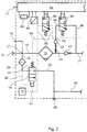
- FIG 2 shows a section of a schematic air treatment system 14 to which the air dryer cartridge 10 can be assembled.
- the air treatment system 14 has a compressed air inlet 12 to which a compressor can be connected.
- the air treatment system 14 includes an external filling connection 75 which can also be used to supply compressed air from an external compressed air source to the air treatment system 14, for example for service purposes in a workshop.
- a data bus connection 77 is provided via which the air treatment system 14 can communicate with other subsystems of the commercial vehicle, such as an engine control system.
- the air treatment system 14 comprises a compressed air delivery line 17, which connects the compressed air inlet 12 with the replaceable air dryer cartridge 10.
- the air dryer cartridge 10 cleans the conveyed compressed air of oil and dirt particles and removes moisture from it.
- Air processed by the air dryer cartridge 10 is passed downstream of the air dryer cartridge 10 via a check valve 47.
- a multi-circuit protection valve connection 71 is indicated, whereby the multi-circuit protection valve not shown can be a component separate from the compressed air treatment system 10 or integrated into the compressed air treatment system 10.
- processed compressed air bypassing the check valve 47 can regenerate the air dryer cartridge 10 by reversing the flow direction via a regeneration line 58, another check valve 49 and a throttle 51. In the process, oil and dirt particles collected in the air dryer cartridge 10 as well as moisture stored in the desiccant are rinsed out of the air dryer cartridge 10.
- the regeneration air continues to flow backwards through the compressed air delivery line 17 to a branching point 21 and from there via a vent line 22 to a vent 80.
- a drain valve 19 which can be designed as a 2/2-way valve, for example.
- a sieve element 24 which retains coarse dirt particles.
- the sieve element 24 which can comprise an oil carbon sieve protects the drain valve 19 against cracked oils, which damage or block the drain valve 19, which can lead to permanent leakages and air loss of the whole air treatment system 10. These cracked oils occur mainly, if a bad compressor is used, which burns oil due to too high operating temperature.
- the regeneration cycle can be controlled with a regeneration solenoid valve 56, which is arranged in the regeneration line 58 and can be designed as a 3/2-way valve, for example.
- a closing spring 93 of the drain valve 19 can be pre-tensioned via a control line 53, which branches off from the regeneration line 58 at a branch point 55, in order to adjust the pneumatic opening pressure of the drain valve 19, for example between an opening pressure of approx. 9.5 to 10 bar if the control line 53 is pressureless and an opening pressure of approx. 16 to 17 bar if the control line 53 is pressurized.
- the drain valve 19 can be pneumatically actuated via a further control line 60 in which a solenoid valve 62, designed as a 3/2-way valve for example, is arranged.
- both the regeneration solenoid valve 56 and the solenoid valve 62 can be actuated simultaneously, so that the regeneration air reaches the vent 80 via the sieve element 24 and the drain valve 19 in order to exit the system there.
- the further control line 60 can have a further branch point 91, via which a further valve device 74 can be controlled, which in turn can put an unrepresented compressor, which provides the compressed air at the compressed air inlet 12, into an energy-saving operating state.
- the valve device 74 can enable particularly fast venting of the other control line 60 in order to change the operating state of the compressor more quickly.
- a normally reduced compressed air flow rate of the compressor exits the system directly from the compressed air inlet via the sieve element 24 and the drain valve 19 via the vent 80.
- a reduced compressed airflow rate may be approximately 20 percent of the normally conveyed compressed air volume.
- vent 80 can be connected to other components of the air treatment system 14, which are not shown, via an additional ventilation line 59. These components can also use vent 80 to expel compressed air from the system. Furthermore, the venting indicated on the regeneration solenoid valve 56 and the solenoid valve 62 can also be coupled with the vent 80, whereby the explicit representation of corresponding connecting lines has been omitted for a better overview.
- the air treatment system 14 comprises a control unit 64, which can control the regeneration solenoid valve 56 and the solenoid valve 62 and can be coupled to other subsystems of the commercial vehicle via the data bus connection 77.
- a heater 69 and a pressure sensor 66 which is controlled by the control unit 64 or via which the control unit 64 receives information on the pressure levels prevailing in the air treatment system 14.
- Heater 69 can be used in particular to prevent pressure lines from freezing.
- the pressure sensor 66 is only to be understood as an example for a whole number of pressure sensors which can measure the pressure in the air treatment system 14 at various points.
- 22 pressure sensors can be arranged upstream and downstream of the sieve element 24 in the vent line to determine a back pressure drop on the sieve element 24 when the drain valve 19 is open. In this way, a blockage of the sieve element 24 can be detected which would hinder the escape of the compressed air during a regeneration cycle, whereby this blockage can be a change criterion.
- the drain valve 19 also serves as a safety valve to prevent a dangerous increase in pressure in the air treatment system 14.
- a control line 95 is provided for this purpose, which opens the drain valve when an adjustable safety pressure is exceeded.
- an oil carbon sieve as sieve element 24, which is intended as a separate piece and installed in the air treatment system 14.
- An example of an oil carbon sieve is described in European patent application EP 2505444 A2 .
- the air dryer cartridge 10 and the sieve element 24 have to be mounted to the air treatment system 14 and be replaced as separate pieces, which is cumbersome.
- the sieve moves away from its mounting position during operation of the vehicle in which the air treatment system 14 is mounted, for example, because of vibrations caused by the movement of the vehicle.
- the sieve element 24 can be located in the air treatment system 14 behind the air dryer cartridge 10 so that it is not visible during the assembling of the air dryer cartridge 10.
- a conventional sieve element 24 can be cumbersome, since it is usually oil-contaminated after use and furthermore can be relatively small so that it is difficult to grab.
- a device for drying air of an air treatment system of a vehicle also denoted as an air dryer cartridge, comprising a housing, an air drying means contained in the housing, an air inlet configured to receive air from the air treatment system and an air outlet for outputting air to the air treatment system, a connection means configured for mounting the device to the air treatment system, wherein the device is configured to be connected to a sieve element that can be arranged in an stream of air between the air treatment system and the device.
- the air dryer cartridge of the present invention has the advantage that it can be mounted together with the sieve element as one part to the air treatment system, so that the risk that the sieve displaces from its intended position in the air treatment system during or after the mounting of the device can be avoided even if the sieve element is hidden behind the device and not visible by an assembler during the mounting.
- mounting time of the air dryer cartridge device and the sieve element can be reduced since both parts are combined into one part and are mounted simultaneously as one piece.
- Providing the sieve element connected to the cartridge as one piece also has the advantage that both parts can be replaced together without the need to touch or grab the sieve element which is frequently contaminated with oil after its use.
- connection means is at least a part of one of a bayonet connector, a thread connection, a plug connection.
- connection means can be used for air dryer cartridge devices being designed for different types of mounting mechanisms including spin-on designs and thread less mounting designs.
- the device comprises at least one of a magnet, a thread, a part of a clip mechanism configured for connecting a sieve element to it.
- connection means provide for a reliable but detachable connection between the device and the sieve element.
- the device is configured or comprises a connection part for connecting the sieve element to the device so that the sieve element can be mounted to the device with the sieve element being rotatable about an axis of the device.
- This configuration permits to design the device with a spin-on connection means such as a thread for assembly to the air treatment system, wherein the sieve element can be introduced into a recess or seat connected to a vent line of the air treatment system, and remains circumferentially in rest, while the device is getting connected to the air treatment system by screwing it into a corresponding thread seat of the air treatment system.
- the sieve element which remains circumferentially in rest, together with the device being screwed into the thread seat of the air treatment system, is advanced into the recess or seat connected to the vent line of the air treatment system.
- the device is configured or comprises a connection part to connect a sieve element to the device so that the sieve element is mounted to the device in such a manner that the sieve element is movable along an axis, in particular, the longitudinal axis of the device about a predetermined distance.
- This configuration permits the sieve element to correctly adjust its position in the air treatment system and, in particular, permits to adjust its longitudinal position and extension, which ensures a tight seat in a recess in the air treatment system. Thus air can be prevented from bypassing the sieve element.
- the sieve element comprises one or more expandable lateral walls supporting a top wall of the sieve element which can be displaced with respect to a top side of the device so that the volume covered by the sieve element can be varied.
- One or more sieves can be provided in one or more of the top wall and the one or more expandable lateral walls of the sieve element.
- the device comprises a sealing means configured to seal the device against the air treatment system when the device is mounted to the air treatment system.
- the sealing means can be an O-ring or a lip provided in or connected to a base plate of the device.
- the sieve element connected to the device is positioned within a sealed volume between the air treatment system and the device sealed by the sealing means.
- the base plate of the device may comprise at least one of an air inlet and an air outlet connected to respective lines such as a vent line and/or an air delivery line of the air treatment system for exchange of an airstream between the device and the air treatment system through the sieve element.
- the device further comprises the sieve element integrally connected to the device.
- the sieve element may comprise one or more sieves.
- the device comprises the sieve element, wherein the sieve element comprises at least one of a magnet, a thread, a part of a clip mechanism configured for connecting the sieve element to a respective complementary part of the device.
- the sieve element or a part thereof comprises a symmetric, in particular rotation symmetric design, the shape of a circular arc or a ring shape, the sieve element or the part thereof being symmetric with respect to a longitudinal axis of the device.
- This configuration is suitable for a device having a spin on design, wherein the sieve element or a part thereof is configured so that it is movable with respect to the device when it is connected to it so that the sieve element remains in a circumferentially fixed position with respect to the air treatment system, when the device is screwed into a thread or seat of the air treatment system.
- the sieve element comprises a shape of a box comprising at least two sieves arranged in two adjacent or opposite sides of the box, the box being configured so that the stream of air passing between the air treatment system and the device passes through at least one of the sieves of the sieve element.
- This design has the advantage that it provides a high filtering efficiency due to a use of more than one sieve and prevents a bypassing of particles from either side of the sieve element.
- at least one of the sides of the box -shaped sieve element can be open or have an opening.
- the sieve element comprises one or more expandable lateral walls supporting or connected to a top wall of the sieve element which can be displaced with respect to the bottom wall of the sieve element so that the volume of the box shaped sieve element can be varied.
- the sieve element comprises a sieve comprising a carbon comprising substance.
- the sieve may comprise other components or substances having a good filtering efficiency.
- the sieve can also have a structure including multiple openings or a mesh or grating structure.
- the device comprises a first sieve integrated in a top section thereof and a second sieve integrated in the sieve element connected to the device above the top section, the sieve element being configured so that the stream of air passing between the air treatment system and the device passes through at least one of the first and second sieves.
- at least one of the sieves can be removable or replaceable, while at least one other sieve forms an integral part of the device.
- the device is configured so that during mounting of the device to the air treatment system or in its mounted state the sieve element is correctly positioned in a recess or seat of the air treatment system so that the stream of air passing between the air treatment system and the device passes through the sieve element.
- This can be achieved by using a geometry or shape for the sieve element and the recess or seat of the air treatment system having shape conformity. Accordingly, undesirable bypassing of the sieve element by air can be prevented even when the device is used under harsh or adverse operation conditions.
- the device is configured so that the sieve element is connected appropriately to a vent line of the air treatment system when the device is mounted to the air treatment system so that the stream of air passing between the air treatment system and the device passes through the sieve element.
- the device is configured to pull out the sieve element from the air treatment system during dismounting of the device from the air treatment system. This permits an easy replacement of the sieve element together with the device, while any contamination with oil of persons handling the device can be prevented.
- the invention also refers to a sieve element for a device for drying air of an air treatment system of a vehicle, the sieve element configured to be physically connected with a device for drying air according to one or more of the device and embodiments previously described.
- the sieve element can be configured like and have the characteristic of the sieve element described above.
- the sieve element comprises at least one of a magnet, a thread, at least a part of a clip mechanism configured for connecting the sieve element to a respective complementary part of the device.
- the sieve element or a part thereof comprises a symmetric, in particular rotation symmetric design, the shape of a circular arc or a ring shape, the sieve element or the part thereof being symmetric with respect to a longitudinal axis of the device.
- the sieve element comprises a shape of a box comprising at least two sieves arranged in two adjacent or opposite sides of the sieve element, the sieve element being configured so that the stream of air passing between the air treatment system and the device passes through at least one of the sieves.
- the sieve element comprises one or more expandable lateral walls supporting a top wall of the sieve element which can be displaced with respect to a bottom wall of the sieve element so that the volume of the box shaped sieve element can be varied.
- the sieve element comprises a sieve comprising a carbon comprising substance.
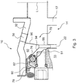
- a baseplate 32 of an air dryer cartridge device 10 (as shown in Fig. 1 ) having a sieve element 24 connected to it is shown in cross-section.
- the air dryer cartridge 10 is tightly connected to a base part 15 of the air treatment system 14 by means of a sealing interface 70.
- the sealing interface 70 comprises at least one sealing means 76, has at least one sheet metal element 78 on the air drying cartridge side and at least one projection 80 on the base part 15, the projection 81 on the base part 15 having a bearing surface 82 for the sealing means 76, which bearing surface is directed radially inwards relative to the longitudinal axis L of the base part 15 and the air drying cartridge 10, the sheet metal element 78 being fastened on the air-drying cartridge side, and the sealing means 76 pressing against the bearing surface 82 in the assembled state, a holding element 90 further being provided which, in the assembled state, is arranged in such a way that the sealing means 76 is held between the sheet metal element 78 and the bearing surface 82 at least partially in the axial and radial direction relative to the longitudinal axis L by means of the sheet metal element 78 and the holding element 90.
- an O-ring can be used as a sealing means 76 between the air dryer cartridge 10 and the air treatment system 14 a sealing means 76 between the air dryer cartridge 10 and the air treatment system 14 an
- the sieve element 24 which is connected to the baseplate 32 of an air dryer cartridge device 10 comprises a ring shaped part 92 such as a support part extending symmetrically about a longitudinal axis L of the air dryer cartridge 10.
- the ring shaped part 92 may extend over any angle between 10° and 360°, including 25°, 45°, 60°, 90°, 120° and multiples thereof about the longitudinal axis of the air dryer cartridge 10.
- the ring shaped part 92 of the sieve element 24 comprises two lateral walls 94, 96 comprising in a cross-section an angle of about 30° t0 45° with respect to each other.
- the ring shaped part 92 shown represents just one example and any suitable shape of the lateral walls can be used including a straight, rounded or other shape.
- the sheet metal element 78 connected to the baseplate 32 of the air dryer cartridge 10 comprises a circular main section and a lateral section having a shape of a ring.
- the lateral section which represents a contact surface for the sealing means 76 is arranged symmetrically with respect to the longitudinal axis of the air dryer cartridge 10 and extends from the baseplate 32 downwards in direction of the air treatment system 14.
- An end segment of one of the walls 94 of the ring shaped part 92 of the sieve element 24 rests on the lateral section of the sheet metal element 78, while the other lateral wall 96 of the ring shaped part 92 of the sieve element 24 comprises an end segment or flap that is connected to the baseplate 32 of the air dryer cartridge 10.
- Both lateral ring-shaped walls of the ring shaped part 92 of the sieve element 24 are movably connected with the sheet metal element 78 and the baseplate 32, respectively, so that the sieve element 24 can be rotated with respect to the air dryer cartridge 10.
- the connection between the lateral walls of the ring shaped part 92 of the sieve element 24 and the air dryer cartridge device 10 can be provided, for example, by clip connections between the lateral walls of the ring shaped part 92 and the sheet metal element 78 and the baseplate 32, respectively.
- other connections can be used as well such as a rotatable support connected to a rotatable axle or hinge of the air dryer cartridge device 10 or the baseplate 32.
- a box shaped part 98 of the sieve element 24 extends from the ring shaped part 92 of the sieve element 24 into a vent line 22 or respective seat of the air treatment system 14.
- the box shaped part 98 of the sieve element 24 is connected at one of its sides to the lateral walls 94, 96 of the ring shaped part 98 of the sieve element 24.
- the lateral walls 94, 96 of the ring shaped part 92 of the sieve element 24 are connected at their ends to opposite sides of the box shaped part 98 of the sieve element 24.
- the box shaped part 98 of the sieve element 24 comprises at least one sieve in one of its walls, but may also comprise two or more sieves that are provided on opposing sides or adjacent sides of the box shaped part 98 of the sieve element 24 as appropriate.
- the sides or walls of the box shaped part 98 of the sieve element 24 together form a cage which air passing from the air dryer cartridge 10 to the air treatment system 14 including air coming from the compressor through the compressed air delivery line 17 or passing through an opening such as an inlet 50 in the air dryer cartridge 10 must traverse. Particles and oil contained in the air that traverses the at least one sieve of the box shaped part 98 are held back by the sieve.
- the box shaped part 98 may comprise one or more plane walls or rounded walls and may also comprise a cylindrical wall.
- the sieve element 24 rotates with respect to the air dryer cartridge 10 while the air dryer cartridge 10 is getting connected to the air treatment system 10 by means of a thread formed in or on the baseplate 32 of the air dryer cartridge 10. Simultaneously, the box shaped part 98 of the sieve element 24 remains at a fixed position and inserted into the vent line 22 or a corresponding seat thereof without rotating with respect to the air treatment system 14.
- the movable connection of the sieve element 24 and the air dryer cartridge device 10 is particularly suitable for air dryer cartridge devices having a spin-on connection design without any limitation to it.
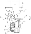
- FIG. 4 Another embodiment of the invention is described in the following with reference to Fig. 4 .
- the same reference numerals are used in Figs. 3 and 4 for the same or corresponding parts. Only divergent features with respect to the embodiment shown in Fig. 3 will be described in the following.
- both lateral ring-shaped walls 94, 96 of the ring shaped part 98 of the sieve element 24 are fixedly connected with the baseplate 32 so that the sieve element 24 is stably mounted to the air dryer cartridge 10.
- the lateral ring-shaped walls 94, 96 of the ring shaped part 98 of the sieve element 24 can be configured for clipping into one or more openings such as inlets 50 in the baseplate 32.
- other connections can be provided as well including a screw connection, bolted connection, rivet connection, solder connection, welding connection, adhesive connection etc.
- a box shaped part 98 of the sieve element 24 which can correspond to the box shaped part 98 described with regard to the embodiment shown in Fig. 3 extends from the ring shaped part 92 of the sieve element 24 into a ring shaped groove connected and partly correspond to a vent line 22 of the air treatment system 14.
- both the air dryer cartridge 10 and the sieve element 24 are rotated when the air dryer cartridge 10 gets connected to the air treatment system 10 by means of a thread formed in or on the baseplate 32 of the air dryer cartridge 10.
- the box shaped part 98 of the sieve element 24 moves along a circular groove formed in the air treatment system 14 which in Fig. 4 overlaps and corresponds to the upper section of the vent line 22.
- the box shaped part 98 of the sieve element 24 When the air dryer cartridge 10 reaches its final position in the air treatment system 14, the box shaped part 98 of the sieve element 24 must be positioned circumferentially in the groove at the vent line 22 of the air treatment system 14 so that air entering or exhausted by the vent line 22 has to transverse at least one of the sieves of the sieve element 24.
- other designs of the air treatment system 14 without providing groove for the box shaped part 98 of the sieve element 24 can be conceived as well.
- the box shaped part 98 of the sieve element 24 could be replaced by or combined with a different sieve element 24 such as for example a planar sieve element comprising or consisting of a single sieve only or a box-shaped, for example cylindrical sieve element comprising one or more, in particular, cylindrical sieves.
- a different sieve element 24 such as for example a planar sieve element comprising or consisting of a single sieve only or a box-shaped, for example cylindrical sieve element comprising one or more, in particular, cylindrical sieves.
- FIG. 5 describes another embodiment of the invention.
- a top part of the air dryer cartridge 10 is shown which is designed for a connection with an air treatment system 14.
- a sieve element 24 Connected to the top part of the air dryer cartridge 10 is a sieve element 24 using a clipping connection comprising one part formed by a number of lugs or bars 102 provided on the air dryer cartridge 10 and another part formed by a corresponding number of openings 104 for receiving the lugs 102 provided on the sieve element 24.
- a clipping connection comprising one part formed by a number of lugs or bars 102 provided on the air dryer cartridge 10 and another part formed by a corresponding number of openings 104 for receiving the lugs 102 provided on the sieve element 24.
- four pairs of lugs 102 and openings 104 can be provided on opposing sides of the sieve element 24.
- the sieve element 24 is movable along an axis of the air dryer cartridge device 10 about a predetermined distance. This configuration permits the sieve element 24 to correctly adjust in its position in a seat provided in the air treatment system 14, in particular, to adjust its longitudinal position and extension, and ensures a tight seat in a recess in the air treatment system. Thus air can be prevented from bypassing the sieve element.
- the sieve element 24 comprises at least one sieve 106 provided in a top surface thereof.
- the sieve element 24 comprises a steeple-like structure which is configured to fit into a corresponding recess provided in the air treatment system 14.
- at least one sieve 108 is provided in the top part of the air dryer cartridge device 10 below the at least one sieve of the sieve element 24.
- the sieve element 24 comprises an expandable lateral wall 110 supporting a top wall of the sieve element 24 which comprises the sieve 106.
- the expandable lateral wall 110 which overlaps with a corresponding lateral wall 111 extending from the top part of the air dryer cartridge 10. Due to the expandable lateral wall 110 overlapping the wall 111 of the air dryer cartridge 10 the sieve element 24 can be displaced with respect to top part of the air dryer cartridge 10. Hence, the position and volume of the sieve element 24 can be varied without air bypassing the sieve element 24.
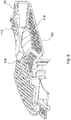
- Figure 6 shows a further embodiment of an air dryer cartridge device 10 comprising a sieve element 24.
- the sieve element 24 of the embodiment shown in Fig. 6 is fixedly connected to a top part of the air dryer cartridge 10.
- the sieve element of this embodiment may be integrated into the air dryer cartridge device 10.
- the sieve element 24 may be connected to the air dryer cartridge device 10 by a clip connection, screws, etc.
- the sieve element 24 comprises a section comprising a top part 112 and bottom part 114 which are connected to each other and form a closed volume, box or cage. In this section a first sieve 106 of the top part 112 and a second sieve 108 of the bottom part 114 are arranged on top of each other.
- the upper surface of the sieve element 24 is configured to match a corresponding recess in the air treatment system 14, when the air dryer cartridge device 10 comprising the sieve element 24 is assembled to it.
- the sieve element 24 comprises a single sieve only.
- FIG. 7 another embodiment of an air dryer cartridge device 10 comprising a connected sieve element 24 is illustrated.
- the sieve element 24 can be connected to the air dryer cartridge device 10 in a manner which permits a rotation of the sieve element 24 with respect to the air dryer cartridge device 10 so that the air dryer cartridge device 10 can be configured with a spin-on configuration for an assembly with the air treatment system 14.
- an immovable connection between the air dryer cartridge device and the sieve element 24 such as a clip connection or screws can be provided alternatively.
- the sieve element 24 comprises a top part 112 and bottom part 114 which are connected to each other forming a closed volume there between.
- the top part 112 as well as the bottom part 114 each comprises a sieve 106, 108 in parallel surfaces thereof.
- the sieve element 24 is configured to be connected to or integrated in the top part of an air dryer cartridge 10.
Landscapes
- Chemical & Material Sciences (AREA)
- Engineering & Computer Science (AREA)
- Analytical Chemistry (AREA)
- General Chemical & Material Sciences (AREA)
- Oil, Petroleum & Natural Gas (AREA)
- Chemical Kinetics & Catalysis (AREA)
- Drying Of Gases (AREA)
Abstract
Description
- The invention relates to an air drying device for a compressed air treatment system of a vehicle, in particular a utility vehicle, with a housing and an air drying means contained in the housing.
- Air drying devices such as air dryer cartridges are used as wearing parts within compressed air supply or compressed air treatment systems especially in the commercial vehicle sector. There they are used to clean the generated compressed air from oil and dirt particles and to dry the compressed air.
- A
conventional dryer cartridge 10 for a compressed air treatment system of a vehicle as shownFig. 1 comprises ahousing 16 and a base plate, which together in the assembled state of the air dryer cartridge define a volume of the air dryer cartridge. The cartridge comprises disposed within the volume as a part of an air drying means a desiccant 38 filleddesiccant box 20 which is arranged in thehousing 16. - The base plate comprises an
air inlet 50 and anair outlet 52. An O-ring 44 and a sealingring 40 seal between the base plate and thedesiccant box 20. The sealingring 40 can comprise a rubber lip seal, with arubber lip 48 acting as a non-return valve. In alternative devices the sealingring 40 may consist of another O-ring. - The
sealing ring 40 is mechanically or chemically connected to thedesiccant box 20, whereby therubber lip 48 has a defined opening and closing characteristic. In particular, therubber lip 48 opens when there is excess pressure in theair dryer cartridge 10 and thus acts as a safety valve. Thedesiccant box 20 is limited in its axial direction of extension by a first air filter 30. Optionally, asecond air filter 31 or a fleece can be provided which retain the desiccant 38 inside thedesiccant box 20. Anoptional compression spring 34 and agranulate cover 36 can also be provided in the upper area or lower area of theair dryer cartridge 10 to compress the desiccant 38 inside thedesiccant box 20. Thegranulate cover 36 is particularly air-permeable. - A combination filter, for example in the form of a coalescing
filter 26, extends in the axial direction around the lower half of thedesiccant box 20 and is fixed in the radial direction by asleeve 28 to a supporting structure of thedesiccant box 20. The coalescingfilter 26 divides theair dryer cartridge 10 into a pre-filter area and an after-filter area. The task of the coalescingfilter 26 during a compressed air conveying phase is to hold oil and dirt particles as well as emulsion droplets on an inflow surface, to store liquid oil and to convert the finest oil droplets and aerosols into liquid oil by a coalescing effect and to separate them. The design of the outflow surface and the filter design results in a defined ratio of air outflow velocity and oil droplet size. This ratio guarantees that no oil droplets enter thedesiccant box 20 via the after-filter area and thus shorten the service life of theair dryer cartridge 10 and downstream consumers. -
Air guide elements 46 can be provided that project radially from thedesiccant box 20 into the coalescingfilter 26 and prevent the coalescingfilter 26 from being bypassed by incoming air. The sealing during a compressed air conveying phase between the pre-filter area and the after-filter area is thus achieved by a special sealing geometry consisting of theair guide elements 46 in conjunction with theouter sleeve 28. - According to the example shown in
Fig. 1 a projection 72 is disposed on thesupport member 18. The projection 72 is surrounded by afirst seal 68 which seals between thesupport member 18 and the cartridge housing and asecond seal 73 which seals between thesupport member 18 and a housing of anair treatment system 14 as shown infigure 2 . This arrangement may, for example, be intended for mounting theair dryer cartridge 10 to theair treatment system 14 by means of a bayonet ring. - For spin-on designs, the
air dryer cartridge 10 can comprise means for a thread connection with theair treatment system 14. For example, the projection 72 can be omitted and a thread symmetrically arranged with respect to the longitudinal axis of theair dryer cartridge 10 can be provided in thesupport member 18 which can be fitted to a corresponding thread of theair treatment system 14 to mount theair dryer cartridge 10 to theair treatment system 14. -
Figure 2 shows a section of a schematicair treatment system 14 to which theair dryer cartridge 10 can be assembled. Theair treatment system 14 has acompressed air inlet 12 to which a compressor can be connected. In addition, theair treatment system 14 includes anexternal filling connection 75 which can also be used to supply compressed air from an external compressed air source to theair treatment system 14, for example for service purposes in a workshop. Furthermore, adata bus connection 77 is provided via which theair treatment system 14 can communicate with other subsystems of the commercial vehicle, such as an engine control system. Theair treatment system 14 comprises a compressedair delivery line 17, which connects thecompressed air inlet 12 with the replaceableair dryer cartridge 10. - The
air dryer cartridge 10 cleans the conveyed compressed air of oil and dirt particles and removes moisture from it. Air processed by theair dryer cartridge 10 is passed downstream of theair dryer cartridge 10 via acheck valve 47. A multi-circuitprotection valve connection 71 is indicated, whereby the multi-circuit protection valve not shown can be a component separate from the compressedair treatment system 10 or integrated into the compressedair treatment system 10. When the desiccant capacity of theair dryer cartridge 10 is exhausted, processed compressed air bypassing thecheck valve 47 can regenerate theair dryer cartridge 10 by reversing the flow direction via aregeneration line 58, anothercheck valve 49 and athrottle 51. In the process, oil and dirt particles collected in theair dryer cartridge 10 as well as moisture stored in the desiccant are rinsed out of theair dryer cartridge 10. As shown infigure 2 , the regeneration air continues to flow backwards through the compressedair delivery line 17 to abranching point 21 and from there via avent line 22 to avent 80. In thevent line 22 there is adrain valve 19, which can be designed as a 2/2-way valve, for example. Between thebranch point 21 and thedrain valve 19 there is asieve element 24 which retains coarse dirt particles. - Usually, the
sieve element 24 which can comprise an oil carbon sieve protects thedrain valve 19 against cracked oils, which damage or block thedrain valve 19, which can lead to permanent leakages and air loss of the wholeair treatment system 10. These cracked oils occur mainly, if a bad compressor is used, which burns oil due to too high operating temperature. - The regeneration cycle can be controlled with a
regeneration solenoid valve 56, which is arranged in theregeneration line 58 and can be designed as a 3/2-way valve, for example. Aclosing spring 93 of thedrain valve 19 can be pre-tensioned via acontrol line 53, which branches off from theregeneration line 58 at abranch point 55, in order to adjust the pneumatic opening pressure of thedrain valve 19, for example between an opening pressure of approx. 9.5 to 10 bar if thecontrol line 53 is pressureless and an opening pressure of approx. 16 to 17 bar if thecontrol line 53 is pressurized. Thedrain valve 19 can be pneumatically actuated via afurther control line 60 in which asolenoid valve 62, designed as a 3/2-way valve for example, is arranged. In order to discharge the regeneration air via thevent 80, both theregeneration solenoid valve 56 and thesolenoid valve 62 can be actuated simultaneously, so that the regeneration air reaches thevent 80 via thesieve element 24 and thedrain valve 19 in order to exit the system there. Thefurther control line 60 can have afurther branch point 91, via which afurther valve device 74 can be controlled, which in turn can put an unrepresented compressor, which provides the compressed air at thecompressed air inlet 12, into an energy-saving operating state. In particular, thevalve device 74 can enable particularly fast venting of theother control line 60 in order to change the operating state of the compressor more quickly. In such an energy-saving state, thedrain valve 19 is simultaneously activated, so that a normally reduced compressed air flow rate of the compressor exits the system directly from the compressed air inlet via thesieve element 24 and thedrain valve 19 via thevent 80. For example, a reduced compressed airflow rate may be approximately 20 percent of the normally conveyed compressed air volume. - As indicated in
Figure 2 ,vent 80 can be connected to other components of theair treatment system 14, which are not shown, via anadditional ventilation line 59. These components can also usevent 80 to expel compressed air from the system. Furthermore, the venting indicated on theregeneration solenoid valve 56 and thesolenoid valve 62 can also be coupled with thevent 80, whereby the explicit representation of corresponding connecting lines has been omitted for a better overview. Theair treatment system 14 comprises acontrol unit 64, which can control theregeneration solenoid valve 56 and thesolenoid valve 62 and can be coupled to other subsystems of the commercial vehicle via thedata bus connection 77. Also indicated are aheater 69 and apressure sensor 66, which is controlled by thecontrol unit 64 or via which thecontrol unit 64 receives information on the pressure levels prevailing in theair treatment system 14.Heater 69 can be used in particular to prevent pressure lines from freezing. Thepressure sensor 66 is only to be understood as an example for a whole number of pressure sensors which can measure the pressure in theair treatment system 14 at various points. In particular, 22 pressure sensors can be arranged upstream and downstream of thesieve element 24 in the vent line to determine a back pressure drop on thesieve element 24 when thedrain valve 19 is open. In this way, a blockage of thesieve element 24 can be detected which would hinder the escape of the compressed air during a regeneration cycle, whereby this blockage can be a change criterion. Thedrain valve 19 also serves as a safety valve to prevent a dangerous increase in pressure in theair treatment system 14. A control line 95 is provided for this purpose, which opens the drain valve when an adjustable safety pressure is exceeded. - According to the state of the art, it is known to use an oil carbon sieve as
sieve element 24, which is intended as a separate piece and installed in theair treatment system 14. An example of an oil carbon sieve is described in European patent applicationEP 2505444 A2 . However, as a shortcoming theair dryer cartridge 10 and thesieve element 24 have to be mounted to theair treatment system 14 and be replaced as separate pieces, which is cumbersome. Furthermore, it was an experience that the sieve moves away from its mounting position during operation of the vehicle in which theair treatment system 14 is mounted, for example, because of vibrations caused by the movement of the vehicle. Furthermore, from the view of the assembler thesieve element 24 can be located in theair treatment system 14 behind theair dryer cartridge 10 so that it is not visible during the assembling of theair dryer cartridge 10. - Also the dismounting of a
conventional sieve element 24 can be cumbersome, since it is usually oil-contaminated after use and furthermore can be relatively small so that it is difficult to grab. - It is an object of the present invention to provide an improved device for drying air of an air treatment system which overcomes the disadvantages of prior art, in particular, avoids a cumbersome and faulty mounting or dismounting procedure of the sieve element.
- According to the present invention the problem is solved by an air dryer cartridge having the features of
claim 1. - According to the invention the problem is solved by a device for drying air of an air treatment system of a vehicle also denoted as an air dryer cartridge, comprising a housing, an air drying means contained in the housing, an air inlet configured to receive air from the air treatment system and an air outlet for outputting air to the air treatment system, a connection means configured for mounting the device to the air treatment system, wherein the device is configured to be connected to a sieve element that can be arranged in an stream of air between the air treatment system and the device.
- The air dryer cartridge of the present invention has the advantage that it can be mounted together with the sieve element as one part to the air treatment system, so that the risk that the sieve displaces from its intended position in the air treatment system during or after the mounting of the device can be avoided even if the sieve element is hidden behind the device and not visible by an assembler during the mounting. In addition, mounting time of the air dryer cartridge device and the sieve element can be reduced since both parts are combined into one part and are mounted simultaneously as one piece.
- Providing the sieve element connected to the cartridge as one piece also has the advantage that both parts can be replaced together without the need to touch or grab the sieve element which is frequently contaminated with oil after its use.
- According to an embodiment the connection means is at least a part of one of a bayonet connector, a thread connection, a plug connection. These connection means can be used for air dryer cartridge devices being designed for different types of mounting mechanisms including spin-on designs and thread less mounting designs.
- According to another embodiment the device comprises at least one of a magnet, a thread, a part of a clip mechanism configured for connecting a sieve element to it. These connection means provide for a reliable but detachable connection between the device and the sieve element.
- According to a further embodiment the device is configured or comprises a connection part for connecting the sieve element to the device so that the sieve element can be mounted to the device with the sieve element being rotatable about an axis of the device. This configuration permits to design the device with a spin-on connection means such as a thread for assembly to the air treatment system, wherein the sieve element can be introduced into a recess or seat connected to a vent line of the air treatment system, and remains circumferentially in rest, while the device is getting connected to the air treatment system by screwing it into a corresponding thread seat of the air treatment system. During this connection process the sieve element, which remains circumferentially in rest, together with the device being screwed into the thread seat of the air treatment system, is advanced into the recess or seat connected to the vent line of the air treatment system.
- According to another embodiment the device is configured or comprises a connection part to connect a sieve element to the device so that the sieve element is mounted to the device in such a manner that the sieve element is movable along an axis, in particular, the longitudinal axis of the device about a predetermined distance. This configuration permits the sieve element to correctly adjust its position in the air treatment system and, in particular, permits to adjust its longitudinal position and extension, which ensures a tight seat in a recess in the air treatment system. Thus air can be prevented from bypassing the sieve element.
- According to yet another embodiment the sieve element comprises one or more expandable lateral walls supporting a top wall of the sieve element which can be displaced with respect to a top side of the device so that the volume covered by the sieve element can be varied. One or more sieves can be provided in one or more of the top wall and the one or more expandable lateral walls of the sieve element. This embodiment has the advantage that the adjustment of the size of the sieve element and position of the sieve can be automatically performed and bypassing of air can be prevented even under adverse or harsh operation conditions.
- According to still another embodiment the device comprises a sealing means configured to seal the device against the air treatment system when the device is mounted to the air treatment system. The sealing means can be an O-ring or a lip provided in or connected to a base plate of the device. According to another embodiment the sieve element connected to the device is positioned within a sealed volume between the air treatment system and the device sealed by the sealing means. Also sealed by the sealing means, the base plate of the device may comprise at least one of an air inlet and an air outlet connected to respective lines such as a vent line and/or an air delivery line of the air treatment system for exchange of an airstream between the device and the air treatment system through the sieve element.
- According to a further embodiment the device further comprises the sieve element integrally connected to the device. The sieve element may comprise one or more sieves.
- According to a still another embodiment the device comprises the sieve element, wherein the sieve element comprises at least one of a magnet, a thread, a part of a clip mechanism configured for connecting the sieve element to a respective complementary part of the device.
- According to a further embodiment the sieve element or a part thereof comprises a symmetric, in particular rotation symmetric design, the shape of a circular arc or a ring shape, the sieve element or the part thereof being symmetric with respect to a longitudinal axis of the device. This configuration is suitable for a device having a spin on design, wherein the sieve element or a part thereof is configured so that it is movable with respect to the device when it is connected to it so that the sieve element remains in a circumferentially fixed position with respect to the air treatment system, when the device is screwed into a thread or seat of the air treatment system.
- According to a further embodiment the sieve element comprises a shape of a box comprising at least two sieves arranged in two adjacent or opposite sides of the box, the box being configured so that the stream of air passing between the air treatment system and the device passes through at least one of the sieves of the sieve element. This design has the advantage that it provides a high filtering efficiency due to a use of more than one sieve and prevents a bypassing of particles from either side of the sieve element. According to an embodiment at least one of the sides of the box -shaped sieve element can be open or have an opening.
- According to an embodiment the sieve element comprises one or more expandable lateral walls supporting or connected to a top wall of the sieve element which can be displaced with respect to the bottom wall of the sieve element so that the volume of the box shaped sieve element can be varied.
- According to a further embodiment the sieve element comprises a sieve comprising a carbon comprising substance. Alternatively, the sieve may comprise other components or substances having a good filtering efficiency. The sieve can also have a structure including multiple openings or a mesh or grating structure.
- According to yet another embodiment the device comprises a first sieve integrated in a top section thereof and a second sieve integrated in the sieve element connected to the device above the top section, the sieve element being configured so that the stream of air passing between the air treatment system and the device passes through at least one of the first and second sieves. According to this embodiment at least one of the sieves can be removable or replaceable, while at least one other sieve forms an integral part of the device.
- According to a further embodiment the device is configured so that during mounting of the device to the air treatment system or in its mounted state the sieve element is correctly positioned in a recess or seat of the air treatment system so that the stream of air passing between the air treatment system and the device passes through the sieve element. This can be achieved by using a geometry or shape for the sieve element and the recess or seat of the air treatment system having shape conformity. Accordingly, undesirable bypassing of the sieve element by air can be prevented even when the device is used under harsh or adverse operation conditions.
- According to still another embodiment the device is configured so that the sieve element is connected appropriately to a vent line of the air treatment system when the device is mounted to the air treatment system so that the stream of air passing between the air treatment system and the device passes through the sieve element.
- According to still another embodiment the device is configured to pull out the sieve element from the air treatment system during dismounting of the device from the air treatment system. This permits an easy replacement of the sieve element together with the device, while any contamination with oil of persons handling the device can be prevented.
- The invention also refers to a sieve element for a device for drying air of an air treatment system of a vehicle, the sieve element configured to be physically connected with a device for drying air according to one or more of the device and embodiments previously described.
- The sieve element can be configured like and have the characteristic of the sieve element described above.
- According to an embodiment the sieve element comprises at least one of a magnet, a thread, at least a part of a clip mechanism configured for connecting the sieve element to a respective complementary part of the device.
- According to another embodiment the sieve element or a part thereof comprises a symmetric, in particular rotation symmetric design, the shape of a circular arc or a ring shape, the sieve element or the part thereof being symmetric with respect to a longitudinal axis of the device.
- According to another embodiment the sieve element comprises a shape of a box comprising at least two sieves arranged in two adjacent or opposite sides of the sieve element, the sieve element being configured so that the stream of air passing between the air treatment system and the device passes through at least one of the sieves.
- According to yet another embodiment the sieve element comprises one or more expandable lateral walls supporting a top wall of the sieve element which can be displaced with respect to a bottom wall of the sieve element so that the volume of the box shaped sieve element can be varied.
- According to another embodiment the sieve element comprises a sieve comprising a carbon comprising substance.
- Further details, advantages and aspects of the invention will result from the description of exemplifying embodiments of the invention with reference to the drawing in which
- Fig. 1
- shows an example of an air dryer cartridge device;
- Fig. 2
- shows a schematic example of a section of an air treatment system;
- Fig. 3
- shows a detail of an air dryer cartridge device according to an embodiment;
- Fig. 4
- shows a detail of an air dryer cartridge device according to another embodiment;
- Fig. 5
- shows a detail of an air dryer cartridge device according to a further embodiment;
- Fig. 6
- shows a detail of an air dryer cartridge device according to still another embodiment; and
- Fig. 7
- shows a detail of an air dryer cartridge device according to yet another embodiment.
- Embodiments of the invention will be described in the following with reference to the drawings. In
Fig. 3 abaseplate 32 of an air dryer cartridge device 10 (as shown inFig. 1 ) having asieve element 24 connected to it is shown in cross-section. Theair dryer cartridge 10 is tightly connected to abase part 15 of theair treatment system 14 by means of a sealinginterface 70. - The sealing
interface 70 comprises at least one sealing means 76, has at least onesheet metal element 78 on the air drying cartridge side and at least oneprojection 80 on thebase part 15, theprojection 81 on thebase part 15 having a bearingsurface 82 for the sealing means 76, which bearing surface is directed radially inwards relative to the longitudinal axis L of thebase part 15 and theair drying cartridge 10, thesheet metal element 78 being fastened on the air-drying cartridge side, and the sealing means 76 pressing against the bearingsurface 82 in the assembled state, a holdingelement 90 further being provided which, in the assembled state, is arranged in such a way that the sealing means 76 is held between thesheet metal element 78 and the bearingsurface 82 at least partially in the axial and radial direction relative to the longitudinal axis L by means of thesheet metal element 78 and the holdingelement 90. As a sealing means 76 between theair dryer cartridge 10 and theair treatment system 14 an O-ring can be used. - The
sieve element 24 which is connected to thebaseplate 32 of an airdryer cartridge device 10 comprises a ring shapedpart 92 such as a support part extending symmetrically about a longitudinal axis L of theair dryer cartridge 10. The ring shapedpart 92 may extend over any angle between 10° and 360°, including 25°, 45°, 60°, 90°, 120° and multiples thereof about the longitudinal axis of theair dryer cartridge 10. The ring shapedpart 92 of thesieve element 24 comprises twolateral walls part 92 shown represents just one example and any suitable shape of the lateral walls can be used including a straight, rounded or other shape. - The
sheet metal element 78 connected to thebaseplate 32 of theair dryer cartridge 10 comprises a circular main section and a lateral section having a shape of a ring. The lateral section which represents a contact surface for the sealing means 76 is arranged symmetrically with respect to the longitudinal axis of theair dryer cartridge 10 and extends from thebaseplate 32 downwards in direction of theair treatment system 14. An end segment of one of thewalls 94 of the ring shapedpart 92 of thesieve element 24 rests on the lateral section of thesheet metal element 78, while the otherlateral wall 96 of the ring shapedpart 92 of thesieve element 24 comprises an end segment or flap that is connected to thebaseplate 32 of theair dryer cartridge 10. Both lateral ring-shaped walls of the ring shapedpart 92 of thesieve element 24 are movably connected with thesheet metal element 78 and thebaseplate 32, respectively, so that thesieve element 24 can be rotated with respect to theair dryer cartridge 10. The connection between the lateral walls of the ring shapedpart 92 of thesieve element 24 and the airdryer cartridge device 10 can be provided, for example, by clip connections between the lateral walls of the ring shapedpart 92 and thesheet metal element 78 and thebaseplate 32, respectively. However, other connections can be used as well such as a rotatable support connected to a rotatable axle or hinge of the airdryer cartridge device 10 or thebaseplate 32. - A box shaped
part 98 of thesieve element 24 extends from the ring shapedpart 92 of thesieve element 24 into avent line 22 or respective seat of theair treatment system 14. The box shapedpart 98 of thesieve element 24 is connected at one of its sides to thelateral walls part 98 of thesieve element 24. Thelateral walls part 92 of thesieve element 24 are connected at their ends to opposite sides of the box shapedpart 98 of thesieve element 24. Generally, the box shapedpart 98 of thesieve element 24 comprises at least one sieve in one of its walls, but may also comprise two or more sieves that are provided on opposing sides or adjacent sides of the box shapedpart 98 of thesieve element 24 as appropriate. The sides or walls of the box shapedpart 98 of thesieve element 24 together form a cage which air passing from theair dryer cartridge 10 to theair treatment system 14 including air coming from the compressor through the compressedair delivery line 17 or passing through an opening such as aninlet 50 in theair dryer cartridge 10 must traverse. Particles and oil contained in the air that traverses the at least one sieve of the box shapedpart 98 are held back by the sieve. The box shapedpart 98 may comprise one or more plane walls or rounded walls and may also comprise a cylindrical wall. - Due to its movable, in particular rotatable connection to the
baseplate 32 of theair dryer cartridge 10, thesieve element 24 rotates with respect to theair dryer cartridge 10 while theair dryer cartridge 10 is getting connected to theair treatment system 10 by means of a thread formed in or on thebaseplate 32 of theair dryer cartridge 10. Simultaneously, the box shapedpart 98 of thesieve element 24 remains at a fixed position and inserted into thevent line 22 or a corresponding seat thereof without rotating with respect to theair treatment system 14. Hence, the movable connection of thesieve element 24 and the airdryer cartridge device 10 according to this embodiment is particularly suitable for air dryer cartridge devices having a spin-on connection design without any limitation to it. - Another embodiment of the invention is described in the following with reference to
Fig. 4 . The same reference numerals are used inFigs. 3 and4 for the same or corresponding parts. Only divergent features with respect to the embodiment shown inFig. 3 will be described in the following. - In
Fig. 4 both lateral ring-shapedwalls part 98 of thesieve element 24 are fixedly connected with thebaseplate 32 so that thesieve element 24 is stably mounted to theair dryer cartridge 10. For example, the lateral ring-shapedwalls part 98 of thesieve element 24 can be configured for clipping into one or more openings such asinlets 50 in thebaseplate 32. However, other connections can be provided as well including a screw connection, bolted connection, rivet connection, solder connection, welding connection, adhesive connection etc. - A box shaped
part 98 of thesieve element 24 which can correspond to the box shapedpart 98 described with regard to the embodiment shown inFig. 3 extends from the ring shapedpart 92 of thesieve element 24 into a ring shaped groove connected and partly correspond to avent line 22 of theair treatment system 14. - Due to its fixed connection to the
baseplate 32 of theair dryer cartridge 10, both theair dryer cartridge 10 and thesieve element 24 are rotated when theair dryer cartridge 10 gets connected to theair treatment system 10 by means of a thread formed in or on thebaseplate 32 of theair dryer cartridge 10. During the mounting process the box shapedpart 98 of thesieve element 24 moves along a circular groove formed in theair treatment system 14 which inFig. 4 overlaps and corresponds to the upper section of thevent line 22. When theair dryer cartridge 10 reaches its final position in theair treatment system 14, the box shapedpart 98 of thesieve element 24 must be positioned circumferentially in the groove at thevent line 22 of theair treatment system 14 so that air entering or exhausted by thevent line 22 has to transverse at least one of the sieves of thesieve element 24. However, other designs of theair treatment system 14 without providing groove for the box shapedpart 98 of thesieve element 24 can be conceived as well. - Also other assemblies than spin-on connections for connecting the air
dryer cartridge device 10 including thesieve element 24 to theair treatment system 14 can be provided as alternatives or in combination with the spin-on connection described with respect to the embodiments shown inFigs. 3 and4 such as a bayonet connection or plug connection etc. - In both embodiments shown in
Figs. 3 and4 , respectively, the box shapedpart 98 of thesieve element 24 could be replaced by or combined with adifferent sieve element 24 such as for example a planar sieve element comprising or consisting of a single sieve only or a box-shaped, for example cylindrical sieve element comprising one or more, in particular, cylindrical sieves. -
Figure 5 describes another embodiment of the invention. InFig. 5 a top part of theair dryer cartridge 10 is shown which is designed for a connection with anair treatment system 14. Connected to the top part of theair dryer cartridge 10 is asieve element 24 using a clipping connection comprising one part formed by a number of lugs or bars 102 provided on theair dryer cartridge 10 and another part formed by a corresponding number ofopenings 104 for receiving thelugs 102 provided on thesieve element 24. For example, four pairs oflugs 102 andopenings 104 can be provided on opposing sides of thesieve element 24. Due to thelugs 102 being provided in theopenings 104 and hooks provided at the end of thelugs 102 thesieve element 24 is movable along an axis of the airdryer cartridge device 10 about a predetermined distance. This configuration permits thesieve element 24 to correctly adjust in its position in a seat provided in theair treatment system 14, in particular, to adjust its longitudinal position and extension, and ensures a tight seat in a recess in the air treatment system. Thus air can be prevented from bypassing the sieve element. - The
sieve element 24 comprises at least onesieve 106 provided in a top surface thereof. Next to thesieve 106 thesieve element 24 comprises a steeple-like structure which is configured to fit into a corresponding recess provided in theair treatment system 14. Furthermore, at least onesieve 108 is provided in the top part of the airdryer cartridge device 10 below the at least one sieve of thesieve element 24. - In addition, the
sieve element 24 comprises an expandablelateral wall 110 supporting a top wall of thesieve element 24 which comprises thesieve 106. The expandablelateral wall 110 which overlaps with a correspondinglateral wall 111 extending from the top part of theair dryer cartridge 10. Due to the expandablelateral wall 110 overlapping thewall 111 of theair dryer cartridge 10 thesieve element 24 can be displaced with respect to top part of theair dryer cartridge 10. Hence, the position and volume of thesieve element 24 can be varied without air bypassing thesieve element 24. -
Figure 6 shows a further embodiment of an airdryer cartridge device 10 comprising asieve element 24. In contrast to thesieve element 24 shown inFig. 5 thesieve element 24 of the embodiment shown inFig. 6 is fixedly connected to a top part of theair dryer cartridge 10. For example, the sieve element of this embodiment may be integrated into the airdryer cartridge device 10. Alternatively, thesieve element 24 may be connected to the airdryer cartridge device 10 by a clip connection, screws, etc. Thesieve element 24 comprises a section comprising atop part 112 andbottom part 114 which are connected to each other and form a closed volume, box or cage. In this section afirst sieve 106 of thetop part 112 and asecond sieve 108 of thebottom part 114 are arranged on top of each other. The upper surface of thesieve element 24 is configured to match a corresponding recess in theair treatment system 14, when the airdryer cartridge device 10 comprising thesieve element 24 is assembled to it. In another adjacent section, thesieve element 24 comprises a single sieve only. - In
Fig. 7 another embodiment of an airdryer cartridge device 10 comprising aconnected sieve element 24 is illustrated. Thesieve element 24 can be connected to the airdryer cartridge device 10 in a manner which permits a rotation of thesieve element 24 with respect to the airdryer cartridge device 10 so that the airdryer cartridge device 10 can be configured with a spin-on configuration for an assembly with theair treatment system 14. However, an immovable connection between the air dryer cartridge device and thesieve element 24 such as a clip connection or screws can be provided alternatively. Thesieve element 24 comprises atop part 112 andbottom part 114 which are connected to each other forming a closed volume there between. Thetop part 112 as well as thebottom part 114 each comprises asieve sieve element 24 is configured to be connected to or integrated in the top part of anair dryer cartridge 10. - Various changes can be provided to the different embodiments described without departing from the scope of the invention as defined in the claims.
-
- 10
- air dryer cartridge
- 16
- housing
- 38
- desiccant
- 20
- desiccant box
- 50
- air inlet
- 52
- air outlet
- 44
- O-ring
- 40
- sealing ring
- 48
- rubber lip
- 30
- filter
- 34
- compression spring
- 36
- granulate cover
- 26
- coalescing filter
- 46
- air guide elements
- 28
- outer sleeve
- 18
- support member
- 72
- projection
- 68
- first seal
- 73
- second seal
- 12
- compressed air inlet
- 75
- external filling connection
- 77
- data bus connection
- 17
- compressed air delivery line
- 47
- check valve
- 71
- multi-circuit protection valve connection
- 49
- check valve
- 51
- throttle
- 22
- vent line
- 80
- vent
- 19
- drain valve
- 21
- branch point
- 56
- regeneration solenoid valve
- 58
- regeneration line
- 53
- control line
- 55
- branch point
- 62
- solenoid valve
- 60
- control line
- 93
- closing spring
- 91
- branch point
- 74
- valve device
- 59
- ventilation line
- 69
- heater
- 66
- pressure sensor
- 95
- control line
- 24
- sieve element
- 32
- base plate
- 70
- sealing interface
- 76
- sealing means
- 15
- base part
- 82
- bearing surface
- 81
- projection
- 78
- sheet metal element
- 90
- holding element
- 92
- ring shaped part
- 94
- lateral wall
- 96
- lateral wall
- 98
- box shaped part
- 102
- lugs
- 104
- openings
- 106
- sieve
- 108
- sieve
- 110
- expandable lateral wall
- 111
- lateral wall
- 112
- top part
- 114
- bottom part
Claims (15)
- A device (10) for drying air of an air treatment system (14) of a vehicle, comprising:a housing (16);air drying means (38) contained in the housing (16);an air inlet (50) configured to receive air from the air treatment system (14) and an air outlet (52) for outputting air to the air treatment system (14);a connection means configured for mounting the device (10) to the air treatment system (14), characterized in thatthe device (10) is configured to be physically connected with a sieve element (24) that can be arranged in a stream of air passing between the air treatment system (14) and the device (10).
- The device (10) of claim 1, wherein the device (10) comprises at least one of a magnet, a thread, a part of a clip mechanism configured for connecting the sieve element (24).
- The device (10) of claim 1 or 2, wherein the device (10) is configured or comprises a connection part for connecting the sieve element (24) to the device (10) so that the sieve element (24) can be mounted to the device (10) with the sieve element (24) being rotatable about an axis of the device (10).
- The device (10) of one of claims 1 to 3, wherein the device (10) is configured or comprises a connection part for connecting the sieve element (24) to the device (10) so that the sieve element (24) can be mounted to the device (10) with the sieve element (24) or a part thereof being movable along an axis of the device (10) about a predetermined distance.
- The device (10) of one of claims 1 to 4, further comprising the sieve element (24) integrally connected to the device (10).
- The device (10) of one of claims 1 to 4, further comprising the sieve element (24), wherein the sieve element (24) comprises at least one of a magnet, a thread, at least a part of a clip mechanism configured for connecting the sieve element (24) to a respective complementary part of the device (10).
- The device (10) of one of claims 5 or 6, wherein the sieve element (24) or a part thereof comprises a symmetric, in particular rotation symmetric design, the shape of a circular arc or a ring shape, the sieve element (24) or the part thereof being symmetric with respect to a longitudinal axis of the device (10).
- The device (10) of one of claims 5 to 7, wherein the sieve element (24) comprises a shape of a box comprising at least two sieves arranged in two adjacent or opposite sides of the sieve element (24), the sieve element (24) being configured so that the stream of air passing between the air treatment system (14) and the device (10) passes through at least one of the sieves.
- The device (10) of claim 8, wherein the sieve element (24) comprises one or more expandable lateral walls (112) supporting a top wall of the sieve element (24) which can be displaced with respect to a bottom wall of the sieve element (24) so that the volume of the box shaped sieve element (24) can be varied.
- The device (10) of one of claims 5 to 9, wherein the device (10) comprises a first sieve integrated in a top section thereof and a second sieve integrated in the sieve element (24) connected to the device (10) above the top section, the sieve element (24) configured so that the stream of air passing between the air treatment system (14) and the device (10) passes through at least one of the first and second sieve.
- The device (10) of one of claims 5 to 10, the device (10) being configured so that during mounting of the device (10) to the air treatment system (14) or in its mounted state the sieve element (24) is correctly positioned in a recess or seat of the air treatment system (14) so that the stream of air passing between the air treatment system (14) and the device (10) passes through the sieve element (24).
- The device (10) of one of claims 5 to 11, the device (10) being configured so that the sieve element (24) is connected to a vent line (22) of the air treatment system (14) when the device (10) is mounted to the air treatment system (14) so that the stream of air passing between the air treatment system (14) and the device (10) passes through the sieve element (24).
- The device (10) of one of claims 5 to 12, the device (10) being configured to pull out the sieve element (24) from the air treatment system (14) during dismounting of the device (10) from the air treatment system (14).
- A sieve element (24) for a device for drying air of an air treatment system (14) of a vehicle, the sieve element (24) configured to be physically connected with a device according to one of the preceding claims.
- The sieve element (24) of claim 14, comprising at least one of a magnet, a thread, at least a part of a clip mechanism configured for connecting the sieve element (24) to a respective complementary part of the device (10).
Priority Applications (1)
| Application Number | Priority Date | Filing Date | Title |
|---|---|---|---|
| EP19195979.0A EP3789101A1 (en) | 2019-09-06 | 2019-09-06 | Air drying device and sieve element |
Applications Claiming Priority (1)
| Application Number | Priority Date | Filing Date | Title |
|---|---|---|---|
| EP19195979.0A EP3789101A1 (en) | 2019-09-06 | 2019-09-06 | Air drying device and sieve element |
Publications (1)
| Publication Number | Publication Date |
|---|---|
| EP3789101A1 true EP3789101A1 (en) | 2021-03-10 |
Family
ID=67875373
Family Applications (1)
| Application Number | Title | Priority Date | Filing Date |
|---|---|---|---|
| EP19195979.0A Pending EP3789101A1 (en) | 2019-09-06 | 2019-09-06 | Air drying device and sieve element |
Country Status (1)
| Country | Link |
|---|---|
| EP (1) | EP3789101A1 (en) |
Cited By (1)
| Publication number | Priority date | Publication date | Assignee | Title |
|---|---|---|---|---|
| CN113459772A (en) * | 2021-07-15 | 2021-10-01 | 东风云南汽车有限公司 | Intelligent air filtering and sterilizing system for new energy automobile |
Citations (3)
| Publication number | Priority date | Publication date | Assignee | Title |
|---|---|---|---|---|
| EP2505444A2 (en) | 2011-02-22 | 2012-10-03 | KNORR-BREMSE Systeme für Nutzfahrzeuge GmbH | Compressed air conditioning unit and method for manufacturing same |
| DE102011116520A1 (en) * | 2011-10-20 | 2013-04-25 | Knorr-Bremse Systeme für Nutzfahrzeuge GmbH | Air filter cartridge for compressed air preparation for a compressed air treatment plant |
| DE102015013493A1 (en) * | 2015-10-16 | 2017-04-20 | Man Truck & Bus Ag | Device for the detachable attachment of a desiccant cartridge to a housing of a compressed air treatment system of a vehicle |
-
2019
- 2019-09-06 EP EP19195979.0A patent/EP3789101A1/en active Pending
Patent Citations (3)
| Publication number | Priority date | Publication date | Assignee | Title |
|---|---|---|---|---|
| EP2505444A2 (en) | 2011-02-22 | 2012-10-03 | KNORR-BREMSE Systeme für Nutzfahrzeuge GmbH | Compressed air conditioning unit and method for manufacturing same |
| DE102011116520A1 (en) * | 2011-10-20 | 2013-04-25 | Knorr-Bremse Systeme für Nutzfahrzeuge GmbH | Air filter cartridge for compressed air preparation for a compressed air treatment plant |
| DE102015013493A1 (en) * | 2015-10-16 | 2017-04-20 | Man Truck & Bus Ag | Device for the detachable attachment of a desiccant cartridge to a housing of a compressed air treatment system of a vehicle |
Cited By (2)
| Publication number | Priority date | Publication date | Assignee | Title |
|---|---|---|---|---|
| CN113459772A (en) * | 2021-07-15 | 2021-10-01 | 东风云南汽车有限公司 | Intelligent air filtering and sterilizing system for new energy automobile |
| CN113459772B (en) * | 2021-07-15 | 2022-12-16 | 东风云南汽车有限公司 | Intelligent air filtering and sterilizing system for new energy automobile |
Similar Documents
| Publication | Publication Date | Title |
|---|---|---|
| EP1718392B1 (en) | Dual cartridge air dryer with oil separator and readily changeable valves | |
| US4020783A (en) | Air cleaner with restriction indicator | |
| KR101146883B1 (en) | Liquid separator, particularly oil separator for compressed air systems | |
| RU2607010C2 (en) | Cartridge with air filter for compressed air preparation for compressed air preparation plant | |
| CA2381697C (en) | Oil separator with bypass for compressed air system | |
| US20140260995A1 (en) | Air Dryer Cartridge with Integrated Check Valve | |
| JP2005500896A (en) | Filter device | |
| US20150114898A1 (en) | Filter Element with a Bypass Duct as well as Filter Assembly with a Filter Element | |
| US20110265655A1 (en) | Combination Filter | |
| EP2556877A2 (en) | Air dryer with pre-filter | |
| CA2792328A1 (en) | Air dryer cartridge and method for operating an air dryer cartridge | |
| US20040154187A1 (en) | Remote purge drying unit for compressed gas | |
| EP3787945B1 (en) | Effluent processing apparatus for a vehicle air brake charging system | |
| US12201923B2 (en) | Treatment device for treating fluids, more particularly liquid fluids, and treatment unit and connection head for a treatment device | |
| US12318711B2 (en) | Treatment device for treating fluids, in particular liquid fluids, and treatment unit and connection head for a treatment device | |
| CA2740399C (en) | Membrane air dryer | |
| GB2281518A (en) | Filter arrangement consisting of at least two filters | |
| US12515156B2 (en) | Air filter | |
| EP3222479B1 (en) | Sieve element of a compressed air conditioning unit for a vehicle | |
| US20200289967A1 (en) | Filter Element with Venting Function for Suspension on a Filter Head, and a Filter System | |
| CN112105435A (en) | Middle cover and filter element of filter housing of filter for cleaning liquid fluid, filter and application | |
| CN108136324B (en) | Desiccant cartridge with improved drying and regeneration | |
| US20090145825A1 (en) | Filter Arrangement for Liquids | |
| KR200351823Y1 (en) | Fuel filter device and fuel supply system having same | |
| US20250281874A1 (en) | Air dryer cartridge, air dryer, vehicular air treatment system and vehicle |
Legal Events
| Date | Code | Title | Description |
|---|---|---|---|
| PUAI | Public reference made under article 153(3) epc to a published international application that has entered the european phase |
Free format text: ORIGINAL CODE: 0009012 |
|
| STAA | Information on the status of an ep patent application or granted ep patent |
Free format text: STATUS: THE APPLICATION HAS BEEN PUBLISHED |
|
| AK | Designated contracting states |
Kind code of ref document: A1 Designated state(s): AL AT BE BG CH CY CZ DE DK EE ES FI FR GB GR HR HU IE IS IT LI LT LU LV MC MK MT NL NO PL PT RO RS SE SI SK SM TR |
|
| AX | Request for extension of the european patent |
Extension state: BA ME |
|
| STAA | Information on the status of an ep patent application or granted ep patent |
Free format text: STATUS: REQUEST FOR EXAMINATION WAS MADE |
|
| 17P | Request for examination filed |
Effective date: 20210910 |
|
| RBV | Designated contracting states (corrected) |
Designated state(s): AL AT BE BG CH CY CZ DE DK EE ES FI FR GB GR HR HU IE IS IT LI LT LU LV MC MK MT NL NO PL PT RO RS SE SI SK SM TR |