EP3788921A1 - Multipurpose vacuum cleaner - Google Patents
Multipurpose vacuum cleaner Download PDFInfo
- Publication number
- EP3788921A1 EP3788921A1 EP20195645.5A EP20195645A EP3788921A1 EP 3788921 A1 EP3788921 A1 EP 3788921A1 EP 20195645 A EP20195645 A EP 20195645A EP 3788921 A1 EP3788921 A1 EP 3788921A1
- Authority
- EP
- European Patent Office
- Prior art keywords
- vacuum cleaner
- machine tool
- purpose vacuum
- power supply
- electric drive
- Prior art date
- Legal status (The legal status is an assumption and is not a legal conclusion. Google has not performed a legal analysis and makes no representation as to the accuracy of the status listed.)
- Withdrawn
Links
Images
Classifications
-
- A—HUMAN NECESSITIES
- A47—FURNITURE; DOMESTIC ARTICLES OR APPLIANCES; COFFEE MILLS; SPICE MILLS; SUCTION CLEANERS IN GENERAL
- A47L—DOMESTIC WASHING OR CLEANING; SUCTION CLEANERS IN GENERAL
- A47L7/00—Suction cleaners adapted for additional purposes; Tables with suction openings for cleaning purposes; Containers for cleaning articles by suction; Suction cleaners adapted to cleaning of brushes; Suction cleaners adapted to taking-up liquids
- A47L7/0095—Suction cleaners or attachments adapted to collect dust or waste from power tools
-
- B—PERFORMING OPERATIONS; TRANSPORTING
- B23—MACHINE TOOLS; METAL-WORKING NOT OTHERWISE PROVIDED FOR
- B23Q—DETAILS, COMPONENTS, OR ACCESSORIES FOR MACHINE TOOLS, e.g. ARRANGEMENTS FOR COPYING OR CONTROLLING; MACHINE TOOLS IN GENERAL CHARACTERISED BY THE CONSTRUCTION OF PARTICULAR DETAILS OR COMPONENTS; COMBINATIONS OR ASSOCIATIONS OF METAL-WORKING MACHINES, NOT DIRECTED TO A PARTICULAR RESULT
- B23Q11/00—Accessories fitted to machine tools for keeping tools or parts of the machine in good working condition or for cooling work; Safety devices specially combined with or arranged in, or specially adapted for use in connection with, machine tools
- B23Q11/0042—Devices for removing chips
- B23Q11/0046—Devices for removing chips by sucking
-
- A—HUMAN NECESSITIES
- A47—FURNITURE; DOMESTIC ARTICLES OR APPLIANCES; COFFEE MILLS; SPICE MILLS; SUCTION CLEANERS IN GENERAL
- A47L—DOMESTIC WASHING OR CLEANING; SUCTION CLEANERS IN GENERAL
- A47L9/00—Details or accessories of suction cleaners, e.g. mechanical means for controlling the suction or for effecting pulsating action; Storing devices specially adapted to suction cleaners or parts thereof; Carrying-vehicles specially adapted for suction cleaners
- A47L9/28—Installation of the electric equipment, e.g. adaptation or attachment to the suction cleaner; Controlling suction cleaners by electric means
- A47L9/2868—Arrangements for power supply of vacuum cleaners or the accessories thereof
- A47L9/2878—Dual-powered vacuum cleaners, i.e. devices which can be operated with mains power supply or by batteries
-
- B—PERFORMING OPERATIONS; TRANSPORTING
- B23—MACHINE TOOLS; METAL-WORKING NOT OTHERWISE PROVIDED FOR
- B23Q—DETAILS, COMPONENTS, OR ACCESSORIES FOR MACHINE TOOLS, e.g. ARRANGEMENTS FOR COPYING OR CONTROLLING; MACHINE TOOLS IN GENERAL CHARACTERISED BY THE CONSTRUCTION OF PARTICULAR DETAILS OR COMPONENTS; COMBINATIONS OR ASSOCIATIONS OF METAL-WORKING MACHINES, NOT DIRECTED TO A PARTICULAR RESULT
- B23Q11/00—Accessories fitted to machine tools for keeping tools or parts of the machine in good working condition or for cooling work; Safety devices specially combined with or arranged in, or specially adapted for use in connection with, machine tools
- B23Q11/0042—Devices for removing chips
- B23Q11/0071—Devices for removing chips dust collectors for hand tools
Definitions
- the invention relates to a multi-purpose vacuum cleaner, in particular for use with an electrically powered machine tool.
- Such multi-purpose vacuum cleaners can be used to vacuum both wet and dry. Usually, in connection with a machine tool, they are used to suck up or suck off particles that arise when machining a workpiece with the machine tool, for example drilling dust and the like, in order to keep the contamination that arises during machining as low as possible.
- a wide variety of devices of this type are known from the prior art, which can be supplied with power both from accumulators (rechargeable batteries) and via electrical cables.
- the multi-purpose vacuum cleaners known from the prior art have additional features which, from the user's point of view, are intended to simplify their handling or make them more comfortable.
- a portable vacuum cleaner for wet and dry vacuuming which, according to its description, can be operated via different power sources.
- the vacuum cleaner can be connected to a conventional socket via a first power line and, when connected, emits its network voltage for power supply.
- the power supply can also take place via a second electrical line, which has a plug for plugging into a cigarette lighter, so that, for example, the network voltage of an automobile can be used to operate the vacuum cleaner.
- the power supply of the vacuum cleaner can also be ensured by connecting a battery, with a charging circuit also able to charge a connected battery whenever the vacuum cleaner is connected to a power supply via one of the other two lines.
- a charging circuit also able to charge a connected battery whenever the vacuum cleaner is connected to a power supply via one of the other two lines.
- the document US 6,448,732 B1 discloses a portable vacuum cleaner that can be battery operated or powered by a mains connection.
- accumulators with different capacities and thus heavy can be accommodated in a receiving chamber provided for this purpose and charged therein.
- the batteries are not charged via the power line of the vacuum cleaner, which is already provided. Instead, an additional, separate battery charger is provided for charging a connected accumulator.
- Another comfort aspect in addition to the mobile power supply of the multi-purpose vacuum cleaner, concerns its activation.
- the user Of the To switch both devices on or off, the user must activate or deactivate each of the devices by pressing the associated switch.
- a remotely controllable vacuum cleaner which has a suction unit and a movement unit, with both the suction unit and the movement unit being able to be controlled with the aid of a remote control. Operation in connection with a machine tool is not mentioned in this document.
- a vacuum cleaner with a remote control device in which a key input unit for controlling the motor of the vacuum cleaner is provided on a handle of the vacuum cleaner, which can transmit a key signal output for switching the vacuum cleaner on or off by means of radio transmission or via a transmission cable.
- the present invention proposes, according to a first aspect, an embodiment of a multipurpose vacuum cleaner with the features of claim 1.
- the power supply of the multi-purpose vacuum cleaner has at least one electrical connection via which the powered machine tool can be connected to the power supply by means of a cable, so that the power supply of the multi-purpose vacuum cleaner supplies the electrical current to both the electric drive of the multi-purpose vacuum cleaner and the electric drive of the connected machine tool able to supply.
- the multi-purpose vacuum cleaner is supplied with power by means of a battery or an alternating current source, also in combination to supply the machine tool that can be used with the vacuum cleaner with electrical power via the power supply of the multi-purpose vacuum cleaner.
- the multi-purpose vacuum cleaner can at the same time supply a conventional machine tool with power. Furthermore, the multi-purpose vacuum cleaner itself can be supplied by a rechargeable battery, whereby complete independence from the presence of an alternating current source can be achieved. This significantly increases the convenience and mobility of the machine combination for the user compared to known solutions.
- the power supply of the multi-purpose vacuum cleaner comprises an activation mechanism for switching the electric drive of the multi-purpose vacuum cleaner on and off, which is suitable for switching the electric drive of the multi-purpose vacuum cleaner on or off depending on the operating state of an electrically driven machine tool connected to the multi-purpose vacuum cleaner, the activation mechanism having a Includes sensor which is suitable for detecting the operating state of the electrically driven machine tool, as well as a control unit which is able to switch the electric drive of the multi-purpose vacuum cleaner on or off based on the detected operating state of the machine tool.
- the two inventions according to the first and the second aspect of the invention can be combined with one another to further increase the comfort and mobility of a combination of a multi-purpose vacuum cleaner with an electrically driven machine tool.
- the power supply can have at least one further electrical connection for at least one rechargeable battery, via which it can charge the electrically connected battery.
- the charging process of such a rechargeable battery can be limited to an operating state in which the multi-purpose vacuum cleaner is connected to an alternating current source via an electrical cable.
- the rechargeable battery can also be charged when the multi-purpose vacuum cleaner itself is operated via a battery or is not connected to an alternating current source but only to another battery.
- the charging process cannot only take place when both the multi-purpose vacuum cleaner and a machine tool that may be electrically connected to it are deactivated, ie do not require any electricity.
- the power supply can also charge a connected battery when the multi-purpose vacuum cleaner and possibly a machine tool connected to it are in operation.
- the power supply of the multi-purpose vacuum cleaner can be suitable for determining whether an activated multi-purpose vacuum cleaner and possibly a machine tool electrically connected to it When the machine tool is also activated, the power source also provides sufficient power to continue charging a connected rechargeable battery.
- the multi-purpose vacuum cleaner can furthermore comprise a housing on which at least one receiving shaft is provided for securely receiving a battery that can be connected to the power supply.
- the multi-purpose vacuum cleaner can have a housing with at least one receiving and / or fastening section, in or on which at least one powered machine tool and / or a holder for a charger for rechargeable batteries can be securely received and / or releasably fastened or can.
- the housing of the multi-purpose vacuum cleaner not only serves to securely accommodate the internal components of the multi-purpose vacuum cleaner, such as the motor or fan, but also to accommodate and / or attach a powered machine tool and / or a charger for rechargeable batteries.
- This provides a particularly compact design for a user, which enables the multi-purpose vacuum cleaner to be transported with any accessories, such as those mentioned above.
- further receiving and / or fastening sections can also be provided on the housing, which can be used to receive further accessories, for example tools of the electrically driven machine tool and the like.
- the senor of the activation mechanism can be attached to the connected machine tool and depending on the position of the machine tool, a change in position of the machine tool or a change caused by the machine tool in the operating state Vibration or a change in pressure causes the multi-purpose vacuum cleaner to be switched on or off.
- vibrations denotes all forms of vibrations, for example vibrations on the machine tool or sound vibrations emitted by the machine tool.
- the machine tool comprises a hammer drill on which a position sensor is provided. If the hammer drill is now picked up or handled, these movements can be detected by the position sensor. The sensor signal, which is passed on to the control unit, then in turn causes the control unit to switch the multi-purpose vacuum cleaner on and off.
- an acceleration sensor can of course also be provided, which is attached to the machine tool, for example a hammer drill.
- Such an acceleration sensor is suitable for detecting vibrations occurring on the machine tool and for transmitting a signal accordingly to the control unit.
- Such a sensor is particularly useful when the machine tool is designed as a hammer drill, since in this type of machine tool massive vibrations arise from the hammer mechanism, which can be easily detected by a corresponding sensor.
- the senor can also be designed as a microphone that is able to detect engine or working noises of the machine tool.
- a sensor is particularly suitable for machine tools of this type, whose operation generates significant work noises.
- the sensor can also be designed as a pressure sensor which is suitable for detecting a change in pressure.
- the combined electrically driven machine tool can comprise a hammer drill with a multi-purpose vacuum cleaner designed as a telescopic vacuum cleaner.
- a negative pressure is created inside the telescope.
- a change in pressure on the tool itself can also be determined by means of a sensor, for example when the tool of the electrically driven machine tool is brought into contact with a workpiece in order to machine it.
- the workpiece provides a pressure which counteracts the pressure applied by the tool during machining and which can be determined by sensors.
- a counterforce acting on the tool for example the resistance of the workpiece to the drilling rotation of the tool, can also be determined by sensors
- an activation of a microswitch can be provided as an alternative or in addition to such a pressure sensor, which is actuated by a contact or resistance of the workpiece to be machined with the tool or an additional component of the machine tool, such as a telescopic tube.
- a reflex light barrier can additionally or alternatively be used to detect the operating state of the electrically driven machine tool, which for example detects a relative movement of the tool when machining a workpiece or an additional component, such as a telescopic tube, and is able to forward a corresponding signal to the control unit.
- the sensor signal can also be generated by a sensor that monitors the power supply to the machine tool.
- the sensor can also be attached to a rechargeable battery of the machine tool or to the motor of the machine tool and then, when the machine tool is actively supplied with power, emit a corresponding signal to activate the suction device.
- the senor can optionally be provided in an adapter which is arranged between the machine tool and its accumulator.
- an adapter which is arranged between the machine tool and its accumulator.
- the multipurpose vacuum cleaner can be connected to the machine tool by means of its suction hose and the sensor of the multipurpose vacuum cleaner can be attached within the suction hose and depending on a change in position of the suction hose, a change in pressure within the suction hose or one of the machine tool in the operating state cause vibration on the suction hose to switch the multi-purpose vacuum cleaner on or off.
- vibration includes, for example, as in the present case, both a vibration and a sound vibration.
- the senor can send a wireless signal to a receiving unit of the control unit of the activation mechanism, which is processed by the control unit and based on which the control unit causes the power supply to supply the electric drive of the multi-purpose vacuum cleaner with power or Not.
- a wire can alternatively be provided in the suction hose which connects the sensor to a receiving unit of the control unit of the activation mechanism, the sensor sending a signal via this wire to the receiving unit, which is processed by the control unit and based on which the control unit causes the power supply to supply the electric drive of the multi-purpose vacuum cleaner with power or not.
- the two alternatives namely that the sensor sends a wireless signal or that the sensor sends the signal to a receiving unit via the wire, can be provided side by side in order to increase the reliability of the signal transmission.
- the activation mechanism can operate the electric drive of the multi-purpose vacuum cleaner as a function of the detected operating state of the machine tool in a mode with a reduced speed and a mode with a working speed.
- the multi-purpose vacuum cleaner is consequently not switched off completely when the machine tool is in an inactive operating state, but continues to run at a low “stand-by” speed. In this way, the efficiency of the multi-purpose vacuum cleaner is increased, since it requires a shorter start-up phase to reach the operating speed of the electric drive of the multi-purpose vacuum cleaner.
- the speed in connection with the electric drive of the multi-purpose vacuum cleaner designates the speed of the fan for providing a negative pressure, as is usually provided in vacuum cleaners.
- the activation mechanism can be activated by means of an activation switch.
- the user therefore activates before the start of the desired Use of the activation mechanism of the multi-purpose vacuum cleaner, after which it can be switched on or off with the aid of the features described above, depending on the operating state of the machine tool. If the multi-purpose vacuum cleaner is no longer required, the activation mechanism can also be switched off.
- the invention also includes a tool system with the features of claim 12, which includes both a multi-purpose vacuum cleaner according to the invention and an electrically driven machine tool that can be connected to it.
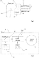
- FIG. 1 a tool system according to the invention comprising an electrically driven machine tool and a multi-purpose vacuum cleaner according to the invention is shown and generally denoted by the reference numeral 10.
- the machine tool 12 is designed as a hammer drill which can be activated and deactivated via a switch 12a and has a drilling tool 14 at one end for making bores on a workpiece 16.
- a multi-purpose vacuum cleaner 18 is provided, which has a telescopic tube 20.
- the multi-purpose vacuum cleaner 18 is designed to be particularly small in order to be attached directly to the machine tool 12.
- the multi-purpose vacuum cleaner 18 can also be a conventional, significantly larger vacuum cleaner, for example an industrial vacuum cleaner or household vacuum cleaner.
- the multi-purpose vacuum cleaner 18 shown has a telescopic tube 20 which is pretensioned in an extended position (for example by means of a spring, not shown).
- the telescopic tube 20 is compressed in a known manner by the workpiece 16 against the preload. The particles produced during drilling are sucked up via the telescopic tube as part of the multi-purpose vacuum cleaner 18.
- the multi-purpose vacuum cleaner 18 has a motor 22 which is used to produce the negative pressure required for suction.
- a control unit 24a is provided which receives a corresponding sensor signal from a sensor 26 and, based on this, the motor 22 controls.
- the sensor 26 and the control unit 24a are components of an activation mechanism 24 which enables the motor 22 to be activated and deactivated as a function of the operating state of the machine tool 12.
- the senor 26 can be part of the multi-purpose vacuum cleaner 18, for example it can be arranged in the telescopic tube 20, or the sensor 26 can alternatively be attached to the machine tool 12.
- the sensor 26 within the telescopic tube 20 can determine a displacement of the telescopic tube 20 when contact is made with the workpiece 16 and transmit a corresponding sensor signal for activating the motor 22 to the control unit 24a.
- a negative pressure occurring within the telescopic tube, a sound oscillation emitted by the machine tool 12, a vibration of the machine tool 12 or the multi-purpose vacuum cleaner attached to it can also be determined by sensors.
- the transmission of the sensor signal to the control unit 24a can take place wirelessly or via a wire or the like.
- an activation switch 28 for activating the activation mechanism 24 of the multi-purpose vacuum cleaner 18 is provided.
- the activation switch 28 is used to activate or deactivate the activation mechanism 24 before the start and after the completion of a work process.
- the control unit 24a can switch the motor 22 on and off as required based on a sensor signal from the sensor 26.
- the activation switch 28 is supplied with power via a battery 30.
- the battery 30 can also be replaced by an alternating current source
- the Multipurpose vacuum cleaner 18 can be connected to the AC power source in this case via an electrical cable.
- the activation switch 28 is switched on at the beginning of a complete work process and is only switched off again accordingly at the end. In between, the activation or deactivation and the switchover to the stand-by operating mode of the motor 22 takes place based on the sensor signal of the sensor 26.
- the activation mechanism according to the invention has the advantage over known solutions that, particularly in work processes in which the machine tool is repeatedly switched off briefly between individual work steps, for example when a series of bores is to be provided on a workpiece, the suction cup is also automatically deactivated or at least in one Stand-by mode is brought, in which it requires less electricity and causes less work noise. This significantly increases the working comfort for the user.
- connection of the multi-purpose vacuum cleaner to the machine tool also creates an electrical connection provided so that the machine tool and the multipurpose vacuum cleaner can be powered from the same power source.
- Multipurpose vacuum cleaner (18) according to one of the embodiments 1 to 3, wherein the multipurpose vacuum cleaner comprises a housing on which at least one receiving shaft is provided for securely receiving a battery that can be connected to the power supply.
- Multipurpose vacuum cleaner (18) according to one of the preceding embodiments, wherein the multipurpose vacuum cleaner has a housing with at least one receiving and / or fastening section, in or on which at least one powered machine tool and / or a holder for a charger for rechargeable batteries is securely received and / or can be releasably attached.
- Multipurpose vacuum cleaner (18) according to one of the preceding embodiments 2 to 5, wherein the sensor (26) of the activation mechanism (24) can be attached to the connected machine tool (12) and, depending on the position of the machine tool (12), of a change in position of the machine tool (12) or by a vibration caused by the machine tool (12) in the operating state or a change in pressure to switch the multi-purpose vacuum cleaner (18) on or off.
- Multipurpose vacuum cleaner (18) according to one of the preceding embodiments 2 to 5, wherein the multipurpose vacuum cleaner can be connected to the machine tool by means of its suction hose and the sensor of the multipurpose vacuum cleaner is attached within the suction hose and depending on a change in position of the suction hose, a change in pressure within the suction hose or from a vibration on the suction hose caused by the machine tool in the operating state causes the multi-purpose vacuum cleaner to be switched on or off.
- Multipurpose vacuum cleaner (18) according to one of the preceding embodiments 6 or 7, wherein the sensor (24) sends a wireless signal to a receiving unit of the control unit (24a) of the activation mechanism (24), which is processed by the control unit (24a) and based on the the control unit (24a) causes the power supply to supply the electric drive (22) of the multi-purpose vacuum cleaner (18) with power or not.
- Multipurpose vacuum cleaner (18) according to embodiment 8, a wire being provided in the suction hose which connects the sensor to a receiving unit the control unit of the activation mechanism, the sensor using this wire to send a signal to the receiving unit, which is processed by the control unit and based on which the control unit causes the power supply to supply the electric drive of the multi-purpose vacuum cleaner with power or not.
- Multipurpose vacuum cleaner (18) according to one of the preceding embodiments 2 to 9, wherein the activation mechanism (24) drives the electric drive ("2) of the multipurpose vacuum cleaner (18) in a mode with a reduced speed (standby Level) and a mode with a working speed (working level) is able to operate.
- Multipurpose vacuum cleaner (18) according to one of the preceding embodiments 2 to 10, wherein the activation mechanism (24) can be activated by means of an activation switch (28).
- Tool system (10) comprising a multi-purpose vacuum cleaner (18) according to embodiments 1 to 11 and an electrically driven machine tool (12) that can be connected to it.
Abstract
Die vorliegende Erfindung betrifft Werkzeugsystem (10) umfassend eine elektrisch angetriebene Werkzeugmaschine (12) sowie einen Mehrzweckstaubsauger (18), insbesondere zur Benutzung mit einer elektrisch angetriebenen Werkzeugmaschine (12), der einen elektrischen Antrieb (22) zum Antreiben einer Lüftereinheit, und eine Stromversorgung zum Zuführen von elektrischen Strom zu dem elektrischen Antrieb des Mehrzweckstaubsaugers (18) aufweist. Die Stromversorgung umfasst ein damit verbundenes elektrisches Kabel, das es einem Benutzer ermöglicht, die Stromversorgung fallweise mit einer Wechselstromquelle zu verbinden, sowie wenigstens eine mit der Stromversorgung verbindbare wiederaufladbare Batterie, die die Stromversorgung mit Gleichstrom versorgen vermag, so dass ein Benutzer den Mehrzweckstaubsauger (18) auch dann nutzen kann, wenn die Stromversorgung nicht über das elektrische Kabel mit einer Wechselstromquelle verbunden ist. Weiterhin weist die Stromversorgung ferner wenigstens einen elektrischen Anschluss auf, über den eine angetriebene Werkzeugmaschine mittels eines Kabels mit der Stromversorgung verbunden werden kann, so dass die Stromversorgung den elektrischen Strom sowohl dem elektrischen Antrieb des Mehrzweckstaubsaugers (18) als auch dem elektrischen Antrieb der verbundenen Werkzeugmaschine (12) zuzuführen vermag.The present invention relates to a tool system (10) comprising an electrically powered machine tool (12) and a multi-purpose vacuum cleaner (18), in particular for use with an electrically powered machine tool (12), an electric drive (22) for driving a fan unit, and a power supply for supplying electrical power to the electrical drive of the multi-purpose vacuum cleaner (18). The power supply comprises an electrical cable connected to it, which enables a user to connect the power supply to an AC power source on a case-by-case basis, as well as at least one rechargeable battery which can be connected to the power supply and which can supply the power supply with direct current so that a user can use the multi-purpose vacuum cleaner (18 ) can be used even when the power supply is not connected to an AC power source via the electrical cable. Furthermore, the power supply also has at least one electrical connection via which a driven machine tool can be connected to the power supply by means of a cable, so that the power supply supplies the electrical current to both the electrical drive of the multi-purpose vacuum cleaner (18) and the electrical drive of the connected machine tool (12) is able to supply.
Description
Die Erfindung betrifft einen Mehrzweckstaubsauger, insbesondere zur Benutzung mit einer elektrisch angetriebenen Werkzeugmaschine.The invention relates to a multi-purpose vacuum cleaner, in particular for use with an electrically powered machine tool.
Derartige Mehrzweckstaubsauger können dazu genutzt werden, sowohl nass als auch trocken zu saugen. Üblicherweise werden sie im Zusammenhang mit einer Werkzeugmaschine dazu genutzt, bei der Bearbeitung eines Werkstücks mit der Werkzeugmaschine anfallende Partikel, beispielsweise Bohrstaub und dergleichen, auf- oder abzusaugen, um die bei der Bearbeitung anfallende Verschmutzung möglichst gering zu halten.Such multi-purpose vacuum cleaners can be used to vacuum both wet and dry. Usually, in connection with a machine tool, they are used to suck up or suck off particles that arise when machining a workpiece with the machine tool, for example drilling dust and the like, in order to keep the contamination that arises during machining as low as possible.
Aus dem Stand der Technik sind unterschiedlichste Geräte dieser Art bekannt, die sowohl von Akkumulatoren (wiederaufladbaren Batterien) als auch über elektrische Kabel mit Strom versorgt werden können. Abhängig von der gewünschten Art der Anwendung eines solchen Mehrzweckstaubsaugers weisen die aus dem Stand der Technik bekannten Mehrzweckstaubsauger zusätzliche Merkmale auf, die aus Anwendersicht ihre Handhabung vereinfachen bzw. komfortabler gestalten sollen.A wide variety of devices of this type are known from the prior art, which can be supplied with power both from accumulators (rechargeable batteries) and via electrical cables. Depending on the desired type of use of such a multi-purpose vacuum cleaner, the multi-purpose vacuum cleaners known from the prior art have additional features which, from the user's point of view, are intended to simplify their handling or make them more comfortable.
So ist gemäß einem ersten Komfortaspekt ein mobiler Einsatz eines solchen Mehrzweckstaubsaugers wünschenswert. Entsprechend ist beispielsweise aus dem Dokument
Das Dokument
Weitere Hybridsauger, d. h. Staubsauger, die sowohl elektrisch betrieben als auch batteriebetrieben werden können, sind beispielsweise aus den Dokumenten
Ein weiterer Komfortaspekt, neben der mobilen Stromversorgung des Mehrzweckstaubsaugers, betrifft dessen Aktivierung. Grundsätzlich ist es aus dem Stand der Technik bekannt, einen Mehrzweckstaubsauger mit einer Werkzeugmaschine zu verbinden, wobei sowohl die Werkzeugmaschine als auch der Mehrzweckstaubsauger über jeweils einen separaten Ein-/Ausschalter verfügen. Der Anwender muss zum Ein- oder Ausschalten beider Geräte jedes der Geräte durch Betätigung des zugehörigen Schalters aktivieren bzw. deaktivieren.Another comfort aspect, in addition to the mobile power supply of the multi-purpose vacuum cleaner, concerns its activation. In principle, it is known from the prior art to connect a multi-purpose vacuum cleaner to a machine tool, with both the machine tool and the multi-purpose vacuum cleaner each having a separate on / off switch. Of the To switch both devices on or off, the user must activate or deactivate each of the devices by pressing the associated switch.
Daneben ist aus dem Dokument
Schließlich offenbart das Dokument
Zur weiteren Vereinfachung und Erhöhung des Komforts für einen Anwender bei der kombinierten Benutzung eines Mehrzweckstaubsaugers mit einer elektrisch angetriebenen Werkzeugmaschine schlägt die vorliegende Erfindung gemäß einem ersten Aspekt eine Ausgestaltung eines Mehrzweckstaubsaugers mit den Merkmalen des Anspruchs 1 vor.To further simplify and increase the convenience for a user when using a multipurpose vacuum cleaner with an electrically powered machine tool, the present invention proposes, according to a first aspect, an embodiment of a multipurpose vacuum cleaner with the features of claim 1.
Demgemäß weist die Stromversorgung des Mehrzweckstaubsaugers wenigstens einen elektrischen Anschluss auf, über den die angetriebene Werkzeugmaschine mittels eines Kabels mit der Stromversorgung verbunden werden kann, so dass die Stromversorgung des Mehrzweckstaubsaugers den elektrischen Strom sowohl dem elektrischen Antrieb des Mehrzweckstaubsaugers als auch dem elektrischen Antrieb der verbundenen Werkzeugmaschine zuzuführen vermag. Auf diese Weise ist es möglich, unabhängig davon, ob der Mehrzweckstaubsauger mittels einer Batterie oder über eine Wechselstromquelle mit Strom versorgt wird, auch die in Kombination mit dem Sauger nutzbare Werkzeugmaschine über die Stromversorgung des Mehrzweckstaubsaugers mit elektrischem Strom zu versorgen. Dies hat den Vorteil, dass insbesondere bei Baustellen, bei denen keine oder nur wenige Steckdosen zum Anschluss mit einer Wechselstromquelle verfügbar sind, der Mehrzwecksauger zugleich eine übliche Werkzeugmaschine mit Strom versorgen kann. Weiterhin kann der Mehrzweckstaubsauger selbst von einer wiederaufladbaren Batterie versorgt werden, wodurch eine vollkommene Unabhängigkeit von dem Vorhandensein einer Wechselstromquelle erreicht werden kann. Hierdurch werden der Komfort und die Mobilität der Maschinenkombination für den Anwender gegenüber bekannten Lösungen nennenswert erhöht.Accordingly, the power supply of the multi-purpose vacuum cleaner has at least one electrical connection via which the powered machine tool can be connected to the power supply by means of a cable, so that the power supply of the multi-purpose vacuum cleaner supplies the electrical current to both the electric drive of the multi-purpose vacuum cleaner and the electric drive of the connected machine tool able to supply. In this way it is possible, regardless of whether the multi-purpose vacuum cleaner is supplied with power by means of a battery or an alternating current source, also in combination to supply the machine tool that can be used with the vacuum cleaner with electrical power via the power supply of the multi-purpose vacuum cleaner. This has the advantage that, particularly on construction sites where no or only a few sockets are available for connection to an alternating current source, the multi-purpose vacuum cleaner can at the same time supply a conventional machine tool with power. Furthermore, the multi-purpose vacuum cleaner itself can be supplied by a rechargeable battery, whereby complete independence from the presence of an alternating current source can be achieved. This significantly increases the convenience and mobility of the machine combination for the user compared to known solutions.
Gemäß einem zweiten Aspekt der vorliegenden Erfindung wird ein Mehrzweckstaubsauger mit den Merkmalen des Anspruchs 2 vorgeschlagen.According to a second aspect of the present invention, a multi-purpose vacuum cleaner with the features of
Demgemäß umfasst die Stromversorgung des Mehrzweckstaubsaugers einen Aktivierungsmechanismus zum Ein- und Ausschalten des elektrischen Antriebs des Mehrzweckstaubsaugers, der geeignet ist, in Abhängigkeit von dem Betriebszustand einer mit dem Mehrzweckstaubsauger verbundenen elektrisch angetriebenen Werkzeugmaschine den elektrischen Antrieb des Mehrzweckstaubsaugers ein- oder auszuschalten, wobei der Aktivierungsmechanismus einen Sensor umfasst, der geeignet ist, den Betriebszustand der elektrisch angetriebenen Werkzeugmaschine zu detektieren, sowie eine Steuerungseinheit, die basierend auf dem detektierten Betriebszustand der Werkzeugmaschine den elektrischen Antrieb des Mehrzweckstaubsaugers ein- oder auszuschalten vermag.Accordingly, the power supply of the multi-purpose vacuum cleaner comprises an activation mechanism for switching the electric drive of the multi-purpose vacuum cleaner on and off, which is suitable for switching the electric drive of the multi-purpose vacuum cleaner on or off depending on the operating state of an electrically driven machine tool connected to the multi-purpose vacuum cleaner, the activation mechanism having a Includes sensor which is suitable for detecting the operating state of the electrically driven machine tool, as well as a control unit which is able to switch the electric drive of the multi-purpose vacuum cleaner on or off based on the detected operating state of the machine tool.
Im Unterschied zu bekannten Lösungen reicht es bei der vorliegenden Erfindung aus, wenn der Anwender die Werkzeugmaschine einschaltet, um auch eine Aktivierung des Mehrzweckstaubsaugers zu bewirken. Auch hierdurch wird wiederum der Komfort für den Anwender verbessert, da er nur einen Schalter zum Aktivieren und Deaktivieren beider Geräte betätigen muss. Ferner wird insbesondere bei längeren Arbeitsabläufen, z. B. beim Bohren von einer Vielzahl von Löchern, ein energieeffizienterer Betrieb des Mehrzweckstaubsaugers erreicht, da in der Regel der Anwender in solchen Fällen die aus dem Stand der Technik bekannten Lösungen zwischen den einzelnen Arbeitsgängen nicht ausschalten würde, die erfindungsgemäße Lösung jedoch eine automatische Abschaltung des Saugers bewirkt, wenn die Werkzeugmaschine ausgeschaltet wird. Desweiteren wird durch die vorgeschlagene Lösung der Erfindung der Arbeitslärm vermindert.In contrast to known solutions, with the present invention it is sufficient for the user to switch on the machine tool in order to also activate the multi-purpose vacuum cleaner. This, in turn, improves the convenience for the user, since he only has to operate one switch to activate and deactivate both devices. Furthermore, in particular longer work processes, e.g. B. when drilling a large number of holes, a more energy-efficient operation of the multi-purpose vacuum cleaner is achieved, since usually the user in such cases would not switch off the solutions known from the prior art between the individual work steps, but the solution according to the invention an automatic shutdown of the Sucker causes when the machine tool is turned off. Furthermore, the proposed solution of the invention reduces the work noise.
Selbstverständlich können die beiden Erfindungen gemäß dem ersten und dem zweiten Erfindungsaspekt zur weiteren Erhöhung des Komforts und der Mobilität einer Kombination eines Mehrzweckstaubsaugers mit einer elektrisch angetriebenen Werkzeugmaschine miteinander kombiniert werden.Of course, the two inventions according to the first and the second aspect of the invention can be combined with one another to further increase the comfort and mobility of a combination of a multi-purpose vacuum cleaner with an electrically driven machine tool.
Gemäß einer Weiterbildung der Erfindung kann die Stromversorgung wenigstens einen weiteren elektrischen Anschluss für wenigstens eine wiederaufladbare Batterie aufweisen, über den sie die elektrisch angeschlossene Batterie zu laden vermag. Der Ladevorgang einer derartigen wiederaufladbaren Batterie kann dabei auf einen Betriebszustand beschränkt sein, bei dem der Mehrzweckstaubsauger über ein elektrisches Kabel mit einer Wechselstromquelle verbunden ist. Alternativ oder zusätzlich kann jedoch die wiederaufladbare Batterie auch dann geladen werden, wenn der Mehrzweckstaubsauger selbst über eine Batterie betrieben wird bzw. nicht mit einer Wechselstromquelle, sondern nur mit einer weiteren Batterie verbunden ist. Der Ladevorgang kann ferner nicht, wie bei bekannten Lösungen, nur dann erfolgen, wenn sowohl der Mehrzwecksauger als auch eine gegebenenfalls damit elektrisch verbundene Werkzeugmaschine deaktiviert sind, d.h. keinen Strom benötigen. Stattdessen kann die Stromversorgung auch dann eine angeschlossene Batterie laden, wenn der Mehrzweckstaubsauger und gegebenenfalls eine damit verbundene Werkzeugmaschine in Betrieb sind. Hierzu kann die Stromversorgung des Mehrzweckstaubsaugers geeignet sein, zu ermitteln, ob bei einem aktivierten Mehrzwecksauger und ggf. einer damit elektrisch verbundene Werkzeugmaschine ebenfalls aktivierten Werkzeugmaschine die Stromquelle zusätzlich noch ausreichend Strom zur Verfügung stellt, um weiterhin auch eine angeschlossene wiederaufladbare Batterie zu laden.According to a further development of the invention, the power supply can have at least one further electrical connection for at least one rechargeable battery, via which it can charge the electrically connected battery. The charging process of such a rechargeable battery can be limited to an operating state in which the multi-purpose vacuum cleaner is connected to an alternating current source via an electrical cable. As an alternative or in addition, however, the rechargeable battery can also be charged when the multi-purpose vacuum cleaner itself is operated via a battery or is not connected to an alternating current source but only to another battery. Furthermore, as in the case of known solutions, the charging process cannot only take place when both the multi-purpose vacuum cleaner and a machine tool that may be electrically connected to it are deactivated, ie do not require any electricity. Instead, the power supply can also charge a connected battery when the multi-purpose vacuum cleaner and possibly a machine tool connected to it are in operation. For this purpose, the power supply of the multi-purpose vacuum cleaner can be suitable for determining whether an activated multi-purpose vacuum cleaner and possibly a machine tool electrically connected to it When the machine tool is also activated, the power source also provides sufficient power to continue charging a connected rechargeable battery.
Der Mehrzweckstaubsauger kann ferner ein Gehäuse umfassen, an dem wenigstens ein Aufnahmeschacht zur sicheren Aufnahme einer mit der Stromversorgung verbindbaren Batterie vorgesehen ist.The multi-purpose vacuum cleaner can furthermore comprise a housing on which at least one receiving shaft is provided for securely receiving a battery that can be connected to the power supply.
Alternativ oder zusätzlich kann der Mehrzweckstaubsauger ein Gehäuse mit wenigstens einem Aufnahme- und/oder Befestigungsabschnitt aufweisen, in bzw. an dem wenigstens eine angetriebene Werkzeugmaschine und/oder eine Halterung für ein Ladegerät für wiederaufladbare Batterien sicher aufgenommen und/oder lösbar befestigt werden kann bzw. können.Alternatively or additionally, the multi-purpose vacuum cleaner can have a housing with at least one receiving and / or fastening section, in or on which at least one powered machine tool and / or a holder for a charger for rechargeable batteries can be securely received and / or releasably fastened or can.
Bei einer derartigen Ausgestaltung dient das Gehäuse des Mehrzweckstaubsaugers nicht nur zur sicheren Aufnahme der innenliegenden Komponenten des Mehrzweckstaubsaugers, wie beispielsweise des Motors oder Lüfters, sondern auch zur Aufnahme und/oder Befestigung einer angetriebenen Werkzeugmaschine und/oder eines Ladegeräts für wiederaufladbare Batterien. Hierdurch wird ein besonders kompakter Aufbau für einen Anwender bereitgestellt, der den Transport des Mehrzweckstaubsaugers mit etwaigen Zubehörteilen, wie den vorstehend genannten, ermöglicht. Selbstverständlich können an dem Gehäuse auch weitere Aufnahme- und/oder Befestigungsabschnitte vorgesehen sein, die zur Aufnahme weiterer Zubehörteile, beispielsweise Werkzeuge der elektrisch angetriebenen Werkzeugmaschine und dergleichen, genutzt werden können.In such a configuration, the housing of the multi-purpose vacuum cleaner not only serves to securely accommodate the internal components of the multi-purpose vacuum cleaner, such as the motor or fan, but also to accommodate and / or attach a powered machine tool and / or a charger for rechargeable batteries. This provides a particularly compact design for a user, which enables the multi-purpose vacuum cleaner to be transported with any accessories, such as those mentioned above. Of course, further receiving and / or fastening sections can also be provided on the housing, which can be used to receive further accessories, for example tools of the electrically driven machine tool and the like.
Es kann ferner vorgesehen sein, dass der Sensor des Aktivierungsmechanismus an der verbundenen Werkzeugmaschine anbringbar ist und in Abhängigkeit von der Lage der Werkzeugmaschine, von einer Lageveränderung der Werkzeugmaschine oder von einer von der Werkzeugmaschine im Betriebszustand verursachten Schwingung oder einer Druckveränderung ein Ein- oder Ausschalten des Mehrzweckstaubsaugers veranlasst.It can further be provided that the sensor of the activation mechanism can be attached to the connected machine tool and depending on the position of the machine tool, a change in position of the machine tool or a change caused by the machine tool in the operating state Vibration or a change in pressure causes the multi-purpose vacuum cleaner to be switched on or off.
Der Begriff "Schwingungen" bezeichnet in diesem Zusammenhang alle Formen von Schwingungen, beispielsweise Vibrationen an der Werkzeugmaschine oder von der Werkzeugmaschine emittierte Schallschwingungen.In this context, the term “vibrations” denotes all forms of vibrations, for example vibrations on the machine tool or sound vibrations emitted by the machine tool.
So ist es beispielsweise denkbar, dass die Werkzeugmaschine einen Bohrhammer umfasst, an dem ein Lagesensor vorgesehen ist. Wird nun der Bohrhammer aufgenommen oder mit ihm hantiert, so können diese Bewegungen von dem Lagesensor detektiert werden. Das Sensorsignal, welches an die Steuerungseinheit weitergegeben wird, veranlasst die Steuerungseinheit wiederum dann, den Mehrzweckstaubsauger ein- bzw. auszuschalten.For example, it is conceivable that the machine tool comprises a hammer drill on which a position sensor is provided. If the hammer drill is now picked up or handled, these movements can be detected by the position sensor. The sensor signal, which is passed on to the control unit, then in turn causes the control unit to switch the multi-purpose vacuum cleaner on and off.
Alternativ oder zusätzlich zu einem Lagesensor kann selbstverständlich auch ein Beschleunigungssensor vorgesehen sein, der an der Werkzeugmaschine, beispielsweise einem Bohrhammer, angebracht ist. Ein solcher Beschleunigungssensor ist geeignet, an der Werkzeugmaschine auftretende Vibrationen zu detektieren und entsprechend ein Signal an die Steuerungseinheit weiterzugeben. Insbesondere bei der Ausgestaltung der Werkzeugmaschine als ein Bohrhammer bietet sich ein solcher Sensor an, da bei dieser Art von Werkzeugmaschinen massive Vibrationen durch das Schlagwerk entstehen, welche einfach von einem entsprechenden Sensor erfasst werden können.As an alternative or in addition to a position sensor, an acceleration sensor can of course also be provided, which is attached to the machine tool, for example a hammer drill. Such an acceleration sensor is suitable for detecting vibrations occurring on the machine tool and for transmitting a signal accordingly to the control unit. Such a sensor is particularly useful when the machine tool is designed as a hammer drill, since in this type of machine tool massive vibrations arise from the hammer mechanism, which can be easily detected by a corresponding sensor.
Alternativ oder zusätzlich kann der Sensor jedoch auch als Mikrofon ausgestaltet sein, das Motor- bzw. Arbeitsgeräusche der Werkzeugmaschine zu detektieren vermag. Ein solcher Sensor bietet sich insbesondere bei derartigen Werkzeugmaschinen an, bei deren Betrieb nennenswerte Arbeitsgeräusche aufkommen.As an alternative or in addition, however, the sensor can also be designed as a microphone that is able to detect engine or working noises of the machine tool. Such a sensor is particularly suitable for machine tools of this type, whose operation generates significant work noises.
Alternativ oder zusätzlich kann der Sensor auch als Drucksensor ausgestaltet sein, der geeignet ist, eine Druckveränderung zu detektieren. Beispielsweise kann die kombinierte elektrisch angetriebene Werkzeugmaschine einen Bohrhammer mit einem als Saugerteleskop ausgebildeten Mehrzweckstaubsauger umfassen. Sobald das Saugerteleskop eine Fläche des zu bearbeitenden Werkstücks berührt, entsteht innerhalb des Teleskops ein Unterdruck. Ein solcher Unterdruck kann von einem Drucksensors ermittelt werden, so dass dieser ein entsprechendes Signal an die Steuerungseinheit weiterzugeben vermag. Auch kann an dem Werkzeug selbst eine Druckveränderung mittels eines Sensors festgestellt werden, beispielsweise wenn das Werkzeug der elektrisch angetriebenen Werkzeugmaschine zur Bearbeitung eines Werkstücks mit diesem in Kontakt gebracht wird. Das Werkstück stellt dabei einen zu dem von dem Werkzeug aufgebrachten Druck bei der Bearbeitung entgegenwirkenden Druck bereit, der sich sensorisch ermitteln lässt.Alternatively or additionally, the sensor can also be designed as a pressure sensor which is suitable for detecting a change in pressure. For example, the combined electrically driven machine tool can comprise a hammer drill with a multi-purpose vacuum cleaner designed as a telescopic vacuum cleaner. As soon as the suction telescope touches a surface of the workpiece to be machined, a negative pressure is created inside the telescope. Such a negative pressure can be determined by a pressure sensor so that it can transmit a corresponding signal to the control unit. A change in pressure on the tool itself can also be determined by means of a sensor, for example when the tool of the electrically driven machine tool is brought into contact with a workpiece in order to machine it. The workpiece provides a pressure which counteracts the pressure applied by the tool during machining and which can be determined by sensors.
Alternativ oder zusätzlich kann sensorisch auch eine auf das Werkzeug wirkende Gegenkraft, beispielsweise der Widerstand des Werkstücks gegen die Bohrdrehung des Werkzeugs, ermittelt werdenAlternatively or additionally, a counterforce acting on the tool, for example the resistance of the workpiece to the drilling rotation of the tool, can also be determined by sensors
Je nach Ausgestaltung der Werkzeugmaschine kann alternativ oder zusätzlich zu einem solchen Drucksensor auch eine Aktivierung eines Mikroschalters vorgesehen sein, die durch einen Kontakt oder Widerstand des zu bearbeitenden Werkstücks mit dem Werkzeug oder einer zusätzlichen Komponente der Werkzeugmaschine, wie einem Teleskoprohr, betätigt wird.Depending on the configuration of the machine tool, an activation of a microswitch can be provided as an alternative or in addition to such a pressure sensor, which is actuated by a contact or resistance of the workpiece to be machined with the tool or an additional component of the machine tool, such as a telescopic tube.
Weiterhin kann zusätzlich oder alternativ auch eine Reflexlichtschranke zum Detektieren des Betriebszustands der elektrisch angetriebenen Werkzeugmaschine genutzt werden, die beispielsweise eine Relativbewegung des Werkzeugs bei Bearbeitung eines Werkstücks oder einer zusätzlichen Komponente, wie einem Teleskoprohr, detektiert und ein entsprechendes Signal an die Steuerungseinheit weiterzuleiten vermag.Furthermore, a reflex light barrier can additionally or alternatively be used to detect the operating state of the electrically driven machine tool, which for example detects a relative movement of the tool when machining a workpiece or an additional component, such as a telescopic tube, and is able to forward a corresponding signal to the control unit.
Das Sensorsignal kann alternativ auch von einem Sensor erzeugt werden, der die Leistungsversorgung der Werkzeugmaschine überwacht. So kann der Sensor auch an einer wiederaufladbaren Batterie der Werkzeugmaschine oder an dem Motor der Werkzeugmaschine angebracht sein und dann, wenn die Werkzeugmaschine aktiv mit Strom versorgt wird, ein entsprechendes Signal zur Aktivierung des Saugers abgeben.Alternatively, the sensor signal can also be generated by a sensor that monitors the power supply to the machine tool. Thus, the sensor can also be attached to a rechargeable battery of the machine tool or to the motor of the machine tool and then, when the machine tool is actively supplied with power, emit a corresponding signal to activate the suction device.
Gegebenenfalls kann der Sensor hierzu in einem Adapter vorgesehen sein, der zwischen der Werkzeugmaschine und ihrem Akkumulator angeordnet ist. Letztere Lösung ist vor allem dann von Vorteil, wenn eine Werkzeugmaschine zur Benutzung mit einem erfindungsgemäßen Mehrzweckstaubsauger nachgerüstet werden soll.For this purpose, the sensor can optionally be provided in an adapter which is arranged between the machine tool and its accumulator. The latter solution is particularly advantageous when a machine tool is to be retrofitted for use with a multi-purpose vacuum cleaner according to the invention.
Alternativ zu einem an der Werkzeugmaschine angebrachten Sensor kann der Mehrzweckstaubsauger mittels seines Absaugschlauchs mit der Werkzeugmaschine verbindbar sein und der Sensor des Mehrzweckstaubsaugers innerhalb des Absaugschlauchs angebracht sein und in Abhängigkeit von einer Lageveränderung des Absaugschlauchs, einer Druckveränderung innerhalb des Absaugschlauchs oder einer von der Werkzeugmaschine im Betriebszustand verursachten Schwingung am Absaugschlauch ein Ein- oder Ausschalten des Mehrzweckstaubsaugers veranlassen. Unter den Begriff "Schwingung" fällt beispielsweise, wie vorliegend auch, sowohl eine Vibration als auch eine Schallschwingung.As an alternative to a sensor attached to the machine tool, the multipurpose vacuum cleaner can be connected to the machine tool by means of its suction hose and the sensor of the multipurpose vacuum cleaner can be attached within the suction hose and depending on a change in position of the suction hose, a change in pressure within the suction hose or one of the machine tool in the operating state cause vibration on the suction hose to switch the multi-purpose vacuum cleaner on or off. The term “vibration” includes, for example, as in the present case, both a vibration and a sound vibration.
Unabhängig davon, wo der Sensor angebracht ist, kann dieser ein kabelloses Signal an eine Empfangseinheit der Steuerungseinheit des Aktivierungsmechanismus senden, das von der Steuerungseinheit verarbeitet wird und basierend auf dem die Steuerungseinheit die Stromversorgung dazu veranlasst, den elektrischen Antrieb des Mehrzweckstaubsaugers mit Strom zu versorgen oder nicht.Regardless of where the sensor is attached, it can send a wireless signal to a receiving unit of the control unit of the activation mechanism, which is processed by the control unit and based on which the control unit causes the power supply to supply the electric drive of the multi-purpose vacuum cleaner with power or Not.
Bei einer Ausgestaltung mit einem Absaugschlauch kann alternativ ein Draht in dem Absaugschlauch vorgesehen sein, der den Sensor mit einer Empfangseinheit der Steuerungseinheit des Aktivierungsmechanismus verbindet, wobei der Sensor über diesen Draht ein Signal an die Empfangseinheit sendet, das von der Steuerungseinheit verarbeitet wird und basierend auf dem die Steuerungseinheit die Stromversorgung dazu veranlasst, den elektrischen Antrieb des Mehrzweckstaubsaugers mit Strom zu versorgen oder nicht.In an embodiment with a suction hose, a wire can alternatively be provided in the suction hose which connects the sensor to a receiving unit of the control unit of the activation mechanism, the sensor sending a signal via this wire to the receiving unit, which is processed by the control unit and based on which the control unit causes the power supply to supply the electric drive of the multi-purpose vacuum cleaner with power or not.
Grundsätzlich können die beiden Alternativen, nämlich dass der Sensor ein kabelloses Signal sendet bzw. dass der Sensor über den Draht das Signal an eine Empfangseinheit sendet, nebeneinander vorgesehen sein, um die Zuverlässigkeit der Signalübertragung zu erhöhen.In principle, the two alternatives, namely that the sensor sends a wireless signal or that the sensor sends the signal to a receiving unit via the wire, can be provided side by side in order to increase the reliability of the signal transmission.
Bei einer Ausführungsform der Erfindung kann der Aktivierungsmechanismus den elektrischen Antrieb des Mehrzweckstaubsaugers abhängig von dem detektierten Betriebszustand der Werkzeugmaschine in einem Modus mit einer reduzierten Drehzahl und einem Modus mit einer Arbeitsdrehzahl betreiben. Bei dieser Ausgestaltung wird der Mehrzweckstaubsauger folglich nicht vollständig abgeschaltet, wenn die Werkzeugmaschine sich in einem inaktiven Betriebszustand befindet, sondern läuft mit einer geringen "Stand-by"-Drehzahl weiter. Auf diese Weise wird die Effizienz des Mehrzweckstaubsaugers erhöht, da dieser eine kürzere Anlaufphase zum Erreichen der Arbeitsdrehzahl des elektrischen Antriebs des Mehrzweckstaubsaugers benötigt.In one embodiment of the invention, the activation mechanism can operate the electric drive of the multi-purpose vacuum cleaner as a function of the detected operating state of the machine tool in a mode with a reduced speed and a mode with a working speed. In this embodiment, the multi-purpose vacuum cleaner is consequently not switched off completely when the machine tool is in an inactive operating state, but continues to run at a low “stand-by” speed. In this way, the efficiency of the multi-purpose vacuum cleaner is increased, since it requires a shorter start-up phase to reach the operating speed of the electric drive of the multi-purpose vacuum cleaner.
Dabei bezeichnet die Drehzahl in Zusammenhang mit dem elektrischen Antrieb des Mehrzweckstaubsaugers die Drehzahl des Lüfters zur Bereitstellung eines Unterdrucks, wie dieser üblicherweise bei Staubsaugern vorgesehen ist.The speed in connection with the electric drive of the multi-purpose vacuum cleaner designates the speed of the fan for providing a negative pressure, as is usually provided in vacuum cleaners.
Schließlich kann der Aktivierungsmechanismus mittels eines Aktivierungsschalters aktiviert werden. Der Anwender aktiviert folglich vor Beginn der gewünschten Benutzung des Aktivierungsmechanismus des Mehrzweckstaubsaugers, wonach dieser mit Hilfe der vorstehend beschriebenen Merkmale in Abhängigkeit von dem Betriebszustand der Werkzeugmaschine ein- bzw. ausgeschaltet werden kann. Wird der Mehrzweckstaubsauger nicht mehr benötigt, kann auch der Aktivierungsmechanismus ausgeschaltet werden.Finally, the activation mechanism can be activated by means of an activation switch. The user therefore activates before the start of the desired Use of the activation mechanism of the multi-purpose vacuum cleaner, after which it can be switched on or off with the aid of the features described above, depending on the operating state of the machine tool. If the multi-purpose vacuum cleaner is no longer required, the activation mechanism can also be switched off.
Die Erfindung umfasst schließlich auch ein Werkzeugsystem mit den Merkmalen des Anspruchs 12, das sowohl einen erfindungsgemäßen Mehrzweckstaubsauger als auch eine damit verbindbare elektrisch angetriebene Werkzeugmaschine umfasst.Finally, the invention also includes a tool system with the features of
Die weiteren Merkmale der Erfindung sind nachfolgend in den Ansprüchen und der Figurenbeschreibung unter Bezugnahme auf die beigefügten Figuren näher beschrieben. Die Figuren zeigen eine bevorzugte Ausführungsform der Erfindung, die mehrere Merkmale der Erfindung in Kombination miteinander aufweist. Selbstverständlich können diese jedoch auch einzeln und unabhängig voneinander bei der Erfindung Verwendung finden. Der Fachmann wird die beschriebenen Merkmale demgemäß auch einzeln betrachten und gegebenenfalls zu sinnvollen weiteren Unterkombinationen kombinieren können.The further features of the invention are described in more detail below in the claims and the description of the figures with reference to the accompanying figures. The figures show a preferred embodiment of the invention which has several features of the invention in combination with one another. Of course, however, these can also be used individually and independently of one another in the invention. The person skilled in the art will accordingly also consider the features described individually and, if necessary, combine them into further useful sub-combinations.
Es zeigten schematisch
-
Figur 1 einen erfindungsgemäßen Mehrzweckstaubsauger in Kombination mit einer elektrisch angetriebenen Werkzeugmaschine; -
Figur 2 -
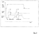
Figur 3 ein Diagramm, das die Signalabläufe über die Zeit darstellt.
-
Figure 1 a multi-purpose vacuum cleaner according to the invention in combination with an electrically powered machine tool; -
Figure 2 the schematic structure of the multi-purpose vacuum cleaner according to the invention; and -
Figure 3 a diagram showing the signal progression over time.
Die nachfolgenden
Die Werkzeugmaschine 12 ist vorliegend als ein Bohrhammer ausgebildet, der über einen Schalter 12a aktiviert und deaktiviert werden kann und an einem Ende ein Bohrwerkzeug 14 zum Anbringen von Bohrungen an einem Werkstück 16 aufweist. Weiterhin ist ein Mehrzweckstaubsauger 18 vorgesehen, der über ein Teleskoprohr 20 verfügt. Der Mehrzweckstaubsauger 18 ist in der dargestellten Ausführungsform besonders klein ausgebildet, um unmittelbar an der Werkzeugmaschine 12 angebracht zu werden. Selbstverständlich kann es sich aber bei dem Mehrzweckstaubsauger 18 auch um einen üblichen, deutlich größeren Staubsauger, zum Beispiel einen Industriestaubsauger oder Haushaltsstaubsauger, handeln.In the present case, the
Der dargestellte Mehrzweckstaubsauger 18 verfügt über ein Teleskoprohr 20, das in einer ausgefahrenen Stellung vorgespannt ist (beispielsweise über eine nicht dargestellte Feder). Bei einem weiteren Eindringen des Werkzeugs 14 in das Werkstück 16 wird das Teleskoprohr 20 in bekannter Weise von dem anliegenden Werkstück 16 gegen die Vorspannung zusammengedrückt. Über das Teleskoprohr als Teil des Mehrzweckstaubsaugers 18 werden die beim Bohren anfallenden Partikel aufgesaugt.The
In der
Der Sensor 26 kann wie in der gezeigten Darstellung Teil des Mehrzweckstaubsaugers 18 sein, beispielsweise kann dieser in dem Teleskoprohr 20 angeordnet sein, oder der Sensor 26 kann alternativ an der Werkzeugmaschine 12 angebracht sein. Vorliegend kann der Sensor 26 innerhalb des Teleskoprohrs 20 eine Verschiebung des Teleskoprohrs 20 bei Kontaktierung des Werkstücks 16 ermitteln und ein entsprechendes Sensorsignal zum Aktivieren des Motors 22 an die Steuerungseinheit 24a übertragen. Alternativ oder zusätzlich kann beispielsweise auch ein sich innerhalb des Teleskoprohrs einstellender Unterdruck, eine von der Werkzeugmaschine 12 emittierte Schallschwingung eine Vibration der Werkzeugmaschine 12 oder des daran angebrachten Mehrzweckstaubsaugers sensorisch ermittelt werden. Die Übertragung des Sensorsignals an die Steuerungseinheit 24a kann dabei kabellos oder über einen Draht oder dergleichen erfolgen.As in the illustration shown, the
Zusätzlich ist an dem Mehrzweckstaubsauger 18 gemäß der
Schließlich wird der Aktivierungsschalter 28 in der dargestellten Ausführungsform über eine Batterie 30 mit Leistung versorgt. Die Batterie 30 kann alternativ selbstverständlich auch durch eine Wechselstromquelle ersetzt werden, wobei der Mehrzweckstaubsauger 18 in diesem Fall über ein elektrisches Kabel mit der Wechselstromquelle verbindbar ist.Finally, in the embodiment shown, the
In der
An dem Diagramm kann man erkennen, dass der Aktivierungsschalter 28 zu Beginn eines vollständigen Arbeitsvorgangs eingeschaltet wird und erst zum Abschluss wieder entsprechend ausgeschaltet wird. Dazwischen erfolgt die Aktivierung bzw. Deaktivierung und das Umschalten in den Stand-by-Betriebsmodus des Motors 22 basierend auf dem Sensorsignal des Sensors 26.It can be seen from the diagram that the
Der erfindungsgemäße Aktivierungsmechanismus bringt gegenüber bekannten Lösungen den Vorteil, dass insbesondere bei Arbeitsvorgängen, bei denen die Werkzeugmaschine immer wieder zwischen einzelnen Arbeitsschritten kurz abgeschaltet wird, beispielsweise wenn eine Reihe von Bohrungen an einem Werkstück vorgesehen werden soll, der Sauger ebenfalls automatisch deaktiviert oder zumindest in einen Stand-by-Betriebszustand gebracht wird, in dem er weniger Strom benötigt und weniger Arbeitslärm verursacht. Hierdurch wird der Arbeitskomfort für den Anwender deutlich erhöht.The activation mechanism according to the invention has the advantage over known solutions that, particularly in work processes in which the machine tool is repeatedly switched off briefly between individual work steps, for example when a series of bores is to be provided on a workpiece, the suction cup is also automatically deactivated or at least in one Stand-by mode is brought, in which it requires less electricity and causes less work noise. This significantly increases the working comfort for the user.
Weiterhin wird durch die Verbindung des Mehrzweckstaubsaugers mit der Werkzeugmaschine erfindungsgemäß auch eine elektrische Verbindung bereitgestellt, so dass die Werkzeugmaschine und der Mehrzweckstaubsauger von derselben Stromquelle versorgt werden können.Furthermore, according to the invention, the connection of the multi-purpose vacuum cleaner to the machine tool also creates an electrical connection provided so that the machine tool and the multipurpose vacuum cleaner can be powered from the same power source.
Mehrzweckstaubsauger (18), insbesondere zur Benutzung mit einer elektrisch angetriebenen Werkzeugmaschine (12), der aufweist: einen elektrischen Antrieb (22) zum Antreiben einer Lüftereinheit, und eine Stromversorgung zum Zuführen von elektrischen Strom zu dem elektrischen Antrieb des Mehrzweckstaubsaugers, wobei die Stromversorgung ein damit verbundenes elektrisches Kabel umfasst, das es einem Benutzer ermöglicht, die Stromversorgung fallweise mit einer Wechselstromquelle zu verbinden, sowie wenigstens eine mit der Stromversorgung verbindbare wiederaufladbare Batterie, die die Stromversorgung mit Gleichstrom versorgen vermag, so dass ein Benutzer den Mehrzweckstaubsauger auch dann nutzen kann, wenn die Stromversorgung nicht über das elektrische Kabel mit einer Wechselstromquelle verbunden ist, wobei die Stromversorgung ferner wenigstens einen elektrischen Anschluss aufweist, über den eine angetriebene Werkzeugmaschine mittels eines Kabels mit der Stromversorgung verbunden werden kann, so dass die Stromversorgung den elektrischen Strom sowohl dem elektrischen Antrieb des Mehrzweckstaubsaugers als auch dem elektrischen Antrieb der verbundenen Werkzeugmaschine zuzuführen vermag.Multi-purpose vacuum cleaner (18), in particular for use with an electrically powered machine tool (12), which has: an electric drive (22) for driving a fan unit, and a power supply for supplying electrical power to the electric drive of the multi-purpose vacuum cleaner, the power supply being a electrical cable connected to it, which enables a user to connect the power supply to an alternating current source, as well as at least one rechargeable battery which can be connected to the power supply and which is able to supply the power supply with direct current so that a user can also use the multi-purpose vacuum cleaner if the power supply is not connected to an alternating current source via the electrical cable, wherein the power supply furthermore has at least one electrical connection via which a driven machine tool can be connected to the power supply by means of a cable, so that the power supply can supply the electrical current both to the electrical drive of the multi-purpose vacuum cleaner and to the electrical drive of the connected machine tool.
Mehrzweckstaubsauger (18), insbesondere zur Benutzung mit einer elektrisch angetriebenen Werkzeugmaschine (12), der aufweist: einen elektrischen Antrieb (22) zum Antreiben einer Lüftereinheit, und eine Stromversorgung zum Zuführen von elektrischen Strom zu dem elektrischen Antrieb des Mehrzweckstaubsaugers, wobei die Stromversorgung einen Aktivierungsmechanismus (24) zum Ein- und Ausschalten des elektrischen Antriebs(22) des Mehrzweckstaubsaugers (18) umfasst, der geeignet ist, in Abhängigkeit von dem Betriebszustand einer mit dem Mehrzweckstaubsauger (18) verbundenen elektrisch angetriebenen Werkzeugmaschine (12) den elektrischen Antrieb (22) des Mehrzweckstaubsaugers ein- oder auszuschalten, wobei der Aktivierungsmechanismus (24) einen Sensor (26) umfasst, der geeignet ist, den Betriebszustand der elektrisch angetriebenen Werkzeugmaschine (12) zu detektieren, sowie eine Steuerungseinheit (24a), die basierend auf dem detektierten Betriebszustand der Werkzeugmaschine (12) den elektrischen Antrieb (22) des Mehrzweckstaubsaugers (18) ein- oder auszuschalten vermag.Multi-purpose vacuum cleaner (18), in particular for use with an electrically powered machine tool (12), which has: an electric drive (22) for driving a fan unit, and a power supply for supplying electrical power to the electric drive of the multi-purpose vacuum cleaner, the power supply being a Activation mechanism (24) for switching the electric drive (22) of the multi-purpose vacuum cleaner (18) on and off which is suitable for switching the electric drive (22) of the multi-purpose vacuum cleaner on or off depending on the operating state of an electrically powered machine tool (12) connected to the multi-purpose vacuum cleaner (18), the activation mechanism (24) comprising a sensor (26) which is suitable for detecting the operating state of the electrically driven machine tool (12), as well as a control unit (24a) which, based on the detected operating state of the machine tool (12), switches the electric drive (22) of the multi-purpose vacuum cleaner (18) on or off able.
Mehrzweckstaubsauger (18) nach Ausführungsform 1 oder 2, wobei die Stromversorgung wenigstens einen weiteren elektrischen Anschluss für wenigstens eine wiederaufladbare Batterie aufweist, über den sie die elektrisch angeschlossene Batterie zu laden vermag.Multipurpose vacuum cleaner (18) according to
Mehrzweckstaubsauger (18) nach einer der Ausführungsformen 1 bis 3, wobei der Mehrzweckstaubsauger ein Gehäuse umfasst, an dem wenigstens ein Aufnahmeschacht zur sicheren Aufnahme einer mit der Stromversorgung verbindbaren Batterie vorgesehen ist.Multipurpose vacuum cleaner (18) according to one of the embodiments 1 to 3, wherein the multipurpose vacuum cleaner comprises a housing on which at least one receiving shaft is provided for securely receiving a battery that can be connected to the power supply.
Mehrzweckstaubsauger (18) nach einer der vorhergehenden Ausführungsformen, wobei der Mehrzweckstaubsauger ein Gehäuse mit wenigstens einem Aufnahme- und/oder Befestigungsabschnitt aufweist, in bzw. an dem wenigstens eine angetriebene Werkzeugmaschine und/oder eine Halterung für ein Ladegerät für wiederaufladbare Batterien sicher aufgenommen und/oder lösbar befestigt werden kann.Multipurpose vacuum cleaner (18) according to one of the preceding embodiments, wherein the multipurpose vacuum cleaner has a housing with at least one receiving and / or fastening section, in or on which at least one powered machine tool and / or a holder for a charger for rechargeable batteries is securely received and / or can be releasably attached.
Mehrzweckstaubsauger (18) nach einer der vorhergehenden Ausführungsformen 2 bis 5, wobei der Sensor (26) des Aktivierungsmechanismus (24) an der verbundenen Werkzeugmaschine (12) anbringbar ist und in Abhängigkeit von der Lage der Werkzeugmaschine (12), von einer Lageveränderung der Werkzeugmaschine (12) oder von einer von der Werkzeugmaschine (12) im Betriebszustand verursachten Schwingung oder einer Druckveränderung ein- oder Ausschalten des Mehrzweckstaubsaugers (18) veranlasst.Multipurpose vacuum cleaner (18) according to one of the preceding
Mehrzweckstaubsauger (18) nach einer der vorhergehenden Ausführungsformen 2 bis 5, wobei der Mehrzweckstaubsauger mittels seines Absaugschlauchs mit der Werkzeugmaschine verbindbar ist und der Sensor des Mehrzweckstaubsaugers innerhalb des Absaugschlauchs angebracht ist und in Abhängigkeit von einer Lageveränderung des Absaugschlauchs, einer Druckveränderung innerhalb des Absaugschlauchs oder von einer von der Werkzeugmaschine im Betriebszustand verursachten Schwingung am Absaugschlauch ein Ein- oder Ausschaltern des Mehrzweckstaubsaugers veranlasst.Multipurpose vacuum cleaner (18) according to one of the preceding
Mehrzweckstaubsauger (18) nach einer der vorhergehenden Ausführungsformen 6 oder 7, wobei der Sensor (24) ein kabelloses Signal an eine Empfangseinheit der Steuerungseinheit (24a) des Aktivierungsmechanismus (24) sendet, das von der Steuerungseinheit (24a) verarbeitet wird und basierend auf dem die Steuerungseinheit (24a) die Stromversorgung dazu veranlasst, den elektrischen Antrieb (22) des Mehrzweckstaubsaugers (18) mit Strom zu versorgen oder nicht.Multipurpose vacuum cleaner (18) according to one of the preceding embodiments 6 or 7, wherein the sensor (24) sends a wireless signal to a receiving unit of the control unit (24a) of the activation mechanism (24), which is processed by the control unit (24a) and based on the the control unit (24a) causes the power supply to supply the electric drive (22) of the multi-purpose vacuum cleaner (18) with power or not.
Mehrzweckstaubsauger (18) nach der Ausführungsform 8, wobei in dem Absaugschlauch ein Draht vorgesehen ist, der den Sensor mit einer Empfangseinheit der Steuerungseinheit des Aktivierungsmechanismus verbindet, wobei der Sensor über diesen Draht ein Signal an die Empfangseinheit sendet, das von der Steuerungseinheit verarbeitet wird und basierend auf dem die Steuerungseinheit die Stromversorgung dazu veranlasst, den elektrischen Antrieb des Mehrzweckstaubsaugers mit Strom zu versorgen oder nicht.Multipurpose vacuum cleaner (18) according to embodiment 8, a wire being provided in the suction hose which connects the sensor to a receiving unit the control unit of the activation mechanism, the sensor using this wire to send a signal to the receiving unit, which is processed by the control unit and based on which the control unit causes the power supply to supply the electric drive of the multi-purpose vacuum cleaner with power or not.
Mehrzweckstaubsauger (18) nach einer der vorhergehenden Ausführungsformen 2 bis 9, wobei der Aktivierungsmechanismus (24) den elektrischen Antrieb ("2) des Mehrzweckstaubsaugers (18) abhängig von dem detektierten Betriebszustand der Werkzeugmaschine (12) in einem Modus mit einer reduzierten Drehzahl (Standby Level)und einem Modus mit einer Arbeitsdrehzahl (Working Level) zu betreiben vermag.Multipurpose vacuum cleaner (18) according to one of the preceding
Mehrzweckstaubsauger (18) nach einer der vorhergehenden Ausführungsformen 2 bis 10, wobei der Aktivierungsmechanismus (24) mittels eines Aktivierungsschalter (28) aktiviert werden kann.Multipurpose vacuum cleaner (18) according to one of the preceding
Werkzeugsystem (10) umfassend einen Mehrzweckstaubsauger (18) gemäß den Ausführungsformen 1 bis 11 sowie eine damit verbindbare elektrisch angetriebene Werkzeugmaschine (12).Tool system (10) comprising a multi-purpose vacuum cleaner (18) according to embodiments 1 to 11 and an electrically driven machine tool (12) that can be connected to it.
Claims (9)
wobei die Stromversorgung einen Aktivierungsmechanismus (24) zum Ein- und Ausschalten des elektrischen Antriebs(22) des Mehrzweckstaubsaugers (18) umfasst, der geeignet ist, in Abhängigkeit von dem Betriebszustand einer mit dem Mehrzweckstaubsauger (18) verbundenen elektrisch angetriebenen Werkzeugmaschine (12) den elektrischen Antrieb (22) des Mehrzweckstaubsaugers ein- oder auszuschalten,
wobei der Aktivierungsmechanismus (24) einen Sensor (26) umfasst, der geeignet ist, den Betriebszustand der elektrisch angetriebenen Werkzeugmaschine (12) zu detektieren, sowie eine Steuerungseinheit (24a), die basierend auf dem detektierten Betriebszustand der Werkzeugmaschine (12) den elektrischen Antrieb (22) des Mehrzweckstaubsaugers (18) ein- oder auszuschalten vermag,
wobei der Sensor (26) des Aktivierungsmechanismus (24) an der verbundenen Werkzeugmaschine (12) anbringbar ist und in Abhängigkeit von der Lage der Werkzeugmaschine (12), von einer Lageveränderung der Werkzeugmaschine (12) oder von einer von der Werkzeugmaschine (12) im Betriebszustand verursachten Schwingung oder einer Druckveränderung ein- oder Ausschalten des Mehrzweckstaubsaugers (18) veranlasst.
wherein the power supply comprises an activation mechanism (24) for switching the electric drive (22) of the multi-purpose vacuum cleaner (18) on and off, which is suitable depending on the operating state of an electrically powered machine tool (12) connected to the multi-purpose vacuum cleaner (18) to switch the electric drive (22) of the multi-purpose vacuum cleaner on or off,
wherein the activation mechanism (24) comprises a sensor (26) which is suitable for detecting the operating state of the electrically driven machine tool (12), as well as a control unit (24a) which based on the detected operating state of the machine tool (12) the electric drive (22) is able to switch the multi-purpose vacuum cleaner (18) on or off,
wherein the sensor (26) of the activation mechanism (24) can be attached to the connected machine tool (12) and depending on the position of the machine tool (12), a change in position of the machine tool (12) or one of the machine tool (12) in the Operating state caused vibration or a change in pressure on or off the multi-purpose vacuum cleaner (18) caused.
wobei die Stromversorgung einen Aktivierungsmechanismus (24) zum Ein- und Ausschalten des elektrischen Antriebs(22) des Mehrzweckstaubsaugers (18) umfasst, der geeignet ist, in Abhängigkeit von dem Betriebszustand einer mit dem Mehrzweckstaubsauger (18) verbundenen elektrisch angetriebenen Werkzeugmaschine (12) den elektrischen Antrieb (22) des Mehrzweckstaubsaugers ein- oder auszuschalten,
wobei der Aktivierungsmechanismus (24) einen Sensor (26) umfasst, der geeignet ist, den Betriebszustand der elektrisch angetriebenen Werkzeugmaschine (12) zu detektieren, sowie eine Steuerungseinheit (24a), die basierend auf dem detektierten Betriebszustand der Werkzeugmaschine (12) den elektrischen Antrieb (22) des Mehrzweckstaubsaugers (18) ein- oder auszuschalten vermag,
wobei der Mehrzweckstaubsauger mittels seines Absaugschlauchs mit der Werkzeugmaschine verbindbar ist und der Sensor (26) des Mehrzweckstaubsaugers innerhalb des Absaugschlauchs angebracht ist und in Abhängigkeit von einer Lageveränderung des Absaugschlauchs, einer Druckveränderung innerhalb des Absaugschlauchs oder von einer von der Werkzeugmaschine im Betriebszustand verursachten Schwingung am Absaugschlauch ein Ein- oder Ausschaltern des Mehrzweckstaubsaugers veranlasst.
wherein the power supply comprises an activation mechanism (24) for switching the electric drive (22) of the multi-purpose vacuum cleaner (18) on and off, which is suitable depending on the operating state of an electrically powered machine tool (12) connected to the multi-purpose vacuum cleaner (18) to switch the electric drive (22) of the multi-purpose vacuum cleaner on or off,
wherein the activation mechanism (24) comprises a sensor (26) which is suitable for detecting the operating state of the electrically driven machine tool (12), as well as a control unit (24a) which based on the detected operating state of the machine tool (12) the electric drive (22) is able to switch the multi-purpose vacuum cleaner (18) on or off,
The multi-purpose vacuum cleaner can be connected to the machine tool by means of its suction hose and the sensor (26) of the multi-purpose vacuum cleaner is attached within the suction hose and depending on a change in position of the suction hose, a change in pressure within the suction hose or a vibration on the suction hose caused by the machine tool in the operating state causes the multi-purpose vacuum cleaner to be switched on or off.
wobei die Stromversorgung wenigstens einen weiteren elektrischen Anschluss für wenigstens eine wiederaufladbare Batterie aufweist, über den sie die elektrisch angeschlossene Batterie zu laden vermag.Tool system (10) according to claim 1 or 2,
wherein the power supply has at least one further electrical connection for at least one rechargeable battery, via which it is able to charge the electrically connected battery.
wobei der Mehrzweckstaubsauger ein Gehäuse umfasst, an dem wenigstens ein Aufnahmeschacht zur sicheren Aufnahme einer mit der Stromversorgung verbindbaren Batterie vorgesehen ist.Tool system (10) according to one of Claims 1 to 3,
wherein the multi-purpose vacuum cleaner comprises a housing on which at least one receiving shaft is provided for securely receiving a battery that can be connected to the power supply.
wobei der Mehrzweckstaubsauger ein Gehäuse mit wenigstens einem Aufnahme- und/oder Befestigungsabschnitt aufweist, in bzw. an dem wenigstens eine angetriebene Werkzeugmaschine und/oder eine Halterung für ein Ladegerät für wiederaufladbare Batterien sicher aufgenommen und/oder lösbar befestigt werden kann.Tool system (10) according to one of the preceding claims,
wherein the multi-purpose vacuum cleaner has a housing with at least one receiving and / or fastening section, in or on which at least one powered machine tool and / or a holder for a charger for rechargeable batteries can be safely received and / or releasably fastened.
wobei der Sensor (24) ein kabelloses Signal an eine Empfangseinheit der Steuerungseinheit (24a) des Aktivierungsmechanismus (24) sendet, das von der Steuerungseinheit (24a) verarbeitet wird und basierend auf dem die Steuerungseinheit (24a) die Stromversorgung dazu veranlasst, den elektrischen Antrieb (22) des Mehrzweckstaubsaugers (18) mit Strom zu versorgen oder nicht.Tool system (10) according to one of the preceding claims,
wherein the sensor (24) sends a wireless signal to a receiving unit of the control unit (24a) of the activation mechanism (24), which is processed by the control unit (24a) and based on which the control unit (24a) causes the power supply to activate the electric drive (22) of the multi-purpose vacuum cleaner (18) to be supplied with power or not.
wobei in dem Absaugschlauch ein Draht vorgesehen ist, der den Sensor mit einer Empfangseinheit der Steuerungseinheit des Aktivierungsmechanismus verbindet, wobei der Sensor über diesen Draht ein Signal an die Empfangseinheit sendet, das von der Steuerungseinheit verarbeitet wird und basierend auf dem die Steuerungseinheit die Stromversorgung dazu veranlasst, den elektrischen Antrieb des Mehrzweckstaubsaugers mit Strom zu versorgen oder nicht.Tool system (10) according to claim 2,
wherein a wire is provided in the suction hose which connects the sensor with a receiving unit of the control unit of the activation mechanism, the sensor sending a signal via this wire to the receiving unit, which is processed by the control unit and based on which the control unit causes the power supply to do so whether or not to power the electric drive of the multi-purpose vacuum cleaner.
wobei der Aktivierungsmechanismus (24) den elektrischen Antrieb (22) des Mehrzweckstaubsaugers (18) abhängig von dem detektierten Betriebszustand der Werkzeugmaschine (12) in einem Modus mit einer reduzierten Drehzahl (Standby Level)und einem Modus mit einer Arbeitsdrehzahl (Working Level) zu betreiben vermag.Tool system (10) according to one of the preceding claims,
wherein the activation mechanism (24) to operate the electric drive (22) of the multi-purpose vacuum cleaner (18) depending on the detected operating state of the machine tool (12) in a mode with a reduced speed (standby level) and a mode with a working speed (working level) able.
wobei der Aktivierungsmechanismus (24) mittels eines Aktivierungsschalter (28) aktiviert werden kann.Tool system (10) according to one of the preceding claims,
wherein the activation mechanism (24) can be activated by means of an activation switch (28).
Applications Claiming Priority (2)
| Application Number | Priority Date | Filing Date | Title |
|---|---|---|---|
| DE201310018278 DE102013018278A1 (en) | 2013-10-31 | 2013-10-31 | Multi-purpose vacuum cleaners |
| EP14184083.5A EP2878249B1 (en) | 2013-10-31 | 2014-09-09 | Multipurpose vacuum cleaner |
Related Parent Applications (2)
| Application Number | Title | Priority Date | Filing Date |
|---|---|---|---|
| EP14184083.5A Division EP2878249B1 (en) | 2013-10-31 | 2014-09-09 | Multipurpose vacuum cleaner |
| EP14184083.5A Division-Into EP2878249B1 (en) | 2013-10-31 | 2014-09-09 | Multipurpose vacuum cleaner |
Publications (1)
| Publication Number | Publication Date |
|---|---|
| EP3788921A1 true EP3788921A1 (en) | 2021-03-10 |
Family
ID=51492252
Family Applications (2)
| Application Number | Title | Priority Date | Filing Date |
|---|---|---|---|
| EP20195645.5A Withdrawn EP3788921A1 (en) | 2013-10-31 | 2014-09-09 | Multipurpose vacuum cleaner |
| EP14184083.5A Active EP2878249B1 (en) | 2013-10-31 | 2014-09-09 | Multipurpose vacuum cleaner |
Family Applications After (1)
| Application Number | Title | Priority Date | Filing Date |
|---|---|---|---|
| EP14184083.5A Active EP2878249B1 (en) | 2013-10-31 | 2014-09-09 | Multipurpose vacuum cleaner |
Country Status (2)
| Country | Link |
|---|---|
| EP (2) | EP3788921A1 (en) |
| DE (1) | DE102013018278A1 (en) |
Families Citing this family (13)
| Publication number | Priority date | Publication date | Assignee | Title |
|---|---|---|---|---|
| US9055033B2 (en) | 2012-07-17 | 2015-06-09 | Milwaukee Electric Tool Corporation | Universal protocol for power tools |
| DE102016108941A1 (en) | 2016-05-13 | 2017-11-16 | Vorwerk & Co. Interholding Gesellschaft mit beschränkter Haftung | Hand tool and method for operating a hand tool |
| DE102017100541A1 (en) | 2017-01-12 | 2018-07-12 | Metabowerke Gmbh | Multi-purpose vacuum cleaners |
| EP3648648A4 (en) | 2017-07-05 | 2021-03-31 | Milwaukee Electric Tool Corporation | Adapters for communication between power tools |
| DE202017104107U1 (en) | 2017-07-10 | 2017-07-30 | Metabowerke Gmbh | Use of a suction hose for user control |
| DE102017115436A1 (en) | 2017-07-10 | 2019-01-10 | Metabowerke Gmbh | Method for user control of a multipurpose vacuum cleaner |
| CN207887571U (en) * | 2017-11-10 | 2018-09-21 | 常州格力博有限公司 | The jetting machine of AC and DC |
| DE102018102982A1 (en) | 2018-02-09 | 2019-08-14 | Metabowerke Gmbh | Charger and method for charging a battery pack |
| US11011053B2 (en) | 2018-07-31 | 2021-05-18 | Tti (Macao Commercial Offshore) Limited | Systems and methods for remote power tool device control |
| DE102018124324B3 (en) * | 2018-10-02 | 2020-02-27 | Metabowerke Gmbh | Machine tool system with replacement load |
| EP3883727A4 (en) | 2018-11-19 | 2023-03-15 | Milwaukee Electric Tool Corporation | Dust collector including filter cleaning mechanism |
| DE102020200483A1 (en) | 2020-01-16 | 2021-07-22 | Robert Bosch Gesellschaft mit beschränkter Haftung | Method for controlling a suction device |
| CN219665906U (en) | 2020-03-25 | 2023-09-12 | 米沃奇电动工具公司 | Dust collector for use with a hand-held power tool |
Citations (11)
| Publication number | Priority date | Publication date | Assignee | Title |
|---|---|---|---|---|
| US5709007A (en) | 1996-06-10 | 1998-01-20 | Chiang; Wayne | Remote control vacuum cleaner |
| DE19902130A1 (en) | 1998-01-23 | 1999-09-23 | Kwang Ju Electronics Co Ltd | Remote control device of a vacuum cleaner |
| US6448732B1 (en) | 1999-08-10 | 2002-09-10 | Pacific Steamex Cleaning Systems, Inc. | Dual mode portable suction cleaner |
| EP1240976A1 (en) * | 2001-03-14 | 2002-09-18 | HILTI Aktiengesellschaft | Suction module |
| US20040088817A1 (en) * | 2002-11-12 | 2004-05-13 | Cochran John R. | AC/DC hand portable wet/dry vacuum having improved portability and convenience |
| US20080284363A1 (en) | 2006-10-17 | 2008-11-20 | Lucas Delbert E | Hybrid electric cleaning device |
| US20090083932A1 (en) | 2007-10-01 | 2009-04-02 | Brandon Henderson | Electrically and battery powered vacuum cleaner |
| US20090241283A1 (en) * | 2008-01-21 | 2009-10-01 | Michael Loveless | Tool operated switch for vacuums |
| US20100199453A1 (en) * | 2009-02-09 | 2010-08-12 | Brotto Daniele C | Wireless particle collection system |
| EP2433543A2 (en) * | 2010-09-27 | 2012-03-28 | Makita Corporation | Dust Collector |
| DE102012003073A1 (en) * | 2012-02-17 | 2013-08-22 | Festool Group Gmbh & Co. Kg | Suction device for separating particle in suction flow from handheld machine tool, has suction communication device with suction channel to transmit leadless control signal and alarm signal to external communication device of hand tool |
Family Cites Families (5)
| Publication number | Priority date | Publication date | Assignee | Title |
|---|---|---|---|---|
| JPH03168117A (en) * | 1989-11-28 | 1991-07-19 | Tokyo Electric Co Ltd | Vacuum cleaner |
| JP3061919B2 (en) * | 1991-01-31 | 2000-07-10 | 三菱電機ホーム機器株式会社 | Drive control device for vacuum cleaner |
| DE10134062A1 (en) * | 2001-07-13 | 2003-01-30 | Alto Deutschland Gmbh | Device for sucking up dirt/trash has electrically operated turbine and pneumatic switch-on sequence of automatic operations run by external pneumatic tool |
| DE102008054489A1 (en) * | 2008-12-10 | 2010-06-17 | Hilti Aktiengesellschaft | Tooling system |
| DE102010040336A1 (en) * | 2010-09-07 | 2012-03-08 | Alfred Kärcher Gmbh & Co. Kg | Device and method for detecting a change in operating state of a power tool and vacuum cleaner |
-
2013
- 2013-10-31 DE DE201310018278 patent/DE102013018278A1/en not_active Ceased
-
2014
- 2014-09-09 EP EP20195645.5A patent/EP3788921A1/en not_active Withdrawn
- 2014-09-09 EP EP14184083.5A patent/EP2878249B1/en active Active
Patent Citations (13)
| Publication number | Priority date | Publication date | Assignee | Title |
|---|---|---|---|---|
| US5709007A (en) | 1996-06-10 | 1998-01-20 | Chiang; Wayne | Remote control vacuum cleaner |
| DE19902130A1 (en) | 1998-01-23 | 1999-09-23 | Kwang Ju Electronics Co Ltd | Remote control device of a vacuum cleaner |
| US6448732B1 (en) | 1999-08-10 | 2002-09-10 | Pacific Steamex Cleaning Systems, Inc. | Dual mode portable suction cleaner |
| EP1240976A1 (en) * | 2001-03-14 | 2002-09-18 | HILTI Aktiengesellschaft | Suction module |
| US7653963B2 (en) | 2002-11-12 | 2010-02-02 | Black & Decker Inc. | AC/DC hand portable wet/dry vacuum having improved portability and convenience |
| EP1419723B1 (en) | 2002-11-12 | 2009-06-17 | Black & Decker Inc. | AC/DC hand portable wet/dry vacuum having improved portability and convenience |
| US20040088817A1 (en) * | 2002-11-12 | 2004-05-13 | Cochran John R. | AC/DC hand portable wet/dry vacuum having improved portability and convenience |
| US20080284363A1 (en) | 2006-10-17 | 2008-11-20 | Lucas Delbert E | Hybrid electric cleaning device |
| US20090083932A1 (en) | 2007-10-01 | 2009-04-02 | Brandon Henderson | Electrically and battery powered vacuum cleaner |
| US20090241283A1 (en) * | 2008-01-21 | 2009-10-01 | Michael Loveless | Tool operated switch for vacuums |
| US20100199453A1 (en) * | 2009-02-09 | 2010-08-12 | Brotto Daniele C | Wireless particle collection system |
| EP2433543A2 (en) * | 2010-09-27 | 2012-03-28 | Makita Corporation | Dust Collector |
| DE102012003073A1 (en) * | 2012-02-17 | 2013-08-22 | Festool Group Gmbh & Co. Kg | Suction device for separating particle in suction flow from handheld machine tool, has suction communication device with suction channel to transmit leadless control signal and alarm signal to external communication device of hand tool |
Also Published As
| Publication number | Publication date |
|---|---|
| DE102013018278A1 (en) | 2015-04-30 |
| EP2878249B1 (en) | 2021-11-17 |
| EP2878249A1 (en) | 2015-06-03 |
Similar Documents
| Publication | Publication Date | Title |
|---|---|---|
| EP2878249B1 (en) | Multipurpose vacuum cleaner | |
| EP2628431B2 (en) | Identification method for a suction device and a hand machine tool | |
| EP3545805B1 (en) | Suction device with a suction device transmitter and external communication device for same | |
| EP2628428B1 (en) | Suction device with a charging device | |
| EP2613683B1 (en) | Device and method for sensing a change in operating state of a power tool, and vacuum cleaner | |
| DE102013222313A1 (en) | device system | |
| EP3599961A1 (en) | Vacuum apparatus having a plug-in module | |
| DE102017218852A1 (en) | Absauganschlussadapter | |
| DE102012003073A1 (en) | Suction device for separating particle in suction flow from handheld machine tool, has suction communication device with suction channel to transmit leadless control signal and alarm signal to external communication device of hand tool | |
| DE102016113579A1 (en) | Adapter assembly system | |
| EP2196282B1 (en) | Tool system | |
| DE202017104107U1 (en) | Use of a suction hose for user control | |
| DE102019107870A1 (en) | dust collectors | |
| WO2019063292A1 (en) | Suction apparatus | |
| DE102017100541A1 (en) | Multi-purpose vacuum cleaners | |
| EP3813622B1 (en) | System of suction device and hand tool and method of operating the system | |
| DE102017115436A1 (en) | Method for user control of a multipurpose vacuum cleaner | |
| DE102018124324B3 (en) | Machine tool system with replacement load | |
| WO2020126728A1 (en) | Rechargeable device having an electromechanical interface for a replaceable drive unit |
Legal Events
| Date | Code | Title | Description |
|---|---|---|---|
| PUAI | Public reference made under article 153(3) epc to a published international application that has entered the european phase |
Free format text: ORIGINAL CODE: 0009012 |
|
| STAA | Information on the status of an ep patent application or granted ep patent |
Free format text: STATUS: THE APPLICATION HAS BEEN PUBLISHED |
|
| AC | Divisional application: reference to earlier application |
Ref document number: 2878249 Country of ref document: EP Kind code of ref document: P |
|
| AK | Designated contracting states |
Kind code of ref document: A1 Designated state(s): AL AT BE BG CH CY CZ DE DK EE ES FI FR GB GR HR HU IE IS IT LI LT LU LV MC MK MT NL NO PL PT RO RS SE SI SK SM TR |
|
| STAA | Information on the status of an ep patent application or granted ep patent |
Free format text: STATUS: THE APPLICATION IS DEEMED TO BE WITHDRAWN |
|
| 18D | Application deemed to be withdrawn |
Effective date: 20210911 |