EP3788338B1 - Measurement of elastic modulus of moving web - Google Patents
Measurement of elastic modulus of moving web Download PDFInfo
- Publication number
- EP3788338B1 EP3788338B1 EP19796814.2A EP19796814A EP3788338B1 EP 3788338 B1 EP3788338 B1 EP 3788338B1 EP 19796814 A EP19796814 A EP 19796814A EP 3788338 B1 EP3788338 B1 EP 3788338B1
- Authority
- EP
- European Patent Office
- Prior art keywords
- paper web
- cardboard
- measurement
- web
- elastic modulus
- Prior art date
- Legal status (The legal status is an assumption and is not a legal conclusion. Google has not performed a legal analysis and makes no representation as to the accuracy of the status listed.)
- Active
Links
Images


Classifications
-
- G—PHYSICS
- G01—MEASURING; TESTING
- G01L—MEASURING FORCE, STRESS, TORQUE, WORK, MECHANICAL POWER, MECHANICAL EFFICIENCY, OR FLUID PRESSURE
- G01L5/00—Apparatus for, or methods of, measuring force, work, mechanical power, or torque, specially adapted for specific purposes
- G01L5/04—Apparatus for, or methods of, measuring force, work, mechanical power, or torque, specially adapted for specific purposes for measuring tension in flexible members, e.g. ropes, cables, wires, threads, belts or bands
- G01L5/08—Apparatus for, or methods of, measuring force, work, mechanical power, or torque, specially adapted for specific purposes for measuring tension in flexible members, e.g. ropes, cables, wires, threads, belts or bands using fluid means
-
- G—PHYSICS
- G01—MEASURING; TESTING
- G01B—MEASURING LENGTH, THICKNESS OR SIMILAR LINEAR DIMENSIONS; MEASURING ANGLES; MEASURING AREAS; MEASURING IRREGULARITIES OF SURFACES OR CONTOURS
- G01B11/00—Measuring arrangements characterised by the use of optical techniques
- G01B11/16—Measuring arrangements characterised by the use of optical techniques for measuring the deformation in a solid, e.g. optical strain gauge
-
- G—PHYSICS
- G01—MEASURING; TESTING
- G01N—INVESTIGATING OR ANALYSING MATERIALS BY DETERMINING THEIR CHEMICAL OR PHYSICAL PROPERTIES
- G01N3/00—Investigating strength properties of solid materials by application of mechanical stress
- G01N3/20—Investigating strength properties of solid materials by application of mechanical stress by applying steady bending forces
-
- B—PERFORMING OPERATIONS; TRANSPORTING
- B65—CONVEYING; PACKING; STORING; HANDLING THIN OR FILAMENTARY MATERIAL
- B65H—HANDLING THIN OR FILAMENTARY MATERIAL, e.g. SHEETS, WEBS, CABLES
- B65H23/00—Registering, tensioning, smoothing or guiding webs
- B65H23/04—Registering, tensioning, smoothing or guiding webs longitudinally
- B65H23/044—Sensing web tension
-
- D—TEXTILES; PAPER
- D21—PAPER-MAKING; PRODUCTION OF CELLULOSE
- D21F—PAPER-MAKING MACHINES; METHODS OF PRODUCING PAPER THEREON
- D21F1/00—Wet end of machines for making continuous webs of paper
- D21F1/48—Suction apparatus
-
- D—TEXTILES; PAPER
- D21—PAPER-MAKING; PRODUCTION OF CELLULOSE
- D21F—PAPER-MAKING MACHINES; METHODS OF PRODUCING PAPER THEREON
- D21F7/00—Other details of machines for making continuous webs of paper
- D21F7/06—Indicating or regulating the thickness of the layer; Signal devices
-
- D—TEXTILES; PAPER
- D21—PAPER-MAKING; PRODUCTION OF CELLULOSE
- D21G—CALENDERS; ACCESSORIES FOR PAPER-MAKING MACHINES
- D21G9/00—Other accessories for paper-making machines
- D21G9/0009—Paper-making control systems
-
- D—TEXTILES; PAPER
- D21—PAPER-MAKING; PRODUCTION OF CELLULOSE
- D21G—CALENDERS; ACCESSORIES FOR PAPER-MAKING MACHINES
- D21G9/00—Other accessories for paper-making machines
- D21G9/0009—Paper-making control systems
- D21G9/0027—Paper-making control systems controlling the forming section
-
- G—PHYSICS
- G01—MEASURING; TESTING
- G01B—MEASURING LENGTH, THICKNESS OR SIMILAR LINEAR DIMENSIONS; MEASURING ANGLES; MEASURING AREAS; MEASURING IRREGULARITIES OF SURFACES OR CONTOURS
- G01B11/00—Measuring arrangements characterised by the use of optical techniques
- G01B11/02—Measuring arrangements characterised by the use of optical techniques for measuring length, width or thickness
- G01B11/06—Measuring arrangements characterised by the use of optical techniques for measuring length, width or thickness for measuring thickness ; e.g. of sheet material
-
- G—PHYSICS
- G01—MEASURING; TESTING
- G01B—MEASURING LENGTH, THICKNESS OR SIMILAR LINEAR DIMENSIONS; MEASURING ANGLES; MEASURING AREAS; MEASURING IRREGULARITIES OF SURFACES OR CONTOURS
- G01B11/00—Measuring arrangements characterised by the use of optical techniques
- G01B11/24—Measuring arrangements characterised by the use of optical techniques for measuring contours or curvatures
-
- G—PHYSICS
- G01—MEASURING; TESTING
- G01N—INVESTIGATING OR ANALYSING MATERIALS BY DETERMINING THEIR CHEMICAL OR PHYSICAL PROPERTIES
- G01N3/00—Investigating strength properties of solid materials by application of mechanical stress
-
- G—PHYSICS
- G01—MEASURING; TESTING
- G01N—INVESTIGATING OR ANALYSING MATERIALS BY DETERMINING THEIR CHEMICAL OR PHYSICAL PROPERTIES
- G01N3/00—Investigating strength properties of solid materials by application of mechanical stress
- G01N3/08—Investigating strength properties of solid materials by application of mechanical stress by applying steady tensile or compressive forces
- G01N3/10—Investigating strength properties of solid materials by application of mechanical stress by applying steady tensile or compressive forces generated by pneumatic or hydraulic pressure
-
- G—PHYSICS
- G01—MEASURING; TESTING
- G01N—INVESTIGATING OR ANALYSING MATERIALS BY DETERMINING THEIR CHEMICAL OR PHYSICAL PROPERTIES
- G01N33/00—Investigating or analysing materials by specific methods not covered by groups G01N1/00 - G01N31/00
- G01N33/34—Paper
- G01N33/346—Paper sheets
-
- B—PERFORMING OPERATIONS; TRANSPORTING
- B65—CONVEYING; PACKING; STORING; HANDLING THIN OR FILAMENTARY MATERIAL
- B65H—HANDLING THIN OR FILAMENTARY MATERIAL, e.g. SHEETS, WEBS, CABLES
- B65H2511/00—Dimensions; Position; Numbers; Identification; Occurrences
- B65H2511/20—Location in space
- B65H2511/23—Coordinates, e.g. three dimensional coordinates
-
- B—PERFORMING OPERATIONS; TRANSPORTING
- B65—CONVEYING; PACKING; STORING; HANDLING THIN OR FILAMENTARY MATERIAL
- B65H—HANDLING THIN OR FILAMENTARY MATERIAL, e.g. SHEETS, WEBS, CABLES
- B65H2515/00—Physical entities not provided for in groups B65H2511/00 or B65H2513/00
- B65H2515/30—Forces; Stresses
- B65H2515/37—Elasticity modulus
-
- B—PERFORMING OPERATIONS; TRANSPORTING
- B65—CONVEYING; PACKING; STORING; HANDLING THIN OR FILAMENTARY MATERIAL
- B65H—HANDLING THIN OR FILAMENTARY MATERIAL, e.g. SHEETS, WEBS, CABLES
- B65H2553/00—Sensing or detecting means
- B65H2553/10—Sensing or detecting means using fluids, e.g. pneumatics
-
- B—PERFORMING OPERATIONS; TRANSPORTING
- B65—CONVEYING; PACKING; STORING; HANDLING THIN OR FILAMENTARY MATERIAL
- B65H—HANDLING THIN OR FILAMENTARY MATERIAL, e.g. SHEETS, WEBS, CABLES
- B65H2553/00—Sensing or detecting means
- B65H2553/40—Sensing or detecting means using optical, e.g. photographic, elements
- B65H2553/45—Scanning means
-
- G—PHYSICS
- G01—MEASURING; TESTING
- G01N—INVESTIGATING OR ANALYSING MATERIALS BY DETERMINING THEIR CHEMICAL OR PHYSICAL PROPERTIES
- G01N2203/00—Investigating strength properties of solid materials by application of mechanical stress
- G01N2203/003—Generation of the force
- G01N2203/0042—Pneumatic or hydraulic means
- G01N2203/0044—Pneumatic means
- G01N2203/0046—Vacuum
-
- G—PHYSICS
- G01—MEASURING; TESTING
- G01N—INVESTIGATING OR ANALYSING MATERIALS BY DETERMINING THEIR CHEMICAL OR PHYSICAL PROPERTIES
- G01N2203/00—Investigating strength properties of solid materials by application of mechanical stress
- G01N2203/0058—Kind of property studied
- G01N2203/0069—Fatigue, creep, strain-stress relations or elastic constants
- G01N2203/0075—Strain-stress relations or elastic constants
-
- G—PHYSICS
- G01—MEASURING; TESTING
- G01N—INVESTIGATING OR ANALYSING MATERIALS BY DETERMINING THEIR CHEMICAL OR PHYSICAL PROPERTIES
- G01N2203/00—Investigating strength properties of solid materials by application of mechanical stress
- G01N2203/02—Details not specific for a particular testing method
- G01N2203/026—Specifications of the specimen
- G01N2203/0262—Shape of the specimen
- G01N2203/0278—Thin specimens
- G01N2203/0282—Two dimensional, e.g. tapes, webs, sheets, strips, disks or membranes
Definitions
- the invention relates to on-line measurement of moving cardboard or paper web, and in particular to measurement of elastic modulus of a moving cardboard or paper web.
- Elastic modulus indicates an object's or substance's resistance to being deformed elastically when a stress is applied.
- the elastic modulus of an object is defined as the slope of its stress-strain curve in the elastic deformation region. In the elastic deformation region deformation is non-permanent. A stiffer material will have higher deformation resistance and a higher elastic modulus.
- Especially packing cardboard used in cardboard boxes should have sufficient stiffness to keep shape of the boxes in storage and transport.
- Limiting factor is usually cross direction (CD) stiffness of the cardboard.
- CD cross direction
- mass per unit area, thickness, bulk density, mass, processing methods, raw materials, drying environment, CD shrinkage and moisture of cardboard or paper have an effect on stiffness of the cardboard or paper.
- the raw material's share of manufacturing costs of the cardboard is usually about 60-70 %.
- strength and elastic properties depend heavily on the amount of the raw material, treatments and additives used, there is need for measurement of elastic modulus for facilitating optimization of cardboard production costs.
- US3718037 discloses a device for measuring elastic modulus of web comprising a vacuum chamber into which a portion of the width of the web is drawn and the deflection of the web into the chamber measured to provide a measurement of the tension.
- EP1444396 discloses a non-contact air clamp stabilizer, based on Coanda principle.
- the apparatus supports and stabilizes the non-contacted moving web, to maintain the web material in a relatively flat profile as the web passes over the air stabilizer.
- the paper sheet profile was measured by scanning over the paper surface with a laser triangulation sensor as the paper sheet was moved horizontally over the stabilizer.
- US3677076 discloses a web tension measurement method.
- a suction arrangement sucks the web and curvature of the web is measured by a sensing device.
- US5029469 discloses a moving sheet tension measurement system. Bellow, when inflated, expands and presses against and deflects the sheet toward a plateau. Electromagnetic proximity sensor is used to measure the deflection.
- an apparatus comprising: means for controlling suction with predetermined force in a known measurement area to a moving cardboard or paper web in a manufacturing process, means for detecting on-line measurement information on deviation of the moving cardboard or paper web in the manufacturing process caused by the suction with predetermined force in the known measurement area, and means for determining elastic modulus of the moving cardboard or paper web in the manufacturing process on the basis of the measured deviation.
- the means for on-line measurement of deviation comprise a three-dimensional scanner configured to provide a three-dimensional surface profile of the cardboard or paper web in the measurement area and store a set of coordinate points forming a point cloud, and the elastic modulus is determined on the basis of the three-dimensional surface profile.
- a method comprising: controlling suction with predetermined force in a known measurement area to a moving cardboard or paper web in a manufacturing process, detecting on-line measurement information on deviation of the moving cardboard or paper web in the manufacturing process caused by the suction with predetermined force in the known measurement area, and determining elastic modulus of the moving cardboard or paper web in the manufacturing process on the basis of the measured deviation.
- a three-dimensional surface profile of the cardboard or paper web in the measurement area is provided and a set of coordinate points forming a point cloud is stored and the elastic modulus is determined on the basis of the three-dimensional surface profile.
- cardboard comprises cartonboards such as folding boxboards, liquid packaging boards, and bleached pulp boards and containerboards consisting of lining and fluting layers.
- web refers to cardboard and paper web.
- cross direction refers to direction, which is perpendicular to moving direction of cardboard or paper web in manufacturing process.
- machine direction refers to moving direction of cardboard or paper web in manufacturing process.
- FIGURE 1 illustrates an example measurement environment for on-line measurement of a moving cardboard or paper web 20 and a frame 10 for a measurement device or apparatus configured to measure elastic modulus of moving cardboard or paper web 20 in a cardboard or paper manufacturing process.
- the measurement apparatus comprise at least one measurement unit 30 configured at least for elastic modulus measurement.
- FIGURE 2 illustrates a method for measuring elastic modulus of a moving cardboard or paper web.
- the method may be applied in an apparatus or system configured to at least measure the elastic modulus, such as the measurement unit 30 or a further controller or computing unit thereof.
- Suction with predetermined force is controlled 210 in a known measurement area 500 to a moving cardboard or paper web 20 in a manufacturing process.
- On-line measurement information on deviation of the moving cardboard or paper web 20 caused by the suction with predetermined force in the known measurement area 500 is detected 220.
- the deviation may be measured 220 on-line in the manufacturing process and received by the apparatus performing the method in block 220.
- elastic modulus of the moving cardboard or paper web 20 is determined 230 in the manufacturing process on the basis of the measured deviation.
- Elastic modulus may be calculated in block 230 on the basis of the measured deviation and the known predetermined force.
- An apparatus for on-line measurement of elastic modulus of a moving cardboard or paper web may comprise a suction unit for applying the suction with predetermined force to the web 20 in the manufacturing process on the known measurement area 500, a deviation sensing unit for the on-line measurement of deviation of the web 20, and a computing unit for determining 230 the elastic modulus on the basis of measured deviation.
- FIGURE 3 illustrates a schematic diagram of an elastic modulus measurement system or apparatus according to an embodiment.
- the elastic modulus measuring system may be applied at least for cardboard and paper machines.
- the elastic modulus measuring system may comprise a computing unit 301, a deviation sensing unit 307, a suction unit 308, and a user interface (UI) 309.
- the system may comprise or be connected to further process automation control unit(s) 310 and network(s)/service(s) 311, such as a cloud service. It is to be appreciated that FIGURE 3 illustrates only one example of an applicable elastic modulus measuring system.
- the calculation of elastic modulus may be arranged in the computing unit 301 arranged in connection or in the same unit with the deviation sensing unit 307 or in another unit, such as a process automation control 310 and/or monitoring unit, which may be remote from the web measurement in the manufacturing process.
- the computing unit 301 may comprise a processor 302, a communications unit 303 and a memory 304.
- the communication unit 303 may comprise a transmitter and/or receiver, which may be configured to operate in accordance with global system for mobile communication, GSM, wideband code division multiple access, WCDMA, long term evolution, LTE, 5G or other cellular communications systems, wireless local area network, WLAN, and/or Ethernet standards, for example.
- the computing unit 301 may comprise a short range communication, SRC, transceiver, such as a Bluetooth or Bluetooth Low Energy transceiver.
- the memory 304 may store computer program code 305 and parameters 306 for causing the computing unit to perform at least some of the presently disclosed features, such as determining the elastic modulus, when the computer program code is executed by the processor.
- the memory, processor and computer program code may thus be the means to cause the computing unit 301 to perform at least some of the presently disclosed features related to measuring elastic modulus, such as control in block 210 unit 308, control the unit 307 to measure the deviation, detect 220 the measurement information from the unit 307, and determine 230 the elastic modulus.
- the deviation sensing unit 307 provides at least a measurement result of the depth of the deviation (caused by the suction).
- the deviation sensing unit 307 may be arranged in connection/in same unit with the computing unit 301.
- measurement area and/or shape of the deviation may be sensed in connection with block 220 and by the deviation sensing unit.
- the deviation measurement results are used for determining 230 the elastic modulus.
- the deviation is measured by an optical measurement device, which may be an optical scanner.
- the optical scanner may be, for example, a lateral chromatic aberration measurement device or a laser scanner.
- a lateral chromatic aberration measurement device uses a light source that passes through a series of lenses, which have a high degree of chromatic aberration.
- the refractive index of the lenses will vary the focal distance of each wavelength of the light.
- a measured surface is within the measurement range a single wavelength of the light will be in focus while all others will be out of focus.
- the light is then reflected back through the lenses, then through a pin hole filter that allows only the focused wavelength to pass through to a spectrometer. It will indicate the wavelength in focus, which corresponds to a specific distance for a single point.
- the apparatus comprises a multi-dimensional scanner to define multi-dimensional profile of the cardboard or paper web 20 in the measurement area.
- the scanner is configured to measure distance to the deviated surface of the web and forms a three-dimensional (3D) profile of the surface and show deviations across a plane of the web when viewed perpendicularly.
- a 3D surface scanner is configured to provide a 3D surface profile of the deviations of the web at least within the measurement area.
- the 3D scanner stores a set of coordinate points of the examined portion of the web surface, thus forming a point cloud. Based on the analysis of the points, a surface pattern can be produced.
- At least the deviation sensing unit 306 is provided in a measurement unit, such as the unit 30, arranged to move in cross direction to the movement of the cardboard or paper web 10. This enables to use several measurements points and better measurement accuracy, because the composition of the web may vary along the cross direction of the web.
- the suction unit 308 is provided to apply the predetermined force by air suction.
- the apparatus may comprise a vacuum pump or an ejector air pump.
- the suction is a non-destructive method for providing a deviation. Mechanical measuring force may damage or even break the web 20, but this can be avoided by applying the predetermined force by air suction. Suction levels in the area of 0-50 kPa have been tested. Also higher suctions levels, even up to 100 kPa may be applicable. In some embodiments, the suction level is in the range of 0-20 or 1-10 kPa.
- the suction unit 308 may be placed under the web 20 and the known measurement area 500. It may be arranged in connection or in same unit with the deviation sensing unit 307.
- the suction unit may be movable according to the cross direction of the web. This enables of using several measurements points and better measurement accuracy, because the composition of the web may vary along the cross direction of the web.
- a set of selectable suction levels may be applied for applying 210 the suction.
- the suction may be constant or pulsed. This enables of selecting of suction level according to properties of measured web material.
- the UI 309 may comprise one or more user interface devices, such as a display and input means, such as one or more of a keyboard, a touch screen, a mouse, a gesture input device or other type input/output device.
- the UI may be configured to display the analyzing results and provide user input for controlling the computing unit 301, e.g. to set parameters affecting one or more of operations illustrated in connection with FIGURE 2 . It will be appreciated that various other data related to the process may be displayed and/or controlled via the UI 309, such as web speed, trends, reports, alarms, etc.
- the means for determining 230 the elastic modulus such as the computing unit 301, is configured to convert the measured profile into frequency domain representation. A value indicative of the elastic modulus may then be calculated on the basis of the frequency domain representation of the profile.
- the computing unit 301 may comprise for example, a mathematical model, a formula library and an artificial intelligence (AI) module.
- a measured curve can be fitted with the curves measured and proved in a laboratory and saved in the formula library. While using AI, it can be initially taught on the basis laboratory measurements what kind of curve has certain elastic modulus, and the AI module may be configured to learn and further adjust determination of the elastic modulus on the basis of the measurement data during on-line measurement operations.
- the apparatus comprises means for determining a value indicative of strain of the moving cardboard or paper web 20 in the direction of movement of the web 40, and the means for determining elastic modulus is configured to calculate the elastic modulus by applying the determined value indicative of the strain. Tightness of the moving web may vary during the manufacturing process and at different production stages. In addition, it has effect on the degree of the deviation. Thus, the elastic modulus measurement accuracy may be further improved.
- the elastic modulus calculation is based on the equation for small transverse displacements.
- the following embodiments illustrate only some examples of determining the elastic modulus and other methods may be applied.
- C 11 E 1 1 ⁇ ⁇ 12 ⁇ 21
- C 22 E 2 1 ⁇ ⁇ 12 ⁇ 21
- C 12 ⁇ 21 E 1 1 ⁇ ⁇ 12 ⁇ 21
- C 66 G 12 ⁇ E 1 E 2 2 1 + ⁇ 12 ⁇ 21 .
- E 1 and E 2 are Young's moduli in the x (MD) and y (CD) directions
- G 12 is the shear modulus in xy plane
- v 12 and v 21 are Poisson ratios in the xy plane.
- Equation (1) When considering the variables in equation (1), it can be assumed that m and V are known, q may be measured or known at least in the middle of studied region, and w is measured from different xy positions either as 2D-line profiles or as 3D topography map. Derivatives of w can be determined numerical differentiation, reference is also made to [3] or [4]. Six unknown variables remain i.e. D x , D xy , D y , T xx , T xy and T yy , which can be determined from system of six or more linear equations as an overdetermined system. Equations for linear system can be produced by varying the pressure.
- equation (5) can be applied, measurements at least with two pressure levels is minimum for solving the linear system.
- the dominating parameters D x and T xx are determined and can be insert the general equation (1). Using this partly solved equation (1), the rest of the unknown variables can be solved using shape of hole, which is more favourable for determining of CD stiffness D y .
- FIGURE 4 illustrates a cross section view of a measurement arrangement according to an embodiment.
- the known measurement area 500 may be defined for example, as a gap, an opening or a hollow in the plane under the moving web 20.
- a deviation of the web in the known measurement area 500 is caused by air suction by a suction unit 900.
- the air suction may be provided through the known measurement area 500 or through for example, a gap or an opening below the known measurement area.
- the suction may be provided perpendicularly to the web 20. It may be arranged in the middle of the known measurement area.
- the measurement accuracy may be enhanced when a broader area 600 is measured, slightly extended over the known measurement area 500, as illustrated in FIGURE 4 .
- the measured profile in the area 600 may thus be applied in the determination of the elastic modulus.
- fitting a curve to the deviation is facilitated by a rise around the known measurement area 500 and measurement accuracy may be enhanced.
- the measurement system or apparatus comprises means for supporting the web 20 on a surface on at least one side of the known measurement area 500.
- One or more supporting units may be configured support the web before and/or after the known measurement area according to the machine direction. Additionally, the web may be supported by the supporting unit at several points around the known measurement area. Having the cardboard or paper web against the measurement area and/or measurement plate and stopping or minimizing vertical movement of the moving web at the measurement point may be essential to accurate measurement, because the web may move even 120 km/h.
- air suction is applied by support or hold suction units 740 through holes 700 in a plane 400 arranged under a moving cardboard or paper web 20 to the said moving web for causing it against a supporting surface on both sides of the known measurement area 500.
- the suction for supporting the moving web and the suction causing the deviation may be provided by same or separate devices, for example, by a vacuum pump or an ejector air pump.
- the support units 740 may be separate units or provided by a single device providing also the suction unit 900.
- suction levels in the range of 0-20 or 1-10 kPa may be applied for the support suction.
- the apparatus comprises at least one measurement plate 410, 420, 430 to be applied against the moving cardboard or paper web 20 and comprising at least one hole 510, 520, 530 for applying suction to the moving cardboard or paper web 20.
- measurement plates 410, 420, 430 are illustrated in FIGURES 5-7 .
- the hole 510, 520, 530 may define the known measurement area 500.
- the hole may be formed in the middle of the measurement plate 410, 420, 430.
- the shape and size of the hole may be selected according to the web properties.
- the shape of the hole may be for example, ellipse, circular or any other suitable form.
- the hole may be wider with stiffer web materials to provide sufficient deviation for measurement.
- the length of the hole may be for example 20-100 mm or 30-70 mm, particularly around 50 mm, and the width may be for example 2-20 mm or 5-15 mm. When comparing widths of 5 and 10 mm, the wider width enables improved detection of bending of paper web.
- the predetermined shape and size of the known measurement area facilitates determining and calculating of elastic modulus.
- the longest dimension of the measurement hole 510, 520, 530 may be arranged according to the cross direction of the web 20, as shown in FIGURE 5 . This enables of measuring elastic modulus according to cross direction of the web.
- the cross directional stiffness of the packing cardboard used in cardboard boxes is usually a limiting factor during storage and transport. Thus, measuring the cross directional stiffness is useful.
- the measurement plate 410, 420, 430 is rotatable in relation to the moving cardboard or paper web 20.
- the measurement plate may be rotatable for example, at 90 degrees in relation to the moving web. It may be rotatable while moving. This enables to measure elastic modulus also according to machine direction of the web.
- the measurement plate 410, 420, 430 or the measurement plate arranged in connection or in same unit with the measurement unit 30 may be arranged to move in the cross direction of the web. This enables of using several measurements points and better measurement accuracy, because the composition of the web may vary along the cross direction of the web.
- the suction for supporting the web can be applied through the holes 710, 720, 730 which are circularly around the hole 510, 520, 530 defining the known measurement area on the measurement plate 410, 420, 430.
- FIGURES 8-10 illustrate some examples of different measurement arrangements.
- a deviation sensing unit 810 and a suction unit 910 are provided at opposite sides of the moving cardboard or paper web 20.
- the suction unit may be placed under the web and the deviation sensing unit may be placed above the web.
- This measurement option is simple to implement and the measurement apparatuses require relatively little space under the web.
- a deviation sensing unit 820 and a suction unit 920 are provided at same side of the moving web 20, as illustrated in FIGURE 9 .
- the measurement devices for example, the deviation sensing unit and a suction unit, may be arranged in the connection or in a same measurement unit 30 on the same side of the web.
- a lens arrangement may be applied to reorientate deviation measurement signal and facilitate sideway positioning of the deviation sensing unit.
- the measurement arrangement may require less space.
- adjustment of the measurement of the deviation to the hole 510, 520, 530 defining the known measurement area stays constant.
- FIGURE 10 shows measurement method with another supporting solution according to one embodiment.
- a mechanical web supporting unit 750 for causing a supporting force P3 to the moving web 20 against the measurement plate 440 may be placed above the web 20.
- the mechanical supporting force may be provided by mechanical supporting means, such as a clamp or a support rod.
- a suction unit 930 is in this example placed under the web and a deviation sensing unit 830 may be placed above the web.
- a deviation sensing unit 830 may be placed above the web.
- various other configurations are feasible, such as placing the suction (and possibly also the deviation sensing) above the web 20.
- the apparatus for elastic modulus on-line measurement of the present invention may be placed before and/or after several different production stages in a cardboard or paper production line. This may provide a possibility to directly optimize cardboard and paper production.
- the apparatus is or is comprised in a paper or cardboard production machine and adapted for measuring end product of the cardboard or paper web manufacturing process. This enables of measuring the end product directly after manufacturing.
- the present invention provides several advantages. It provides an apparatus by which elastic modulus of the cardboard or paper web can be measured on-line. It provides a possibility to directly optimize properties, for example stiffness, and production costs of the cardboard or paper web, because strength and elastic properties depend heavily on the amount of the raw material, treatments and additives used.
- the measurement unit is arranged to move in cross direction to the movement of the web, which provides using several measurements points and better measurement accuracy, because composition of the web may vary along the cross direction of the web.
- the measurement area is possible to define accurately by using the measurement plate with the hole defining the known measurement area.
- the measurement method is non-destructive, because the predetermined measurement force is caused by air.
- At least some embodiments are feasible in an on-line measurement of elastic modulus of a moving web.
Landscapes
- Physics & Mathematics (AREA)
- General Physics & Mathematics (AREA)
- Life Sciences & Earth Sciences (AREA)
- Chemical & Material Sciences (AREA)
- Health & Medical Sciences (AREA)
- General Health & Medical Sciences (AREA)
- Analytical Chemistry (AREA)
- Biochemistry (AREA)
- Immunology (AREA)
- Pathology (AREA)
- Medicinal Chemistry (AREA)
- Food Science & Technology (AREA)
- Engineering & Computer Science (AREA)
- Investigating Strength Of Materials By Application Of Mechanical Stress (AREA)
- Controlling Rewinding, Feeding, Winding, Or Abnormalities Of Webs (AREA)
Description
- The invention relates to on-line measurement of moving cardboard or paper web, and in particular to measurement of elastic modulus of a moving cardboard or paper web.
- Elastic modulus indicates an object's or substance's resistance to being deformed elastically when a stress is applied. The elastic modulus of an object is defined as the slope of its stress-strain curve in the elastic deformation region. In the elastic deformation region deformation is non-permanent. A stiffer material will have higher deformation resistance and a higher elastic modulus.
- Especially packing cardboard used in cardboard boxes should have sufficient stiffness to keep shape of the boxes in storage and transport. Limiting factor is usually cross direction (CD) stiffness of the cardboard. For example, mass per unit area, thickness, bulk density, mass, processing methods, raw materials, drying environment, CD shrinkage and moisture of cardboard or paper have an effect on stiffness of the cardboard or paper.
- The raw material's share of manufacturing costs of the cardboard is usually about 60-70 %. When strength and elastic properties depend heavily on the amount of the raw material, treatments and additives used, there is need for measurement of elastic modulus for facilitating optimization of cardboard production costs.
-
US3718037 discloses a device for measuring elastic modulus of web comprising a vacuum chamber into which a portion of the width of the web is drawn and the deflection of the web into the chamber measured to provide a measurement of the tension. -
EP1444396 discloses a non-contact air clamp stabilizer, based on Coanda principle. The apparatus supports and stabilizes the non-contacted moving web, to maintain the web material in a relatively flat profile as the web passes over the air stabilizer. The paper sheet profile was measured by scanning over the paper surface with a laser triangulation sensor as the paper sheet was moved horizontally over the stabilizer. -
US3677076 discloses a web tension measurement method. A suction arrangement sucks the web and curvature of the web is measured by a sensing device. -
US5029469 discloses a moving sheet tension measurement system. Bellow, when inflated, expands and presses against and deflects the sheet toward a plateau. Electromagnetic proximity sensor is used to measure the deflection. - The invention is defined by the features of the independent claims. Some specific embodiments are defined in the dependent claims.
- According to a first aspect of the present invention, there is provided an apparatus, comprising: means for controlling suction with predetermined force in a known measurement area to a moving cardboard or paper web in a manufacturing process, means for detecting on-line measurement information on deviation of the moving cardboard or paper web in the manufacturing process caused by the suction with predetermined force in the known measurement area, and means for determining elastic modulus of the moving cardboard or paper web in the manufacturing process on the basis of the measured deviation. The means for on-line measurement of deviation comprise a three-dimensional scanner configured to provide a three-dimensional surface profile of the cardboard or paper web in the measurement area and store a set of coordinate points forming a point cloud, and the elastic modulus is determined on the basis of the three-dimensional surface profile.
- According to a second aspect of the present invention, there is provided a method, comprising: controlling suction with predetermined force in a known measurement area to a moving cardboard or paper web in a manufacturing process, detecting on-line measurement information on deviation of the moving cardboard or paper web in the manufacturing process caused by the suction with predetermined force in the known measurement area, and determining elastic modulus of the moving cardboard or paper web in the manufacturing process on the basis of the measured deviation. A three-dimensional surface profile of the cardboard or paper web in the measurement area is provided and a set of coordinate points forming a point cloud is stored and the elastic modulus is determined on the basis of the three-dimensional surface profile.
- According to a third aspect,
there is provided a computer program as defined in claim 14. -
-
FIGURE 1 illustrates an overall measurement environment showing a moving web and a frame for a measurement device, -
FIGURE 2 illustrates method for measuring elastic modulus of a moving cardboard or paper web, -
FIGURE 3 illustrates a schematic diagram of the elastic modulus measuring system according to one embodiment, -
FIGURE 4 illustrates a cross section view of a measurement arrangement according to one embodiment, -
FIGURE 5 illustrates a measurement plate according to one embodiment, -
FIGURE 6 illustrates a measurement plate according to one embodiment, -
FIGURE 7 illustrates a measurement plate according to one embodiment, -
FIGURE 8 illustrates two sided measurement method according to one embodiment, -
FIGURE 9 illustrates one sided measurement method according to one embodiment, and -
FIGURE 10 illustrates measurement method with an additional supporting solution according to one embodiment. - In the present context, the term "cardboard" comprises cartonboards such as folding boxboards, liquid packaging boards, and bleached pulp boards and containerboards consisting of lining and fluting layers. The term "web" refers to cardboard and paper web.
- In the present context, the term "cross direction" (CD) refers to direction, which is perpendicular to moving direction of cardboard or paper web in manufacturing process. The term "machine direction" (MD) refers to moving direction of cardboard or paper web in manufacturing process.
-
FIGURE 1 illustrates an example measurement environment for on-line measurement of a moving cardboard orpaper web 20 and aframe 10 for a measurement device or apparatus configured to measure elastic modulus of moving cardboard orpaper web 20 in a cardboard or paper manufacturing process. The measurement apparatus comprise at least onemeasurement unit 30 configured at least for elastic modulus measurement. -
FIGURE 2 illustrates a method for measuring elastic modulus of a moving cardboard or paper web. The method may be applied in an apparatus or system configured to at least measure the elastic modulus, such as themeasurement unit 30 or a further controller or computing unit thereof. Suction with predetermined force is controlled 210 in aknown measurement area 500 to a moving cardboard orpaper web 20 in a manufacturing process. On-line measurement information on deviation of the moving cardboard orpaper web 20 caused by the suction with predetermined force in theknown measurement area 500 is detected 220. The deviation may be measured 220 on-line in the manufacturing process and received by the apparatus performing the method inblock 220. Finally, elastic modulus of the moving cardboard orpaper web 20 is determined 230 in the manufacturing process on the basis of the measured deviation. Elastic modulus may be calculated inblock 230 on the basis of the measured deviation and the known predetermined force. - An apparatus for on-line measurement of elastic modulus of a moving cardboard or paper web may comprise a suction unit for applying the suction with predetermined force to the
web 20 in the manufacturing process on theknown measurement area 500, a deviation sensing unit for the on-line measurement of deviation of theweb 20, and a computing unit for determining 230 the elastic modulus on the basis of measured deviation. - An electronic device comprising electronic circuitry may be an apparatus for realizing at least some embodiments.
FIGURE 3 illustrates a schematic diagram of an elastic modulus measurement system or apparatus according to an embodiment. The elastic modulus measuring system may be applied at least for cardboard and paper machines. The elastic modulus measuring system may comprise acomputing unit 301, adeviation sensing unit 307, asuction unit 308, and a user interface (UI) 309. The system may comprise or be connected to further process automation control unit(s) 310 and network(s)/service(s) 311, such as a cloud service. It is to be appreciated thatFIGURE 3 illustrates only one example of an applicable elastic modulus measuring system. - The calculation of elastic modulus may be arranged in the
computing unit 301 arranged in connection or in the same unit with thedeviation sensing unit 307 or in another unit, such as aprocess automation control 310 and/or monitoring unit, which may be remote from the web measurement in the manufacturing process. - The
computing unit 301 may comprise aprocessor 302, acommunications unit 303 and amemory 304. Thecommunication unit 303 may comprise a transmitter and/or receiver, which may be configured to operate in accordance with global system for mobile communication, GSM, wideband code division multiple access, WCDMA, long term evolution, LTE, 5G or other cellular communications systems, wireless local area network, WLAN, and/or Ethernet standards, for example. Thecomputing unit 301 may comprise a short range communication, SRC, transceiver, such as a Bluetooth or Bluetooth Low Energy transceiver. - The
memory 304 may storecomputer program code 305 andparameters 306 for causing the computing unit to perform at least some of the presently disclosed features, such as determining the elastic modulus, when the computer program code is executed by the processor. The memory, processor and computer program code may thus be the means to cause thecomputing unit 301 to perform at least some of the presently disclosed features related to measuring elastic modulus, such as control inblock 210unit 308, control theunit 307 to measure the deviation, detect 220 the measurement information from theunit 307, and determine 230 the elastic modulus. - The
deviation sensing unit 307 provides at least a measurement result of the depth of the deviation (caused by the suction). Thedeviation sensing unit 307 may be arranged in connection/in same unit with thecomputing unit 301. In some embodiments, measurement area and/or shape of the deviation may be sensed in connection withblock 220 and by the deviation sensing unit. The deviation measurement results are used for determining 230 the elastic modulus. - In some embodiments, the deviation is measured by an optical measurement device, which may be an optical scanner. The optical scanner may be, for example, a lateral chromatic aberration measurement device or a laser scanner.
- A lateral chromatic aberration measurement device uses a light source that passes through a series of lenses, which have a high degree of chromatic aberration. The refractive index of the lenses will vary the focal distance of each wavelength of the light. When a measured surface is within the measurement range a single wavelength of the light will be in focus while all others will be out of focus. The light is then reflected back through the lenses, then through a pin hole filter that allows only the focused wavelength to pass through to a spectrometer. It will indicate the wavelength in focus, which corresponds to a specific distance for a single point.
- The apparatus comprises a multi-dimensional scanner to define multi-dimensional profile of the cardboard or
paper web 20 in the measurement area. The scanner is configured to measure distance to the deviated surface of the web and forms a three-dimensional (3D) profile of the surface and show deviations across a plane of the web when viewed perpendicularly. A 3D surface scanner is configured to provide a 3D surface profile of the deviations of the web at least within the measurement area. The 3D scanner stores a set of coordinate points of the examined portion of the web surface, thus forming a point cloud. Based on the analysis of the points, a surface pattern can be produced. - According to some embodiments, at least the
deviation sensing unit 306 is provided in a measurement unit, such as theunit 30, arranged to move in cross direction to the movement of the cardboard orpaper web 10. This enables to use several measurements points and better measurement accuracy, because the composition of the web may vary along the cross direction of the web. - The
suction unit 308 is provided to apply the predetermined force by air suction. For example, the apparatus may comprise a vacuum pump or an ejector air pump. The suction is a non-destructive method for providing a deviation. Mechanical measuring force may damage or even break theweb 20, but this can be avoided by applying the predetermined force by air suction. Suction levels in the area of 0-50 kPa have been tested. Also higher suctions levels, even up to 100 kPa may be applicable. In some embodiments, the suction level is in the range of 0-20 or 1-10 kPa. - The
suction unit 308 may be placed under theweb 20 and the knownmeasurement area 500. It may be arranged in connection or in same unit with thedeviation sensing unit 307. The suction unit may be movable according to the cross direction of the web. This enables of using several measurements points and better measurement accuracy, because the composition of the web may vary along the cross direction of the web. - According to one embodiment, a set of selectable suction levels may be applied for applying 210 the suction. The suction may be constant or pulsed. This enables of selecting of suction level according to properties of measured web material.
- The
UI 309 may comprise one or more user interface devices, such as a display and input means, such as one or more of a keyboard, a touch screen, a mouse, a gesture input device or other type input/output device. The UI may be configured to display the analyzing results and provide user input for controlling thecomputing unit 301, e.g. to set parameters affecting one or more of operations illustrated in connection withFIGURE 2 . It will be appreciated that various other data related to the process may be displayed and/or controlled via theUI 309, such as web speed, trends, reports, alarms, etc. - According to an embodiment, the means for determining 230 the elastic modulus, such as the
computing unit 301, is configured to convert the measured profile into frequency domain representation. A value indicative of the elastic modulus may then be calculated on the basis of the frequency domain representation of the profile. - The
computing unit 301 may comprise for example, a mathematical model, a formula library and an artificial intelligence (AI) module. A measured curve can be fitted with the curves measured and proved in a laboratory and saved in the formula library. While using AI, it can be initially taught on the basis laboratory measurements what kind of curve has certain elastic modulus, and the AI module may be configured to learn and further adjust determination of the elastic modulus on the basis of the measurement data during on-line measurement operations. - According to an embodiment, the apparatus comprises means for determining a value indicative of strain of the moving cardboard or
paper web 20 in the direction of movement of theweb 40, and the means for determining elastic modulus is configured to calculate the elastic modulus by applying the determined value indicative of the strain. Tightness of the moving web may vary during the manufacturing process and at different production stages. In addition, it has effect on the degree of the deviation. Thus, the elastic modulus measurement accuracy may be further improved. - In some embodiments, the elastic modulus calculation is based on the equation for small transverse displacements. However, it is to be appreciated that the following embodiments illustrate only some examples of determining the elastic modulus and other methods may be applied.
- If the orthotropic plate (web), deflected using force q, is moving in the direction x, the equation for small transverse displacements w = w(x,y), can be written in the following form (reference is made to citations [1] and [2]):

- Txx, Txy and Tyy are in-plane tensions (force per unit length) and related corresponding stress tensor components σij by the expressions Tij = hσij, where the h is the thickness of the web. Dx, Dxy and Dy are the bending rigidities. In the case of plate, the following expressions can be written:


- When considering the variables in equation (1), it can be assumed that m and V are known, q may be measured or known at least in the middle of studied region, and w is measured from different xy positions either as 2D-line profiles or as 3D topography map. Derivatives of w can be determined numerical differentiation, reference is also made to [3] or [4]. Six unknown variables remain i.e. Dx, Dxy, Dy, Txx, Txy and Tyy, which can be determined from system of six or more linear equations as an overdetermined system. Equations for linear system can be produced by varying the pressure.
- To simplify the analysing procedure, the determination can be first made for oblong opening (length to width ratio at least 4:1) with the long edge of the hole along the CD. In that case, it can be expected that the derivatives of transverse displacements are very small in CD. Then, the MD tension, MD bending rigidity and centripetal acceleration are the only significant terms in the equation (1) i.e. the equation (1) can be reduced:

- By using equation on the compatibility relation

-
FIGURE 4 illustrates a cross section view of a measurement arrangement according to an embodiment. The knownmeasurement area 500 may be defined for example, as a gap, an opening or a hollow in the plane under the movingweb 20. - A deviation of the web in the known
measurement area 500 is caused by air suction by asuction unit 900. The air suction may be provided through the knownmeasurement area 500 or through for example, a gap or an opening below the known measurement area. The suction may be provided perpendicularly to theweb 20. It may be arranged in the middle of the known measurement area. - The measurement accuracy may be enhanced when a
broader area 600 is measured, slightly extended over the knownmeasurement area 500, as illustrated inFIGURE 4 . The measured profile in thearea 600 may thus be applied in the determination of the elastic modulus. Thus, fitting a curve to the deviation is facilitated by a rise around the knownmeasurement area 500 and measurement accuracy may be enhanced. - In some embodiments, the measurement system or apparatus comprises means for supporting the
web 20 on a surface on at least one side of the knownmeasurement area 500. One or more supporting units may be configured support the web before and/or after the known measurement area according to the machine direction. Additionally, the web may be supported by the supporting unit at several points around the known measurement area. Having the cardboard or paper web against the measurement area and/or measurement plate and stopping or minimizing vertical movement of the moving web at the measurement point may be essential to accurate measurement, because the web may move even 120 km/h. - In the example of
FIGURE 4 , air suction is applied by support or holdsuction units 740 throughholes 700 in aplane 400 arranged under a moving cardboard orpaper web 20 to the said moving web for causing it against a supporting surface on both sides of the knownmeasurement area 500. The suction for supporting the moving web and the suction causing the deviation may be provided by same or separate devices, for example, by a vacuum pump or an ejector air pump. Hence, thesupport units 740 may be separate units or provided by a single device providing also thesuction unit 900. For example, suction levels in the range of 0-20 or 1-10 kPa may be applied for the support suction. - According to some embodiments, the apparatus comprises at least one
measurement plate paper web 20 and comprising at least onehole paper web 20. Examples ofsuch measurement plates FIGURES 5-7 . - The
hole measurement area 500. The hole may be formed in the middle of themeasurement plate - The longest dimension of the
measurement hole web 20, as shown inFIGURE 5 . This enables of measuring elastic modulus according to cross direction of the web. The cross directional stiffness of the packing cardboard used in cardboard boxes is usually a limiting factor during storage and transport. Thus, measuring the cross directional stiffness is useful. - According to one embodiment the
measurement plate paper web 20. The measurement plate may be rotatable for example, at 90 degrees in relation to the moving web. It may be rotatable while moving. This enables to measure elastic modulus also according to machine direction of the web. - In addition, the
measurement plate measurement unit 30 may be arranged to move in the cross direction of the web. This enables of using several measurements points and better measurement accuracy, because the composition of the web may vary along the cross direction of the web. - The suction for supporting the web can be applied through the
holes hole measurement plate -
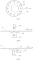
FIGURES 8-10 illustrate some examples of different measurement arrangements. Referring toFIGURE 8 , adeviation sensing unit 810 and asuction unit 910 are provided at opposite sides of the moving cardboard orpaper web 20. The suction unit may be placed under the web and the deviation sensing unit may be placed above the web. This measurement option is simple to implement and the measurement apparatuses require relatively little space under the web. - According to one embodiment a
deviation sensing unit 820 and asuction unit 920 are provided at same side of the movingweb 20, as illustrated inFIGURE 9 . The measurement devices for example, the deviation sensing unit and a suction unit, may be arranged in the connection or in asame measurement unit 30 on the same side of the web. For example, a lens arrangement may be applied to reorientate deviation measurement signal and facilitate sideway positioning of the deviation sensing unit. Thus, the measurement arrangement may require less space. In addition, adjustment of the measurement of the deviation to thehole -
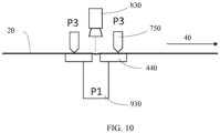
FIGURE 10 shows measurement method with another supporting solution according to one embodiment. A mechanicalweb supporting unit 750 for causing a supporting force P3 to the movingweb 20 against themeasurement plate 440 may be placed above theweb 20. The mechanical supporting force may be provided by mechanical supporting means, such as a clamp or a support rod. - A
suction unit 930 is in this example placed under the web and adeviation sensing unit 830 may be placed above the web. However, it is to be appreciated that various other configurations are feasible, such as placing the suction (and possibly also the deviation sensing) above theweb 20. - The apparatus for elastic modulus on-line measurement of the present invention may be placed before and/or after several different production stages in a cardboard or paper production line. This may provide a possibility to directly optimize cardboard and paper production.
- According to one embodiment the apparatus is or is comprised in a paper or cardboard production machine and adapted for measuring end product of the cardboard or paper web manufacturing process. This enables of measuring the end product directly after manufacturing.
- The present invention provides several advantages. It provides an apparatus by which elastic modulus of the cardboard or paper web can be measured on-line. It provides a possibility to directly optimize properties, for example stiffness, and production costs of the cardboard or paper web, because strength and elastic properties depend heavily on the amount of the raw material, treatments and additives used. The measurement unit is arranged to move in cross direction to the movement of the web, which provides using several measurements points and better measurement accuracy, because composition of the web may vary along the cross direction of the web. The measurement area is possible to define accurately by using the measurement plate with the hole defining the known measurement area. In addition, the measurement method is non-destructive, because the predetermined measurement force is caused by air.
- At least some embodiments are feasible in an on-line measurement of elastic modulus of a moving web.
-
- AI
- artificial intelligence
- CD
- cross direction
- MD
- machine direction
- UI
- user interface
-
- 10
- frame
- 20
- web
- 30
- measurement unit
- 40
- moving direction of web
- 210
- causing predetermined force
- 220
- measuring deviation
- 230
- determining elastic modulus
- 301
- computing unit
- 302
- processor
- 303
- communications unit
- 304
- memory
- 305
- computer program code
- 306
- parameters
- 307
- deviation sensing unit
- 308
- suction unit
- 309
- user interface
- 310
- process automation unit(s)
- 311
- network
- 400
- plane arranged under web
- 410-440
- measurement plate
- 500
- known measurement area
- 510-530
- hole (defining measurement area)
- 600
- used measurement area
- 700-730
- hole (for suction)
- 70
- web support suction unit
- 750
- mechanical web supporting unit
- 810-830
- deviation sensing unit
- 900-930
- suction unit
-
- [1] Timoshenko, S. P., & Woinowsky-Krieger, S. (1959). Theory of Plates and Shells. McGraw-Hill.
- [2] Banichuk, N., Jeronen, J., Neittaanmäki, P., Saksa, T., & Tuovinen, T. (2014). Mechanics of Moving Materials, Volume 207 of Solid Mechanics and Its Applications. Switzerland: Springer.
- [3] Pratt, W. K. (2007). Digital Image Processing: PIKS Scientific Inside (Vol. 4). Hoboken, New Jersey: Wiley-InterScience.
- [4] Knowles, I., & Renka, R. J. (2014). Methods for Numerical Differentiation of Noisy Data. Electronic Journal of Differential Equations, 21(2012), 235-246.
Claims (14)
- An apparatus, comprising:- means (910) for applying suction with a predetermined force in a known measurement area (500) to a moving cardboard or paper web (20) in a manufacturing process,- means (810) for on-line measurement of deviation of the moving cardboard or paper web (20) in the manufacturing process caused by the applied suction in the known measurement area (500), and- means for determining elastic modulus of the moving cardboard or paper web (20), characterized in that the means (810) for on-line measurement of deviation comprise a three-dimensional scanner configured to provide a three-dimensional surface profile of the cardboard or paper web (20) in the measurement area (500) and store a set of coordinate points forming a point cloud, and the elastic modulus is determined on the basis of the three-dimensional surface profile.
- The apparatus of claim 1, wherein at least the means (810) for measuring deviation of the cardboard or paper web (20) is provided in a measurement unit (30) arranged to move in cross direction to the movement (40) of the cardboard or paper web (20).
- The apparatus of claim 1 or 2, wherein the apparatus comprises means (740) for applying suction to the moving cardboard or paper web (20) for causing the moving cardboard or paper web (20) against a surface on at least one side of the known measurement area (500).
- The apparatus of any preceding claim, wherein the apparatus comprises at least one measurement plate (410) to be applied against the moving cardboard or paper web (20) and comprising at least one hole (510, 710) for applying suction to the moving cardboard or paper web (20).
- The apparatus of claim 4, wherein the measurement plate (410) is rotatable in relation to the moving cardboard or paper web (10).
- The apparatus of any preceding claim, wherein the means (910) for applying suction with predetermined force comprises a set of selectable suction levels for applying suction to the moving cardboard or paper web (20).
- The apparatus of any preceding claim, wherein the means for applying suction with predetermined force and the means for on-line measurement of deviation are provided at opposite sides of the moving cardboard or paper web (20).
- The apparatus of any preceding claim, comprising means for determining a value indicative of strain of the moving cardboard or paper web (20) in the direction of movement (40) of the web (20), and
the means for determining elastic modulus is configured to calculate the elastic modulus on the basis of the determined value indicative of the strain. - The apparatus of any preceding claim, wherein the apparatus is or is comprised in a paper or cardboard production machine and adapted for measuring end product properties in the cardboard or paper web (20) manufacturing process.
- The apparatus of claim 1, wherein the apparatus is configured to measure an area (600) extended over the known measurement area (500).
- A method for measurement of elastic modulus of a moving cardboard or paper web (20), comprising:- controlling (210) suction with predetermined force in a known measurement area (500) to a moving cardboard or paper web (20) in a manufacturing process,- detecting (220) on-line measurement information on deviation of the moving cardboard or paper web (20) in the manufacturing process caused by the suction with predetermined force in the known measurement area (500), and- determining (230) elastic modulus of the moving cardboard or paper web (20) in the manufacturing process, characterized in that a three-dimensional surface profile of the cardboard or paper web (20) in the measurement area (500) is provided and a set of coordinate points forming a point cloud is stored, and the elastic modulus is determined on the basis of the three-dimensional surface profile.
- The method of claim 11, wherein suction is applied to the moving cardboard or paper web (20) for causing the moving cardboard or paper web (20) against a surface on at least one side of the known measurement area.
- The method of claim 11, wherein an area (600) extended over the known measurement area (500) is measured.
- A computer program, comprising computer program code configured for, when executed in a processor (302) of a computing device (301) for an elastic modulus measurement system as defined in claim 1, causing the computing device to perform the method of claim 11.
Applications Claiming Priority (2)
| Application Number | Priority Date | Filing Date | Title |
|---|---|---|---|
| FI20185410A FI20185410A1 (en) | 2018-05-03 | 2018-05-03 | Measurement of elastic modulus of moving web |
| PCT/FI2019/050327 WO2019211515A2 (en) | 2018-05-03 | 2019-04-24 | Measurement of elastic modulus of moving web |
Publications (3)
| Publication Number | Publication Date |
|---|---|
| EP3788338A2 EP3788338A2 (en) | 2021-03-10 |
| EP3788338A4 EP3788338A4 (en) | 2021-05-19 |
| EP3788338B1 true EP3788338B1 (en) | 2023-09-06 |
Family
ID=68387090
Family Applications (1)
| Application Number | Title | Priority Date | Filing Date |
|---|---|---|---|
| EP19796814.2A Active EP3788338B1 (en) | 2018-05-03 | 2019-04-24 | Measurement of elastic modulus of moving web |
Country Status (6)
| Country | Link |
|---|---|
| US (1) | US11828736B2 (en) |
| EP (1) | EP3788338B1 (en) |
| CN (1) | CN112074717B (en) |
| CA (1) | CA3098269A1 (en) |
| FI (1) | FI20185410A1 (en) |
| WO (1) | WO2019211515A2 (en) |
Families Citing this family (2)
| Publication number | Priority date | Publication date | Assignee | Title |
|---|---|---|---|---|
| KR102825695B1 (en) * | 2020-06-23 | 2025-06-27 | 주식회사 엘지에너지솔루션 | System and method for testing fatigue of metal foil |
| JP2024110706A (en) * | 2023-02-03 | 2024-08-16 | 株式会社日立製作所 | Reuse system and method |
Family Cites Families (21)
| Publication number | Priority date | Publication date | Assignee | Title |
|---|---|---|---|---|
| BE758342A (en) * | 1969-11-15 | 1971-05-03 | Gevaert Agfa Agfa N V | METHOD OF MEASURING THE TENSION IN MATERIAL JOBS |
| CA919937A (en) * | 1969-11-24 | 1973-01-30 | Consolidated-Bathurst Limited | Paper machine tension tester |
| US4866984A (en) * | 1985-10-04 | 1989-09-19 | Measurex Corporation | Sensor and system for continuous determination of paper strength |
| DE3787227T2 (en) * | 1986-07-18 | 1994-04-07 | Measurex Corp | Sensor for determining the thickness of band-shaped materials. |
| US5029469A (en) * | 1988-06-17 | 1991-07-09 | Measurex Corporation | Sheet tension sensor |
| FI114337B (en) * | 2001-07-03 | 2004-09-30 | Metso Automation Oy | Method and gauge for measuring at least one property of a moving web |
| US6588118B2 (en) * | 2001-10-10 | 2003-07-08 | Abb Inc. | Non-contact sheet sensing system and related method |
| US6936137B2 (en) * | 2001-10-24 | 2005-08-30 | Honeywell International Inc. | Air clamp stabilizer for continuous web materials |
| US6993964B2 (en) * | 2004-02-04 | 2006-02-07 | The Procter & Gamble Company | Method of determining a modulus of elasticity of a moving web material |
| DE102007033394A1 (en) | 2007-07-18 | 2009-01-22 | Voith Patent Gmbh | Method and system for online determination of at least one elongation property of a running paper or board web |
| WO2009032094A1 (en) | 2007-08-31 | 2009-03-12 | Abb Ltd. | Web thickness measurement device |
| US9045306B2 (en) | 2007-11-27 | 2015-06-02 | Abb Ltd. | Sheet stabilizer with suction nozzle having center protrusion |
| US8083895B2 (en) | 2008-04-18 | 2011-12-27 | Honeywell Asca Inc. | Sheet stabilization with dual opposing cross direction air clamps |
| US8083896B2 (en) * | 2008-09-26 | 2011-12-27 | Honeywell Asca Inc. | Pressure equalizing baffle and coanda air clamp |
| US9044175B2 (en) * | 2009-11-18 | 2015-06-02 | Hitachi Medical Corporation | Ultrasonic diagnostic apparatus and three-dimensional elastic ratio calculating method |
| WO2013007864A1 (en) | 2011-07-08 | 2013-01-17 | Metso Automation Oy | Method and measuring device for measuring caliper of moving fibre web |
| US8958898B2 (en) * | 2011-11-07 | 2015-02-17 | Nalco Company | Method and apparatus to monitor and control sheet characteristics on a creping process |
| WO2013116299A1 (en) | 2012-01-31 | 2013-08-08 | 3M Innovative Properties Company | Method and apparatus for measuring the three dimensional structure of a surface |
| FI125811B (en) | 2013-05-29 | 2016-02-29 | Valmet Automation Oy | Track measurement |
| JP6419101B2 (en) | 2016-03-23 | 2018-11-07 | 株式会社ホニック | Corrugated molding inspection method |
| FI130248B (en) * | 2019-09-23 | 2023-05-08 | Valmet Automation Oy | Measurement apparatus and method of paper web |
-
2018
- 2018-05-03 FI FI20185410A patent/FI20185410A1/en not_active Application Discontinuation
-
2019
- 2019-04-24 EP EP19796814.2A patent/EP3788338B1/en active Active
- 2019-04-24 US US17/052,537 patent/US11828736B2/en active Active
- 2019-04-24 CN CN201980029952.7A patent/CN112074717B/en active Active
- 2019-04-24 CA CA3098269A patent/CA3098269A1/en active Pending
- 2019-04-24 WO PCT/FI2019/050327 patent/WO2019211515A2/en not_active Ceased
Also Published As
| Publication number | Publication date |
|---|---|
| US11828736B2 (en) | 2023-11-28 |
| WO2019211515A2 (en) | 2019-11-07 |
| EP3788338A4 (en) | 2021-05-19 |
| WO2019211515A3 (en) | 2020-01-16 |
| EP3788338A2 (en) | 2021-03-10 |
| CN112074717B (en) | 2024-01-19 |
| CN112074717A (en) | 2020-12-11 |
| CA3098269A1 (en) | 2019-11-07 |
| FI20185410A1 (en) | 2019-11-04 |
| US20210239583A1 (en) | 2021-08-05 |
Similar Documents
| Publication | Publication Date | Title |
|---|---|---|
| US20070229846A1 (en) | Thickness measurement of moving webs and seal integrity system using dual interferometer | |
| US11828736B2 (en) | Measurement of elastic modulus of moving web | |
| US12174231B2 (en) | Measurement device and measurement method | |
| CN113804696B (en) | Method for determining size and area of defect on surface of bar | |
| Fadiji et al. | Evaluating the displacement field of paperboard packages subjected to compression loading using digital image correlation (DIC) | |
| US20170205224A1 (en) | Method for manufacturing component and manufacturing apparatus using such method, and volume measuring method | |
| KR102930116B1 (en) | System and method for measuring tension distribution in a web in a roll-to-roll process | |
| Pai et al. | Locating structural damage by detecting boundary effects | |
| JP6329562B2 (en) | Surface deformation measuring device | |
| JPH10286627A (en) | Work inclination angle measuring method, work bend angle measuring method, work inclination quantity measuring instrument and work bend angle measuring instrument | |
| Djuzhev et al. | Non-destructive method of surface mapping to improve accuracy of mechanical stresses measurements | |
| Müller et al. | Method for Fast Quality Evaluation of Deep‐drawn Paperboard Packaging Components | |
| Hemming et al. | Interferometric step gauge for CMM verification | |
| US20190316999A1 (en) | Wound roll quality instrument and method | |
| KR102442240B1 (en) | Distance sensors, placement systems and methods | |
| Salo et al. | Paper bending stiffness and web tension measurement from a running web using a vacuum and computer imaging | |
| Ojer et al. | Automatic inspection of paperboard creases to improve the quality of the packaging process | |
| KR101033031B1 (en) | Strain measuring device | |
| JP5234941B2 (en) | Alignment device | |
| Díaz et al. | Identification of crack tip location using edge detection algorithms and artificially generated displacement fields | |
| JP2015175628A (en) | Stress distribution measurement instrument, strain distribution measurement instrument, and stress distribution measurement program | |
| Shi et al. | Online optical inspection of air permeability of packaging materials during laser perforation | |
| Salo et al. | Plate Bending Models for Paper Manufacturing Processes and Comparisons to Simulations with Finite Element Methods | |
| Chen et al. | Out-of-Plane Vibration Frequency Estimation for Flexible Substrate in Roll-to-Roll Processing | |
| WO2016152816A1 (en) | Film flatness inspection device and film flatness inspection method |
Legal Events
| Date | Code | Title | Description |
|---|---|---|---|
| STAA | Information on the status of an ep patent application or granted ep patent |
Free format text: STATUS: THE INTERNATIONAL PUBLICATION HAS BEEN MADE |
|
| PUAI | Public reference made under article 153(3) epc to a published international application that has entered the european phase |
Free format text: ORIGINAL CODE: 0009012 |
|
| STAA | Information on the status of an ep patent application or granted ep patent |
Free format text: STATUS: REQUEST FOR EXAMINATION WAS MADE |
|
| 17P | Request for examination filed |
Effective date: 20201027 |
|
| AK | Designated contracting states |
Kind code of ref document: A2 Designated state(s): AL AT BE BG CH CY CZ DE DK EE ES FI FR GB GR HR HU IE IS IT LI LT LU LV MC MK MT NL NO PL PT RO RS SE SI SK SM TR |
|
| AX | Request for extension of the european patent |
Extension state: BA ME |
|
| A4 | Supplementary search report drawn up and despatched |
Effective date: 20210416 |
|
| RIC1 | Information provided on ipc code assigned before grant |
Ipc: G01L 5/08 20060101AFI20210413BHEP Ipc: G01B 11/16 20060101ALI20210413BHEP Ipc: G01B 11/24 20060101ALI20210413BHEP Ipc: G01N 3/10 20060101ALI20210413BHEP Ipc: G01N 33/34 20060101ALI20210413BHEP Ipc: D21F 7/06 20060101ALI20210413BHEP Ipc: D21G 9/00 20060101ALI20210413BHEP Ipc: G01N 33/36 20060101ALI20210413BHEP Ipc: B65H 20/14 20060101ALI20210413BHEP Ipc: G01N 3/00 20060101ALI20210413BHEP Ipc: G01L 5/04 20060101ALI20210413BHEP |
|
| DAV | Request for validation of the european patent (deleted) | ||
| DAX | Request for extension of the european patent (deleted) | ||
| STAA | Information on the status of an ep patent application or granted ep patent |
Free format text: STATUS: EXAMINATION IS IN PROGRESS |
|
| 17Q | First examination report despatched |
Effective date: 20211104 |
|
| GRAP | Despatch of communication of intention to grant a patent |
Free format text: ORIGINAL CODE: EPIDOSNIGR1 |
|
| STAA | Information on the status of an ep patent application or granted ep patent |
Free format text: STATUS: GRANT OF PATENT IS INTENDED |
|
| INTG | Intention to grant announced |
Effective date: 20230406 |
|
| GRAS | Grant fee paid |
Free format text: ORIGINAL CODE: EPIDOSNIGR3 |
|
| GRAA | (expected) grant |
Free format text: ORIGINAL CODE: 0009210 |
|
| STAA | Information on the status of an ep patent application or granted ep patent |
Free format text: STATUS: THE PATENT HAS BEEN GRANTED |
|
| AK | Designated contracting states |
Kind code of ref document: B1 Designated state(s): AL AT BE BG CH CY CZ DE DK EE ES FI FR GB GR HR HU IE IS IT LI LT LU LV MC MK MT NL NO PL PT RO RS SE SI SK SM TR |
|
| REG | Reference to a national code |
Ref country code: GB Ref legal event code: FG4D |
|
| REG | Reference to a national code |
Ref country code: CH Ref legal event code: EP |
|
| REG | Reference to a national code |
Ref country code: IE Ref legal event code: FG4D |
|
| REG | Reference to a national code |
Ref country code: DE Ref legal event code: R096 Ref document number: 602019036940 Country of ref document: DE |
|
| REG | Reference to a national code |
Ref country code: LT Ref legal event code: MG9D |
|
| REG | Reference to a national code |
Ref country code: NL Ref legal event code: MP Effective date: 20230906 |
|
| PG25 | Lapsed in a contracting state [announced via postgrant information from national office to epo] |
Ref country code: GR Free format text: LAPSE BECAUSE OF FAILURE TO SUBMIT A TRANSLATION OF THE DESCRIPTION OR TO PAY THE FEE WITHIN THE PRESCRIBED TIME-LIMIT Effective date: 20231207 |
|
| PG25 | Lapsed in a contracting state [announced via postgrant information from national office to epo] |
Ref country code: SE Free format text: LAPSE BECAUSE OF FAILURE TO SUBMIT A TRANSLATION OF THE DESCRIPTION OR TO PAY THE FEE WITHIN THE PRESCRIBED TIME-LIMIT Effective date: 20230906 Ref country code: RS Free format text: LAPSE BECAUSE OF FAILURE TO SUBMIT A TRANSLATION OF THE DESCRIPTION OR TO PAY THE FEE WITHIN THE PRESCRIBED TIME-LIMIT Effective date: 20230906 Ref country code: NO Free format text: LAPSE BECAUSE OF FAILURE TO SUBMIT A TRANSLATION OF THE DESCRIPTION OR TO PAY THE FEE WITHIN THE PRESCRIBED TIME-LIMIT Effective date: 20231206 Ref country code: LV Free format text: LAPSE BECAUSE OF FAILURE TO SUBMIT A TRANSLATION OF THE DESCRIPTION OR TO PAY THE FEE WITHIN THE PRESCRIBED TIME-LIMIT Effective date: 20230906 Ref country code: LT Free format text: LAPSE BECAUSE OF FAILURE TO SUBMIT A TRANSLATION OF THE DESCRIPTION OR TO PAY THE FEE WITHIN THE PRESCRIBED TIME-LIMIT Effective date: 20230906 Ref country code: HR Free format text: LAPSE BECAUSE OF FAILURE TO SUBMIT A TRANSLATION OF THE DESCRIPTION OR TO PAY THE FEE WITHIN THE PRESCRIBED TIME-LIMIT Effective date: 20230906 Ref country code: GR Free format text: LAPSE BECAUSE OF FAILURE TO SUBMIT A TRANSLATION OF THE DESCRIPTION OR TO PAY THE FEE WITHIN THE PRESCRIBED TIME-LIMIT Effective date: 20231207 Ref country code: FI Free format text: LAPSE BECAUSE OF FAILURE TO SUBMIT A TRANSLATION OF THE DESCRIPTION OR TO PAY THE FEE WITHIN THE PRESCRIBED TIME-LIMIT Effective date: 20230906 |
|
| REG | Reference to a national code |
Ref country code: AT Ref legal event code: MK05 Ref document number: 1609124 Country of ref document: AT Kind code of ref document: T Effective date: 20230906 |
|
| PG25 | Lapsed in a contracting state [announced via postgrant information from national office to epo] |
Ref country code: NL Free format text: LAPSE BECAUSE OF FAILURE TO SUBMIT A TRANSLATION OF THE DESCRIPTION OR TO PAY THE FEE WITHIN THE PRESCRIBED TIME-LIMIT Effective date: 20230906 |
|
| PG25 | Lapsed in a contracting state [announced via postgrant information from national office to epo] |
Ref country code: IS Free format text: LAPSE BECAUSE OF FAILURE TO SUBMIT A TRANSLATION OF THE DESCRIPTION OR TO PAY THE FEE WITHIN THE PRESCRIBED TIME-LIMIT Effective date: 20240106 |
|
| PG25 | Lapsed in a contracting state [announced via postgrant information from national office to epo] |
Ref country code: AT Free format text: LAPSE BECAUSE OF FAILURE TO SUBMIT A TRANSLATION OF THE DESCRIPTION OR TO PAY THE FEE WITHIN THE PRESCRIBED TIME-LIMIT Effective date: 20230906 |
|
| PG25 | Lapsed in a contracting state [announced via postgrant information from national office to epo] |
Ref country code: ES Free format text: LAPSE BECAUSE OF FAILURE TO SUBMIT A TRANSLATION OF THE DESCRIPTION OR TO PAY THE FEE WITHIN THE PRESCRIBED TIME-LIMIT Effective date: 20230906 |
|
| PG25 | Lapsed in a contracting state [announced via postgrant information from national office to epo] |
Ref country code: SM Free format text: LAPSE BECAUSE OF FAILURE TO SUBMIT A TRANSLATION OF THE DESCRIPTION OR TO PAY THE FEE WITHIN THE PRESCRIBED TIME-LIMIT Effective date: 20230906 Ref country code: RO Free format text: LAPSE BECAUSE OF FAILURE TO SUBMIT A TRANSLATION OF THE DESCRIPTION OR TO PAY THE FEE WITHIN THE PRESCRIBED TIME-LIMIT Effective date: 20230906 Ref country code: IS Free format text: LAPSE BECAUSE OF FAILURE TO SUBMIT A TRANSLATION OF THE DESCRIPTION OR TO PAY THE FEE WITHIN THE PRESCRIBED TIME-LIMIT Effective date: 20240106 Ref country code: ES Free format text: LAPSE BECAUSE OF FAILURE TO SUBMIT A TRANSLATION OF THE DESCRIPTION OR TO PAY THE FEE WITHIN THE PRESCRIBED TIME-LIMIT Effective date: 20230906 Ref country code: EE Free format text: LAPSE BECAUSE OF FAILURE TO SUBMIT A TRANSLATION OF THE DESCRIPTION OR TO PAY THE FEE WITHIN THE PRESCRIBED TIME-LIMIT Effective date: 20230906 Ref country code: CZ Free format text: LAPSE BECAUSE OF FAILURE TO SUBMIT A TRANSLATION OF THE DESCRIPTION OR TO PAY THE FEE WITHIN THE PRESCRIBED TIME-LIMIT Effective date: 20230906 Ref country code: AT Free format text: LAPSE BECAUSE OF FAILURE TO SUBMIT A TRANSLATION OF THE DESCRIPTION OR TO PAY THE FEE WITHIN THE PRESCRIBED TIME-LIMIT Effective date: 20230906 Ref country code: SK Free format text: LAPSE BECAUSE OF FAILURE TO SUBMIT A TRANSLATION OF THE DESCRIPTION OR TO PAY THE FEE WITHIN THE PRESCRIBED TIME-LIMIT Effective date: 20230906 Ref country code: PT Free format text: LAPSE BECAUSE OF FAILURE TO SUBMIT A TRANSLATION OF THE DESCRIPTION OR TO PAY THE FEE WITHIN THE PRESCRIBED TIME-LIMIT Effective date: 20240108 |
|
| PG25 | Lapsed in a contracting state [announced via postgrant information from national office to epo] |
Ref country code: PL Free format text: LAPSE BECAUSE OF FAILURE TO SUBMIT A TRANSLATION OF THE DESCRIPTION OR TO PAY THE FEE WITHIN THE PRESCRIBED TIME-LIMIT Effective date: 20230906 Ref country code: IT Free format text: LAPSE BECAUSE OF FAILURE TO SUBMIT A TRANSLATION OF THE DESCRIPTION OR TO PAY THE FEE WITHIN THE PRESCRIBED TIME-LIMIT Effective date: 20230906 |
|
| REG | Reference to a national code |
Ref country code: DE Ref legal event code: R097 Ref document number: 602019036940 Country of ref document: DE |
|
| PG25 | Lapsed in a contracting state [announced via postgrant information from national office to epo] |
Ref country code: DK Free format text: LAPSE BECAUSE OF FAILURE TO SUBMIT A TRANSLATION OF THE DESCRIPTION OR TO PAY THE FEE WITHIN THE PRESCRIBED TIME-LIMIT Effective date: 20230906 |
|
| PLBE | No opposition filed within time limit |
Free format text: ORIGINAL CODE: 0009261 |
|
| STAA | Information on the status of an ep patent application or granted ep patent |
Free format text: STATUS: NO OPPOSITION FILED WITHIN TIME LIMIT |
|
| PG25 | Lapsed in a contracting state [announced via postgrant information from national office to epo] |
Ref country code: DK Free format text: LAPSE BECAUSE OF FAILURE TO SUBMIT A TRANSLATION OF THE DESCRIPTION OR TO PAY THE FEE WITHIN THE PRESCRIBED TIME-LIMIT Effective date: 20230906 Ref country code: SI Free format text: LAPSE BECAUSE OF FAILURE TO SUBMIT A TRANSLATION OF THE DESCRIPTION OR TO PAY THE FEE WITHIN THE PRESCRIBED TIME-LIMIT Effective date: 20230906 |
|
| 26N | No opposition filed |
Effective date: 20240607 |
|
| PG25 | Lapsed in a contracting state [announced via postgrant information from national office to epo] |
Ref country code: BG Free format text: LAPSE BECAUSE OF FAILURE TO SUBMIT A TRANSLATION OF THE DESCRIPTION OR TO PAY THE FEE WITHIN THE PRESCRIBED TIME-LIMIT Effective date: 20230906 |
|
| PG25 | Lapsed in a contracting state [announced via postgrant information from national office to epo] |
Ref country code: MC Free format text: LAPSE BECAUSE OF FAILURE TO SUBMIT A TRANSLATION OF THE DESCRIPTION OR TO PAY THE FEE WITHIN THE PRESCRIBED TIME-LIMIT Effective date: 20230906 |
|
| PG25 | Lapsed in a contracting state [announced via postgrant information from national office to epo] |
Ref country code: MC Free format text: LAPSE BECAUSE OF FAILURE TO SUBMIT A TRANSLATION OF THE DESCRIPTION OR TO PAY THE FEE WITHIN THE PRESCRIBED TIME-LIMIT Effective date: 20230906 Ref country code: BG Free format text: LAPSE BECAUSE OF FAILURE TO SUBMIT A TRANSLATION OF THE DESCRIPTION OR TO PAY THE FEE WITHIN THE PRESCRIBED TIME-LIMIT Effective date: 20230906 |
|
| REG | Reference to a national code |
Ref country code: CH Ref legal event code: PL |
|
| PG25 | Lapsed in a contracting state [announced via postgrant information from national office to epo] |
Ref country code: LU Free format text: LAPSE BECAUSE OF NON-PAYMENT OF DUE FEES Effective date: 20240424 |
|
| GBPC | Gb: european patent ceased through non-payment of renewal fee |
Effective date: 20240424 |
|
| REG | Reference to a national code |
Ref country code: BE Ref legal event code: MM Effective date: 20240430 |
|
| PG25 | Lapsed in a contracting state [announced via postgrant information from national office to epo] |
Ref country code: LU Free format text: LAPSE BECAUSE OF NON-PAYMENT OF DUE FEES Effective date: 20240424 |
|
| PG25 | Lapsed in a contracting state [announced via postgrant information from national office to epo] |
Ref country code: BE Free format text: LAPSE BECAUSE OF NON-PAYMENT OF DUE FEES Effective date: 20240430 |
|
| PG25 | Lapsed in a contracting state [announced via postgrant information from national office to epo] |
Ref country code: GB Free format text: LAPSE BECAUSE OF NON-PAYMENT OF DUE FEES Effective date: 20240424 |
|
| PG25 | Lapsed in a contracting state [announced via postgrant information from national office to epo] |
Ref country code: GB Free format text: LAPSE BECAUSE OF NON-PAYMENT OF DUE FEES Effective date: 20240424 Ref country code: BE Free format text: LAPSE BECAUSE OF NON-PAYMENT OF DUE FEES Effective date: 20240430 Ref country code: CH Free format text: LAPSE BECAUSE OF NON-PAYMENT OF DUE FEES Effective date: 20240430 |
|
| PG25 | Lapsed in a contracting state [announced via postgrant information from national office to epo] |
Ref country code: IE Free format text: LAPSE BECAUSE OF NON-PAYMENT OF DUE FEES Effective date: 20240424 |
|
| PGFP | Annual fee paid to national office [announced via postgrant information from national office to epo] |
Ref country code: DE Payment date: 20250422 Year of fee payment: 7 |
|
| PGFP | Annual fee paid to national office [announced via postgrant information from national office to epo] |
Ref country code: FR Payment date: 20250425 Year of fee payment: 7 |
|
| PG25 | Lapsed in a contracting state [announced via postgrant information from national office to epo] |
Ref country code: CY Free format text: LAPSE BECAUSE OF FAILURE TO SUBMIT A TRANSLATION OF THE DESCRIPTION OR TO PAY THE FEE WITHIN THE PRESCRIBED TIME-LIMIT; INVALID AB INITIO Effective date: 20190424 |
|
| PG25 | Lapsed in a contracting state [announced via postgrant information from national office to epo] |
Ref country code: HU Free format text: LAPSE BECAUSE OF FAILURE TO SUBMIT A TRANSLATION OF THE DESCRIPTION OR TO PAY THE FEE WITHIN THE PRESCRIBED TIME-LIMIT; INVALID AB INITIO Effective date: 20190424 |