EP3788280B1 - A valve sealing arrangement and a valve seat - Google Patents
A valve sealing arrangement and a valve seat Download PDFInfo
- Publication number
- EP3788280B1 EP3788280B1 EP18917047.5A EP18917047A EP3788280B1 EP 3788280 B1 EP3788280 B1 EP 3788280B1 EP 18917047 A EP18917047 A EP 18917047A EP 3788280 B1 EP3788280 B1 EP 3788280B1
- Authority
- EP
- European Patent Office
- Prior art keywords
- bellow
- seat
- valve
- sealing
- closing member
- Prior art date
- Legal status (The legal status is an assumption and is not a legal conclusion. Google has not performed a legal analysis and makes no representation as to the accuracy of the status listed.)
- Active
Links
Images


Classifications
-
- F—MECHANICAL ENGINEERING; LIGHTING; HEATING; WEAPONS; BLASTING
- F16—ENGINEERING ELEMENTS AND UNITS; GENERAL MEASURES FOR PRODUCING AND MAINTAINING EFFECTIVE FUNCTIONING OF MACHINES OR INSTALLATIONS; THERMAL INSULATION IN GENERAL
- F16J—PISTONS; CYLINDERS; SEALINGS
- F16J15/00—Sealings
- F16J15/16—Sealings between relatively-moving surfaces
- F16J15/34—Sealings between relatively-moving surfaces with slip-ring pressed against a more or less radial face on one member
- F16J15/3464—Mounting of the seal
- F16J15/3472—Means for centering or aligning the contacting faces
-
- F—MECHANICAL ENGINEERING; LIGHTING; HEATING; WEAPONS; BLASTING
- F16—ENGINEERING ELEMENTS AND UNITS; GENERAL MEASURES FOR PRODUCING AND MAINTAINING EFFECTIVE FUNCTIONING OF MACHINES OR INSTALLATIONS; THERMAL INSULATION IN GENERAL
- F16K—VALVES; TAPS; COCKS; ACTUATING-FLOATS; DEVICES FOR VENTING OR AERATING
- F16K5/00—Plug valves; Taps or cocks comprising only cut-off apparatus having at least one of the sealing faces shaped as a more or less complete surface of a solid of revolution, the opening and closing movement being predominantly rotary
- F16K5/08—Details
- F16K5/14—Special arrangements for separating the sealing faces or for pressing them together
- F16K5/20—Special arrangements for separating the sealing faces or for pressing them together for plugs with spherical surfaces
- F16K5/205—Sealing effected by the flowing medium
- F16K5/207—Sealing effected by the flowing medium using bellows
-
- F—MECHANICAL ENGINEERING; LIGHTING; HEATING; WEAPONS; BLASTING
- F16—ENGINEERING ELEMENTS AND UNITS; GENERAL MEASURES FOR PRODUCING AND MAINTAINING EFFECTIVE FUNCTIONING OF MACHINES OR INSTALLATIONS; THERMAL INSULATION IN GENERAL
- F16J—PISTONS; CYLINDERS; SEALINGS
- F16J15/00—Sealings
- F16J15/16—Sealings between relatively-moving surfaces
- F16J15/34—Sealings between relatively-moving surfaces with slip-ring pressed against a more or less radial face on one member
- F16J15/36—Sealings between relatively-moving surfaces with slip-ring pressed against a more or less radial face on one member connected by a diaphragm or bellow to the other member
-
- F—MECHANICAL ENGINEERING; LIGHTING; HEATING; WEAPONS; BLASTING
- F16—ENGINEERING ELEMENTS AND UNITS; GENERAL MEASURES FOR PRODUCING AND MAINTAINING EFFECTIVE FUNCTIONING OF MACHINES OR INSTALLATIONS; THERMAL INSULATION IN GENERAL
- F16K—VALVES; TAPS; COCKS; ACTUATING-FLOATS; DEVICES FOR VENTING OR AERATING
- F16K5/00—Plug valves; Taps or cocks comprising only cut-off apparatus having at least one of the sealing faces shaped as a more or less complete surface of a solid of revolution, the opening and closing movement being predominantly rotary
- F16K5/06—Plug valves; Taps or cocks comprising only cut-off apparatus having at least one of the sealing faces shaped as a more or less complete surface of a solid of revolution, the opening and closing movement being predominantly rotary with plugs having spherical surfaces; Packings therefor
- F16K5/0663—Packings
-
- F—MECHANICAL ENGINEERING; LIGHTING; HEATING; WEAPONS; BLASTING
- F16—ENGINEERING ELEMENTS AND UNITS; GENERAL MEASURES FOR PRODUCING AND MAINTAINING EFFECTIVE FUNCTIONING OF MACHINES OR INSTALLATIONS; THERMAL INSULATION IN GENERAL
- F16K—VALVES; TAPS; COCKS; ACTUATING-FLOATS; DEVICES FOR VENTING OR AERATING
- F16K5/00—Plug valves; Taps or cocks comprising only cut-off apparatus having at least one of the sealing faces shaped as a more or less complete surface of a solid of revolution, the opening and closing movement being predominantly rotary
- F16K5/06—Plug valves; Taps or cocks comprising only cut-off apparatus having at least one of the sealing faces shaped as a more or less complete surface of a solid of revolution, the opening and closing movement being predominantly rotary with plugs having spherical surfaces; Packings therefor
- F16K5/0663—Packings
- F16K5/0668—Single packings
-
- F—MECHANICAL ENGINEERING; LIGHTING; HEATING; WEAPONS; BLASTING
- F16—ENGINEERING ELEMENTS AND UNITS; GENERAL MEASURES FOR PRODUCING AND MAINTAINING EFFECTIVE FUNCTIONING OF MACHINES OR INSTALLATIONS; THERMAL INSULATION IN GENERAL
- F16K—VALVES; TAPS; COCKS; ACTUATING-FLOATS; DEVICES FOR VENTING OR AERATING
- F16K5/00—Plug valves; Taps or cocks comprising only cut-off apparatus having at least one of the sealing faces shaped as a more or less complete surface of a solid of revolution, the opening and closing movement being predominantly rotary
- F16K5/06—Plug valves; Taps or cocks comprising only cut-off apparatus having at least one of the sealing faces shaped as a more or less complete surface of a solid of revolution, the opening and closing movement being predominantly rotary with plugs having spherical surfaces; Packings therefor
- F16K5/0663—Packings
- F16K5/0689—Packings between housing and plug
-
- F—MECHANICAL ENGINEERING; LIGHTING; HEATING; WEAPONS; BLASTING
- F16—ENGINEERING ELEMENTS AND UNITS; GENERAL MEASURES FOR PRODUCING AND MAINTAINING EFFECTIVE FUNCTIONING OF MACHINES OR INSTALLATIONS; THERMAL INSULATION IN GENERAL
- F16K—VALVES; TAPS; COCKS; ACTUATING-FLOATS; DEVICES FOR VENTING OR AERATING
- F16K5/00—Plug valves; Taps or cocks comprising only cut-off apparatus having at least one of the sealing faces shaped as a more or less complete surface of a solid of revolution, the opening and closing movement being predominantly rotary
- F16K5/08—Details
- F16K5/14—Special arrangements for separating the sealing faces or for pressing them together
- F16K5/20—Special arrangements for separating the sealing faces or for pressing them together for plugs with spherical surfaces
Definitions
- This invention relates to a valve sealing arrangement.
- valve arrangement in which a valve body is provided with a flow channel, a closing member and a seat.
- the seat is arranged inside the valve body and against the closing member in order to provide a close-fitting connection.
- a typical seat type is a bellows seat. Solutions involving such bellows are disclosed in US 2018/0038491A1 and JP 2006 017237A , for instance.
- Figure 1 illustrates a cross-sectional, general view of a valve arrangement.
- the valve in Figure 1 is, by way of example, a ball valve.
- Figure 1 shows a valve body 1, a closing member 2 and a seat 3.
- the seat 3 is made of metal.
- the seat 3 is positioned such that it makes contact with both the valve body 1 and the closing member 2 in order to prevent leakage around the seat.
- the seat is positioned only on one side of the closing member.
- the valve arrangement may comprise seats on both sides of the closing member.
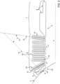
- Figure 2 shows a cross-sectional view of the valve sealing arrangement with the seat 3 and a section of the closing member 2.
- the seat 3 comprises a center axis 4, a sealing portion 5 with a first sealing surface 8 for making contact with the closing member 2, and a back-sealing portion 7 with a second sealing surface 9 for making contact with the inner surface of the valve body 1.
- a separate back seal e.g. an O-ring or a graphite sealing (not shown in the Figures) may be used to provide a fluid-tight sealing between the seat and the valve body.
- the contact area between the sealing portion 5 and the closing member 2 is later in this text referred to as a closing member contact surface 18.
- Said closing member contact surface 18 may be, for instance, spherical.
- the seat 3 is further provided with a bellows 6 between the first sealing surface 8 and the second sealing surface 9.
- the bellows 6 comprises bellow members 10 wherein adjacent bellow walls form either an inwardly open fold 32 or an outwardly open fold 33 and a series of such folds form the bellows 6.
- an inwardly open fold refers to a fold which is open towards the center axis 4
- an outwardly open fold refers to a fold that is open away from the center axis 4.
- the center axis 4 is preferably a straight line, i.e. axes of revolution of said bellow members are coaxial.
- the bellow members are illustrated as being of same shape, but the individual bellow members could also be of different shape or size.
- one or more of the bellow members 10 located closest to the first sealing surface 8 extend in a direction where the center axis 11 of said bellow member 10 forms a substantially perpendicular first angle 12 with a surface normal 13 of the closing member contact surface 18. Furthermore, a bellow member 15 located further away from the first sealing surface 18 extends in a direction which forms a second angle 14 with said surface normal 13 of the closing member contact surface 18 which second angle 14 is smaller than the first angle 12. In addition, one or more of the bellow members located furthest away from the first sealing surface 8 may extend in a direction, which is substantially parallel to the surface normal 13 of the closing member contact surface 18.
- the surface normal 13 discussed here refers to a surface normal projecting from the middle of the closing member contact surface 18.
- the seat 3 comprises several bellow members wherein one or more of said bellow members comprises two straight sections, which are substantially parallel.
- one or more of the bellow members 10 extends in a direction that is oblique to the center axis 4 of said seat.
- a seat comprising bellow members extending only in a direction that is perpendicular to the central axis of the seat, i.e. in a radial direction, is unnecessarily rigid in the radial direction.
- Such a seat is unable to adjust to the possible displacement or deformation of the closing member in the radial direction due to a pressure load in the valve. Moreover, this may result in a non-uniform contact pressure distribution on the closing member contact surface and leaking of the valve.
- a seat comprising one or more bellow members extending in a direction that is oblique to the center axis of said seat, is much more flexible in the radial direction and such a structure is better able to adjust to the displacement and deformation of the closing member. Therefore, such a structure is advantageous as it is able to direct the spring force of the bellows such that a more uniform contact pressure distribution is formed on the closing member contact surface.
- Figure 3 illustrates a second arrangement, where, by way of example, the angle between the surface normal 13 of the closing member contact surface 18 and the center axes of said bellow members gradually decreases when moving away from the first sealing surface 8 towards the second sealing surface 9. Moreover, said angles decrease in such a way, that the center axes near the first sealing surface 8 form nearly perpendicular angles with said surface normal 13, and the center axes near the second sealing surface 9 may be even substantially parallel with said surface normal 13.
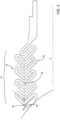
- Figure 4 illustrates an embodiment of the invention wherein at least one of the bellow members is a bent bellow member.
- the bellows comprises of several bent bellow members 19 arranged in an arrow-like formation to form a tree-like bellows structure 21.
- a bellow member comprises two folds, or fold sections, which extend in different directions, said directions being substantially perpendicular to each other.
- the arrow-like, bent bellow members are pointing towards the closing member contact surface 18.
- the arrow-like, bent bellow members may be arranged to point in the opposite direction, for instance.
- a tree-like bellows structure 21 is advantageous, as more material for the spring can be packed in a smaller volume.
- the bellow members closest to the first sealing surface and the bellow member closest to the second sealing surface extend in directions which are oblique the center axis of the seat.
- the tip points 22 of the arrow-like, bent bellow members 19 are located on a same, horizontal line 23 and the lengths of said folds are approximately equal.
- the tip points 22 may be located such that they do not share a common line and lengths of the folds may vary as well.
- a bellow member may comprise more than two folds.
- the seat of Figures 1-4 may be manufactured e.g. by means of additive manufacturing.
- additive manufacturing is beneficial, as the bellows dimensions, such as the wall thickness, may be freely varied and the bellows may be arranged in essentially any position with regard to the surface normal 13 of the first sealing surface 8, thus enabling the production of a more compact seat with an improved pressure distribution control on the sealing surfaces and enhanced durability due to more even stress distribution on the contact surfaces with the closing member and with the valve body.
- Additive manufacturing may be carried out by using a material containing nickel, such as a nickel superalloy and furthermore an Inconel TM alloy, furthermore an Inconel TM 625 or 718 alloy, where Inconel TM is a trademark of Huntington Alloys Corporation.
- a stainless steel alloy such as an AISI 316, or a titanium alloy.
- the bellow members closest to the first sealing surface and the bellow member closest to the second sealing surface extend in directions which are oblique the center axis of the seat.
- all bellow members extend in directions, which are oblique to the center axis of the seat.
- the bellows comprises bellow members wherein all bellow members extend in substantially parallel directions.
- the bellow members are connected with curved connecting portions 17, 22.
- curved connecting portions is beneficial as increasing corner radii reduces locations of stress concentration.
- this is only one example of how the bellow members may be connected, and another alternative involves using e.g. connecting portions with sharp corners.
Landscapes
- Engineering & Computer Science (AREA)
- General Engineering & Computer Science (AREA)
- Mechanical Engineering (AREA)
- Diaphragms And Bellows (AREA)
- Lift Valve (AREA)
- Taps Or Cocks (AREA)
Description
- This invention relates to a valve sealing arrangement.
- There is known a valve arrangement in which a valve body is provided with a flow channel, a closing member and a seat. The seat is arranged inside the valve body and against the closing member in order to provide a close-fitting connection. A typical seat type is a bellows seat. Solutions involving such bellows are disclosed in
US 2018/0038491A1 andJP 2006 017237A - One problem with the described valve arrangement is that during operation, the operating pressure acting on the components may displace and deform the surfaces of the components in relation to each other. Traditional metallic bellows seats are frequently not able to adjust to the displacement of the surfaces. This may lead to an uneven contact pressure distribution or even to loss of contact on the sealing surfaces that may furthermore lead to leaking of the valve.
- It is an object of the present invention to provide a solution, by which the valve sealing may be further improved. This object is achieved by a sealing arrangement as claimed in
independent claim 1. The preferred embodiments of the invention are disclosed in the dependent claims. - In the following, the present invention will be described in closer detail by way of example and with reference to attached drawings, in which
- Figure 1 shows an overall drawing of a valve arrangement,
-
Figure 2 illustrates a first embodiment of a valve sealing arrangement not falling within the scope of the claims, and -
Figure 3 illustrates a second embodiment of a valve sealing arrangement not falling within the scope of the claims, and -
Figure 4 illustrates a third embodiment of a valve sealing arrangement according to the invention. - Figure 1 illustrates a cross-sectional, general view of a valve arrangement. The valve in Figure 1 is, by way of example, a ball valve. Figure 1 shows a
valve body 1, aclosing member 2 and aseat 3. Theseat 3 is made of metal. Theseat 3 is positioned such that it makes contact with both thevalve body 1 and theclosing member 2 in order to prevent leakage around the seat. In Figure 1, the seat is positioned only on one side of the closing member. Alternatively, the valve arrangement may comprise seats on both sides of the closing member. -
Figure 2 shows a cross-sectional view of the valve sealing arrangement with theseat 3 and a section of theclosing member 2. Theseat 3 comprises acenter axis 4, a sealing portion 5 with afirst sealing surface 8 for making contact with theclosing member 2, and a back-sealingportion 7 with asecond sealing surface 9 for making contact with the inner surface of thevalve body 1. A separate back seal, e.g. an O-ring or a graphite sealing (not shown in the Figures) may be used to provide a fluid-tight sealing between the seat and the valve body. The contact area between the sealing portion 5 and theclosing member 2 is later in this text referred to as a closingmember contact surface 18. Said closingmember contact surface 18 may be, for instance, spherical. - The
seat 3 is further provided with abellows 6 between thefirst sealing surface 8 and thesecond sealing surface 9. Thebellows 6 comprises bellowmembers 10 wherein adjacent bellow walls form either an inwardlyopen fold 32 or an outwardlyopen fold 33 and a series of such folds form thebellows 6. In this text, an inwardly open fold refers to a fold which is open towards thecenter axis 4 and an outwardly open fold refers to a fold that is open away from thecenter axis 4. Thecenter axis 4 is preferably a straight line, i.e. axes of revolution of said bellow members are coaxial. InFigure 2 , the bellow members are illustrated as being of same shape, but the individual bellow members could also be of different shape or size. - In the example of
Figure 2 , one or more of thebellow members 10 located closest to thefirst sealing surface 8 extend in a direction where thecenter axis 11 of saidbellow member 10 forms a substantially perpendicularfirst angle 12 with a surface normal 13 of the closingmember contact surface 18. Furthermore, abellow member 15 located further away from thefirst sealing surface 18 extends in a direction which forms asecond angle 14 with said surface normal 13 of the closingmember contact surface 18 whichsecond angle 14 is smaller than thefirst angle 12. In addition, one or more of the bellow members located furthest away from thefirst sealing surface 8 may extend in a direction, which is substantially parallel to the surface normal 13 of the closingmember contact surface 18. It should be noted, that the surface normal 13 discussed here refers to a surface normal projecting from the middle of the closingmember contact surface 18. Furthermore, inFigure 2 , theseat 3 comprises several bellow members wherein one or more of said bellow members comprises two straight sections, which are substantially parallel. In addition, one or more of thebellow members 10 extends in a direction that is oblique to thecenter axis 4 of said seat. - In addition to preload of the seat and load caused by heat expansion of the seat, two different pressures impose stresses to the seat during operation; one is caused by the fluid flowing in the flow channel and the other is caused by the pressurized flowing medium in a closed position of the valve. A seat comprising bellow members extending only in a direction that is perpendicular to the central axis of the seat, i.e. in a radial direction, is unnecessarily rigid in the radial direction. Such a seat is unable to adjust to the possible displacement or deformation of the closing member in the radial direction due to a pressure load in the valve. Moreover, this may result in a non-uniform contact pressure distribution on the closing member contact surface and leaking of the valve.
- On the other hand, a seat comprising one or more bellow members extending in a direction that is oblique to the center axis of said seat, is much more flexible in the radial direction and such a structure is better able to adjust to the displacement and deformation of the closing member. Therefore, such a structure is advantageous as it is able to direct the spring force of the bellows such that a more uniform contact pressure distribution is formed on the closing member contact surface.
-
Figure 3 illustrates a second arrangement, where, by way of example, the angle between the surface normal 13 of the closingmember contact surface 18 and the center axes of said bellow members gradually decreases when moving away from thefirst sealing surface 8 towards thesecond sealing surface 9. Moreover, said angles decrease in such a way, that the center axes near thefirst sealing surface 8 form nearly perpendicular angles with said surface normal 13, and the center axes near thesecond sealing surface 9 may be even substantially parallel with said surface normal 13. -
Figure 4 illustrates an embodiment of the invention wherein at least one of the bellow members is a bent bellow member. In the example ofFigure 4 , the bellows comprises of several bentbellow members 19 arranged in an arrow-like formation to form a tree-like bellows structure 21. In the example ofFigure 4 , a bellow member comprises two folds, or fold sections, which extend in different directions, said directions being substantially perpendicular to each other. - In
Figure 4 , the arrow-like, bent bellow members are pointing towards the closingmember contact surface 18. Alternatively, the arrow-like, bent bellow members may be arranged to point in the opposite direction, for instance. A tree-like bellows structure 21 is advantageous, as more material for the spring can be packed in a smaller volume. In the third embodiment illustrated inFigure 4 only the bellow members closest to the first sealing surface and the bellow member closest to the second sealing surface extend in directions which are oblique the center axis of the seat. - In
Figure 4 , thetip points 22 of the arrow-like,bent bellow members 19 are located on a same,horizontal line 23 and the lengths of said folds are approximately equal. Alternatively, thetip points 22 may be located such that they do not share a common line and lengths of the folds may vary as well. Furthermore, a bellow member may comprise more than two folds. - The seat of Figures 1-4 may be manufactured e.g. by means of additive manufacturing. Using additive manufacturing is beneficial, as the bellows dimensions, such as the wall thickness, may be freely varied and the bellows may be arranged in essentially any position with regard to the surface normal 13 of the
first sealing surface 8, thus enabling the production of a more compact seat with an improved pressure distribution control on the sealing surfaces and enhanced durability due to more even stress distribution on the contact surfaces with the closing member and with the valve body. Additive manufacturing may be carried out by using a material containing nickel, such as a nickel superalloy and furthermore an Inconel™ alloy, furthermore an Inconel™ 625 or 718 alloy, where Inconel™ is a trademark of Huntington Alloys Corporation. Another alternative may be a stainless steel alloy, such as an AISI 316, or a titanium alloy. - In the first example illustrated in
Figure 2 only the bellow members closest to the first sealing surface and the bellow member closest to the second sealing surface extend in directions which are oblique the center axis of the seat. In another example, all bellow members extend in directions, which are oblique to the center axis of the seat. In yet another example, the bellows comprises bellow members wherein all bellow members extend in substantially parallel directions. - In Figures 2-5, the bellow members are connected with curved connecting
portions 17, 22. Using curved connecting portions is beneficial as increasing corner radii reduces locations of stress concentration. However, it should be noted, that this is only one example of how the bellow members may be connected, and another alternative involves using e.g. connecting portions with sharp corners. - It is to be understood that the above description and the related figures are only intended to illustrate the present invention. It will be obvious to a person skilled in the art that the invention may also be varied and modified in other ways without departing from the scope of the invention, as long as they fall within the scope of the claims.
Claims (6)
- A valve sealing arrangement, comprising:a valve body (1), anda closing member (2) comprising a closing member contact surface (18), anda seat (3), having a center axis (4), and provided with a sealing portion (5) with a first sealing surface (8) for making contact with the closing member (2) and a back sealing portion (7) with a second sealing surface (9) for making contact with a surface of the valve body (1), whereinthe seat (3) is further provided with a bellows (6) between the first sealing surface (8) and the second sealing surface (9) wherein the bellows (6) comprises bellow members wherein adjacent bellow walls form either inwardly open fold (32) or outwardly open fold (33), andone or more of the bellow members (10) extends in a direction that is oblique to the center axis (4) of said seat (3) characterized in thatthe seat is provided with several bent bellow members having an arrow-like formation to form a tree-like bellows structure, wherein the bent bellow members (19) comprise two folds, or fold sections, which extend in different directions, said directions being substantially perpendicular to each other.
- A valve sealing arrangement according to claim 1, wherein axes of revolution of said bellow members are coaxial.
- A valve sealing arrangement according to one of claims 1 to 2, wherein
for each bellow member (10) at least two fold sections extend in directions which are substantially perpendicular to each other. - A valve sealing arrangement according to one of claims 1 to 3, wherein
one or more of the bellow members located closest to the first sealing surface (8) extend in a direction which is toward said first sealing surface (8). - A valve sealing arrangement according to claim 1, wherein
one or more of the bellow members located closest to the first sealing surface (8) extend in a direction which forms a substantially perpendicular first angle (12) with a surface normal (13) of the closing member contact surface (18). - A valve sealing arrangement according to one of claims 1 to 5, wherein
the closing member contact surface (18) is spherical.
Applications Claiming Priority (1)
| Application Number | Priority Date | Filing Date | Title |
|---|---|---|---|
| PCT/FI2018/050325 WO2019211506A1 (en) | 2018-05-03 | 2018-05-03 | A valve sealing arrangement and a valve seat |
Publications (3)
| Publication Number | Publication Date |
|---|---|
| EP3788280A1 EP3788280A1 (en) | 2021-03-10 |
| EP3788280A4 EP3788280A4 (en) | 2021-04-28 |
| EP3788280B1 true EP3788280B1 (en) | 2024-11-13 |
Family
ID=68386148
Family Applications (1)
| Application Number | Title | Priority Date | Filing Date |
|---|---|---|---|
| EP18917047.5A Active EP3788280B1 (en) | 2018-05-03 | 2018-05-03 | A valve sealing arrangement and a valve seat |
Country Status (4)
| Country | Link |
|---|---|
| US (1) | US11209089B2 (en) |
| EP (1) | EP3788280B1 (en) |
| CN (1) | CN112074675A (en) |
| WO (1) | WO2019211506A1 (en) |
Families Citing this family (9)
| Publication number | Priority date | Publication date | Assignee | Title |
|---|---|---|---|---|
| CN111043352B (en) * | 2019-12-17 | 2021-09-24 | 恩宜瑞(江苏)环境发展有限公司 | Poppet valve and application thereof in RTO system |
| US11913301B2 (en) * | 2021-04-09 | 2024-02-27 | Schlumberger Technology Corporation | Integral bellows for oilfield equipment |
| CN120693221A (en) | 2022-12-06 | 2025-09-23 | 阿尔伯茨集成管道系统美国股份有限公司 | Ball valve, characterizing orifice insert, and method of manufacturing the same |
| US12072042B2 (en) | 2022-12-14 | 2024-08-27 | Fisher Controls International Llc | Valve seat and a valve sealing arrangement of a valve assembly |
| US12181071B2 (en) * | 2022-12-21 | 2024-12-31 | Dresser, Llc | Constructing a valve bellows for a valve |
| US12612971B2 (en) | 2023-02-22 | 2026-04-28 | Bray International, Inc. | Bidirectional one piece metal seat for ball valve |
| EP4517141A1 (en) * | 2023-08-29 | 2025-03-05 | TI Automotive Technology Center GmbH | Valve |
| US20250347351A1 (en) * | 2024-05-10 | 2025-11-13 | Deltavalve, Llc | Single-Piece Dynamic Seat |
| CN118293244B (en) * | 2024-06-04 | 2024-08-20 | 四川苏克流体控制设备股份有限公司 | High-temperature top-mounted metal sealing ball valve |
Family Cites Families (20)
| Publication number | Priority date | Publication date | Assignee | Title |
|---|---|---|---|---|
| US2777664A (en) * | 1951-12-26 | 1957-01-15 | Grove Valve & Regulator Co | Valve construction |
| US4217923A (en) * | 1978-03-17 | 1980-08-19 | Kamyr Valves, Inc. | Ball valve with readily removable ball and seats for high temperature environment |
| US4290581A (en) * | 1979-09-21 | 1981-09-22 | Acf Industries, Incorporated | Seat assembly for ball valves |
| DE2945153A1 (en) * | 1979-11-08 | 1981-05-27 | M.I.B. S.P.A. Macchine Industriali Brevettate S.p.A., Casalserugo, Padua | Ball-cock with fire-proof seat - has movable and stationary seats connected by metal bellows forming seal |
| US4546662A (en) | 1982-03-11 | 1985-10-15 | Kerotest Manufacturing Corp. | Actuator mechanism for double bent bellows sealed rotary valve |
| FI72584C (en) * | 1985-09-04 | 1987-06-08 | Neles Oy | VENTIL. |
| CN2337366Y (en) | 1998-03-16 | 1999-09-08 | 杨春武 | Eccentric ball valve |
| US7484710B2 (en) * | 2002-03-19 | 2009-02-03 | Fisher Controls International Llc | Fluid flow control valve with high temperature bi-directional shutoff |
| JP4463631B2 (en) | 2004-07-02 | 2010-05-19 | 株式会社クボタ | Valve seat structure |
| CN100351563C (en) * | 2005-12-30 | 2007-11-28 | 德阳华林仪表有限公司 | Valve stand and valve core sealing structure of rotary motion valve |
| FI124461B (en) | 2009-12-21 | 2014-09-15 | Metso Automation Oy | Valve |
| US8794593B2 (en) * | 2011-03-10 | 2014-08-05 | Vetco Gray Inc. | Gate valve assembly with an axially flexible seat |
| EP2551565A1 (en) * | 2011-07-28 | 2013-01-30 | VAT Holding AG | Vacuum valve and locking link for gas-tight closing of a flow path using a linear movement |
| US9816625B2 (en) * | 2013-04-26 | 2017-11-14 | Flowserve Management Company | Seal carriers for ball valves, ball valve assemblies including such seal carriers, and related methods |
| CN104421452A (en) * | 2013-09-04 | 2015-03-18 | 龚伶 | High-temperature hard seal ball valve |
| GB2526211B (en) * | 2014-05-16 | 2017-03-29 | Fjell Subsea Products As | Ball valve |
| JP6577043B2 (en) * | 2015-02-18 | 2019-09-18 | ベラン・インコーポレイテッドVelan Inc. | Ball-Multiport ball valve that causes flow in the body cavity |
| CN106885007A (en) | 2015-12-15 | 2017-06-23 | 哈尔滨爱坦科技有限公司 | The hard sealing high-temp. ball valve of bellows |
| EP3279529A1 (en) * | 2016-08-02 | 2018-02-07 | Cameron International Corporation | Flexible seat ball valve |
| US10371266B2 (en) * | 2017-02-02 | 2019-08-06 | Chromatic Industries, Inc. | Flexible sealing ring for valves |
-
2018
- 2018-05-03 CN CN201880093110.3A patent/CN112074675A/en active Pending
- 2018-05-03 WO PCT/FI2018/050325 patent/WO2019211506A1/en not_active Ceased
- 2018-05-03 US US17/052,014 patent/US11209089B2/en active Active
- 2018-05-03 EP EP18917047.5A patent/EP3788280B1/en active Active
Also Published As
| Publication number | Publication date |
|---|---|
| US20210190217A1 (en) | 2021-06-24 |
| EP3788280A4 (en) | 2021-04-28 |
| EP3788280A1 (en) | 2021-03-10 |
| US11209089B2 (en) | 2021-12-28 |
| CN112074675A (en) | 2020-12-11 |
| WO2019211506A1 (en) | 2019-11-07 |
Similar Documents
| Publication | Publication Date | Title |
|---|---|---|
| US11209089B2 (en) | Valve sealing arrangement and a valve seat | |
| EP2809979B1 (en) | Flow control assembly with an anti-rotation assembly for use with fluid valves | |
| US4121843A (en) | Multiple convolution sealing ring | |
| JP4440530B2 (en) | Shallow S-shaped metal seal | |
| US9816625B2 (en) | Seal carriers for ball valves, ball valve assemblies including such seal carriers, and related methods | |
| JP5931853B2 (en) | Valve with two-part sealing gasket | |
| JP5289730B2 (en) | Seal assembly | |
| JP7204411B2 (en) | Sealing system for variable geometry gaps in aircraft systems | |
| CN114658900B (en) | Anti-flutter check valve | |
| US10982779B2 (en) | Valve | |
| WO2018026844A1 (en) | Flexible seat ball valve | |
| US8628094B2 (en) | Metal seal | |
| NO340314B1 (en) | Relief profile for valve seat edge | |
| JP6654420B2 (en) | High pressure check valve and hydrogen station using it | |
| KR102861854B1 (en) | Eccentric butterfly valve | |
| KR20130040852A (en) | Valve element of butterfly valve | |
| EP2425134B1 (en) | Compressor valve arrangement | |
| CN108223830A (en) | A kind of omnipotent regulating valve | |
| EP2817546B1 (en) | Oblique mating surfaces in a valve assembly | |
| US20160153574A1 (en) | Ball valve with an improved seat ring | |
| CN114748910A (en) | Pipeline filter and pipeline assembly | |
| CN110332321A (en) | A double eccentric hard seal flange butterfly valve | |
| CN210600208U (en) | Double-eccentric hard sealing flange butterfly valve | |
| CN210240623U (en) | Reduce cock structure of plug valve moment of torsion | |
| CN208997377U (en) | A kind of Bidirectional hard seal floating ball valve |
Legal Events
| Date | Code | Title | Description |
|---|---|---|---|
| STAA | Information on the status of an ep patent application or granted ep patent |
Free format text: STATUS: THE INTERNATIONAL PUBLICATION HAS BEEN MADE |
|
| PUAI | Public reference made under article 153(3) epc to a published international application that has entered the european phase |
Free format text: ORIGINAL CODE: 0009012 |
|
| STAA | Information on the status of an ep patent application or granted ep patent |
Free format text: STATUS: REQUEST FOR EXAMINATION WAS MADE |
|
| 17P | Request for examination filed |
Effective date: 20201130 |
|
| AK | Designated contracting states |
Kind code of ref document: A1 Designated state(s): AL AT BE BG CH CY CZ DE DK EE ES FI FR GB GR HR HU IE IS IT LI LT LU LV MC MK MT NL NO PL PT RO RS SE SI SK SM TR |
|
| AX | Request for extension of the european patent |
Extension state: BA ME |
|
| A4 | Supplementary search report drawn up and despatched |
Effective date: 20210326 |
|
| RIC1 | Information provided on ipc code assigned before grant |
Ipc: F16J 15/16 20060101AFI20210322BHEP Ipc: F16K 1/42 20060101ALI20210322BHEP Ipc: F16K 1/14 20060101ALI20210322BHEP Ipc: F16J 15/34 20060101ALI20210322BHEP Ipc: F16J 15/36 20060101ALI20210322BHEP Ipc: F16J 15/06 20060101ALI20210322BHEP Ipc: F16K 5/20 20060101ALI20210322BHEP Ipc: F16K 15/06 20060101ALI20210322BHEP |
|
| DAV | Request for validation of the european patent (deleted) | ||
| DAX | Request for extension of the european patent (deleted) | ||
| STAA | Information on the status of an ep patent application or granted ep patent |
Free format text: STATUS: EXAMINATION IS IN PROGRESS |
|
| 17Q | First examination report despatched |
Effective date: 20231120 |
|
| GRAP | Despatch of communication of intention to grant a patent |
Free format text: ORIGINAL CODE: EPIDOSNIGR1 |
|
| STAA | Information on the status of an ep patent application or granted ep patent |
Free format text: STATUS: GRANT OF PATENT IS INTENDED |
|
| INTG | Intention to grant announced |
Effective date: 20240522 |
|
| GRAS | Grant fee paid |
Free format text: ORIGINAL CODE: EPIDOSNIGR3 |
|
| RAP3 | Party data changed (applicant data changed or rights of an application transferred) |
Owner name: VALMET FLOW CONTROL OY |
|
| GRAA | (expected) grant |
Free format text: ORIGINAL CODE: 0009210 |
|
| STAA | Information on the status of an ep patent application or granted ep patent |
Free format text: STATUS: THE PATENT HAS BEEN GRANTED |
|
| RIN1 | Information on inventor provided before grant (corrected) |
Inventor name: KUITUNEN, ANTTI Inventor name: SKOTT, PIETARI Inventor name: BERGSTROEM, TOMMI |
|
| RIN1 | Information on inventor provided before grant (corrected) |
Inventor name: KUITUNEN, ANTTI Inventor name: SKOTT, PIETARI Inventor name: BERGSTROEM, TOMMI |
|
| AK | Designated contracting states |
Kind code of ref document: B1 Designated state(s): AL AT BE BG CH CY CZ DE DK EE ES FI FR GB GR HR HU IE IS IT LI LT LU LV MC MK MT NL NO PL PT RO RS SE SI SK SM TR |
|
| REG | Reference to a national code |
Ref country code: GB Ref legal event code: FG4D |
|
| REG | Reference to a national code |
Ref country code: CH Ref legal event code: EP |
|
| REG | Reference to a national code |
Ref country code: IE Ref legal event code: FG4D |
|
| REG | Reference to a national code |
Ref country code: DE Ref legal event code: R096 Ref document number: 602018076629 Country of ref document: DE |
|
| REG | Reference to a national code |
Ref country code: LT Ref legal event code: MG9D |
|
| REG | Reference to a national code |
Ref country code: NL Ref legal event code: MP Effective date: 20241113 |
|
| PG25 | Lapsed in a contracting state [announced via postgrant information from national office to epo] |
Ref country code: HR Free format text: LAPSE BECAUSE OF FAILURE TO SUBMIT A TRANSLATION OF THE DESCRIPTION OR TO PAY THE FEE WITHIN THE PRESCRIBED TIME-LIMIT Effective date: 20241113 Ref country code: PT Free format text: LAPSE BECAUSE OF FAILURE TO SUBMIT A TRANSLATION OF THE DESCRIPTION OR TO PAY THE FEE WITHIN THE PRESCRIBED TIME-LIMIT Effective date: 20250313 Ref country code: IS Free format text: LAPSE BECAUSE OF FAILURE TO SUBMIT A TRANSLATION OF THE DESCRIPTION OR TO PAY THE FEE WITHIN THE PRESCRIBED TIME-LIMIT Effective date: 20250313 |
|
| PG25 | Lapsed in a contracting state [announced via postgrant information from national office to epo] |
Ref country code: FI Free format text: LAPSE BECAUSE OF FAILURE TO SUBMIT A TRANSLATION OF THE DESCRIPTION OR TO PAY THE FEE WITHIN THE PRESCRIBED TIME-LIMIT Effective date: 20241113 Ref country code: NL Free format text: LAPSE BECAUSE OF FAILURE TO SUBMIT A TRANSLATION OF THE DESCRIPTION OR TO PAY THE FEE WITHIN THE PRESCRIBED TIME-LIMIT Effective date: 20241113 |
|
| REG | Reference to a national code |
Ref country code: AT Ref legal event code: MK05 Ref document number: 1741899 Country of ref document: AT Kind code of ref document: T Effective date: 20241113 |
|
| PG25 | Lapsed in a contracting state [announced via postgrant information from national office to epo] |
Ref country code: BG Free format text: LAPSE BECAUSE OF FAILURE TO SUBMIT A TRANSLATION OF THE DESCRIPTION OR TO PAY THE FEE WITHIN THE PRESCRIBED TIME-LIMIT Effective date: 20241113 |
|
| PG25 | Lapsed in a contracting state [announced via postgrant information from national office to epo] |
Ref country code: ES Free format text: LAPSE BECAUSE OF FAILURE TO SUBMIT A TRANSLATION OF THE DESCRIPTION OR TO PAY THE FEE WITHIN THE PRESCRIBED TIME-LIMIT Effective date: 20241113 |
|
| PG25 | Lapsed in a contracting state [announced via postgrant information from national office to epo] |
Ref country code: NO Free format text: LAPSE BECAUSE OF FAILURE TO SUBMIT A TRANSLATION OF THE DESCRIPTION OR TO PAY THE FEE WITHIN THE PRESCRIBED TIME-LIMIT Effective date: 20250213 |
|
| PG25 | Lapsed in a contracting state [announced via postgrant information from national office to epo] |
Ref country code: AT Free format text: LAPSE BECAUSE OF FAILURE TO SUBMIT A TRANSLATION OF THE DESCRIPTION OR TO PAY THE FEE WITHIN THE PRESCRIBED TIME-LIMIT Effective date: 20241113 Ref country code: GR Free format text: LAPSE BECAUSE OF FAILURE TO SUBMIT A TRANSLATION OF THE DESCRIPTION OR TO PAY THE FEE WITHIN THE PRESCRIBED TIME-LIMIT Effective date: 20250214 Ref country code: LV Free format text: LAPSE BECAUSE OF FAILURE TO SUBMIT A TRANSLATION OF THE DESCRIPTION OR TO PAY THE FEE WITHIN THE PRESCRIBED TIME-LIMIT Effective date: 20241113 |
|
| PG25 | Lapsed in a contracting state [announced via postgrant information from national office to epo] |
Ref country code: PL Free format text: LAPSE BECAUSE OF FAILURE TO SUBMIT A TRANSLATION OF THE DESCRIPTION OR TO PAY THE FEE WITHIN THE PRESCRIBED TIME-LIMIT Effective date: 20241113 |
|
| PG25 | Lapsed in a contracting state [announced via postgrant information from national office to epo] |
Ref country code: RS Free format text: LAPSE BECAUSE OF FAILURE TO SUBMIT A TRANSLATION OF THE DESCRIPTION OR TO PAY THE FEE WITHIN THE PRESCRIBED TIME-LIMIT Effective date: 20250213 |
|
| PG25 | Lapsed in a contracting state [announced via postgrant information from national office to epo] |
Ref country code: SM Free format text: LAPSE BECAUSE OF FAILURE TO SUBMIT A TRANSLATION OF THE DESCRIPTION OR TO PAY THE FEE WITHIN THE PRESCRIBED TIME-LIMIT Effective date: 20241113 |
|
| PGFP | Annual fee paid to national office [announced via postgrant information from national office to epo] |
Ref country code: DE Payment date: 20250521 Year of fee payment: 8 |
|
| PG25 | Lapsed in a contracting state [announced via postgrant information from national office to epo] |
Ref country code: DK Free format text: LAPSE BECAUSE OF FAILURE TO SUBMIT A TRANSLATION OF THE DESCRIPTION OR TO PAY THE FEE WITHIN THE PRESCRIBED TIME-LIMIT Effective date: 20241113 |
|
| PG25 | Lapsed in a contracting state [announced via postgrant information from national office to epo] |
Ref country code: EE Free format text: LAPSE BECAUSE OF FAILURE TO SUBMIT A TRANSLATION OF THE DESCRIPTION OR TO PAY THE FEE WITHIN THE PRESCRIBED TIME-LIMIT Effective date: 20241113 |
|
| PG25 | Lapsed in a contracting state [announced via postgrant information from national office to epo] |
Ref country code: RO Free format text: LAPSE BECAUSE OF FAILURE TO SUBMIT A TRANSLATION OF THE DESCRIPTION OR TO PAY THE FEE WITHIN THE PRESCRIBED TIME-LIMIT Effective date: 20241113 |
|
| PG25 | Lapsed in a contracting state [announced via postgrant information from national office to epo] |
Ref country code: SK Free format text: LAPSE BECAUSE OF FAILURE TO SUBMIT A TRANSLATION OF THE DESCRIPTION OR TO PAY THE FEE WITHIN THE PRESCRIBED TIME-LIMIT Effective date: 20241113 |
|
| PG25 | Lapsed in a contracting state [announced via postgrant information from national office to epo] |
Ref country code: CZ Free format text: LAPSE BECAUSE OF FAILURE TO SUBMIT A TRANSLATION OF THE DESCRIPTION OR TO PAY THE FEE WITHIN THE PRESCRIBED TIME-LIMIT Effective date: 20241113 |
|
| PG25 | Lapsed in a contracting state [announced via postgrant information from national office to epo] |
Ref country code: IT Free format text: LAPSE BECAUSE OF FAILURE TO SUBMIT A TRANSLATION OF THE DESCRIPTION OR TO PAY THE FEE WITHIN THE PRESCRIBED TIME-LIMIT Effective date: 20241113 |
|
| REG | Reference to a national code |
Ref country code: DE Ref legal event code: R097 Ref document number: 602018076629 Country of ref document: DE |
|
| PG25 | Lapsed in a contracting state [announced via postgrant information from national office to epo] |
Ref country code: SE Free format text: LAPSE BECAUSE OF FAILURE TO SUBMIT A TRANSLATION OF THE DESCRIPTION OR TO PAY THE FEE WITHIN THE PRESCRIBED TIME-LIMIT Effective date: 20241113 |
|
| PLBE | No opposition filed within time limit |
Free format text: ORIGINAL CODE: 0009261 |
|
| STAA | Information on the status of an ep patent application or granted ep patent |
Free format text: STATUS: NO OPPOSITION FILED WITHIN TIME LIMIT |
|
| 26N | No opposition filed |
Effective date: 20250814 |
|
| REG | Reference to a national code |
Ref country code: CH Ref legal event code: H13 Free format text: ST27 STATUS EVENT CODE: U-0-0-H10-H13 (AS PROVIDED BY THE NATIONAL OFFICE) Effective date: 20251223 |
|
| PG25 | Lapsed in a contracting state [announced via postgrant information from national office to epo] |
Ref country code: LU Free format text: LAPSE BECAUSE OF NON-PAYMENT OF DUE FEES Effective date: 20250503 |
|
| PG25 | Lapsed in a contracting state [announced via postgrant information from national office to epo] |
Ref country code: CH Free format text: LAPSE BECAUSE OF NON-PAYMENT OF DUE FEES Effective date: 20250531 |
|
| GBPC | Gb: european patent ceased through non-payment of renewal fee |
Effective date: 20250503 |
|
| REG | Reference to a national code |
Ref country code: BE Ref legal event code: MM Effective date: 20250531 |
|
| PG25 | Lapsed in a contracting state [announced via postgrant information from national office to epo] |
Ref country code: MC Free format text: LAPSE BECAUSE OF FAILURE TO SUBMIT A TRANSLATION OF THE DESCRIPTION OR TO PAY THE FEE WITHIN THE PRESCRIBED TIME-LIMIT Effective date: 20241113 |
|
| PG25 | Lapsed in a contracting state [announced via postgrant information from national office to epo] |
Ref country code: GB Free format text: LAPSE BECAUSE OF NON-PAYMENT OF DUE FEES Effective date: 20250503 |
|
| PG25 | Lapsed in a contracting state [announced via postgrant information from national office to epo] |
Ref country code: IE Free format text: LAPSE BECAUSE OF NON-PAYMENT OF DUE FEES Effective date: 20250503 |
|
| PG25 | Lapsed in a contracting state [announced via postgrant information from national office to epo] |
Ref country code: BE Free format text: LAPSE BECAUSE OF NON-PAYMENT OF DUE FEES Effective date: 20250531 |
|
| PG25 | Lapsed in a contracting state [announced via postgrant information from national office to epo] |
Ref country code: FR Free format text: LAPSE BECAUSE OF NON-PAYMENT OF DUE FEES Effective date: 20250531 |