EP3787973B1 - Arresting cable retraction system - Google Patents
Arresting cable retraction system Download PDFInfo
- Publication number
- EP3787973B1 EP3787973B1 EP19725434.5A EP19725434A EP3787973B1 EP 3787973 B1 EP3787973 B1 EP 3787973B1 EP 19725434 A EP19725434 A EP 19725434A EP 3787973 B1 EP3787973 B1 EP 3787973B1
- Authority
- EP
- European Patent Office
- Prior art keywords
- cable
- support block
- retraction
- assembly
- arm assembly
- Prior art date
- Legal status (The legal status is an assumption and is not a legal conclusion. Google has not performed a legal analysis and makes no representation as to the accuracy of the status listed.)
- Active
Links
Images








Classifications
-
- B—PERFORMING OPERATIONS; TRANSPORTING
- B64—AIRCRAFT; AVIATION; COSMONAUTICS
- B64F—GROUND OR AIRCRAFT-CARRIER-DECK INSTALLATIONS SPECIALLY ADAPTED FOR USE IN CONNECTION WITH AIRCRAFT; DESIGNING, MANUFACTURING, ASSEMBLING, CLEANING, MAINTAINING OR REPAIRING AIRCRAFT, NOT OTHERWISE PROVIDED FOR; HANDLING, TRANSPORTING, TESTING OR INSPECTING AIRCRAFT COMPONENTS, NOT OTHERWISE PROVIDED FOR
- B64F1/00—Ground or aircraft-carrier-deck installations
- B64F1/02—Ground or aircraft-carrier-deck installations for arresting aircraft, e.g. nets or cables
- B64F1/029—Ground or aircraft-carrier-deck installations for arresting aircraft, e.g. nets or cables using a cable or tether
Definitions
- the field of this disclosure relates to an arresting cable retraction mechanism for use across an aircraft runway.
- the retraction mechanism functions to raise a cable above a runway (for capture by a tailhook of an aircraft) without causing the cable to recede below the runway surface during an aircraft rollover/deflection event.
- the arresting cable retraction mechanism is also designed to help prevent damage to a motion actuator due to high speed aircraft rollover.
- the disclosed system separates components related to retraction vs. deflection due to rollover, such that rollover events do not affect or load the motion actuator used for retraction and the mass of the system being deflected is minimized.
- One type of aircraft arresting system that is used to decelerate an aircraft functions by raising a cable across the runway. These systems are often installed on runways (commercial or military) where aircraft equipped with a tailhook may need to land. In use, the tailhook of the aircraft can engage the cable in order to bring the aircraft to a safe stop.
- an arresting cable retraction mechanism One component of an aircraft arresting system 10 is an arresting cable retraction mechanism. As shown by Figure 1 , these mechanisms are used to retract a cross-runway cable 12 into a trough that spans the runway below the runway surface in order to provide an obstruction-free runway when the cross-runway cable 12 is not in use.
- an arresting cable retraction mechanism 14 raises the cable 12 to the battery (i.e., engagement ready) position. This position holds the cross-runway cable at the correct height above the runway to allow the tailhook of an aircraft to engage the cable connected to the aircraft arresting system, bringing the aircraft to a controlled and safe stop.
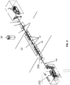
- Figure 1 illustrates an aircraft arresting system 10 with a cable 12 extending across the runway.
- Figure 2 illustrates the system of Figure 1 , along with runway edge sheaves 150 and brake systems/energy absorbers 152. These components are positioned alongside the runway for managing payout tape 154 that is secured to the cable 12 for a safe aircraft stop.
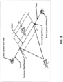
- Figure 3 illustrates a schematic view of an aircraft with a tailhook engaging a cross-runway pendant cable 12.
- retraction mechanisms 14 mounted below the runway surface. Operation of the retraction mechanisms 14 takes place from a control tower system 16 or a control system located off the runway near the arresting system, depending upon fight operations and requirements.
- the present inventors have designed an arresting retraction system that decouples the motion actuator used to lower the cable below the runway surface from components associated with deflection due to rollover. Decoupling these components helps isolate the motion actuator and related components from the dynamic loading associated with a rollover event. This allows the presently disclosed system to withstand high speed and high frequency rollover events, extending the life and operational envelope of the motion actuator and the system as a whole.
- an arresting cable retraction system for securing a cross-runway cable across an aircraft runway, comprising: a cable support block assembly configured to receive a cross-runway cable; a support arm assembly, the cable support block assembly being releasably secured to the support arm assembly, the support arm assembly comprising: a first axis of rotation about which the support arm assembly is configured to rotate during an aircraft rollover event, such that the cable is maintained above the runway; and a second axis of rotation about which the cable support block assembly is configured to rotate during a retraction event, such that the cable is retracted into a runway trough.
- the cable support block assembly comprises a lock mechanism that secures the support block assembly to the support arm assembly, wherein when the lock mechanism is locked, the support arm assembly is configured to rotate about the first axis of rotation upon aircraft wheel pressure to the cable support block assembly.
- the system also comprises a retraction arm assembly, wherein the retraction arm assembly functions to release the lock mechanism to decouple the support block assembly from the support arm assembly, and wherein when the lock mechanism is unlocked, the support arm is configured to remain stationary and the support block assembly is configured to rotates about the second axis of rotation to retract the cable into the runway trough.
- the support arm assembly can have a main shaft that functions as the first axis of rotation, and the retraction arm may have a support block shaft that functions as the second axis of rotation. 14.
- the arresting cable retraction system may be positioned in a support box that comprises a top cover with a cable relief indentation.
- the support arm may have one or more lock blocks that receive a lock pin in order to secure the support block assembly to the support arm assembly.
- the support arm may also be provided a retraction arm and a motion actuator, wherein the motion actuator is operably coupled to the retraction arm assembly.
- the motion actuator may be coupled to a latch lock via a cable.
- a movable trolley may be provided, wherein when the movable trolley is in a first position, the cable support block is permitted to rotate with respect to the movable trolley, wherein when the movable trolley is in a second position, the cable support block is prevented from rotation with respect to the movable trolley.
- a modular cable support clock for an arresting cable retraction system for securing a cross-runway cable across an aircraft runway, comprising: a modular support block defining an opening for receiving a cross-runway cable; a housing configured to receive the modular support block, wherein the modular support block is removeably secured with respect to the housing; and a lock mechanism that secures the modular support block with respect to the housing.
- the removable securement is achieved via insert grooves positioned along one of the modular support block or the housing that cooperate with tracks positioned on the other of the modular support block or the housing.
- Arresting cable retraction mechanisms are generally designed to raise and lower a cross-runway cable above and below an aircraft runway.
- the mechanisms should also be capable of withstanding rollover by aircraft tires.
- the present disclosure provides an arresting cable retraction mechanism that decouples the retraction components from the components that experience the force from an aircraft rollover. This provides a more robust system that can withstand higher aircraft speeds while requiring reduced maintenance.
- arresting cable retraction mechanism systems are often left in the battery position (i.e., a raised and engagement ready position), which exposes the system to frequent impacts due to aircraft rollovers.
- the frequency of impacts due to rollovers can result in damage to the actual retraction components, can prevent the retraction mechanism from operating reliably, or can require additional servicing or repairs of the system.
- the present inventors realized that it is desirable to provide a system that more effectively absorbs and distributes the forces of frequent high-speed aircraft rollovers.
- a stronger and more robust mechanism has been developed.
- the increased robustness of the disclosed system can help decrease maintenance costs and keep maintenance personnel off of active runways and out of danger during flight operations due to fewer required maintenance actions.
- the system is also more effective at absorbing and distributing the forces of frequent high-speed aircraft rollovers, increasing operability and reliability while decreasing time spent on maintenance.
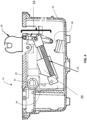
- a BAK-14M the most common current arresting cable retraction mechanism 14 in use is referred to as a BAK-14M, one example of which is shown in Figures 4-6 .
- This mechanism 14 consists of a single assembly, called a support arm 18, which is mounted to a cover plate 20 and that rests within a support box 22.
- the support box 22 is mounted below the runway surface, and the cover plate 20 is flush with the runway surface.
- the support arm 18 includes components required for the retraction process, including a linkage assembly 24 and a motion actuator 26.
- the support arm 18 also includes a cable support block 30, which extends above the support box 22 and is used to secure a cross-runway cable above the runway.
- Figure 4 illustrates the cable support block 30 in a cable raised position.
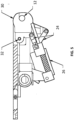
- Actuation of the motion actuator 26 causes retraction movement of the linkage assembly 24 (which is generally formed as two toggle links as shown), which moves the cable support block about a pivot point 32, retracting the cable support block 30 as illustrated by Figure 5 . This action will occur when the cable support block should be retracted into the runway trough.
- a torsion spring 34 is provided along a support arm shaft that adds deflection capability of the support arm 18.
- the support arm, which carries the motion actuator 26, moves down to impact the down stop bumper 28.
- the torsion spring 34 may also help absorb impact energy.
- a compression spring 36 helps return the linkage assembly 24 and the motion actuator 26 to their battery position.
- the described embodiments thus provide an arresting cable retraction system 40 that separates the retraction assembly arm from the rollover/deflection components.
- the retraction assembly arm supports the components that raise the system's cable support block in order to position the pendant cable in its battery position above the runway and which lower the system cable support block and cable to its retracted position in order to position them the either flush or below the with runway or in a retracted position within a trough of the runway.
- the deflection components support the components that allow the cable support block to lower during a rollover event but spring back up to its ready position as soon the aircraft wheels have passed. Separating the system components from one another provides a more robust and reliable system.
- the system 40 may be contained within a support box 22 that is mounted below a runway surface. It is possible for the disclosed system 40 to be used with a currently-installed (and/or prior art) support box 22, such that the system 40 is retrofittable. This allows the system 40 to be installed into an existing retraction mechanism installation without the need for additional runway civil work or extensive excavation efforts. Existing electrical power, motion control, and/or sensing capabilities of an existing system may be used without modification.
- Figure 7 shows a support box 22 mounted with respect to an aircraft runway surface 48.
- the runway 48 is designed with a trough 50 that extends the length of the runway surface 48.
- retraction mechanism system components may be used to lower the cable 12 into the trough 50.
- the cable 12 When in a raised position, the cable 12 extends through a cable support block 44. When in a lowered position, the cable support block 44 is retracted/rotated forward such that the cable 12 can be received into the trough 50.
- the system 40 operates in three primary positions.
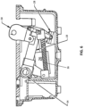
- Figure 8 illustrates the system 40 in the battery position, which is the system in a raised position.
- the cross-runway cable will be mounted within the support block 44 above the runway surface and is ready for an aircraft tailhook engagement if needed.
- Figure 9 illustrates the support arm assembly 52 of the system 40.
- Figure 10A illustrates a close up view of the support arm 52 in a locked configuration.
- Figures 10B and 11 illustrate the system support arm 52 in the rollover position, which is the system in the deflected position.
- This position is achieved when an aircraft tire impacts the support block 44, causing the assembly to deflect and rotate under load in order to absorb the impact energy.
- the cross-runway cable remains above the runway surface. Not allowing the cross-runway cable 12 to recede below the runway surface, even in this deflected position, helps prevent a hook skip. (A hook skip is the failure of the aircraft to engage the cable when needed.)
- Figure 12 illustrates the retraction assembly 68 of the system 40.
- Figure 13 illustrates a midway step in the retraction of the system 40
- Figure 14 illustrates the system in a fully retracted configuration.
- the cross runway cable 12 lies beneath the cover plate 20 (which is flush with the aircraft runway surface 48) and can be positioned within the trough, creating an obstruction-free runway. This position may be used when the runway is not in use by tailhook equipped aircraft and the cable is not required to be accessible.
- the movement of the cable support block 44 is controlled via a support arm assembly 52, illustrated by FIGS. 9 and 10 , and a retraction assembly 68, illustrated by FIG. 12 . These components work together in order to cause the described types of movement of the cable support block 44, and consequent movement of the cross-runway cable 12.
- Figures 9 and 10 illustrate the support arm assembly 52, which is also shown in combination with other system components by FIGS. 11 and 13-14 .
- the support arm assembly 52 contains multiple axes of rotation.
- a first axis of rotation 54 provides for rotation of the support arm assembly 52 during rollover (illustrated by Figures 10B-11 ). This first axis 54 allows the support arm 52, including the cable support block 44, to absorb the energy applied during rollover impact.
- a second axis of rotation 56 provides for rotation of the cable support block 44 and its related components (which may be referred to collectively as a support block assembly 80 as illustrated by FIG. 15 ) during retraction (illustrated by Figures 13-14 ). This second axis 56 allows the support block assembly 80 to rotate below the surface of the runway. Providing these two different axes of rotation prevents the retraction components from receiving excessive force during high-speed rollovers. The functioning of these different axes of rotation will be described in more detail below.
- the support arm assembly 52 may be secured to a cable support block assembly 80.
- the cable support block assembly 80 includes a cable support block 44 with a cable receiving opening 58. This opening 58 receives and supports a cross-runway cable 12 in use, as shown by Figure 7 .
- the cable support block assembly 80 also includes a housing 82 which supports a lock mechanism 66 and a retention plate 88.
- Figure 15 illustrates one embodiment in which these components of a cable support block assembly 80 are modular and is described in more detail below. It should be understood however, that modularity is not required.
- the lock mechanism 66 may be defined by side lock blocks 160 on the support arm assembly 52 and a lock pin 162 of the housing of the support block assembly 80.
- lock blocks 160 are provided with a curved rear face 164 that is configured to receive the lock pin 162.
- the support block assembly 80 is rigidly secured to and moves with the support arm assembly 52. This collective movement is illustrated by the rollover event shown in FIGS. 10A and 11 .
- the support arm assembly 52 also has a main shaft 60 which defines the first axis of rotation 54.
- Associated with the main shaft are one or more rollover torsion springs 62.
- the main shaft 60 and the one or more rollover torsion springs 62 to provide the support arm assembly 52 with the ability to be deflected into the support box 22, as shown by Figures 10B and 11 during a rollover event.
- the one or more rollover torsion springs are wound around the main shaft 60.
- the spring(s) 62 may have rear supports 63 that extend generally parallel to a support box cover plate 20.
- the rear supports 63 help provide a counter lever support against the cover plate 20 during rotation of the support arm assembly 52 about the main shaft 60. This is illustrated by Figure 11 .
- the lock pin 162 is engaged, such that the support block assembly 80 and the support arm 52 are secured to one another and move as a single unit.
- the cable support block 44 When rollover pressure is applied to the cable support block 44 (e.g., in the form of force from aircraft wheels), it causes the support arm assembly 52 to rotate down and pivot with respect to the main shaft 60, moving from the position illustrated by Figures 9 and 10A to the position illustrated by FIGS. 10B and 11 .
- the cable support block 44 is depressed downwardly with respect to the cover plate 20, such that it lowers partially into the support box 22.
- the main shaft 60 is positioned in the rear of the support arm assembly 52.
- the torsion springs 62 absorb some of the energy of the aircraft wheel pressure.
- the cable 12 does not rotate into the trough because the support block 44 and its related components (assembly (80) is restrained from rotating with respect to any other components of the support arm assembly 52 by the locking mechanism 66.
- the geometry is such that as the support arm 52 rotates on axis 54 during a rollover, and the support block is prevented from pivoting on axis 56 due to the lock between the support block assembly 80 and the support arm assembly 52.
- the cable 12 can come down flush on the top cover 20 and there is insufficient arc for the cable to get pushed into the trough.
- the stop defined by the support arm 52 abutment members 166 and the downstop bumpers 78 can also help prevent the cable 12 from retracting further.
- the described deflected configuration is only maintained upon pressure from the aircraft wheels during the rollover.
- the torsion spring(s) 62 absorb a portion of the rollover force. Once pressure from the rollover wheel force is released from the cable support block 44, potential energy of the torsion spring 62 causes the support arm assembly 52 (with the locked cable support block assembly 80) to spring back up to the battery position of FIGS. 9 and 10A . This ensures that the cable support block 44 supporting the cable 12 is back up in time to present the cable 12 to an aircraft tailhook if necessary.
- This spring release can be analogized to the metal spikes positioned along one way entry barrier. Once the wheels of a vehicle have rolled over the spikes, they are allowed to spring back up into their ready position.
- the second axis of rotation 56 of the support arm assembly 52 is used for retraction. This is the process of retracting the cable support block 44 entirely below the runway surface 48 and into the trough 50 for storage or non-use. This is distinct from the rollover deflection described above.
- the second axis of rotation 56 is defined by a support block shaft 70.
- the support block shaft 70 is associated with one or more a support block torsion springs 72.
- the support block shaft 70 is the pivot shaft for the support block assembly 80 during retraction. When retraction is to occur, the lock mechanism 66 between the support block assembly 80 and the support arm assembly 52 is released, as described in more detail further below.
- the retraction arm assembly 68 is provided with a motion actuator 74 and a retraction arm 76.
- the retraction arm assembly 68 is also provided with one or more downstop bumpers 78, which are as described above.
- the motion actuator 74 may be a pneumatic actuator, a mechanical actuator, or any other type of motion actuator that may be used to raise and lower the system 40.
- the retraction arm assembly 68 does not move during rollover deflection but does provide some dampening to abutment members 166 through the downstop bumpers 78.
- the retraction arm assembly 68 is activated only during retraction of the support block assembly 80, which functions to move the cable 12 into the trough 50.
- the retraction arm 76 disengages the lock mechanism 66 of the support arm assembly 52.
- actuation of the motion actuator 74 moves the retraction arm 76 from its released/disengaged position (of Figures 11 and 12 ) to its engaged position of Figure 13 and 14 .
- the retraction arm 76 applies pressure to the lock pin 162 in order to force the lock pin 162 out of the curved face 164 of the lock blocks 60. Release of lock pin 162 decouples the cable support block assembly 80 from the support arm assembly 52. Independent rotation of the cable support block assembly 80 about the second axis 56 allows its retraction.
- the retraction arm 76 works against upward pressure from the torsion springs 72 to pull/pivot the cable support block assembly 80 about the support block shaft 70/second axis 56 into the retracted position, as illustrated by FIG. 14 .
- the lock mechanism 66 thus enables the system 40 to have multiple axis of rotation, while only using the one required for a particular operation.
- the cable support block assembly 80 and the support arm assembly 52 are locked to one another such that the support arm assembly absorbs the energy of a rollover.
- the cable support block assembly 80 is permitted to pivot with respect to the support arm assembly such that the motion actuator 74 and the retraction arm 78 of the retraction assembly retracts the support block assembly 80 (and the cable contained within it) into the support box 22 in order to clear the runway surface.
- the support arm assembly 52 is able to rotate on the main shaft 60/first axis 54 for rollover deflection.
- the locked configuration does not transmit any force to the motion actuator 74 or the retraction arm 76 of the retraction arm assembly 68, preventing them from experiencing impact loading imparted by high-speed rollover forces.
- the lock mechanism 66 is disengaged by the retraction arm 76, the cable support block assembly 80 is allowed to rotate with respect to the support block shaft 70/second axis 56 by the continued motion of the retraction arm 76, in order to move the cable support block assembly 80 into a lowered position.
- Figure 15 illustrates a modular option for a modular cable support block system 80, and shows the below described components in an exploded view. It should be understood, however, that these components may be formed as a single component if desired.
- the modular version allows for quick and easy replacement of the support block 85 itself without requiring replacement of the support block housing 82 or any other system components. This can be useful because the cable support block is the system component that has the potential to receive the most damage due to aircraft wheel rollover.
- the modular system of Figure 15 may be provided.
- the modular support block 85 may be secured with respect to housing 82 via insert grooves 84 that are positioned along the base of the modular support block 85 that cooperate with corresponding tracks 86 of the housing.
- module support block 85 may be removably secured to the housing 82. It may be removed and replaced if needed without removing the entire system from the support box.
- Figure 15 also illustrates the lock mechanism, shown as a lock plate 88, that secures the modular support block 85 to the housing 82.
- the lock plate 88 is secured with respect to the cable support block housing 82.
- the lock plate 88 may be removed, and the support block may slide out from the housing 82.
- the lock mechanism 66 is shown and described as a rod restrained within a slot on the support arm assembly 52 that maintains its position in the locked position via springs that force it into a curved face 164 of the lock block 160.
- the locking functionality can be achieved using designs that include pins, keys, actuating components, slides, etc. and should not be limited to specific lock mechanism described.
- the general concept is to maintain the support block assembly 80 in a secured position with respect to the support arm assembly 52 in order to prevent aircraft wheel rollover forces applied to the cable support block assembly 85 from extending to the motion actuator components contained in the retraction assembly 68.
- the motion actuator 74 When the tower or site wishes to raise the system back up to the battery position, the motion actuator 74 extends, releasing the retraction arm 76 from the lock mechanism 66.
- the support block torsion spring(s) 72 located on the support block shaft 70 provide the force to return the cable support block assembly 85 to the battery position. This also re-engages the spring loaded lock mechanism 66 so that the system is in position for an aircraft rollover event. Both lock mechanism disengagement and support block retraction is accomplished using the motion of the retraction actuator 74 and retraction arm 76, of the retraction arm assembly 68.
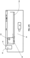
- FIGS. 17A-C and 18 illustrate an alternate embodiment of a retraction/rollover mechanism 90.
- the system of these figures also provides two axes of rotation for the support block 44.
- a first axis of rotation 96 is for a latch lock 92.
- the latch lock 92 pivots about this axis 96 until it comes in contact with a latch plate 104, which stops it from rotating further.
- the support block 44 rotates about a second axis 180. This rotation causes the support block 44 to retract into the trough, as illustrated by FIGS. 17A-C .
- a third axis of rotation 98 allows the support block 44 to experience rollover without impacting the motion actuator 74, which may be a pneumatic cylinder or any other appropriate type of actuator.
- Figure 17A illustrates the retraction/rollover mechanism 90 in its raised and locked position, holding a pendant cable 12 in a battery position.
- the support block 44 has a latch lock 92.
- the latch lock 92 is translatable between an upright locked position ( Figure 17A ) and a translated unlocked position ( Figure 17B ). Movement between the locked and unlocked position is managed via a cable 94 (which may also be a cord, a wire, a link, or other type of retractable mechanism that can couple the latch lock 92 to a motion actuator 74).
- a cable 94 which may also be a cord, a wire, a link, or other type of retractable mechanism that can couple the latch lock 92 to a motion actuator 74.
- One end of the cable 94 is secured to the latch lock 92 and a second end of the cable 94 is secured to the motion actuator 74.
- Figure 18 illustrates the mechanism 90 during a rollover event.
- the movement of the cable support block 44 occurs with respect to the third axis 98.
- Third axis 98 is defined by a main shaft 100 about which there is positioned a torsion spring 101.
- the latch lock 92 remains locked with respect to the cable support block 44, such that the second axis 108 of rotation is locked and not available.
- the only available axis for rotation is the third axis 98 (rotation about the main shaft 100). Accordingly, during a rollover event, pressure against the cable support block 44 causes the main shaft 100 to pivot and the support arm 102 to rotate downwardly, as shown by Figure 18 .
- the cable 94 is somewhat flexible, it does not transfer this downward load to the motion actuator 74. This separates the retraction mechanism components from the rollover mechanism components, such that the retraction mechanism components do not experience force or load transmitted during rollover. In short, the retraction motion and the rollover motion are in different, separate paths.
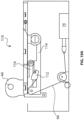
- FIGs 19A-19B and 20 illustrate an alternate embodiment of a retraction/rollover mechanism 110.
- This mechanism also uses a motion actuator 74 and a cable 94 for retraction of the cable support block 44.
- One end of the cable 94 is secured to the motion actuator 74, and one end of the cable is secured to a hook arm of the lock mechanism 112.
- activation of the motion actuator 74 causes a pull force applied to the cable 94, which releases a lock mechanism 112 that secures a support arm 114 to a roller arm 116. Release of lock mechanism 112 disengages the roller arm 116 from the support arm, as illustrated by Figure 19B .
- Figure 20 illustrates the mechanism 110 during a rollover event.
- the support arm 114 remains locked to the roller arm 116 via the lock mechanism 112. (This is because the cable 94 is not pulled by the motion actuator 74 so it does not cause release of the lock mechanism 112 from pin 113.)
- the support arm pivots at the second axis 126. This pivoting does not translate any force to the motion actuator 74. Instead, in this version, only the support arm 114 rotates with respect to the second axis 126.
- the first axis 124 remains locked and is unavailable for rotation thereabout.
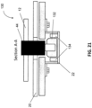
- FIGS 21 , 22A-22B , and 23 illustrate a retraction/rollover mechanism 130 that uses a rolling or sliding trolley 132.
- Figures 21 and 22A show the mechanism in battery position.
- the retraction position is shown in Figure 22B .
- Figure 23 is the rollover position.
- a trolley 132 may be provided with one or more wheels 134 that allow the trolley 132 to roll with respect to the support frame 22.
- This embodiment provides a cable 94 with one end that is secured to the cable support block 44 and another end that is secured to the trolley 132.
- movement of the trolley 132 is caused by a motion actuator 74.
- Figure 23 illustrates the mechanism 130 during a rollover event.
- the trolley 132 is not moved via the motion actuator 74, such that it remain stationary. This allows the trolley 132 to primarily function as a lock, preventing the cable support block from rotating with respect to the first axis 138 support block engagement roller 136. Instead, pressure on the cable support block 44 causes downward deflection movement of an arm 140 that may be pivotally secured to the motion actuator 74 at a second axis 142. The cable support block is not permitted to rotate with respect to the first axis 138 due to the location of the trolley 132. Instead, downward movement of the arm 140 allows downward movement of the cable support block 44.
- the arresting cable retraction mechanism provides one axis of rotation for the rollover event, and a second, separate axis of rotation for the retraction event. This prevents the motion actuator from absorbing the force from the rollover. Instead, the motion actuator and its related components is mechanically isolated from force during a rollover event.
- the motion actuator is operably coupled to the cable support block during a retraction event only.
Landscapes
- Engineering & Computer Science (AREA)
- Mechanical Engineering (AREA)
- Aviation & Aerospace Engineering (AREA)
- Current-Collector Devices For Electrically Propelled Vehicles (AREA)
- Installation Of Indoor Wiring (AREA)
- Manipulator (AREA)
- Electric Cable Arrangement Between Relatively Moving Parts (AREA)
Description
- The field of this disclosure relates to an arresting cable retraction mechanism for use across an aircraft runway. The retraction mechanism functions to raise a cable above a runway (for capture by a tailhook of an aircraft) without causing the cable to recede below the runway surface during an aircraft rollover/deflection event. The arresting cable retraction mechanism is also designed to help prevent damage to a motion actuator due to high speed aircraft rollover. The disclosed system separates components related to retraction vs. deflection due to rollover, such that rollover events do not affect or load the motion actuator used for retraction and the mass of the system being deflected is minimized.
- One type of aircraft arresting system that is used to decelerate an aircraft functions by raising a cable across the runway. These systems are often installed on runways (commercial or military) where aircraft equipped with a tailhook may need to land. In use, the tailhook of the aircraft can engage the cable in order to bring the aircraft to a safe stop.
- One component of an
aircraft arresting system 10 is an arresting cable retraction mechanism. As shown byFigure 1 , these mechanisms are used to retract across-runway cable 12 into a trough that spans the runway below the runway surface in order to provide an obstruction-free runway when thecross-runway cable 12 is not in use. During flight operations, an arrestingcable retraction mechanism 14 raises thecable 12 to the battery (i.e., engagement ready) position. This position holds the cross-runway cable at the correct height above the runway to allow the tailhook of an aircraft to engage the cable connected to the aircraft arresting system, bringing the aircraft to a controlled and safe stop.Figure 1 illustrates anaircraft arresting system 10 with acable 12 extending across the runway.Figure 2 illustrates the system ofFigure 1 , along withrunway edge sheaves 150 and brake systems/energy absorbers 152. These components are positioned alongside the runway for managingpayout tape 154 that is secured to thecable 12 for a safe aircraft stop.Figure 3 illustrates a schematic view of an aircraft with a tailhook engaging across-runway pendant cable 12. - Referring back to
Figures 1 and2 , there are multipleindividual retraction mechanisms 14 mounted below the runway surface. Operation of theretraction mechanisms 14 takes place from acontrol tower system 16 or a control system located off the runway near the arresting system, depending upon fight operations and requirements. - Because these systems are installed on runways over which aircraft travel at high speeds, the
mechanisms 14 often experience impact loading from aircraft wheels during a rollover event. This means that the systems are consequently subject to frequent periodic maintenance. Current arresting cable retraction mechanisms available on the market are not designed to withstand the forces of a high-speed aircraft rollover. These mechanisms are typically only rated for rollovers of up to 25 knots. However, current military operating procedures dictate that an arresting cable retraction mechanism must be able to withstand rollover speeds in excess of 25 knots. Improvements to arresting cable retraction mechanisms are thus desirable.
US 6 394 390 B1 describes a hook cable support assembly arranged to support a hook cable above a runway surface for arrestment of an aircraft having a tail hook. - Accordingly, the present inventors have designed an arresting retraction system that decouples the motion actuator used to lower the cable below the runway surface from components associated with deflection due to rollover. Decoupling these components helps isolate the motion actuator and related components from the dynamic loading associated with a rollover event. This allows the presently disclosed system to withstand high speed and high frequency rollover events, extending the life and operational envelope of the motion actuator and the system as a whole.
- According to the invention, there is provided an arresting cable retraction system for securing a cross-runway cable across an aircraft runway, comprising: a cable support block assembly configured to receive a cross-runway cable; a support arm assembly, the cable support block assembly being releasably secured to the support arm assembly, the support arm assembly comprising: a first axis of rotation about which the support arm assembly is configured to rotate during an aircraft rollover event, such that the cable is maintained above the runway; and a second axis of rotation about which the cable support block assembly is configured to rotate during a retraction event, such that the cable is retracted into a runway trough. The cable support block assembly comprises a lock mechanism that secures the support block assembly to the support arm assembly, wherein when the lock mechanism is locked, the support arm assembly is configured to rotate about the first axis of rotation upon aircraft wheel pressure to the cable support block assembly. The system also comprises a retraction arm assembly, wherein the retraction arm assembly functions to release the lock mechanism to decouple the support block assembly from the support arm assembly, and wherein when the lock mechanism is unlocked, the support arm is configured to remain stationary and the support block assembly is configured to rotates about the second axis of rotation to retract the cable into the runway trough. Further embodiments of the invention are set out in the appended set of claims. The support arm assembly can have a main shaft that functions as the first axis of rotation, and the retraction arm may have a support block shaft that functions as the second axis of rotation. 14. The arresting cable retraction system may be positioned in a support box that comprises a top cover with a cable relief indentation.
- For locking the cable support assembly to the support arm assembly, the support arm may have one or more lock blocks that receive a lock pin in order to secure the support block assembly to the support arm assembly. There may also be provided a retraction arm and a motion actuator, wherein the motion actuator is operably coupled to the retraction arm assembly.
- In other examples, the motion actuator may be coupled to a latch lock via a cable. In a further example, a movable trolley may be provided, wherein when the movable trolley is in a first position, the cable support block is permitted to rotate with respect to the movable trolley, wherein when the movable trolley is in a second position, the cable support block is prevented from rotation with respect to the movable trolley.
- There may also be provided a modular cable support clock for an arresting cable retraction system for securing a cross-runway cable across an aircraft runway, comprising: a modular support block defining an opening for receiving a cross-runway cable; a housing configured to receive the modular support block, wherein the modular support block is removeably secured with respect to the housing; and a lock mechanism that secures the modular support block with respect to the housing. In some examples, the removable securement is achieved via insert grooves positioned along one of the modular support block or the housing that cooperate with tracks positioned on the other of the modular support block or the housing.
-
-
Figure 1 is a side perspective view of a cross-runway cable extending across an aircraft runway and being positioned via a series of arresting cable retraction mechanisms. -
Figure 2 illustrates the system ofFigure 1 with additional system components. -
Figure 3 illustrates a schematic view of an aircraft with a tailhook catching a cross-runway pendant cable. -
Figure 4 is a side plan view of a prior art arresting cable retraction mechanism, positioning the cable in a raised/battery/ready position. -
Figure 5 is a side plan view of the arresting cable retraction mechanism ofFigure 4 , positioning the cable in the retracted position. -
Figure 6 is a side plan view of the arresting cable retraction mechanism ofFigure 4 , positioning the cable in the rollover position. -
Figure 7 is a side perspective view of one embodiment of an arresting cable retraction system of this disclosure. -
Figure 8 is a side perspective view of an arresting cable retraction system in position within a support box, positioning the cable in a raised/battery/ready position. -
Figure 9 is a side perspective view of one embodiment of a support arm assembly for use in connection with the disclosed arresting cable retraction system. -
Figure 10A is a front perspective view of a cable support block assembly locked in position with respect to the support arm assembly. -
Figure 10B is a side plan view of movement of the cable support block assembly and support arm assembly during a rollover. -
Figure 11 is a side perspective view of movement of the cable support block assembly and support arm assembly during a rollover, also showing the location of a retraction arm assembly that is disengaged from the support arm assembly. -
Figure 12 is a top perspective view of one embodiment of a retraction arm assembly for use in connection with the disclosed arresting cable retraction system. -
Figure 13 illustrates a front perspective view of the retraction arm assembly engaging and releasing the lock mechanism, allowing retraction of the support block assembly with respect to the support arm assembly. -
Figure 14 shows a side perspective view of the disclosed arresting cable retraction system in a retracted position. -
Figure 15 shows an exploded view of one embodiment of a modular cable support block. -
Figure 16 shows a top perspective view of a cover plate with a scalloped cable-receiving portion. -
Figures 17A-17C show an alternate embodiment of a retraction/roller mechanism.Figures 17A and 17B show release of a latch lock.Figure 17C shows rotation of the support block into a retracted position. -
Figure 18 shows the mechanism ofFigures 17A-17C in a rollover position. -
Figures 19A-19B show an alternate embodiment of a retraction/roller mechanism.Figures 19A and19B show release of a lock mechanism via a cable and rotation of the support block into a retracted position. -
Figure 20 shows the mechanism ofFigures 19A-19B in a rollover position. -
Figure 21 shows a front plan view of a further embodiment of a retraction/roller mechanism. -
Figure 22A shows the mechanism ofFigure 21 in a raised/battery position.Figure 22B shows the mechanism ofFigure 21 in a retracted position. -
Figure 23 shows the mechanism ofFigures 22A-22B in a rollover position. - Arresting cable retraction mechanisms are generally designed to raise and lower a cross-runway cable above and below an aircraft runway. The mechanisms should also be capable of withstanding rollover by aircraft tires. The present disclosure provides an arresting cable retraction mechanism that decouples the retraction components from the components that experience the force from an aircraft rollover. This provides a more robust system that can withstand higher aircraft speeds while requiring reduced maintenance.
- During military operations, arresting cable retraction mechanism systems are often left in the battery position (i.e., a raised and engagement ready position), which exposes the system to frequent impacts due to aircraft rollovers. The frequency of impacts due to rollovers can result in damage to the actual retraction components, can prevent the retraction mechanism from operating reliably, or can require additional servicing or repairs of the system.
- Based on some of the above-described problems with current arresting cable retraction mechanisms, the present inventors realized that it is desirable to provide a system that more effectively absorbs and distributes the forces of frequent high-speed aircraft rollovers. A stronger and more robust mechanism has been developed. The increased robustness of the disclosed system can help decrease maintenance costs and keep maintenance personnel off of active runways and out of danger during flight operations due to fewer required maintenance actions. The system is also more effective at absorbing and distributing the forces of frequent high-speed aircraft rollovers, increasing operability and reliability while decreasing time spent on maintenance.
- As background, the most common current arresting
cable retraction mechanism 14 in use is referred to as a BAK-14M, one example of which is shown inFigures 4-6 . Thismechanism 14 consists of a single assembly, called asupport arm 18, which is mounted to acover plate 20 and that rests within asupport box 22. Thesupport box 22 is mounted below the runway surface, and thecover plate 20 is flush with the runway surface. Thesupport arm 18 includes components required for the retraction process, including alinkage assembly 24 and amotion actuator 26. Thesupport arm 18 also includes acable support block 30, which extends above thesupport box 22 and is used to secure a cross-runway cable above the runway.Figure 4 illustrates thecable support block 30 in a cable raised position. Actuation of themotion actuator 26 causes retraction movement of the linkage assembly 24 (which is generally formed as two toggle links as shown), which moves the cable support block about apivot point 32, retracting thecable support block 30 as illustrated byFigure 5 . This action will occur when the cable support block should be retracted into the runway trough. - When an aircraft rolls over the
cable support block 30, theentire support arm 18 deflects to the rollover position shown inFigure 6 . In this example, thesupport arm 18 is forced downwardly. Atorsion spring 34 is provided along a support arm shaft that adds deflection capability of thesupport arm 18. The support arm, which carries themotion actuator 26, moves down to impact thedown stop bumper 28. Thetorsion spring 34 may also help absorb impact energy. Acompression spring 36 helps return thelinkage assembly 24 and themotion actuator 26 to their battery position. Once the aircraft wheels have rolled over thesupport arm 18/cable block support 30, potential energy of thetorsion spring 34 returns thesupport arm 18/cable block support 30 back up to the raised position ofFigure 4 . - Incorporating the components required for the retraction process in association with the
support arm 18, which is also the component that deflects during a rollover event, can increase the mass of thesupport arm 18, which in turn can increase the force experienced by the retraction components (F=ma). Additionally, themotion actuator 26 and other retraction components experience the shock of every aircraft rollover event, further contributing to system damage. - Military procedures often require that the cross-runway cable be up and ready any time that an aircraft equipped with a tailhook is landing. Accordingly, the arresting cable retraction mechanism(s) potentially experience the force of aircraft wheels due to rollover during every landing. Also, during an aircraft rollover event, the inventors have identified that cross-runway cable should not move below the runway surface as it would during a retraction command. The cross-runway cable should remain above the runway surface during an aircraft rollover, in the event that a tailhook engagement is required. Failure of the cross-runway cable to maintain its position above the runway surface can create the possibility of a hook skip or failure of the aircraft tailhook to engage the arresting system entirely.
- The described embodiments thus provide an arresting
cable retraction system 40 that separates the retraction assembly arm from the rollover/deflection components. The retraction assembly arm supports the components that raise the system's cable support block in order to position the pendant cable in its battery position above the runway and which lower the system cable support block and cable to its retracted position in order to position them the either flush or below the with runway or in a retracted position within a trough of the runway. The deflection components support the components that allow the cable support block to lower during a rollover event but spring back up to its ready position as soon the aircraft wheels have passed. Separating the system components from one another provides a more robust and reliable system. - Referring now to
Figure 7 , thesystem 40 may be contained within asupport box 22 that is mounted below a runway surface. It is possible for the disclosedsystem 40 to be used with a currently-installed (and/or prior art)support box 22, such that thesystem 40 is retrofittable. This allows thesystem 40 to be installed into an existing retraction mechanism installation without the need for additional runway civil work or extensive excavation efforts. Existing electrical power, motion control, and/or sensing capabilities of an existing system may be used without modification.Figure 7 shows asupport box 22 mounted with respect to anaircraft runway surface 48. Therunway 48 is designed with atrough 50 that extends the length of therunway surface 48. When thesystem 40 is not in use, retraction mechanism system components (described in detail below) may be used to lower thecable 12 into thetrough 50. When in a raised position, thecable 12 extends through acable support block 44. When in a lowered position, thecable support block 44 is retracted/rotated forward such that thecable 12 can be received into thetrough 50. - The
system 40 operates in three primary positions.Figure 8 illustrates thesystem 40 in the battery position, which is the system in a raised position. The cross-runway cable will be mounted within thesupport block 44 above the runway surface and is ready for an aircraft tailhook engagement if needed.Figure 9 illustrates thesupport arm assembly 52 of thesystem 40.Figure 10A illustrates a close up view of thesupport arm 52 in a locked configuration.Figures 10B and11 illustrate thesystem support arm 52 in the rollover position, which is the system in the deflected position. This position is achieved when an aircraft tire impacts thesupport block 44, causing the assembly to deflect and rotate under load in order to absorb the impact energy. In this position, the cross-runway cable remains above the runway surface. Not allowing thecross-runway cable 12 to recede below the runway surface, even in this deflected position, helps prevent a hook skip. (A hook skip is the failure of the aircraft to engage the cable when needed.) -
Figure 12 illustrates theretraction assembly 68 of thesystem 40.Figure 13 illustrates a midway step in the retraction of thesystem 40, andFigure 14 illustrates the system in a fully retracted configuration. In this position, thecross runway cable 12 lies beneath the cover plate 20 (which is flush with the aircraft runway surface 48) and can be positioned within the trough, creating an obstruction-free runway. This position may be used when the runway is not in use by tailhook equipped aircraft and the cable is not required to be accessible. Reference will now be made to these figures and the components that coordinate the rollover event as distinct from the retraction event. - The movement of the
cable support block 44 is controlled via asupport arm assembly 52, illustrated byFIGS. 9 and10 , and aretraction assembly 68, illustrated byFIG. 12 . These components work together in order to cause the described types of movement of thecable support block 44, and consequent movement of thecross-runway cable 12. -
Figures 9 and10 illustrate thesupport arm assembly 52, which is also shown in combination with other system components byFIGS. 11 and13-14 . Thesupport arm assembly 52 contains multiple axes of rotation. A first axis ofrotation 54 provides for rotation of thesupport arm assembly 52 during rollover (illustrated byFigures 10B-11 ). Thisfirst axis 54 allows thesupport arm 52, including thecable support block 44, to absorb the energy applied during rollover impact. A second axis ofrotation 56 provides for rotation of thecable support block 44 and its related components (which may be referred to collectively as asupport block assembly 80 as illustrated byFIG. 15 ) during retraction (illustrated byFigures 13-14 ). Thissecond axis 56 allows thesupport block assembly 80 to rotate below the surface of the runway. Providing these two different axes of rotation prevents the retraction components from receiving excessive force during high-speed rollovers. The functioning of these different axes of rotation will be described in more detail below. - Referring more specifically to
Figure 9 , thesupport arm assembly 52 may be secured to a cablesupport block assembly 80. The cablesupport block assembly 80 includes acable support block 44 with acable receiving opening 58. Thisopening 58 receives and supports across-runway cable 12 in use, as shown byFigure 7 . The cablesupport block assembly 80 also includes ahousing 82 which supports alock mechanism 66 and aretention plate 88. (Figure 15 illustrates one embodiment in which these components of a cablesupport block assembly 80 are modular and is described in more detail below. It should be understood however, that modularity is not required.) As illustrated byFIG. 10A , thelock mechanism 66 may be defined by side lock blocks 160 on thesupport arm assembly 52 and alock pin 162 of the housing of thesupport block assembly 80. As illustrated byFigures 10A and 10B , lock blocks 160 are provided with a curved rear face 164 that is configured to receive thelock pin 162. When thelock pin 162 is engaged in the side lock blocks 160 as shown, thesupport block assembly 80 is rigidly secured to and moves with thesupport arm assembly 52. This collective movement is illustrated by the rollover event shown inFIGS. 10A and11 . - Referring back to
Figure 9 , thesupport arm assembly 52 also has amain shaft 60 which defines the first axis ofrotation 54. Associated with the main shaft are one or more rollover torsion springs 62. Themain shaft 60 and the one or more rollover torsion springs 62 to provide thesupport arm assembly 52 with the ability to be deflected into thesupport box 22, as shown byFigures 10B and11 during a rollover event. The one or more rollover torsion springs are wound around themain shaft 60. The spring(s) 62 may haverear supports 63 that extend generally parallel to a supportbox cover plate 20. The rear supports 63 help provide a counter lever support against thecover plate 20 during rotation of thesupport arm assembly 52 about themain shaft 60. This is illustrated byFigure 11 . In this figure, thelock pin 162 is engaged, such that thesupport block assembly 80 and thesupport arm 52 are secured to one another and move as a single unit. - When rollover pressure is applied to the cable support block 44 (e.g., in the form of force from aircraft wheels), it causes the
support arm assembly 52 to rotate down and pivot with respect to themain shaft 60, moving from the position illustrated byFigures 9 and10A to the position illustrated byFIGS. 10B and11 . Thecable support block 44 is depressed downwardly with respect to thecover plate 20, such that it lowers partially into thesupport box 22. Themain shaft 60 is positioned in the rear of thesupport arm assembly 52. The torsion springs 62 absorb some of the energy of the aircraft wheel pressure. Pivoting about thefirst axis 54 continues until theabutment members 166 of thesupport arm assembly 52 contact thedownstop bumper 78 located on the retraction assembly 68 (Figure 12 illustrates theretraction assembly 68 on its own, and will be described in more detail below). It is important to note that during a rollover event, thecable 12 does not retract into thetrough 50. Instead, it remains above the runway surface, as illustrated by the rollover position ofFIG. 11 . In prior art systems, there has been the possibility that the cable could catch in the trough and not be in battery position during a tailhook event. However, in this disclosed system, thecable 12 does not rotate into the trough because thesupport block 44 and its related components (assembly (80) is restrained from rotating with respect to any other components of thesupport arm assembly 52 by thelocking mechanism 66. The geometry is such that as thesupport arm 52 rotates onaxis 54 during a rollover, and the support block is prevented from pivoting onaxis 56 due to the lock between thesupport block assembly 80 and thesupport arm assembly 52. Thecable 12 can come down flush on thetop cover 20 and there is insufficient arc for the cable to get pushed into the trough. The stop defined by thesupport arm 52abutment members 166 and thedownstop bumpers 78 can also help prevent thecable 12 from retracting further. - In one example, it is possible to provide a scalloped shape along the
cable 12 where it impacts thecover plate 20 of thesupport box 22. In another example, it is possible to provide ascalloped shape 168 along thecover plate 20, in order to provide an area for thecable 12 to rest. One example is illustrated byFigure 16 . This cable relief indentation may alleviate damage caused by a scissoring motion between thecable 12 and thecover plate 20 during an aircraft rollover. - The described deflected configuration is only maintained upon pressure from the aircraft wheels during the rollover. The torsion spring(s) 62 absorb a portion of the rollover force. Once pressure from the rollover wheel force is released from the
cable support block 44, potential energy of thetorsion spring 62 causes the support arm assembly 52 (with the locked cable support block assembly 80) to spring back up to the battery position ofFIGS. 9 and10A . This ensures that thecable support block 44 supporting thecable 12 is back up in time to present thecable 12 to an aircraft tailhook if necessary. This spring release can be analogized to the metal spikes positioned along one way entry barrier. Once the wheels of a vehicle have rolled over the spikes, they are allowed to spring back up into their ready position. - Reference will now be made to
Figures 12-14 in order to describe retraction of thecable support block 40. Retraction occurs along the second axis ofrotation 56 of thesupport arm assembly 52. During retraction, the cablesupport block assembly 80 is unlocked or otherwise released from thesupport arm assembly 52 via release of thelock mechanism 66. Retraction moves the cablesupport block assembly 80 but not thesupport arm assembly 52. Thesupport arm assembly 52 remains stationary and does not pivot or rotate about thefirst axis 54 within thesupport box 22 during retraction. The second axis ofrotation 56 allows movement of thesupport block assembly 80 with respect to thesupport arm assembly 52. A comparison between the rollover configuration ofFigure 11 and the retraction configuration ofFigure 14 helps illustrate which axis of rotation is active. - The second axis of
rotation 56 of thesupport arm assembly 52 is used for retraction. This is the process of retracting thecable support block 44 entirely below therunway surface 48 and into thetrough 50 for storage or non-use. This is distinct from the rollover deflection described above. As shown byFigure 9 , the second axis ofrotation 56 is defined by asupport block shaft 70. Thesupport block shaft 70 is associated with one or more a support block torsion springs 72. Thesupport block shaft 70 is the pivot shaft for thesupport block assembly 80 during retraction. When retraction is to occur, thelock mechanism 66 between thesupport block assembly 80 and thesupport arm assembly 52 is released, as described in more detail further below. - Referring now to
FIG. 12 , theretraction arm assembly 68 is provided with amotion actuator 74 and aretraction arm 76. Theretraction arm assembly 68 is also provided with one ormore downstop bumpers 78, which are as described above. Themotion actuator 74 may be a pneumatic actuator, a mechanical actuator, or any other type of motion actuator that may be used to raise and lower thesystem 40. Theretraction arm assembly 68 does not move during rollover deflection but does provide some dampening toabutment members 166 through thedownstop bumpers 78. Theretraction arm assembly 68 is activated only during retraction of thesupport block assembly 80, which functions to move thecable 12 into thetrough 50. - When a retraction command is issued (e.g., which may be from the control tower 16), the
retraction arm 76 disengages thelock mechanism 66 of thesupport arm assembly 52. As illustrated byFigures 12-13 , actuation of themotion actuator 74 moves theretraction arm 76 from its released/disengaged position (ofFigures 11 and12 ) to its engaged position ofFigure 13 and14 . Theretraction arm 76 applies pressure to thelock pin 162 in order to force thelock pin 162 out of the curved face 164 of the lock blocks 60. Release oflock pin 162 decouples the cablesupport block assembly 80 from thesupport arm assembly 52. Independent rotation of the cablesupport block assembly 80 about thesecond axis 56 allows its retraction. After thelock mechanism 66 is disengaged, theretraction arm 76 works against upward pressure from the torsion springs 72 to pull/pivot the cablesupport block assembly 80 about thesupport block shaft 70/second axis 56 into the retracted position, as illustrated byFIG. 14 . Thelock mechanism 66 thus enables thesystem 40 to have multiple axis of rotation, while only using the one required for a particular operation. When in a locked configuration, the cablesupport block assembly 80 and thesupport arm assembly 52 are locked to one another such that the support arm assembly absorbs the energy of a rollover. When thelock mechanism 66 is in an unlocked configuration, the cablesupport block assembly 80 is permitted to pivot with respect to the support arm assembly such that themotion actuator 74 and theretraction arm 78 of the retraction assembly retracts the support block assembly 80 (and the cable contained within it) into thesupport box 22 in order to clear the runway surface. - For example, when the
lock mechanism 66 is engaged in a locked configuration (and theretraction arm 76 is disengaged), thesupport arm assembly 52 is able to rotate on themain shaft 60/first axis 54 for rollover deflection. The locked configuration does not transmit any force to themotion actuator 74 or theretraction arm 76 of theretraction arm assembly 68, preventing them from experiencing impact loading imparted by high-speed rollover forces. When thelock mechanism 66 is disengaged by theretraction arm 76, the cablesupport block assembly 80 is allowed to rotate with respect to thesupport block shaft 70/second axis 56 by the continued motion of theretraction arm 76, in order to move the cablesupport block assembly 80 into a lowered position. - These multiple points of rotation allow the
system 40 to absorb the aircraft rollover energy and retract the system using two unique motion paths. This is necessary in order to ensure that thecable 12 does not recede into therunway trough 50 during an aircraft rollover. This is also necessary in order to ensure that a rollover event does not damage themotion actuator 74 andretraction arm 76. Accordingly, themotion actuator 74 andretraction arm 76 remain stationary (along with the retraction arm assembly 68) during a deflection rollover event. -
Figure 15 illustrates a modular option for a modular cablesupport block system 80, and shows the below described components in an exploded view. It should be understood, however, that these components may be formed as a single component if desired. The modular version allows for quick and easy replacement of thesupport block 85 itself without requiring replacement of thesupport block housing 82 or any other system components. This can be useful because the cable support block is the system component that has the potential to receive the most damage due to aircraft wheel rollover. In order to exchange thecable support block 85 without removing the remainder of the components, the modular system ofFigure 15 may be provided. For example, themodular support block 85 may be secured with respect tohousing 82 viainsert grooves 84 that are positioned along the base of themodular support block 85 that cooperate withcorresponding tracks 86 of the housing. These components could be reversed so that the cooperation is vice versa. It is possible to dovetail/slide thecomponents modular support block 80 with respect to thehousing 82. The general concept is that themodule support block 85 may be removably secured to thehousing 82. It may be removed and replaced if needed without removing the entire system from the support box. -
Figure 15 also illustrates the lock mechanism, shown as alock plate 88, that secures themodular support block 85 to thehousing 82. Thelock plate 88 is secured with respect to the cablesupport block housing 82. For removal of themodular support block 85, thelock plate 88 may be removed, and the support block may slide out from thehousing 82. - In the described invention, the
lock mechanism 66 is shown and described as a rod restrained within a slot on thesupport arm assembly 52 that maintains its position in the locked position via springs that force it into a curved face 164 of thelock block 160. However, the locking functionality can be achieved using designs that include pins, keys, actuating components, slides, etc. and should not be limited to specific lock mechanism described. The general concept is to maintain thesupport block assembly 80 in a secured position with respect to thesupport arm assembly 52 in order to prevent aircraft wheel rollover forces applied to the cablesupport block assembly 85 from extending to the motion actuator components contained in theretraction assembly 68. - When the tower or site wishes to raise the system back up to the battery position, the
motion actuator 74 extends, releasing theretraction arm 76 from thelock mechanism 66. The support block torsion spring(s) 72 located on thesupport block shaft 70 provide the force to return the cablesupport block assembly 85 to the battery position. This also re-engages the spring loadedlock mechanism 66 so that the system is in position for an aircraft rollover event. Both lock mechanism disengagement and support block retraction is accomplished using the motion of theretraction actuator 74 andretraction arm 76, of theretraction arm assembly 68. -
Figures 17A-C and18 illustrate an alternate embodiment of a retraction/rollover mechanism 90. As with the above discussed system, the system of these figures also provides two axes of rotation for thesupport block 44. A first axis ofrotation 96 is for alatch lock 92. Thelatch lock 92 pivots about thisaxis 96 until it comes in contact with alatch plate 104, which stops it from rotating further. At that point, thesupport block 44 rotates about asecond axis 180. This rotation causes thesupport block 44 to retract into the trough, as illustrated byFIGS. 17A-C . Referring now toFigure 18 , a third axis ofrotation 98 allows thesupport block 44 to experience rollover without impacting themotion actuator 74, which may be a pneumatic cylinder or any other appropriate type of actuator. -
Figure 17A illustrates the retraction/rollover mechanism 90 in its raised and locked position, holding apendant cable 12 in a battery position. In this example, thesupport block 44 has alatch lock 92. As illustrated by the transition betweenFigure 17A and 17B , thelatch lock 92 is translatable between an upright locked position (Figure 17A ) and a translated unlocked position (Figure 17B ). Movement between the locked and unlocked position is managed via a cable 94 (which may also be a cord, a wire, a link, or other type of retractable mechanism that can couple thelatch lock 92 to a motion actuator 74). One end of thecable 94 is secured to thelatch lock 92 and a second end of thecable 94 is secured to themotion actuator 74. When themotion actuator 74 is activated, thecable 94 is pulled, which consequently pulls thelatch lock 92 in order to cause its translation. Release of the lockinglatch 92 then allows further retraction of thecable 94 via the motion actuator, which pulls/rotates thecable support block 44 down into thecable trough 50. This retracted position is shown byFigure 17C . This rotation takes place around the second axis 108, as illustrated byFIG. 17C . Thesupport arm 102 remains in the same position during the entire retraction process. -
Figure 18 illustrates themechanism 90 during a rollover event. In this example, the movement of thecable support block 44 occurs with respect to thethird axis 98.Third axis 98 is defined by amain shaft 100 about which there is positioned a torsion spring 101. When themechanism 90 is set for a rollover event, thelatch lock 92 remains locked with respect to thecable support block 44, such that the second axis 108 of rotation is locked and not available. The only available axis for rotation is the third axis 98 (rotation about the main shaft 100). Accordingly, during a rollover event, pressure against thecable support block 44 causes themain shaft 100 to pivot and thesupport arm 102 to rotate downwardly, as shown byFigure 18 . Because thecable 94 is somewhat flexible, it does not transfer this downward load to themotion actuator 74. This separates the retraction mechanism components from the rollover mechanism components, such that the retraction mechanism components do not experience force or load transmitted during rollover. In short, the retraction motion and the rollover motion are in different, separate paths. -
Figures 19A-19B and20 illustrate an alternate embodiment of a retraction/rollover mechanism 110. This mechanism also uses amotion actuator 74 and acable 94 for retraction of thecable support block 44. One end of thecable 94 is secured to themotion actuator 74, and one end of the cable is secured to a hook arm of thelock mechanism 112. In this embodiment, activation of themotion actuator 74 causes a pull force applied to thecable 94, which releases alock mechanism 112 that secures asupport arm 114 to aroller arm 116. Release oflock mechanism 112 disengages theroller arm 116 from the support arm, as illustrated byFigure 19B . Continued retraction of thecable 94 causes aroller 118 of the roller arm to roll against the lower surface of thecover plate 20 until it reachesramp 120.Ramp 120 is formed as a declined ramp on the lower surface of the cover plate. When theroller 118 reaches theramp 120 and rolls down the declinedramp face 122, continued retraction motion from themotion actuator 74 pulls theroller arm 116 to cause it to recess or decline into thetrough 50. As illustrated, pulley action can help the described movement. Theroller arm 116 pivots with respect to thesupport arm 114 atfirst axis 124. -
Figure 20 illustrates themechanism 110 during a rollover event. In this example, thesupport arm 114 remains locked to theroller arm 116 via thelock mechanism 112. (This is because thecable 94 is not pulled by themotion actuator 74 so it does not cause release of thelock mechanism 112 frompin 113.) During a rollover event, the support arm pivots at thesecond axis 126. This pivoting does not translate any force to themotion actuator 74. Instead, in this version, only thesupport arm 114 rotates with respect to thesecond axis 126. Thefirst axis 124 remains locked and is unavailable for rotation thereabout. - A further alternate embodiment is illustrated by
Figures 21 ,22A-22B , and23 . These figures illustrate a retraction/rollover mechanism 130 that uses a rolling or slidingtrolley 132.Figures 21 and22A show the mechanism in battery position. The retraction position is shown inFigure 22B .Figure 23 is the rollover position. In this embodiment, atrolley 132 may be provided with one ormore wheels 134 that allow thetrolley 132 to roll with respect to thesupport frame 22. This embodiment provides acable 94 with one end that is secured to thecable support block 44 and another end that is secured to thetrolley 132. During a retraction event, movement of thetrolley 132 is caused by amotion actuator 74. As thetrolley 132 is retracted, pressure on thecable 94 rotates/pulls thecable support block 44 around afirst axis 138 with respect to a supportblock engagement roller 136. This moves thecable support block 44 into the retracted position, as illustrated byFigure 22B . -
Figure 23 illustrates themechanism 130 during a rollover event. In this example, thetrolley 132 is not moved via themotion actuator 74, such that it remain stationary. This allows thetrolley 132 to primarily function as a lock, preventing the cable support block from rotating with respect to thefirst axis 138 supportblock engagement roller 136. Instead, pressure on thecable support block 44 causes downward deflection movement of anarm 140 that may be pivotally secured to themotion actuator 74 at asecond axis 142. The cable support block is not permitted to rotate with respect to thefirst axis 138 due to the location of thetrolley 132. Instead, downward movement of thearm 140 allows downward movement of thecable support block 44. - Although certain embodiments have been shown and described in this disclosure, it should be understood that the concepts disclosed may be implemented using other mechanical systems. The general goal is that the arresting cable retraction mechanism provides one axis of rotation for the rollover event, and a second, separate axis of rotation for the retraction event. This prevents the motion actuator from absorbing the force from the rollover. Instead, the motion actuator and its related components is mechanically isolated from force during a rollover event. The motion actuator is operably coupled to the cable support block during a retraction event only.
- The subject matter of certain embodiments of this disclosure is described with specificity to meet statutory requirements, but this description is not necessarily intended to limit the scope of protection as defined by the claims. The claimed subject matter may be embodied in other ways, may include different elements or steps, and may be used in conjunction with other existing or future technologies. This description should not be interpreted as implying any particular order or arrangement among or between various steps or elements except when the order of individual steps or arrangement of elements is explicitly described.
- It should be understood that different arrangements of the components depicted in the drawings or described above, as well as components and steps not shown or described are possible. Similarly, some features and sub-combinations are useful and may be employed without reference to other features and sub-combinations. Embodiments of the invention have been described for illustrative and not restrictive purposes, and alternative embodiments will become apparent to readers of this patent. Accordingly, the present invention is not limited to the embodiments described above or depicted in the drawings, and various embodiments and modifications may be made without departing from the scope of the claims.
Claims (12)
- An arresting cable retraction system for securing a cross-runway cable across an aircraft runway, comprising:a cable support block assembly (80) configured to receive a cross-runway cable (12);a support arm assembly (52), the cable support block assembly (80) being releasably secured to the support arm assembly (52), the support arm assembly comprising:a first axis of rotation (54) about which the support arm assembly (80) is configured to rotate during an aircraft rollover event, such that the cable is maintained above the runway;a second axis of rotation about which the cable support block assembly (80) is configured to rotate during a retraction event, such that the cable is retracted into a runway trough;wherein the cable support block assembly (80) comprises a lock mechanism (66) that secures the support block assembly (80) to the support arm assembly (52), wherein when the lock mechanism is locked, the support arm assembly is configured to rotate about the first axis of rotation upon aircraft wheel pressure to the cable support block assembly; anda retraction arm assembly (68), wherein the retraction arm assembly functions to release the lock mechanism (66) to decouple the support block assembly (80) from the support arm assembly (52), and wherein when the lock mechanism is unlocked, the support arm is configured to remain stationary and the support block assembly is configured to rotate about the second axis of rotation to retract the cable into the runway trough.
- The system of claim 1, wherein the lock mechanism comprises one or more lock blocks (160) configured to receive a lock pin (162).
- The system of any of the preceding claims, wherein the system is housed within a support box (22) mountable within an aircraft runway and covered by cover plate (20).
- The system of any of the preceding claims, where in the support block assembly (80) is modular.
- The system of any of the preceding claims, wherein the support block assembly (80) comprises a cable support block (30) and a housing (82), wherein the cable support block is removably securable with respect to the housing.
- The system of any of the preceding claims, further comprising a retraction arm assembly (68), wherein the support arm assembly comprises a main shaft (60) that functions as the first axis of rotation, and wherein the retraction arm assembly has a support block shaft (70) that functions as the second axis of rotation.
- The system any of the preceding claims, wherein the support block assembly comprises a housing (82) that supports a lock pin (162).
- The system of claim 7, wherein the support arm assembly (52) comprises one or more lock blocks (60) that receive the lock pin (162) in order to secure the support block assembly to the support arm assembly.
- The system of any of the preceding claims, further comprising a retraction arm (76) and a motion actuator (74), wherein the motion actuator is operably coupled to the retraction arm assembly (68), and preferably wherein the motion actuator is coupled to a latch lock (92) via a cable (94).
- The system of any of the preceding claims 1-8, further comprising a motion actuator (74) that is coupled to a latch lock (92) via a cable (94).
- The system of any of the preceding claims, further comprising a movable trolley (132), wherein when the movable trolley is in a first position, the cable support block is permitted to rotate with respect to the movable trolley, wherein when the movable trolley is in a second position, the cable support block is prevented from rotation with respect to the movable trolley.
- The system of any of the preceding claims, wherein the arresting cable retraction system comprises a top cover (20) with a cable relief indentation (168).
Applications Claiming Priority (3)
| Application Number | Priority Date | Filing Date | Title |
|---|---|---|---|
| US201862666389P | 2018-05-03 | 2018-05-03 | |
| US201862720737P | 2018-08-21 | 2018-08-21 | |
| PCT/US2019/000020 WO2019212602A1 (en) | 2018-05-03 | 2019-05-03 | Arresting cable retraction system |
Publications (2)
| Publication Number | Publication Date |
|---|---|
| EP3787973A1 EP3787973A1 (en) | 2021-03-10 |
| EP3787973B1 true EP3787973B1 (en) | 2023-07-26 |
Family
ID=68386021
Family Applications (1)
| Application Number | Title | Priority Date | Filing Date |
|---|---|---|---|
| EP19725434.5A Active EP3787973B1 (en) | 2018-05-03 | 2019-05-03 | Arresting cable retraction system |
Country Status (7)
| Country | Link |
|---|---|
| US (1) | US11148829B2 (en) |
| EP (1) | EP3787973B1 (en) |
| JP (1) | JP7332630B2 (en) |
| KR (1) | KR102652795B1 (en) |
| CA (1) | CA3098532A1 (en) |
| SG (1) | SG11202010799WA (en) |
| WO (1) | WO2019212602A1 (en) |
Families Citing this family (6)
| Publication number | Priority date | Publication date | Assignee | Title |
|---|---|---|---|---|
| CN112278313A (en) * | 2020-11-05 | 2021-01-29 | 湖南浩天翼航空技术有限公司 | Landing arresting rope mechanism of sliding unmanned aerial vehicle |
| CN112678196B (en) * | 2021-01-19 | 2023-06-23 | 西安爱生技术集团有限公司 | Cross-shaped supporting structure of unmanned aerial vehicle arresting cable, arresting system and method |
| CN113212784B (en) * | 2021-06-28 | 2023-01-20 | 天津大学 | Meeting butt joint device for ferry airship |
| KR102424117B1 (en) | 2022-04-07 | 2022-07-21 | 이강용 | Fixtures for mobile aircraft arresting system |
| KR102648563B1 (en) * | 2023-09-20 | 2024-03-18 | 주식회사 동해엔지니어링 | Aircraft Barrier Arresting Cable Retract System |
| SE2550473A1 (en) * | 2024-05-14 | 2025-11-15 | Curtiss Wright Flow Control Corp Esco | Cable management system |
Family Cites Families (11)
| Publication number | Priority date | Publication date | Assignee | Title |
|---|---|---|---|---|
| US2919871A (en) * | 1956-11-15 | 1960-01-05 | All American Eng Co | Aircraft runway barriers |
| US2967683A (en) * | 1959-02-24 | 1961-01-10 | Operations Res Inc | Apparatus for arresting aircraft |
| US3167277A (en) * | 1963-06-12 | 1965-01-26 | All American Eng Co | Arrest cable support |
| US3880386A (en) * | 1964-05-19 | 1975-04-29 | Gulf & Western Mfg Co | Aircraft retarding system |
| US3589652A (en) * | 1969-07-08 | 1971-06-29 | Gulf & Western Ind Prod Co | Aircraft arresting device |
| US3620489A (en) * | 1970-03-16 | 1971-11-16 | All American Ind | Runway sheave assembly for aircraft-arresting gear |
| US3726498A (en) * | 1971-11-23 | 1973-04-10 | All American Ind | Pendant supporting and retaining device for arresting aircraft |
| US3807669A (en) * | 1972-02-10 | 1974-04-30 | All American Ind | Covered cross runway channel for aircraft arresting system |
| FR2463057A1 (en) * | 1979-08-10 | 1981-02-20 | Aerazur Constr Aeronaut | RETRACTIBLE SUPPORT ASSEMBLY FOR A STOP CABLE THROUGH A FLIGHT TRACK OR AIRCRAFT LANDING |
| JP3225424B2 (en) * | 1994-05-20 | 2001-11-05 | 株式会社豊田自動織機 | Sliding clamp attachment |
| US6394390B1 (en) * | 2000-10-12 | 2002-05-28 | Engineered Arresting Systems Corporation | Hook cable support assembly |
-
2019
- 2019-05-03 SG SG11202010799WA patent/SG11202010799WA/en unknown
- 2019-05-03 JP JP2020561660A patent/JP7332630B2/en active Active
- 2019-05-03 WO PCT/US2019/000020 patent/WO2019212602A1/en not_active Ceased
- 2019-05-03 EP EP19725434.5A patent/EP3787973B1/en active Active
- 2019-05-03 US US16/501,586 patent/US11148829B2/en active Active
- 2019-05-03 KR KR1020207034680A patent/KR102652795B1/en active Active
- 2019-05-03 CA CA3098532A patent/CA3098532A1/en active Pending
Also Published As
| Publication number | Publication date |
|---|---|
| KR102652795B1 (en) | 2024-03-28 |
| EP3787973A1 (en) | 2021-03-10 |
| US20190352019A1 (en) | 2019-11-21 |
| WO2019212602A9 (en) | 2019-12-19 |
| JP7332630B2 (en) | 2023-08-23 |
| US11148829B2 (en) | 2021-10-19 |
| CA3098532A1 (en) | 2019-11-07 |
| SG11202010799WA (en) | 2020-11-27 |
| JP2021523046A (en) | 2021-09-02 |
| KR20210003264A (en) | 2021-01-11 |
| WO2019212602A1 (en) | 2019-11-07 |
Similar Documents
| Publication | Publication Date | Title |
|---|---|---|
| US11148829B2 (en) | Arresting cable retraction system | |
| KR101895081B1 (en) | Semi-levered landing gear and associated method | |
| EP2509857B1 (en) | Control surface assembly | |
| US5518206A (en) | Closure default indicator | |
| AU679007B2 (en) | Aircraft landing gear swivel locking pin having automatic release and reengage | |
| US5382130A (en) | Wheelchair lift with stow latch mechanism and improved barrier cylinder mounting | |
| US20110079681A1 (en) | Seat for powered aircraft, the seat incorporating means for protecting its passenger in the event of a crash | |
| US20090127402A1 (en) | Slat support funk plate | |
| CN110901904A (en) | Retractable blocking hook device of unmanned aerial vehicle | |
| EP1958873B1 (en) | Landing gear with locking steering system | |
| GB2161202A (en) | Locking means for retractable devices | |
| CN113636097A (en) | Floor assembly, aircraft receiving port and boarding bridge | |
| US5104064A (en) | Pallet end stop | |
| US5979825A (en) | Side-folding airplanes arresting gear | |
| CN118855886A (en) | Traction wire rope braking device | |
| CN114455065A (en) | Aircraft wing, method for deploying spoiler and method for retracting spoiler | |
| EP1235713B1 (en) | Arresting cable support assembly | |
| JP7636216B2 (en) | Outrigger floor plate installation device, outrigger | |
| EP3787974B1 (en) | Retractable runway edge sheave | |
| US20260084809A1 (en) | Landing gear unit equipped with a static electricity dissipator system and aircraft | |
| US20240116633A1 (en) | Movable cargo support having vertically biased wheel members | |
| US20240109563A1 (en) | End enclosure for light rail vehicles | |
| GB2344325A (en) | Aircraft undercarriage deployment with an airbag | |
| HK1177449B (en) | Actuator for a braking device and an elevator installation | |
| HK1177189B (en) | Lift assembly with braking device and actuator |
Legal Events
| Date | Code | Title | Description |
|---|---|---|---|
| STAA | Information on the status of an ep patent application or granted ep patent |
Free format text: STATUS: UNKNOWN |
|
| STAA | Information on the status of an ep patent application or granted ep patent |
Free format text: STATUS: THE INTERNATIONAL PUBLICATION HAS BEEN MADE |
|
| PUAI | Public reference made under article 153(3) epc to a published international application that has entered the european phase |
Free format text: ORIGINAL CODE: 0009012 |
|
| STAA | Information on the status of an ep patent application or granted ep patent |
Free format text: STATUS: REQUEST FOR EXAMINATION WAS MADE |
|
| 17P | Request for examination filed |
Effective date: 20201126 |
|
| AK | Designated contracting states |
Kind code of ref document: A1 Designated state(s): AL AT BE BG CH CY CZ DE DK EE ES FI FR GB GR HR HU IE IS IT LI LT LU LV MC MK MT NL NO PL PT RO RS SE SI SK SM TR |
|
| AX | Request for extension of the european patent |
Extension state: BA ME |
|
| DAV | Request for validation of the european patent (deleted) | ||
| DAX | Request for extension of the european patent (deleted) | ||
| STAA | Information on the status of an ep patent application or granted ep patent |
Free format text: STATUS: EXAMINATION IS IN PROGRESS |
|
| 17Q | First examination report despatched |
Effective date: 20211125 |
|
| GRAP | Despatch of communication of intention to grant a patent |
Free format text: ORIGINAL CODE: EPIDOSNIGR1 |
|
| STAA | Information on the status of an ep patent application or granted ep patent |
Free format text: STATUS: GRANT OF PATENT IS INTENDED |
|
| INTG | Intention to grant announced |
Effective date: 20230214 |
|
| GRAS | Grant fee paid |
Free format text: ORIGINAL CODE: EPIDOSNIGR3 |
|
| GRAA | (expected) grant |
Free format text: ORIGINAL CODE: 0009210 |
|
| STAA | Information on the status of an ep patent application or granted ep patent |
Free format text: STATUS: THE PATENT HAS BEEN GRANTED |
|
| AK | Designated contracting states |
Kind code of ref document: B1 Designated state(s): AL AT BE BG CH CY CZ DE DK EE ES FI FR GB GR HR HU IE IS IT LI LT LU LV MC MK MT NL NO PL PT RO RS SE SI SK SM TR |
|
| REG | Reference to a national code |
Ref country code: CH Ref legal event code: EP |
|
| REG | Reference to a national code |
Ref country code: IE Ref legal event code: FG4D |
|
| REG | Reference to a national code |
Ref country code: DE Ref legal event code: R096 Ref document number: 602019033516 Country of ref document: DE |
|
| REG | Reference to a national code |
Ref country code: SE Ref legal event code: TRGR |
|
| REG | Reference to a national code |
Ref country code: LT Ref legal event code: MG9D |
|
| REG | Reference to a national code |
Ref country code: NL Ref legal event code: MP Effective date: 20230726 |
|
| REG | Reference to a national code |
Ref country code: AT Ref legal event code: MK05 Ref document number: 1591700 Country of ref document: AT Kind code of ref document: T Effective date: 20230726 |
|
| PG25 | Lapsed in a contracting state [announced via postgrant information from national office to epo] |
Ref country code: NL Free format text: LAPSE BECAUSE OF FAILURE TO SUBMIT A TRANSLATION OF THE DESCRIPTION OR TO PAY THE FEE WITHIN THE PRESCRIBED TIME-LIMIT Effective date: 20230726 |
|
| PG25 | Lapsed in a contracting state [announced via postgrant information from national office to epo] |
Ref country code: GR Free format text: LAPSE BECAUSE OF FAILURE TO SUBMIT A TRANSLATION OF THE DESCRIPTION OR TO PAY THE FEE WITHIN THE PRESCRIBED TIME-LIMIT Effective date: 20231027 |
|
| PG25 | Lapsed in a contracting state [announced via postgrant information from national office to epo] |
Ref country code: IS Free format text: LAPSE BECAUSE OF FAILURE TO SUBMIT A TRANSLATION OF THE DESCRIPTION OR TO PAY THE FEE WITHIN THE PRESCRIBED TIME-LIMIT Effective date: 20231126 |
|
| PG25 | Lapsed in a contracting state [announced via postgrant information from national office to epo] |
Ref country code: RS Free format text: LAPSE BECAUSE OF FAILURE TO SUBMIT A TRANSLATION OF THE DESCRIPTION OR TO PAY THE FEE WITHIN THE PRESCRIBED TIME-LIMIT Effective date: 20230726 Ref country code: PT Free format text: LAPSE BECAUSE OF FAILURE TO SUBMIT A TRANSLATION OF THE DESCRIPTION OR TO PAY THE FEE WITHIN THE PRESCRIBED TIME-LIMIT Effective date: 20231127 Ref country code: NO Free format text: LAPSE BECAUSE OF FAILURE TO SUBMIT A TRANSLATION OF THE DESCRIPTION OR TO PAY THE FEE WITHIN THE PRESCRIBED TIME-LIMIT Effective date: 20231026 Ref country code: LV Free format text: LAPSE BECAUSE OF FAILURE TO SUBMIT A TRANSLATION OF THE DESCRIPTION OR TO PAY THE FEE WITHIN THE PRESCRIBED TIME-LIMIT Effective date: 20230726 Ref country code: LT Free format text: LAPSE BECAUSE OF FAILURE TO SUBMIT A TRANSLATION OF THE DESCRIPTION OR TO PAY THE FEE WITHIN THE PRESCRIBED TIME-LIMIT Effective date: 20230726 Ref country code: IS Free format text: LAPSE BECAUSE OF FAILURE TO SUBMIT A TRANSLATION OF THE DESCRIPTION OR TO PAY THE FEE WITHIN THE PRESCRIBED TIME-LIMIT Effective date: 20231126 Ref country code: HR Free format text: LAPSE BECAUSE OF FAILURE TO SUBMIT A TRANSLATION OF THE DESCRIPTION OR TO PAY THE FEE WITHIN THE PRESCRIBED TIME-LIMIT Effective date: 20230726 Ref country code: GR Free format text: LAPSE BECAUSE OF FAILURE TO SUBMIT A TRANSLATION OF THE DESCRIPTION OR TO PAY THE FEE WITHIN THE PRESCRIBED TIME-LIMIT Effective date: 20231027 Ref country code: FI Free format text: LAPSE BECAUSE OF FAILURE TO SUBMIT A TRANSLATION OF THE DESCRIPTION OR TO PAY THE FEE WITHIN THE PRESCRIBED TIME-LIMIT Effective date: 20230726 Ref country code: AT Free format text: LAPSE BECAUSE OF FAILURE TO SUBMIT A TRANSLATION OF THE DESCRIPTION OR TO PAY THE FEE WITHIN THE PRESCRIBED TIME-LIMIT Effective date: 20230726 |
|
| PG25 | Lapsed in a contracting state [announced via postgrant information from national office to epo] |
Ref country code: PL Free format text: LAPSE BECAUSE OF FAILURE TO SUBMIT A TRANSLATION OF THE DESCRIPTION OR TO PAY THE FEE WITHIN THE PRESCRIBED TIME-LIMIT Effective date: 20230726 |
|
| PG25 | Lapsed in a contracting state [announced via postgrant information from national office to epo] |
Ref country code: ES Free format text: LAPSE BECAUSE OF FAILURE TO SUBMIT A TRANSLATION OF THE DESCRIPTION OR TO PAY THE FEE WITHIN THE PRESCRIBED TIME-LIMIT Effective date: 20230726 |
|
| REG | Reference to a national code |
Ref country code: DE Ref legal event code: R097 Ref document number: 602019033516 Country of ref document: DE |
|
| PG25 | Lapsed in a contracting state [announced via postgrant information from national office to epo] |
Ref country code: SM Free format text: LAPSE BECAUSE OF FAILURE TO SUBMIT A TRANSLATION OF THE DESCRIPTION OR TO PAY THE FEE WITHIN THE PRESCRIBED TIME-LIMIT Effective date: 20230726 Ref country code: RO Free format text: LAPSE BECAUSE OF FAILURE TO SUBMIT A TRANSLATION OF THE DESCRIPTION OR TO PAY THE FEE WITHIN THE PRESCRIBED TIME-LIMIT Effective date: 20230726 Ref country code: ES Free format text: LAPSE BECAUSE OF FAILURE TO SUBMIT A TRANSLATION OF THE DESCRIPTION OR TO PAY THE FEE WITHIN THE PRESCRIBED TIME-LIMIT Effective date: 20230726 Ref country code: EE Free format text: LAPSE BECAUSE OF FAILURE TO SUBMIT A TRANSLATION OF THE DESCRIPTION OR TO PAY THE FEE WITHIN THE PRESCRIBED TIME-LIMIT Effective date: 20230726 Ref country code: DK Free format text: LAPSE BECAUSE OF FAILURE TO SUBMIT A TRANSLATION OF THE DESCRIPTION OR TO PAY THE FEE WITHIN THE PRESCRIBED TIME-LIMIT Effective date: 20230726 Ref country code: CZ Free format text: LAPSE BECAUSE OF FAILURE TO SUBMIT A TRANSLATION OF THE DESCRIPTION OR TO PAY THE FEE WITHIN THE PRESCRIBED TIME-LIMIT Effective date: 20230726 Ref country code: SK Free format text: LAPSE BECAUSE OF FAILURE TO SUBMIT A TRANSLATION OF THE DESCRIPTION OR TO PAY THE FEE WITHIN THE PRESCRIBED TIME-LIMIT Effective date: 20230726 |
|
| PG25 | Lapsed in a contracting state [announced via postgrant information from national office to epo] |
Ref country code: IT Free format text: LAPSE BECAUSE OF FAILURE TO SUBMIT A TRANSLATION OF THE DESCRIPTION OR TO PAY THE FEE WITHIN THE PRESCRIBED TIME-LIMIT Effective date: 20230726 |
|
| PLBE | No opposition filed within time limit |
Free format text: ORIGINAL CODE: 0009261 |
|
| STAA | Information on the status of an ep patent application or granted ep patent |
Free format text: STATUS: NO OPPOSITION FILED WITHIN TIME LIMIT |
|
| 26N | No opposition filed |
Effective date: 20240429 |
|
| PG25 | Lapsed in a contracting state [announced via postgrant information from national office to epo] |
Ref country code: SI Free format text: LAPSE BECAUSE OF FAILURE TO SUBMIT A TRANSLATION OF THE DESCRIPTION OR TO PAY THE FEE WITHIN THE PRESCRIBED TIME-LIMIT Effective date: 20230726 |
|
| PG25 | Lapsed in a contracting state [announced via postgrant information from national office to epo] |
Ref country code: BG Free format text: LAPSE BECAUSE OF FAILURE TO SUBMIT A TRANSLATION OF THE DESCRIPTION OR TO PAY THE FEE WITHIN THE PRESCRIBED TIME-LIMIT Effective date: 20230726 |
|
| PG25 | Lapsed in a contracting state [announced via postgrant information from national office to epo] |
Ref country code: BG Free format text: LAPSE BECAUSE OF FAILURE TO SUBMIT A TRANSLATION OF THE DESCRIPTION OR TO PAY THE FEE WITHIN THE PRESCRIBED TIME-LIMIT Effective date: 20230726 |
|
| REG | Reference to a national code |
Ref country code: DE Ref legal event code: R119 Ref document number: 602019033516 Country of ref document: DE |
|
| REG | Reference to a national code |
Ref country code: CH Ref legal event code: PL |
|
| PG25 | Lapsed in a contracting state [announced via postgrant information from national office to epo] |
Ref country code: MC Free format text: LAPSE BECAUSE OF FAILURE TO SUBMIT A TRANSLATION OF THE DESCRIPTION OR TO PAY THE FEE WITHIN THE PRESCRIBED TIME-LIMIT Effective date: 20230726 |
|
| PG25 | Lapsed in a contracting state [announced via postgrant information from national office to epo] |
Ref country code: LU Free format text: LAPSE BECAUSE OF NON-PAYMENT OF DUE FEES Effective date: 20240503 |
|
| GBPC | Gb: european patent ceased through non-payment of renewal fee |
Effective date: 20240503 |
|
| PG25 | Lapsed in a contracting state [announced via postgrant information from national office to epo] |
Ref country code: MC Free format text: LAPSE BECAUSE OF FAILURE TO SUBMIT A TRANSLATION OF THE DESCRIPTION OR TO PAY THE FEE WITHIN THE PRESCRIBED TIME-LIMIT Effective date: 20230726 Ref country code: LU Free format text: LAPSE BECAUSE OF NON-PAYMENT OF DUE FEES Effective date: 20240503 Ref country code: CH Free format text: LAPSE BECAUSE OF NON-PAYMENT OF DUE FEES Effective date: 20240531 |
|
| REG | Reference to a national code |
Ref country code: BE Ref legal event code: MM Effective date: 20240531 |
|
| PG25 | Lapsed in a contracting state [announced via postgrant information from national office to epo] |
Ref country code: DE Free format text: LAPSE BECAUSE OF NON-PAYMENT OF DUE FEES Effective date: 20241203 |
|
| PG25 | Lapsed in a contracting state [announced via postgrant information from national office to epo] |
Ref country code: IE Free format text: LAPSE BECAUSE OF NON-PAYMENT OF DUE FEES Effective date: 20240503 |
|
| PG25 | Lapsed in a contracting state [announced via postgrant information from national office to epo] |
Ref country code: BE Free format text: LAPSE BECAUSE OF NON-PAYMENT OF DUE FEES Effective date: 20240531 |
|
| PG25 | Lapsed in a contracting state [announced via postgrant information from national office to epo] |
Ref country code: GB Free format text: LAPSE BECAUSE OF NON-PAYMENT OF DUE FEES Effective date: 20240503 |
|
| PG25 | Lapsed in a contracting state [announced via postgrant information from national office to epo] |
Ref country code: CY Free format text: LAPSE BECAUSE OF FAILURE TO SUBMIT A TRANSLATION OF THE DESCRIPTION OR TO PAY THE FEE WITHIN THE PRESCRIBED TIME-LIMIT; INVALID AB INITIO Effective date: 20190503 |
|
| PG25 | Lapsed in a contracting state [announced via postgrant information from national office to epo] |
Ref country code: HU Free format text: LAPSE BECAUSE OF FAILURE TO SUBMIT A TRANSLATION OF THE DESCRIPTION OR TO PAY THE FEE WITHIN THE PRESCRIBED TIME-LIMIT; INVALID AB INITIO Effective date: 20190503 |
|
| PG25 | Lapsed in a contracting state [announced via postgrant information from national office to epo] |
Ref country code: TR Free format text: LAPSE BECAUSE OF FAILURE TO SUBMIT A TRANSLATION OF THE DESCRIPTION OR TO PAY THE FEE WITHIN THE PRESCRIBED TIME-LIMIT Effective date: 20230726 |
|
| PGFP | Annual fee paid to national office [announced via postgrant information from national office to epo] |
Ref country code: SE Payment date: 20260421 Year of fee payment: 8 |
|
| PGFP | Annual fee paid to national office [announced via postgrant information from national office to epo] |
Ref country code: FR Payment date: 20260421 Year of fee payment: 8 |