EP3787236A1 - In-vehicle network system - Google Patents
In-vehicle network system Download PDFInfo
- Publication number
- EP3787236A1 EP3787236A1 EP20192850.4A EP20192850A EP3787236A1 EP 3787236 A1 EP3787236 A1 EP 3787236A1 EP 20192850 A EP20192850 A EP 20192850A EP 3787236 A1 EP3787236 A1 EP 3787236A1
- Authority
- EP
- European Patent Office
- Prior art keywords
- communication unit
- communication
- network system
- intermediate device
- devices
- Prior art date
- Legal status (The legal status is an assumption and is not a legal conclusion. Google has not performed a legal analysis and makes no representation as to the accuracy of the status listed.)
- Pending
Links
- 230000006870 function Effects 0.000 description 53
- 238000010586 diagram Methods 0.000 description 4
- 238000001514 detection method Methods 0.000 description 2
- 230000000694 effects Effects 0.000 description 2
- 101000618467 Hypocrea jecorina (strain ATCC 56765 / BCRC 32924 / NRRL 11460 / Rut C-30) Endo-1,4-beta-xylanase 2 Proteins 0.000 description 1
- 230000001133 acceleration Effects 0.000 description 1
- 230000005540 biological transmission Effects 0.000 description 1
- 230000000295 complement effect Effects 0.000 description 1
- 238000001816 cooling Methods 0.000 description 1
- 238000007599 discharging Methods 0.000 description 1
- 230000007613 environmental effect Effects 0.000 description 1
- 238000003384 imaging method Methods 0.000 description 1
- 238000000034 method Methods 0.000 description 1
Images


Classifications
-
- H—ELECTRICITY
- H04—ELECTRIC COMMUNICATION TECHNIQUE
- H04L—TRANSMISSION OF DIGITAL INFORMATION, e.g. TELEGRAPHIC COMMUNICATION
- H04L12/00—Data switching networks
- H04L12/28—Data switching networks characterised by path configuration, e.g. LAN [Local Area Networks] or WAN [Wide Area Networks]
- H04L12/40—Bus networks
- H04L12/40169—Flexible bus arrangements
- H04L12/40176—Flexible bus arrangements involving redundancy
- H04L12/40182—Flexible bus arrangements involving redundancy by using a plurality of communication lines
-
- H—ELECTRICITY
- H04—ELECTRIC COMMUNICATION TECHNIQUE
- H04W—WIRELESS COMMUNICATION NETWORKS
- H04W4/00—Services specially adapted for wireless communication networks; Facilities therefor
- H04W4/30—Services specially adapted for particular environments, situations or purposes
- H04W4/40—Services specially adapted for particular environments, situations or purposes for vehicles, e.g. vehicle-to-pedestrians [V2P]
- H04W4/48—Services specially adapted for particular environments, situations or purposes for vehicles, e.g. vehicle-to-pedestrians [V2P] for in-vehicle communication
-
- H—ELECTRICITY
- H04—ELECTRIC COMMUNICATION TECHNIQUE
- H04W—WIRELESS COMMUNICATION NETWORKS
- H04W4/00—Services specially adapted for wireless communication networks; Facilities therefor
- H04W4/30—Services specially adapted for particular environments, situations or purposes
- H04W4/40—Services specially adapted for particular environments, situations or purposes for vehicles, e.g. vehicle-to-pedestrians [V2P]
- H04W4/44—Services specially adapted for particular environments, situations or purposes for vehicles, e.g. vehicle-to-pedestrians [V2P] for communication between vehicles and infrastructures, e.g. vehicle-to-cloud [V2C] or vehicle-to-home [V2H]
-
- H—ELECTRICITY
- H04—ELECTRIC COMMUNICATION TECHNIQUE
- H04L—TRANSMISSION OF DIGITAL INFORMATION, e.g. TELEGRAPHIC COMMUNICATION
- H04L12/00—Data switching networks
- H04L12/28—Data switching networks characterised by path configuration, e.g. LAN [Local Area Networks] or WAN [Wide Area Networks]
- H04L12/40—Bus networks
-
- H—ELECTRICITY
- H04—ELECTRIC COMMUNICATION TECHNIQUE
- H04L—TRANSMISSION OF DIGITAL INFORMATION, e.g. TELEGRAPHIC COMMUNICATION
- H04L12/00—Data switching networks
- H04L12/28—Data switching networks characterised by path configuration, e.g. LAN [Local Area Networks] or WAN [Wide Area Networks]
- H04L12/40—Bus networks
- H04L12/40169—Flexible bus arrangements
- H04L12/40176—Flexible bus arrangements involving redundancy
- H04L12/40195—Flexible bus arrangements involving redundancy by using a plurality of nodes
-
- H—ELECTRICITY
- H04—ELECTRIC COMMUNICATION TECHNIQUE
- H04L—TRANSMISSION OF DIGITAL INFORMATION, e.g. TELEGRAPHIC COMMUNICATION
- H04L12/00—Data switching networks
- H04L12/28—Data switching networks characterised by path configuration, e.g. LAN [Local Area Networks] or WAN [Wide Area Networks]
- H04L12/40—Bus networks
- H04L12/403—Bus networks with centralised control, e.g. polling
-
- H—ELECTRICITY
- H04—ELECTRIC COMMUNICATION TECHNIQUE
- H04L—TRANSMISSION OF DIGITAL INFORMATION, e.g. TELEGRAPHIC COMMUNICATION
- H04L12/00—Data switching networks
- H04L12/28—Data switching networks characterised by path configuration, e.g. LAN [Local Area Networks] or WAN [Wide Area Networks]
- H04L12/42—Loop networks
-
- H—ELECTRICITY
- H04—ELECTRIC COMMUNICATION TECHNIQUE
- H04L—TRANSMISSION OF DIGITAL INFORMATION, e.g. TELEGRAPHIC COMMUNICATION
- H04L67/00—Network arrangements or protocols for supporting network services or applications
- H04L67/01—Protocols
- H04L67/12—Protocols specially adapted for proprietary or special-purpose networking environments, e.g. medical networks, sensor networks, networks in vehicles or remote metering networks
-
- H—ELECTRICITY
- H04—ELECTRIC COMMUNICATION TECHNIQUE
- H04L—TRANSMISSION OF DIGITAL INFORMATION, e.g. TELEGRAPHIC COMMUNICATION
- H04L12/00—Data switching networks
- H04L12/28—Data switching networks characterised by path configuration, e.g. LAN [Local Area Networks] or WAN [Wide Area Networks]
- H04L12/40—Bus networks
- H04L2012/40208—Bus networks characterized by the use of a particular bus standard
- H04L2012/40215—Controller Area Network CAN
-
- H—ELECTRICITY
- H04—ELECTRIC COMMUNICATION TECHNIQUE
- H04L—TRANSMISSION OF DIGITAL INFORMATION, e.g. TELEGRAPHIC COMMUNICATION
- H04L12/00—Data switching networks
- H04L12/28—Data switching networks characterised by path configuration, e.g. LAN [Local Area Networks] or WAN [Wide Area Networks]
- H04L12/40—Bus networks
- H04L2012/40267—Bus for use in transportation systems
- H04L2012/40273—Bus for use in transportation systems the transportation system being a vehicle
Definitions
- the invention relates to an in-vehicle network system mounted on a vehicle or the like.
- a plurality of electronic devices called electronic control units (ECUs) and a plurality of electronic component devices are mounted on a vehicle. These devices execute respective functions of the vehicle.
- ECUs electronice control units
- electronic component devices are mounted on a vehicle. These devices execute respective functions of the vehicle.
- JP 2014-78800 A discloses a network system having a tree-type connection topology. That is, in the network system, one ECU serving as an upper node has a plurality of communication lines, and a plurality of ECUs serving as lower nodes are connected to each of the communication lines.
- the invention provides a highly robust in-vehicle network system.
- a first aspect of the invention relates to an in-vehicle network system.
- the in-vehicle network system includes an upper device, a first intermediate device, and a first lower device.
- the first intermediate device includes a first communication unit and a second communication unit that are arranged redundantly and that have a communication function.
- the first intermediate device is configured to communicate with the upper device via a plurality of communication paths.
- the first lower device is connected to the first communication unit and the second communication unit of the first intermediate device.
- the first intermediate device may be configured to function as a gateway that relays communication between the upper device and the first lower device.
- the upper device may be configured to create control data for controlling an actuator mounted on a vehicle and transmit the control data to the first lower device via the first intermediate device.
- the first lower device may be configured to control the actuator based on the control data.
- the in-vehicle network system may include a plurality of intermediate devices including the first intermediate device.
- the upper device and the intermediate devices may be connected to each other by a communication line provided in a ring.
- the first lower device may include a first lower communication unit connected to the first communication unit of the first intermediate device, and a second lower communication unit connected to the second communication unit of the first intermediate device.
- a second aspect of the invention relates to an in-vehicle network system.
- the in-vehicle network system includes an upper device, a second intermediate device, a second lower device, and a third lower device.
- the second intermediate device includes a first communication unit and a second communication unit that are arranged redundantly and that have a communication function.
- the second intermediate device is configured to communicate with the upper device via a plurality of communication paths.
- the second lower device is connected to the first communication unit of the second intermediate device.
- the third lower device is connected to the second communication unit of the second intermediate device and has a function equivalent to a function of the second lower device.
- a third aspect of the invention relates to an in-vehicle network system.
- the in-vehicle network system includes an upper device, a first intermediate device, a third intermediate device, and a first lower device.
- the first intermediate device includes a first communication unit having a communication function and is configured to communicate with the upper device via a plurality of communication paths.
- the third intermediate device includes a third communication unit having a communication function and is configured to communicate with the upper device via a plurality of communication paths.
- the first lower device is connected to the first communication unit and the third communication unit.
- a fourth aspect of the invention relates to an in-vehicle network system.
- the in-vehicle network system includes an upper device, a second intermediate device, a fourth intermediate device, a second lower device, and a third lower device.
- the second intermediate device includes a second communication unit having a communication function and is configured to communicate with the upper device via a plurality of communication paths.
- the fourth intermediate device includes a fourth communication unit having a communication function and is configured to communicate with the upper device via a plurality of communication paths.
- the second lower device is connected to the second communication unit.
- the third lower device is connected to the fourth communication unit and has a function equivalent to a function of the second lower device.
- a highly robust in-vehicle network system can be provided since the configurations of the communication systems, the communication paths, and the devices are made redundant.
- a plurality of communication paths are provided between upper and lower devices of a network system.
- the network system includes two lower devices having equivalent functions, and the two lower devices communicate with the upper device via different communication paths.
- FIG. 1 schematically shows a configuration of a network system 1 according to the present embodiment and an arrangement thereof in a vehicle 100.
- the network system 1 includes an upper node, intermediate nodes, and lower nodes.
- the upper node is, for example, a relatively highly functional ECU that collectively executes calculations for various vehicle control functions.
- the lower node is, for example, a sensor, an actuator, or an ECU having a relatively specialized function for individually controlling the sensor or the actuator.
- the intermediate node is, for example, an ECU that functions as a gateway to relay communication between the upper node and the lower node.
- the network system 1 includes an upper device 10 as the upper node.
- One or more intermediate devices which serve as the intermediate nodes, are connected subordinate to the upper device 10 by, for example, a ring-type connection topology. That is, in the example shown in FIG. 1 , a first intermediate device 21, a second intermediate device 22, a third intermediate device 23, a fourth intermediate device 24, a fifth intermediate device 25, and a sixth intermediate device 26 are respectively provided in a ring-type communication path with its both ends connected to the upper device 10, and are connected to the upper device 10 via another device or directly without intervention of another device.
- Each intermediate device is connected to one or more lower devices which serve as the lower nodes.
- FIG. 1 shows a first lower device 31, a second lower device 32, and a third lower device 33, and the other lower devices are not shown.
- the first lower device 31 is connected to the first intermediate device 21.
- the second lower device 32 is connected to the second intermediate device 22.
- the third lower device 33 is connected to the second intermediate device 22.
- the upper device 10 collects, via each intermediate device serving as a gateway, information on the vehicle 100 or information surrounding the vehicle 100 from the lower devices that control sensors.
- This information may include, for example, operation conditions of actuators, etc., driving conditions of the vehicle 100 such as a speed and an acceleration of the vehicle 100, environmental conditions such as roads, objects, etc. surrounding the vehicle 100, seating statuses of occupants, and details of operations performed on various components of the vehicle 100.
- switches, sensors, and the like such as a start switch may be directly connected to the upper device 10.
- the upper device 10 may acquire information from these switches, sensors, and the like without intervention of the intermediate devices.
- the upper device 10 performs calculations based on the information to generate control data.
- the control data is data for controlling various functions of the vehicle 100, such as an autonomous driving function, a self-parking function, drive assistance functions including collision avoidance, lane keeping, follow-up of the preceding vehicle, and maintaining speed, operational control of an engine, a transmission, a cooling device, and an air conditioner, charging and discharging control for a battery, lighting of headlamps in accordance with illuminance, permission of unlocking doors based on authentication using a mobile device (electronic key), and presentation of information to a user.
- the upper device 10 transmits the control data to the intermediate devices, and causes the intermediate devices to perform operation corresponding to the control data.
- the upper device 10 transmits, via the intermediate devices serving as gateways, the control data to the lower devices that control the actuators, and causes the lower devices to perform operation corresponding to the control data.
- the intermediate devices serving as gateways
- the control data to the lower devices that control the actuators
- the lower devices to perform operation corresponding to the control data.
- total cost is reduced by integrating various control functions of the vehicle 100 into the highly functional upper device 10 and relatively simplifying the configurations of the intermediate devices and the lower devices instead.
- Each of the above devices is typically configured to include a control unit, such as a processor or a microcomputer, and a memory. However, there may be lower devices that include sensors or actuators but do not include a control unit or a memory.
- the upper device 10 is arranged, for example, in or near a center console of the vehicle 100.
- the intermediate devices are arranged separately in various positions of the vehicle 100.
- the lower devices are arranged at suitable positions according to their functions, and are typically directly connected to the nearest intermediate devices without intervention of other devices.
- the upper device 10 includes a first communication unit 101 and a second communication unit 102.
- the first intermediate device 21, the second intermediate device 22, the third intermediate device 23, the fourth intermediate device 24, the fifth intermediate device 25, and the sixth intermediate device 26 include a first communication unit 211, 221, 231, 241, 251, 261 and a second communication unit 212, 222, 232, 242, 252, 262, respectively.
- communication is appropriately relayed between the first communication unit and the second communication unit that are arranged inside thereof.
- a first lower device 31 includes a first communication unit 311 and a second communication unit 312.
- the first lower device 31 is, for example, an electric power steering (EPS) system.
- EPS electric power steering
- the first lower device 31 is a device in which, in addition to a communication function, a power supply system and an actuator system are also duplexed and has a redundant configuration itself. For example, even if a failure occurs in one of the first communication unit 311 and the second communication unit 312, any one system in the first lower device 31 can be controlled through communication with the other communication unit.
- the second lower device 32 includes a communication unit 321.
- the third lower device 33 includes a communication unit 332.
- the second lower device 32 and the third lower device 33 have functions equivalent to each other. These are, for example, sensors of a radio detection and ranging (radar) system and a laser-imaging detection and ranging (lidar) system used for a safety improvement function such as collision avoidance of the vehicle 100. As described above, the second lower device 32 and the third lower device 33 have functions equivalent to each other, which are detecting an object around the vehicle 100 and measuring the distance between the object and the vehicle 100.
- the equivalent functions include not only completely identical functions but also similar and alternative functions.
- the second lower device 32 and the third lower device 33 do not have redundant configurations themselves, but achieve a redundant configuration as a whole as a safety improvement function with two devices having functions equivalent to each other.
- the upper device 10 communicates with the first communication system of the second lower device 32 and the second communication system of the third lower device 33 via each intermediate device, thereby using both functions of the second lower device 32 and the third lower device 33 in a mutually complementary manner. If a failure occurs in one of the second lower device 32 and the third lower device 33, the upper device 10 communicates only with the other device and uses the function of the other device. In this way, the safety improvement function can be continuously executed.
- the second lower device 32 and the third lower device 33 may be two identical devices.
- Each communication unit described above is, for example, a communication integrated circuit (IC) when the communication standard is the Controller Area Network (CAN) (registered trademark) standard, and is, for example, an Ethernet switch when the communication standard is the Ethernet (registered trademark) standard.
- IC communication integrated circuit
- CAN Controller Area Network
- Ethernet Ethernet
- Each of the upper device 10 and the intermediate devices has two communication units arranged redundantly, and the communication unit of each device is connected to the communication unit of one of the two adjacent devices.
- the first communication unit 101 of the upper device 10 is connected to the second communication unit 232 of the third intermediate device 23.
- the first communication unit 231 of the third intermediate device 23 is connected to the second communication unit 212 of the first intermediate device 21.
- the first communication unit 211 of the first intermediate device 21 is connected to the second communication unit 252 of the fifth intermediate device 25.
- the first communication unit 251 of the fifth intermediate device 25 is connected to the second communication unit 222 of the second intermediate device 22.
- the first communication unit 221 of the second intermediate device 22 is connected to the second communication unit 242 of the fourth intermediate device 24.
- the first communication unit 241 of the fourth intermediate device 24 is connected to the second communication unit 262 of the sixth intermediate device 26.
- the first communication unit 261 of the sixth intermediate device 26 is connected to the second communication unit 102 of the upper device 10.
- the upper device 10 can communicate with any intermediate device including the intermediate device having the communication unit in which the failure has occurred, via a clockwise communication path or a counterclockwise communication path.
- the first communication unit 101 and the second communication unit 102 of the upper device 10 perform communication in the counterclockwise communication path and communication in the clockwise communication path, respectively, based on their routing information.
- the first communication unit 311 of the first lower device 31 and the first communication unit 211 of the first intermediate device 21 are connected to each other via a communication line 12, and the second communication unit 312 of the first lower device 31 and the second communication unit 212 of the first intermediate device 21 are connected to each other via a communication line 13. Further, the communication unit 321 of the second lower device 32 and the first communication unit 221 of the second intermediate device 22 are connected to each other via a communication line 14, and the communication unit 332 of the third lower device 33 and the second communication unit 222 of the second intermediate device 22 are connected to each other via a communication line 15.
- FIG. 2 shows failure occurrence locations in the examples.
- This example is an example in which a failure has occurred in the first communication unit 211 of the first intermediate device 21.
- the upper device 10 cannot communicate with the first lower device 31 via the first communication unit 211.
- the upper device 10 can continue to control the first lower device 31 by communicating with the second communication unit 212.
- This example is an example in which a failure has occurred in the communication line 11 between the first intermediate device 21 and the fifth intermediate device 25 due to disconnection or the like.
- the upper device 10 cannot communicate with the first lower device 31 via the sixth intermediate device 26, the fourth intermediate device 24, the second intermediate device 22, the fifth intermediate device 25, and the first intermediate device 21.
- the upper device 10 can continue to control the first lower device 31 by communicating with the first lower device 31 via the third intermediate device 23 and the first intermediate device 21.
- This example is an example in which a failure has occurred in the first communication unit 311 of the first lower device 31.
- the upper device 10 cannot communicate with the first lower device 31 via the first communication unit 311.
- the upper device 10 can continue to control the first lower device 31 by communicating with the second communication unit 312.
- This example is an example in which a failure has occurred in the second lower device 32.
- the upper device 10 cannot cause the second lower device 32 to perform its function.
- the upper device 10 can continue control by communicating with the third lower device 33 that has the function equivalent to that of the second lower device 32 and by using the function of the third lower device 33.
- This example is an example in which a failure has occurred in the communication line 15 between the third lower device 33 and the second intermediate device 22 due to disconnection or the like.
- the upper device 10 cannot cause the third lower device 33 to perform its function.
- the upper device 10 can continue control by communicating with the second lower device 32 that has the function equivalent to that of the third lower device 33 and by using the function of the second lower device 32.
- This example is an example in which a failure has occurred in the first communication unit 101 of the upper device 10.
- the upper device 10 cannot communicate with the intermediate devices with the first communication unit 101 via the counterclockwise communication path.
- the upper device 10 can communicate with the intermediate devices with the second communication unit 102 via the clockwise communication path, the upper device 10 can continue to control the lower devices subordinate to the intermediate devices.
- two communication paths are provided between the upper device and the lower devices.
- two lower devices having equivalent functions communicate with the upper device via different communication paths. In this way, redundancy can be suitably provided to the network system 1, and robustness against failure that may occur in each unit can be improved.
- separately arranging a plurality of intermediate devices in various positions of the vehicle 100 can facilitate connection of the lower devices with the nearby intermediate devices regardless of the positions of the lower devices in the vehicle 100.
- Two communication paths are provided in the present embodiment, but another communication path may be added to further increase redundancy.
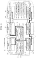
- FIG. 3 schematically shows a configuration of a network system 2 according to the present embodiment and an arrangement thereof in the vehicle 100.
- each intermediate device includes one communication unit. That is, the first intermediate device 21, the second intermediate device 22, the third intermediate device 23, the fourth intermediate device 24, the fifth intermediate device 25, and the sixth intermediate device 26 include one communication unit 213, 223, 233, 243, 253, 263, respectively. These are connected by the communication lines 11 provided in a ring.
- the upper device 10 can communicate with any intermediate device except the intermediate device having the communication unit in which the failure has occurred, via a clockwise communication path or a counterclockwise communication path.
- the first lower device 31 is connected to the third intermediate device 23 in addition to the first intermediate device 21. That is, the second communication unit 312 of the first lower device 31 is connected to the communication unit 233 of the third intermediate device 23 via the communication line 13. Further, unlike the first embodiment, the communication unit 332 of the third lower device 33 is connected to the communication unit 243 of the fourth intermediate device 24 via the communication line 15. In the present embodiment, unlike the first embodiment, if a failure occurs in any communication unit provided in the intermediate device, communication via the intermediate device cannot be performed. Therefore, measures are taken such as connecting one lower device to two intermediate devices, and connecting two lower devices having equivalent functions to different intermediate devices to ensure redundancy.
- the second communication unit 312 of the first lower device 31 may be connected, via the communication line 13, to any communication unit of an intermediate device other than the communication unit 233 of the third intermediate device 23 except the communication unit 213 of the first intermediate device 21 connected to the first communication unit 311 via the communication line 12.
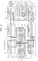
- FIG. 4 shows failure occurrence locations in the examples.
- This example is an example in which a failure has occurred in the communication unit 213 of the first intermediate device 21.
- the upper device 10 cannot communicate with the first lower device 31 via the first intermediate device 21.
- the upper device 10 can continue to control the first lower device 31 by communicating with the first lower device 31 via the third intermediate device 23.
- This example is an example in which a failure has occurred in the communication line 11 between the first intermediate device 21 and the fifth intermediate device 25 due to disconnection or the like.
- the upper device 10 cannot communicate with the first lower device 31 via the sixth intermediate device 26, the fourth intermediate device 24, the second intermediate device 22, the fifth intermediate device 25, and the first intermediate device 21.
- the upper device 10 can continue to control the first lower device 31 by communicating with the first lower device 31 via the third intermediate device 23 and the first intermediate device 21. Further, the upper device 10 can continue to control the first lower device 31 also by communicating with the first lower device 31 via the third intermediate device 23 and the communication line 13.
- This example is an example in which a failure has occurred in the first communication unit 311 of the first lower device 31.
- the first lower device 31 cannot communicate with the upper device 10 via the first communication unit 311.
- the first lower device 31 communicates with the upper device 10 via the second communication unit 312. Thereby, the upper device 10 can continue to control the first lower device 31.
- This example is an example in which a failure has occurred in the second lower device 32.
- the upper device 10 cannot cause the second lower device 32 to perform its function.
- the upper device 10 can continue control by communicating with the third lower device 33 that has the function equivalent to that of the second lower device 32 and by using the function of the third lower device 33.
- This example is an example in which a failure has occurred in the communication line 15 between the third lower device 33 and the fourth intermediate device 24 due to disconnection or the like.
- the upper device 10 cannot cause the third lower device 33 to perform its function.
- the upper device 10 can continue control by communicating with the second lower device 32 that has the function equivalent to that of the third lower device 33 and by using the function of the second lower device 32.
- This example is an example in which a failure has occurred in the first communication unit 101 of the upper device 10.
- the upper device 10 cannot communicate with the intermediate devices with the first communication unit 101 via the counterclockwise communication path.
- the upper device 10 can communicate with the intermediate devices with the second communication unit 102 via the clockwise communication path, the upper device 10 can continue to control the lower devices subordinate to the intermediate devices.
- two communication paths are provided between the upper device and the lower devices.
- two lower devices having the equivalent functions can communicate with the upper device via different communication paths.
- redundancy can be suitably provided to the network system 2, and robustness against failure that may occur in each unit can be improved.
- one communication unit is provided in each intermediate device, thereby cost can be suppressed as compared with the first embodiment in which two communication units are provided in each intermediate device.
- separately arranging a plurality of intermediate devices in various positions of the vehicle 100 can facilitate connection of the lower devices with the nearby intermediate devices regardless of the positions of the lower devices in the vehicle 100.
- two communication paths are provided by providing a ring communication path.
- other routes may be further added so that three or more communication paths are provided between the upper device 10 and each intermediate device.
- the invention is not limited to the above embodiments, and may be appropriately modified by, for example, partially implementing or combining the features of the embodiments.
- the invention is not limited to be applied to the network system, and can be applied to an in-vehicle device such as a device included in the network system, a control method executed by an in-vehicle device having a processor and a memory, a control program, a computer-readable non-transitory storage medium that stores the control program, and a vehicle equipped with the network system, etc.
- the invention can be applied to network systems other than a network system mounted on the vehicle.
- the invention is advantageous for a network system mounted on a vehicle or the like.
Landscapes
- Engineering & Computer Science (AREA)
- Computer Networks & Wireless Communication (AREA)
- Signal Processing (AREA)
- Health & Medical Sciences (AREA)
- Computing Systems (AREA)
- General Health & Medical Sciences (AREA)
- Medical Informatics (AREA)
- Small-Scale Networks (AREA)
Abstract
An in-vehicle network system (1) includes an upper device (10), a first intermediate device (21), and a first lower device (31). The first intermediate device (21) includes a first communication unit (211) and a second communication unit (212) that are arranged redundantly and that have a communication function. The first intermediate device (21) is configured to communicate with the upper device (10) via a plurality of communication paths. The first lower device (31) is connected to the first communication unit (211) and the second communication unit (212) of the first intermediate device (21).
Description
- The invention relates to an in-vehicle network system mounted on a vehicle or the like.
- A plurality of electronic devices called electronic control units (ECUs) and a plurality of electronic component devices are mounted on a vehicle. These devices execute respective functions of the vehicle.
- Japanese Unexamined Patent Application Publication No.
2014-78800 JP 2014-78800 A - In such a network system described in
JP 2014-78800 A - The invention provides a highly robust in-vehicle network system.
- A first aspect of the invention relates to an in-vehicle network system. The in-vehicle network system includes an upper device, a first intermediate device, and a first lower device. The first intermediate device includes a first communication unit and a second communication unit that are arranged redundantly and that have a communication function. The first intermediate device is configured to communicate with the upper device via a plurality of communication paths. The first lower device is connected to the first communication unit and the second communication unit of the first intermediate device.
- In the in-vehicle network system according to the first aspect, the first intermediate device may be configured to function as a gateway that relays communication between the upper device and the first lower device. The upper device may be configured to create control data for controlling an actuator mounted on a vehicle and transmit the control data to the first lower device via the first intermediate device. The first lower device may be configured to control the actuator based on the control data.
- In the in-vehicle network system according to the first aspect, the in-vehicle network system may include a plurality of intermediate devices including the first intermediate device. The upper device and the intermediate devices may be connected to each other by a communication line provided in a ring.
- In the in-vehicle network system according to the first aspect, the first lower device may include a first lower communication unit connected to the first communication unit of the first intermediate device, and a second lower communication unit connected to the second communication unit of the first intermediate device.
- A second aspect of the invention relates to an in-vehicle network system. The in-vehicle network system includes an upper device, a second intermediate device, a second lower device, and a third lower device. The second intermediate device includes a first communication unit and a second communication unit that are arranged redundantly and that have a communication function. The second intermediate device is configured to communicate with the upper device via a plurality of communication paths. The second lower device is connected to the first communication unit of the second intermediate device. The third lower device is connected to the second communication unit of the second intermediate device and has a function equivalent to a function of the second lower device.
- A third aspect of the invention relates to an in-vehicle network system. The in-vehicle network system includes an upper device, a first intermediate device, a third intermediate device, and a first lower device. The first intermediate device includes a first communication unit having a communication function and is configured to communicate with the upper device via a plurality of communication paths. The third intermediate device includes a third communication unit having a communication function and is configured to communicate with the upper device via a plurality of communication paths. The first lower device is connected to the first communication unit and the third communication unit.
- A fourth aspect of the invention relates to an in-vehicle network system. The in-vehicle network system includes an upper device, a second intermediate device, a fourth intermediate device, a second lower device, and a third lower device. The second intermediate device includes a second communication unit having a communication function and is configured to communicate with the upper device via a plurality of communication paths. The fourth intermediate device includes a fourth communication unit having a communication function and is configured to communicate with the upper device via a plurality of communication paths. The second lower device is connected to the second communication unit. The third lower device is connected to the fourth communication unit and has a function equivalent to a function of the second lower device.
- According to the invention, a highly robust in-vehicle network system can be provided since the configurations of the communication systems, the communication paths, and the devices are made redundant.
- Features, advantages, and technical and industrial significance of exemplary embodiments of the invention will be described below with reference to the accompanying drawings, in which like signs denote like elements, and wherein:
-
FIG. 1 is a diagram showing a configuration of a network system according to a first embodiment of the invention; -
FIG. 2 is a diagram showing an example of failure occurrence locations of the network system according to the first embodiment of the invention; -
FIG. 3 is a diagram showing a configuration of a network system according to a second embodiment of the invention; and -
FIG. 4 is a diagram showing an example of failure occurrence locations of the network system according to the second embodiment of the invention. - In the embodiments of the invention, a plurality of communication paths are provided between upper and lower devices of a network system. Alternatively, the network system includes two lower devices having equivalent functions, and the two lower devices communicate with the upper device via different communication paths. As a result, redundancy can be suitably provided to the network system, and robustness against failure that may occur in each unit can be improved.
- Hereinafter, a first embodiment of the invention will be described in detail with reference to the drawings.
-
FIG. 1 schematically shows a configuration of anetwork system 1 according to the present embodiment and an arrangement thereof in avehicle 100. - In the present embodiment, the
network system 1 includes an upper node, intermediate nodes, and lower nodes. The upper node is, for example, a relatively highly functional ECU that collectively executes calculations for various vehicle control functions. The lower node is, for example, a sensor, an actuator, or an ECU having a relatively specialized function for individually controlling the sensor or the actuator. The intermediate node is, for example, an ECU that functions as a gateway to relay communication between the upper node and the lower node. - The
network system 1 includes anupper device 10 as the upper node. One or more intermediate devices, which serve as the intermediate nodes, are connected subordinate to theupper device 10 by, for example, a ring-type connection topology. That is, in the example shown inFIG. 1 , a firstintermediate device 21, a secondintermediate device 22, a thirdintermediate device 23, a fourthintermediate device 24, a fifthintermediate device 25, and a sixthintermediate device 26 are respectively provided in a ring-type communication path with its both ends connected to theupper device 10, and are connected to theupper device 10 via another device or directly without intervention of another device. - Each intermediate device is connected to one or more lower devices which serve as the lower nodes. As an example of the lower devices,
FIG. 1 shows a firstlower device 31, a secondlower device 32, and a thirdlower device 33, and the other lower devices are not shown. The firstlower device 31 is connected to the firstintermediate device 21. The secondlower device 32 is connected to the secondintermediate device 22. The thirdlower device 33 is connected to the secondintermediate device 22. - In this example, the
upper device 10 collects, via each intermediate device serving as a gateway, information on thevehicle 100 or information surrounding thevehicle 100 from the lower devices that control sensors. This information may include, for example, operation conditions of actuators, etc., driving conditions of thevehicle 100 such as a speed and an acceleration of thevehicle 100, environmental conditions such as roads, objects, etc. surrounding thevehicle 100, seating statuses of occupants, and details of operations performed on various components of thevehicle 100. Note that some switches, sensors, and the like such as a start switch may be directly connected to theupper device 10. In this case, theupper device 10 may acquire information from these switches, sensors, and the like without intervention of the intermediate devices. Theupper device 10 performs calculations based on the information to generate control data. The control data is data for controlling various functions of thevehicle 100, such as an autonomous driving function, a self-parking function, drive assistance functions including collision avoidance, lane keeping, follow-up of the preceding vehicle, and maintaining speed, operational control of an engine, a transmission, a cooling device, and an air conditioner, charging and discharging control for a battery, lighting of headlamps in accordance with illuminance, permission of unlocking doors based on authentication using a mobile device (electronic key), and presentation of information to a user. Theupper device 10 transmits the control data to the intermediate devices, and causes the intermediate devices to perform operation corresponding to the control data. Theupper device 10 transmits, via the intermediate devices serving as gateways, the control data to the lower devices that control the actuators, and causes the lower devices to perform operation corresponding to the control data. In such anetwork system 1, total cost is reduced by integrating various control functions of thevehicle 100 into the highly functionalupper device 10 and relatively simplifying the configurations of the intermediate devices and the lower devices instead. - Each of the above devices is typically configured to include a control unit, such as a processor or a microcomputer, and a memory. However, there may be lower devices that include sensors or actuators but do not include a control unit or a memory.
- The
upper device 10 is arranged, for example, in or near a center console of thevehicle 100. The intermediate devices are arranged separately in various positions of thevehicle 100. The lower devices are arranged at suitable positions according to their functions, and are typically directly connected to the nearest intermediate devices without intervention of other devices. - The
upper device 10 includes afirst communication unit 101 and asecond communication unit 102. - The first
intermediate device 21, the secondintermediate device 22, the thirdintermediate device 23, the fourthintermediate device 24, the fifthintermediate device 25, and the sixthintermediate device 26 include afirst communication unit second communication unit - A first
lower device 31 includes afirst communication unit 311 and asecond communication unit 312. The firstlower device 31 is, for example, an electric power steering (EPS) system. The firstlower device 31 is a device in which, in addition to a communication function, a power supply system and an actuator system are also duplexed and has a redundant configuration itself. For example, even if a failure occurs in one of thefirst communication unit 311 and thesecond communication unit 312, any one system in the firstlower device 31 can be controlled through communication with the other communication unit. - The second
lower device 32 includes acommunication unit 321. - The third
lower device 33 includes acommunication unit 332. - The second
lower device 32 and the thirdlower device 33 have functions equivalent to each other. These are, for example, sensors of a radio detection and ranging (radar) system and a laser-imaging detection and ranging (lidar) system used for a safety improvement function such as collision avoidance of thevehicle 100. As described above, the secondlower device 32 and the thirdlower device 33 have functions equivalent to each other, which are detecting an object around thevehicle 100 and measuring the distance between the object and thevehicle 100. Here, the equivalent functions include not only completely identical functions but also similar and alternative functions. Unlike the firstlower device 31, the secondlower device 32 and the thirdlower device 33 do not have redundant configurations themselves, but achieve a redundant configuration as a whole as a safety improvement function with two devices having functions equivalent to each other. For example, if no failure occurs in a first communication system and a second communication system, theupper device 10 communicates with the first communication system of the secondlower device 32 and the second communication system of the thirdlower device 33 via each intermediate device, thereby using both functions of the secondlower device 32 and the thirdlower device 33 in a mutually complementary manner. If a failure occurs in one of the secondlower device 32 and the thirdlower device 33, theupper device 10 communicates only with the other device and uses the function of the other device. In this way, the safety improvement function can be continuously executed. The secondlower device 32 and the thirdlower device 33 may be two identical devices. - The
upper device 10 and the intermediate devices are connected bycommunication lines 11 provided in a ring. Each communication unit described above is, for example, a communication integrated circuit (IC) when the communication standard is the Controller Area Network (CAN) (registered trademark) standard, and is, for example, an Ethernet switch when the communication standard is the Ethernet (registered trademark) standard. - Each of the
upper device 10 and the intermediate devices has two communication units arranged redundantly, and the communication unit of each device is connected to the communication unit of one of the two adjacent devices. In the example shown inFIG. 1 , thefirst communication unit 101 of theupper device 10 is connected to thesecond communication unit 232 of the thirdintermediate device 23. Thefirst communication unit 231 of the thirdintermediate device 23 is connected to thesecond communication unit 212 of the firstintermediate device 21. Thefirst communication unit 211 of the firstintermediate device 21 is connected to thesecond communication unit 252 of the fifthintermediate device 25. Thefirst communication unit 251 of the fifthintermediate device 25 is connected to thesecond communication unit 222 of the secondintermediate device 22. Thefirst communication unit 221 of the secondintermediate device 22 is connected to thesecond communication unit 242 of the fourthintermediate device 24. Thefirst communication unit 241 of the fourthintermediate device 24 is connected to thesecond communication unit 262 of the sixthintermediate device 26. Thefirst communication unit 261 of the sixthintermediate device 26 is connected to thesecond communication unit 102 of theupper device 10. With the devices connected in the above manner, even if a failure occurs in any of the communication units, theupper device 10 can communicate with any intermediate device including the intermediate device having the communication unit in which the failure has occurred, via a clockwise communication path or a counterclockwise communication path. In the example shown inFIG. 1 , thefirst communication unit 101 and thesecond communication unit 102 of theupper device 10 perform communication in the counterclockwise communication path and communication in the clockwise communication path, respectively, based on their routing information. - The
first communication unit 311 of the firstlower device 31 and thefirst communication unit 211 of the firstintermediate device 21 are connected to each other via acommunication line 12, and thesecond communication unit 312 of the firstlower device 31 and thesecond communication unit 212 of the firstintermediate device 21 are connected to each other via acommunication line 13. Further, thecommunication unit 321 of the secondlower device 32 and thefirst communication unit 221 of the secondintermediate device 22 are connected to each other via acommunication line 14, and thecommunication unit 332 of the thirdlower device 33 and thesecond communication unit 222 of the secondintermediate device 22 are connected to each other via acommunication line 15. - Hereinafter, examples of processing when a failure has occurred in the
network system 1 according to the present embodiment will be described.FIG. 2 shows failure occurrence locations in the examples. - This example is an example in which a failure has occurred in the
first communication unit 211 of the firstintermediate device 21. In this case, theupper device 10 cannot communicate with the firstlower device 31 via thefirst communication unit 211. However, theupper device 10 can continue to control the firstlower device 31 by communicating with thesecond communication unit 212. - This example is an example in which a failure has occurred in the
communication line 11 between the firstintermediate device 21 and the fifthintermediate device 25 due to disconnection or the like. In this case, theupper device 10 cannot communicate with the firstlower device 31 via the sixthintermediate device 26, the fourthintermediate device 24, the secondintermediate device 22, the fifthintermediate device 25, and the firstintermediate device 21. However, theupper device 10 can continue to control the firstlower device 31 by communicating with the firstlower device 31 via the thirdintermediate device 23 and the firstintermediate device 21. - This example is an example in which a failure has occurred in the
first communication unit 311 of the firstlower device 31. In this case, theupper device 10 cannot communicate with the firstlower device 31 via thefirst communication unit 311. However, theupper device 10 can continue to control the firstlower device 31 by communicating with thesecond communication unit 312. - This example is an example in which a failure has occurred in the second
lower device 32. In this case, theupper device 10 cannot cause the secondlower device 32 to perform its function. However, theupper device 10 can continue control by communicating with the thirdlower device 33 that has the function equivalent to that of the secondlower device 32 and by using the function of the thirdlower device 33. - This example is an example in which a failure has occurred in the
communication line 15 between the thirdlower device 33 and the secondintermediate device 22 due to disconnection or the like. In this case, theupper device 10 cannot cause the thirdlower device 33 to perform its function. However, theupper device 10 can continue control by communicating with the secondlower device 32 that has the function equivalent to that of the thirdlower device 33 and by using the function of the secondlower device 32. - This example is an example in which a failure has occurred in the
first communication unit 101 of theupper device 10. In this case, theupper device 10 cannot communicate with the intermediate devices with thefirst communication unit 101 via the counterclockwise communication path. However, since theupper device 10 can communicate with the intermediate devices with thesecond communication unit 102 via the clockwise communication path, theupper device 10 can continue to control the lower devices subordinate to the intermediate devices. - In the present embodiment, two communication paths are provided between the upper device and the lower devices. Alternatively, two lower devices having equivalent functions communicate with the upper device via different communication paths. In this way, redundancy can be suitably provided to the
network system 1, and robustness against failure that may occur in each unit can be improved. - As shown in
FIG. 1 , separately arranging a plurality of intermediate devices in various positions of thevehicle 100 can facilitate connection of the lower devices with the nearby intermediate devices regardless of the positions of the lower devices in thevehicle 100. Two communication paths are provided in the present embodiment, but another communication path may be added to further increase redundancy. - Hereinafter, a second embodiment of the invention will be described with reference to the drawings. Description of items similar to those in the first embodiment will be omitted as appropriate.
-
FIG. 3 schematically shows a configuration of anetwork system 2 according to the present embodiment and an arrangement thereof in thevehicle 100. - In the present embodiment, unlike the first embodiment, each intermediate device includes one communication unit. That is, the first
intermediate device 21, the secondintermediate device 22, the thirdintermediate device 23, the fourthintermediate device 24, the fifthintermediate device 25, and the sixthintermediate device 26 include onecommunication unit communication lines 11 provided in a ring. In the present embodiment, even if a failure occurs in any of the communication units, theupper device 10 can communicate with any intermediate device except the intermediate device having the communication unit in which the failure has occurred, via a clockwise communication path or a counterclockwise communication path. - Unlike the first embodiment, the first
lower device 31 is connected to the thirdintermediate device 23 in addition to the firstintermediate device 21. That is, thesecond communication unit 312 of the firstlower device 31 is connected to thecommunication unit 233 of the thirdintermediate device 23 via thecommunication line 13. Further, unlike the first embodiment, thecommunication unit 332 of the thirdlower device 33 is connected to thecommunication unit 243 of the fourthintermediate device 24 via thecommunication line 15. In the present embodiment, unlike the first embodiment, if a failure occurs in any communication unit provided in the intermediate device, communication via the intermediate device cannot be performed. Therefore, measures are taken such as connecting one lower device to two intermediate devices, and connecting two lower devices having equivalent functions to different intermediate devices to ensure redundancy. Thesecond communication unit 312 of the firstlower device 31 may be connected, via thecommunication line 13, to any communication unit of an intermediate device other than thecommunication unit 233 of the thirdintermediate device 23 except thecommunication unit 213 of the firstintermediate device 21 connected to thefirst communication unit 311 via thecommunication line 12. - Hereinafter, examples of processing when a failure occurs in the
network system 1 according to the present embodiment will be described.FIG. 4 shows failure occurrence locations in the examples. - This example is an example in which a failure has occurred in the
communication unit 213 of the firstintermediate device 21. In this case, theupper device 10 cannot communicate with the firstlower device 31 via the firstintermediate device 21. However, theupper device 10 can continue to control the firstlower device 31 by communicating with the firstlower device 31 via the thirdintermediate device 23. - This example is an example in which a failure has occurred in the
communication line 11 between the firstintermediate device 21 and the fifthintermediate device 25 due to disconnection or the like. In this case, theupper device 10 cannot communicate with the firstlower device 31 via the sixthintermediate device 26, the fourthintermediate device 24, the secondintermediate device 22, the fifthintermediate device 25, and the firstintermediate device 21. However, theupper device 10 can continue to control the firstlower device 31 by communicating with the firstlower device 31 via the thirdintermediate device 23 and the firstintermediate device 21. Further, theupper device 10 can continue to control the firstlower device 31 also by communicating with the firstlower device 31 via the thirdintermediate device 23 and thecommunication line 13. - This example is an example in which a failure has occurred in the
first communication unit 311 of the firstlower device 31. In this case, the firstlower device 31 cannot communicate with theupper device 10 via thefirst communication unit 311. However, the firstlower device 31 communicates with theupper device 10 via thesecond communication unit 312. Thereby, theupper device 10 can continue to control the firstlower device 31. - This example is an example in which a failure has occurred in the second
lower device 32. In this case, theupper device 10 cannot cause the secondlower device 32 to perform its function. However, theupper device 10 can continue control by communicating with the thirdlower device 33 that has the function equivalent to that of the secondlower device 32 and by using the function of the thirdlower device 33. - This example is an example in which a failure has occurred in the
communication line 15 between the thirdlower device 33 and the fourthintermediate device 24 due to disconnection or the like. In this case, theupper device 10 cannot cause the thirdlower device 33 to perform its function. However, theupper device 10 can continue control by communicating with the secondlower device 32 that has the function equivalent to that of the thirdlower device 33 and by using the function of the secondlower device 32. - This example is an example in which a failure has occurred in the
first communication unit 101 of theupper device 10. In this case, theupper device 10 cannot communicate with the intermediate devices with thefirst communication unit 101 via the counterclockwise communication path. However, since theupper device 10 can communicate with the intermediate devices with thesecond communication unit 102 via the clockwise communication path, theupper device 10 can continue to control the lower devices subordinate to the intermediate devices. - In the present embodiment, as in the first embodiment, two communication paths are provided between the upper device and the lower devices. Alternatively, two lower devices having the equivalent functions can communicate with the upper device via different communication paths. In this way, redundancy can be suitably provided to the
network system 2, and robustness against failure that may occur in each unit can be improved. In particular, in the present embodiment, one communication unit is provided in each intermediate device, thereby cost can be suppressed as compared with the first embodiment in which two communication units are provided in each intermediate device. - As shown in
FIG. 3 , as in the first embodiment, separately arranging a plurality of intermediate devices in various positions of thevehicle 100 can facilitate connection of the lower devices with the nearby intermediate devices regardless of the positions of the lower devices in thevehicle 100. In the above embodiments, two communication paths are provided by providing a ring communication path. Alternatively, other routes may be further added so that three or more communication paths are provided between theupper device 10 and each intermediate device. - The invention is not limited to the above embodiments, and may be appropriately modified by, for example, partially implementing or combining the features of the embodiments.
- The invention is not limited to be applied to the network system, and can be applied to an in-vehicle device such as a device included in the network system, a control method executed by an in-vehicle device having a processor and a memory, a control program, a computer-readable non-transitory storage medium that stores the control program, and a vehicle equipped with the network system, etc. The invention can be applied to network systems other than a network system mounted on the vehicle.
- The invention is advantageous for a network system mounted on a vehicle or the like.
Claims (7)
- An in-vehicle network system (1) comprising:an upper device (10);a first intermediate device (21) including a first communication unit (211) and a second communication unit (212) that are arranged redundantly and that have a communication function, the first intermediate device (21) being configured to communicate with the upper device (10) via a plurality of communication paths; anda first lower device (31) connected to the first communication unit (211) and the second communication unit (212) of the first intermediate device (21).
- The in-vehicle network system (1) according to claim 1, wherein:the first intermediate device (21) is configured to function as a gateway that relays communication between the upper device (10) and the first lower device (31);the upper device (10) is configured to create control data for controlling an actuator mounted on a vehicle and transmit the control data to the first lower device (31) via the first intermediate device (21); andthe first lower device (31) is configured to control the actuator based on the control data.
- The in-vehicle network system (1) according to claim 1, wherein:the in-vehicle network system includes a plurality of intermediate devices (21, 22, 23, 24, 25) including the first intermediate device (21); andthe upper device (10) and the intermediate devices (21, 22, 23, 24, 25) are connected to each other by a communication line (11) provided in a ring.
- The in-vehicle network system (1) according to claim 1, wherein the first lower device (31) includes a first lower communication unit (311) connected to the first communication unit (211) of the first intermediate device (21), and a second lower communication unit (312) connected to the second communication unit (212) of the first intermediate device (21).
- An in-vehicle network system (1) comprising:an upper device (10);a second intermediate device (22) including a first communication unit (221) and a second communication unit (222) that are arranged redundantly and that have a communication function, the second intermediate device (22) being configured to communicate with the upper device (10) via a plurality of communication paths;a second lower device (32) connected to the first communication unit (221) of the second intermediate device (22); anda third lower device (33) connected to the second communication unit (222) of the second intermediate device (22) and having a function equivalent to a function of the second lower device (32).
- An in-vehicle network system (2), comprising:an upper device (10);a first intermediate device (21) that includes a first communication unit (213) having a communication function and that is configured to communicate with the upper device (10) via a plurality of communication paths;a third intermediate device (23) that includes a third communication unit (233) having a communication function and that is configured to communicate with the upper device (10) via a plurality of communication paths; anda first lower device (31) connected to the first communication unit (213) and the third communication unit (233).
- An in-vehicle network system (2) comprising:an upper device (10);a second intermediate device (22) that includes a second communication unit (223) having a communication function and that is configured to communicate with the upper device (10) via a plurality of communication paths;a fourth intermediate device (24) that includes a fourth communication unit (243) having a communication function and that is configured to communicate with the upper device (10) via a plurality of communication paths;a second lower device (32) connected to the second communication unit (223); anda third lower device (33) connected to the fourth communication unit (243) and having a function equivalent to a function of the second lower device (32).
Applications Claiming Priority (1)
| Application Number | Priority Date | Filing Date | Title |
|---|---|---|---|
| JP2019157922A JP7252097B2 (en) | 2019-08-30 | 2019-08-30 | In-vehicle network system |
Publications (1)
| Publication Number | Publication Date |
|---|---|
| EP3787236A1 true EP3787236A1 (en) | 2021-03-03 |
Family
ID=72243004
Family Applications (1)
| Application Number | Title | Priority Date | Filing Date |
|---|---|---|---|
| EP20192850.4A Pending EP3787236A1 (en) | 2019-08-30 | 2020-08-26 | In-vehicle network system |
Country Status (4)
| Country | Link |
|---|---|
| US (1) | US11622250B2 (en) |
| EP (1) | EP3787236A1 (en) |
| JP (1) | JP7252097B2 (en) |
| CN (1) | CN112449321B (en) |
Families Citing this family (3)
| Publication number | Priority date | Publication date | Assignee | Title |
|---|---|---|---|---|
| DE102020211932A1 (en) * | 2020-09-23 | 2022-03-24 | Robert Bosch Gesellschaft mit beschränkter Haftung | Communication system for a vehicle and operating method therefor |
| JP7528826B2 (en) * | 2021-03-12 | 2024-08-06 | マツダ株式会社 | In-vehicle communication device and communication management method |
| US12603797B2 (en) * | 2024-06-14 | 2026-04-14 | Caterpillar Inc. | Method for operating a ring communication network |
Citations (5)
| Publication number | Priority date | Publication date | Assignee | Title |
|---|---|---|---|---|
| JP2014078800A (en) | 2012-10-09 | 2014-05-01 | Denso Corp | Repeater |
| US20140341224A1 (en) * | 2011-09-19 | 2014-11-20 | Michael Armbruster | Systems and Methods for Operating a Network Arrangement |
| US20140376561A1 (en) * | 2011-09-19 | 2014-12-25 | Michael Armbruster | Method for Operating a Communication Network, and Network Arrangement |
| WO2018050648A1 (en) * | 2016-09-13 | 2018-03-22 | HELLA GmbH & Co. KGaA | Device for energy and/or data transmission |
| JP2019104338A (en) * | 2017-12-12 | 2019-06-27 | 矢崎総業株式会社 | Onboard system and detector hub |
Family Cites Families (12)
| Publication number | Priority date | Publication date | Assignee | Title |
|---|---|---|---|---|
| JP4320734B2 (en) * | 2004-09-07 | 2009-08-26 | 横河電機株式会社 | Mobile communication system |
| DE102012210057A1 (en) * | 2012-06-14 | 2013-12-19 | Continental Automotive Gmbh | Annular network for a vehicle |
| DE102012215765A1 (en) * | 2012-09-05 | 2014-05-15 | Robert Bosch Gmbh | Gateway module for a communication system, communication system and method for transferring data between users of a communication system |
| CN105235671B (en) * | 2015-10-13 | 2018-06-22 | 南车株洲电力机车有限公司 | The pressure control redundant apparatus and control method of a kind of checking cylinder |
| US10070286B2 (en) * | 2016-05-27 | 2018-09-04 | Analog Devices, Inc. | Single-wire sensor bus |
| CN108205305B (en) * | 2016-12-20 | 2020-05-19 | 比亚迪股份有限公司 | CAN-based train network control system and method |
| JP6898807B2 (en) | 2017-08-23 | 2021-07-07 | 日立Astemo株式会社 | Vehicle control device |
| JP6878324B2 (en) | 2018-01-31 | 2021-05-26 | 日立Astemo株式会社 | In-vehicle network system, electronic control device |
| EP4094996A1 (en) * | 2018-06-29 | 2022-11-30 | Aptiv Technologies Limited | A method comprising distributing through a power interface of a power and data center power and data for automotive applications |
| JP7043446B2 (en) * | 2019-03-18 | 2022-03-29 | 矢崎総業株式会社 | Vehicular communication system |
| CN114900463A (en) * | 2019-05-13 | 2022-08-12 | 华为技术有限公司 | In-vehicle communication system, in-vehicle communication method and device |
| CA3057937A1 (en) * | 2019-10-08 | 2021-04-08 | Neutron Automotive Controls Inc. | Redundant ethernet network and sensor processing system for vehicles and related methods |
-
2019
- 2019-08-30 JP JP2019157922A patent/JP7252097B2/en active Active
-
2020
- 2020-08-20 US US16/998,054 patent/US11622250B2/en active Active
- 2020-08-26 EP EP20192850.4A patent/EP3787236A1/en active Pending
- 2020-08-27 CN CN202010879857.0A patent/CN112449321B/en active Active
Patent Citations (6)
| Publication number | Priority date | Publication date | Assignee | Title |
|---|---|---|---|---|
| US20140341224A1 (en) * | 2011-09-19 | 2014-11-20 | Michael Armbruster | Systems and Methods for Operating a Network Arrangement |
| US20140376561A1 (en) * | 2011-09-19 | 2014-12-25 | Michael Armbruster | Method for Operating a Communication Network, and Network Arrangement |
| JP2014078800A (en) | 2012-10-09 | 2014-05-01 | Denso Corp | Repeater |
| WO2018050648A1 (en) * | 2016-09-13 | 2018-03-22 | HELLA GmbH & Co. KGaA | Device for energy and/or data transmission |
| US20190273632A1 (en) * | 2016-09-13 | 2019-09-05 | HELLA GmbH & Co. KGaA | Device for Energy and/or Data Transmission |
| JP2019104338A (en) * | 2017-12-12 | 2019-06-27 | 矢崎総業株式会社 | Onboard system and detector hub |
Also Published As
| Publication number | Publication date |
|---|---|
| JP7252097B2 (en) | 2023-04-04 |
| US20210067929A1 (en) | 2021-03-04 |
| JP2021036643A (en) | 2021-03-04 |
| US11622250B2 (en) | 2023-04-04 |
| CN112449321A (en) | 2021-03-05 |
| CN112449321B (en) | 2024-12-03 |
Similar Documents
| Publication | Publication Date | Title |
|---|---|---|
| US11622250B2 (en) | In-vehicle network system | |
| US10780783B2 (en) | Onboard vehicle communication system | |
| EP3764590B1 (en) | An in-vehicle system for suppressing the standby power of electronic control units | |
| CN110035939B (en) | Vehicle control device | |
| CN110615004A (en) | Method and device for controlling safety-relevant processes, and vehicle | |
| US20060116803A1 (en) | Redundant control unit arrangement | |
| CN111935201A (en) | In-vehicle communication system, in-vehicle communication method and device | |
| US11249543B2 (en) | In-vehicle control device | |
| EP3790233B1 (en) | In-vehicle network system | |
| EP3220268B1 (en) | Fault-tolerant high-performance computer system for autonomous vehicle maneuvering | |
| JP2017024456A (en) | Backup battery system | |
| CN102854871A (en) | Bus control system and engineering machinery | |
| EP3764601B1 (en) | In-vehicle network system | |
| US20170208471A1 (en) | Motor vehicle having a communications device | |
| US10756566B2 (en) | Method and apparatus for supplying electric power to a device | |
| JP6417984B2 (en) | In-vehicle communication system | |
| JP6627598B2 (en) | In-vehicle power supply | |
| CN109691018B (en) | System for energy and/or data transmission | |
| JP6558286B2 (en) | In-vehicle power supply | |
| CN112440908B (en) | Network Systems | |
| US10277419B2 (en) | Hybrid network end system device | |
| KR20160114851A (en) | Vehicle network control system and vehicel network control method | |
| JP2008260411A (en) | Gateway device and its control method |
Legal Events
| Date | Code | Title | Description |
|---|---|---|---|
| PUAI | Public reference made under article 153(3) epc to a published international application that has entered the european phase |
Free format text: ORIGINAL CODE: 0009012 |
|
| STAA | Information on the status of an ep patent application or granted ep patent |
Free format text: STATUS: REQUEST FOR EXAMINATION WAS MADE |
|
| 17P | Request for examination filed |
Effective date: 20200826 |
|
| AK | Designated contracting states |
Kind code of ref document: A1 Designated state(s): AL AT BE BG CH CY CZ DE DK EE ES FI FR GB GR HR HU IE IS IT LI LT LU LV MC MK MT NL NO PL PT RO RS SE SI SK SM TR |
|
| AX | Request for extension of the european patent |
Extension state: BA ME |
|
| STAA | Information on the status of an ep patent application or granted ep patent |
Free format text: STATUS: EXAMINATION IS IN PROGRESS |
|
| 17Q | First examination report despatched |
Effective date: 20221129 |