EP3787124A1 - Sealed electrical terminal with adhesive flow-out retarder - Google Patents
Sealed electrical terminal with adhesive flow-out retarder Download PDFInfo
- Publication number
- EP3787124A1 EP3787124A1 EP20192631.8A EP20192631A EP3787124A1 EP 3787124 A1 EP3787124 A1 EP 3787124A1 EP 20192631 A EP20192631 A EP 20192631A EP 3787124 A1 EP3787124 A1 EP 3787124A1
- Authority
- EP
- European Patent Office
- Prior art keywords
- terminal
- attachment portion
- wire attachment
- flow barrier
- adhesive
- Prior art date
- Legal status (The legal status is an assumption and is not a legal conclusion. Google has not performed a legal analysis and makes no representation as to the accuracy of the status listed.)
- Granted
Links
Images


Classifications
-
- H—ELECTRICITY
- H01—ELECTRIC ELEMENTS
- H01R—ELECTRICALLY-CONDUCTIVE CONNECTIONS; STRUCTURAL ASSOCIATIONS OF A PLURALITY OF MUTUALLY-INSULATED ELECTRICAL CONNECTING ELEMENTS; COUPLING DEVICES; CURRENT COLLECTORS
- H01R13/00—Details of coupling devices of the kinds covered by groups H01R12/70 or H01R24/00 - H01R33/00
- H01R13/46—Bases; Cases
- H01R13/52—Dustproof, splashproof, drip-proof, waterproof, or flameproof cases
- H01R13/5219—Sealing means between coupling parts, e.g. interfacial seal
- H01R13/5221—Sealing means between coupling parts, e.g. interfacial seal having cable sealing means
-
- H—ELECTRICITY
- H01—ELECTRIC ELEMENTS
- H01R—ELECTRICALLY-CONDUCTIVE CONNECTIONS; STRUCTURAL ASSOCIATIONS OF A PLURALITY OF MUTUALLY-INSULATED ELECTRICAL CONNECTING ELEMENTS; COUPLING DEVICES; CURRENT COLLECTORS
- H01R4/00—Electrically-conductive connections between two or more conductive members in direct contact, i.e. touching one another; Means for effecting or maintaining such contact; Electrically-conductive connections having two or more spaced connecting locations for conductors and using contact members penetrating insulation
- H01R4/70—Insulation of connections
- H01R4/72—Insulation of connections using a heat shrinking insulating sleeve
-
- H—ELECTRICITY
- H01—ELECTRIC ELEMENTS
- H01R—ELECTRICALLY-CONDUCTIVE CONNECTIONS; STRUCTURAL ASSOCIATIONS OF A PLURALITY OF MUTUALLY-INSULATED ELECTRICAL CONNECTING ELEMENTS; COUPLING DEVICES; CURRENT COLLECTORS
- H01R11/00—Individual connecting elements providing two or more spaced connecting locations for conductive members which are, or may be, thereby interconnected, e.g. end pieces for wires or cables supported by the wire or cable and having means for facilitating electrical connection to some other wire, terminal, or conductive member, blocks of binding posts
- H01R11/11—End pieces or tapping pieces for wires, supported by the wire and for facilitating electrical connection to some other wire, terminal or conductive member
- H01R11/12—End pieces terminating in an eye, hook, or fork
-
- H—ELECTRICITY
- H01—ELECTRIC ELEMENTS
- H01R—ELECTRICALLY-CONDUCTIVE CONNECTIONS; STRUCTURAL ASSOCIATIONS OF A PLURALITY OF MUTUALLY-INSULATED ELECTRICAL CONNECTING ELEMENTS; COUPLING DEVICES; CURRENT COLLECTORS
- H01R4/00—Electrically-conductive connections between two or more conductive members in direct contact, i.e. touching one another; Means for effecting or maintaining such contact; Electrically-conductive connections having two or more spaced connecting locations for conductors and using contact members penetrating insulation
- H01R4/10—Electrically-conductive connections between two or more conductive members in direct contact, i.e. touching one another; Means for effecting or maintaining such contact; Electrically-conductive connections having two or more spaced connecting locations for conductors and using contact members penetrating insulation effected solely by twisting, wrapping, bending, crimping, or other permanent deformation
- H01R4/18—Electrically-conductive connections between two or more conductive members in direct contact, i.e. touching one another; Means for effecting or maintaining such contact; Electrically-conductive connections having two or more spaced connecting locations for conductors and using contact members penetrating insulation effected solely by twisting, wrapping, bending, crimping, or other permanent deformation by crimping
- H01R4/20—Electrically-conductive connections between two or more conductive members in direct contact, i.e. touching one another; Means for effecting or maintaining such contact; Electrically-conductive connections having two or more spaced connecting locations for conductors and using contact members penetrating insulation effected solely by twisting, wrapping, bending, crimping, or other permanent deformation by crimping using a crimping sleeve
-
- H—ELECTRICITY
- H01—ELECTRIC ELEMENTS
- H01R—ELECTRICALLY-CONDUCTIVE CONNECTIONS; STRUCTURAL ASSOCIATIONS OF A PLURALITY OF MUTUALLY-INSULATED ELECTRICAL CONNECTING ELEMENTS; COUPLING DEVICES; CURRENT COLLECTORS
- H01R4/00—Electrically-conductive connections between two or more conductive members in direct contact, i.e. touching one another; Means for effecting or maintaining such contact; Electrically-conductive connections having two or more spaced connecting locations for conductors and using contact members penetrating insulation
- H01R4/58—Electrically-conductive connections between two or more conductive members in direct contact, i.e. touching one another; Means for effecting or maintaining such contact; Electrically-conductive connections having two or more spaced connecting locations for conductors and using contact members penetrating insulation characterised by the form or material of the contacting members
-
- H—ELECTRICITY
- H01—ELECTRIC ELEMENTS
- H01R—ELECTRICALLY-CONDUCTIVE CONNECTIONS; STRUCTURAL ASSOCIATIONS OF A PLURALITY OF MUTUALLY-INSULATED ELECTRICAL CONNECTING ELEMENTS; COUPLING DEVICES; CURRENT COLLECTORS
- H01R43/00—Apparatus or processes specially adapted for manufacturing, assembling, maintaining, or repairing of line connectors or current collectors or for joining electric conductors
- H01R43/18—Apparatus or processes specially adapted for manufacturing, assembling, maintaining, or repairing of line connectors or current collectors or for joining electric conductors for manufacturing bases or cases for contact members
-
- H—ELECTRICITY
- H02—GENERATION; CONVERSION OR DISTRIBUTION OF ELECTRIC POWER
- H02G—INSTALLATION OF ELECTRIC CABLES OR LINES, OR OF COMBINED OPTICAL AND ELECTRIC CABLES OR LINES
- H02G15/00—Cable fittings
- H02G15/08—Cable junctions
- H02G15/18—Cable junctions protected by sleeves, e.g. for communication cable
- H02G15/1806—Heat shrinkable sleeves
-
- H—ELECTRICITY
- H01—ELECTRIC ELEMENTS
- H01R—ELECTRICALLY-CONDUCTIVE CONNECTIONS; STRUCTURAL ASSOCIATIONS OF A PLURALITY OF MUTUALLY-INSULATED ELECTRICAL CONNECTING ELEMENTS; COUPLING DEVICES; CURRENT COLLECTORS
- H01R2201/00—Connectors or connections adapted for particular applications
- H01R2201/26—Connectors or connections adapted for particular applications for vehicles
-
- H—ELECTRICITY
- H01—ELECTRIC ELEMENTS
- H01R—ELECTRICALLY-CONDUCTIVE CONNECTIONS; STRUCTURAL ASSOCIATIONS OF A PLURALITY OF MUTUALLY-INSULATED ELECTRICAL CONNECTING ELEMENTS; COUPLING DEVICES; CURRENT COLLECTORS
- H01R4/00—Electrically-conductive connections between two or more conductive members in direct contact, i.e. touching one another; Means for effecting or maintaining such contact; Electrically-conductive connections having two or more spaced connecting locations for conductors and using contact members penetrating insulation
- H01R4/02—Soldered or welded connections
- H01R4/029—Welded connections
-
- H—ELECTRICITY
- H02—GENERATION; CONVERSION OR DISTRIBUTION OF ELECTRIC POWER
- H02G—INSTALLATION OF ELECTRIC CABLES OR LINES, OR OF COMBINED OPTICAL AND ELECTRIC CABLES OR LINES
- H02G15/00—Cable fittings
- H02G15/02—Cable terminations
- H02G15/04—Cable-end sealings
- H02G15/043—Cable-end sealings with end caps, e.g. sleeve closed at one end
- H02G15/046—Cable-end sealings with end caps, e.g. sleeve closed at one end with bores or protruding portions allowing passage of cable conductors
Definitions
- the invention is directed to a sealed electrical terminal which prevents the out flow of adhesive from the sealed portion.
- the invention is directed to a sealed electrical terminal that includes a device to prevent the flow of sealant/adhesive from heat shrink tubing which is used to seal ring terminals and other types of terminals.
- Ring terminals are typically used to attach electrical wires to studs or posts (such as those found on vehicle batteries and other batteries) and are manufactured in various types and sizes. Ring terminals typically include a ring portion and a wire attachment/connection portion to which electrical wires are connected by welding or other means. Non-insulated ring terminals can be crimped or soldered and may be finished off with heat shrink tubing to insulate and protect the connection formed between the electrical wires and the wire attachment portion of the terminal.
- Heat shrink tubing is a shrinkable plastic tube often used to insulate electrical wires. The HST may have discrete sealant materials installed therein.
- HST provides abrasion resistance and environmental sealing protection for stranded and solid wire conductors, connections, joints, and terminals used in various electrical applications. HST can also be used to repair damaged insulation on electrical wires, bundle wires together, and to create cable entry seals.
- HST may be a single-walled system or a multi-walled system, wherein the multi-walled system includes at least one heat-shrinkabie layer and at least one layer of a sealant system.
- Heat shrink tubing is commonly manufactured from fluoropolymer or polyolefin, which shrinks radially when heated.
- hoop stress also known as cylinder stress
- HST stress is the force exerted circumferentially (perpendicular both to the axis and to the radius of the object) in both directions on every particle in the tubing or cylinder wall.
- the degree of hoop stress is determined by certain HST characteristics such as the type of base material, wall thickness, degree of cross-linking, and degree of expansion. Hoop stress is also affected by process parameters such as temperature of recovery and degree of recovery.
- Ring terminals currently used with passenger and commercial vehicle or aircraft electrical systems include single-wire and multi-wire configurations.
- External sealant systems that include the use of heat shrink tubing and an adhesive/sealant layer have been previously used to create a watertight seal in between and outside of the electrical wires attached to the terminal.
- existing sealant systems and methods may not properly seal the electrical wires in a simple and reliable manner.
- a first problematic issue involves the flow or oozing of excessive adhesive or sealant onto the ring portion of the ring terminal. Adhesive that is present on the ring portion can interfere with the metal to metal contact that is needed for an effective electrical contact, thereby requiring cleaning of the excess adhesive.
- a second problematic situation also involves the flow or oozing of adhesive or sealant out of the desired area, causing the minimal and uneven distribution of the adhesive or sealant, particularly around corners or areas which the recovery of the heat shrink tubing causes increase pressure. This is particularly evident when round shrink tubing shrinks or recovers onto a rectangular or square terminal or substrate. In such case, corners of the rectangular cross section terminal exerts excessive pressure, causing that area to be lacking in adhesive or sealant material.
- the lack of adhesive or sealant provides a path for contaminants and water to affect the electrical connection between the wires and the terminals.
- moisture or water can wick from the ring portion of the terminal onto the wire attachment portion of the terminal, then onto the attached electrical wires, and then from one end of the electrical wires to the other end thereof through the welded or crimped interface; water can also wick from in between the wires and into the terminal.
- the solution is provided by an electrical terminal having a terminal attachment portion, a wire attachment portion and a transition portion.
- the wire attachment portion is configured to receive wires of a cable therein.
- the transition portion extends between the terminal attachment portion and the wire attachment portion.
- a flow barrier is provided on the transition portion proximate an end of the transition portion. The flow barrier constrains an adhesive/sealant applied to the wires positioned in the wire attachment portion from flowing from the wire attachment portion to the terminal attachment portion.
- An embodiment is directed to an electrical terminal having a terminal attachment portion, a wire attachment portion and a transition portion.
- the wire attachment portion is configured to receive wires of a cable therein.
- the transition portion extends between the terminal attachment portion and the wire attachment portion.
- a flow barrier is provided on the transition portion proximate an end of the transition portion. The flow barrier constrains an adhesive/sealant applied to the wires positioned in the wire attachment portion from flowing from the wire attachment portion to the terminal attachment portion.
- An embodiment is directed to an assembly of an electrical terminal with a cable terminated thereto.
- the assembly includes the terminal which has a terminal attachment portion, a wire attachment portion for receiving the cable therein, and a transition portion which extends between the terminal attachment portion and the wire attachment portion.
- a flow barrier is provided on the transition portion proximate an end of the transition portion.
- the cable has wires and an insulation sleeve.
- a sealing device is provided on the cable and extends over the wire attachment portion of the terminal.
- the sealing device is a heat shrinkable tubing with an adhesive/sealant provided therein. The flow barrier constrains the adhesive/sealant from flowing from the wire attachment portion to the terminal attachment portion.
- An embodiment is directed to a method of terminating a cable to an electrical terminal.
- the method includes: positioning exposed wires of a cable in a wire attachment portion of the terminal; terminating the exposed wires to the wire attachment portion; moving a heat shrinkable sealing device over the exposed wires and the wire attachment portion, the heat shrinkable sealing device having adhesive/sealant retained therein; applying heat to the heat shrinkable sealing device causing the adhesive/sealant to flow around the exposed wires and causing the heat shrinkable sealing device to recover; and providing a flow barrier to prevent the adhesive/sealant from flowing from the wire attachment portion of the terminal to a terminal attachment portion of the terminal.
- FIG. 1 provides an illustration of an electrical terminal 10 that is compatible with the systems, methods, and devices of the present invention.
- the electrical terminal shown in FIG. 1 is a ring-type terminal; however, the systems, methods, and devices of this invention are also compatible with many other types of electrical terminals such as, for example, spade terminals, hook terminals, flag terminals, push-on terminals, and the like.
- electrical terminal 10 includes terminal attachment portion 12, a wire attachment portion 14 and a transition portion 16 which extends between the terminal attachment portion 12 and the wire attachment portion 14.
- the terminal attachment portion 12 is configured for connection to a complementary terminal, such as a stud or a post, of an electrical device such as, for example, a battery.
- the wire attachment portion 14 is configured for connection to a cable 18, such as, but not limited to, one or more electrical wires, which may be connected by welding, soldering, crimping or other suitable attachment methods.
- a cable 18 such as, but not limited to, one or more electrical wires, which may be connected by welding, soldering, crimping or other suitable attachment methods.
- the particular configuration of the terminal 10 is shown for illustrative purposes.
- the terminal attachment portion 12, the wire attachment portion 14 and the transition portion 16 may have varied configurations without departing from the scope of the invention.
- the transition portion 16 of the terminal 10 includes a flow barrier 20a.
- the flow barrier 20a is positioned proximate to the wire attachment portion 14.
- the flow barrier 20a extends from a first or top surface 22 of the transition portion 16 in a direction away from an oppositely facing second or bottom surface 24 of the transition portion 16.
- the flow barrier 20a extends from the transition portion 16 in essentially the same direction as the wire attachment portion 14.
- the flow barrier 20a extends from proximate a first side surface 26 of the transition portion 16 to proximate an opposed second side surface 28 of the transition portion 16.
- the flow barrier 20a is a heat shrinkable sleeve which is positioned around the transition portion 16.
- the heat shrinkable sleeve is positioned about the transition portion 16 and heat is applied such that the heat shrinkable sleeve is recovered to form the flow barrier 20a.
- the heat shrinkable sleeve forms a seal with the transition portion 16.
- This embodiment is an illustrative embodiment of the flow barrier being a separate part which is fixed or attached to the terminal.
- the flow barrier 20b is an O-ring which is positioned around the transition portion 16.
- the O-ring is positioned about the transition portion 16 and conforms to the transition portion 16 to form the flow barrier 20b.
- the O-ring is dimensioned to apply a compressive force to the transition portion 16 when it is applied onto the transition portion 16 to form a seal with the transition portion 16.
- This embodiment is an illustrative embodiment of the flow barrier being a separate part which is positioned on the terminal.
- the flow barrier 20c is a one or more dimples, peaks or shoulders stamped from the transition portion 16.
- This embodiment is an illustrative embodiment of the flow barrier being integrally formed with the terminal.
- other configurations of the flow barrier may be used without departing from the scope of the invention.
- the flow barrier 20a, 20b or 20c extends from the first surface 22 of the transition portion 16 a distance H2 ( FIG. 6 ) which is less than the height H1 of the wire attachment portion 14.
- H2 the height of the flow barrier is less than one-half the height H1 of the wire attachment portion 14
- the height H2 of the flow barrier is less than one-fourth of the height H1 of the wire attachment portion 14
- the height H2 of the flow barrier is greater than one-fourth of the height H1 of the wire attachment portion 14, or the height H2 of the flow barrier is between one-half to one-fourth of the height H1 of the wire attachment portion 14.
- the cable 18 has a plurality of wires 30 with an insulation sleeve 32.
- the wires 30 are exposed at a striped end 34 of the cable 18.
- three wires 30 are provided, however, other numbers of wires can be used.
- a sealing sleeve 40 is provided on the cable 18.
- the sealing sleeve 40 includes a piece of shrinkable tubing 42 with a sealant/adhesive 44 positioned inside.
- the sealant/adhesive 44 may be in the form of a ring, sleeve, full circular profile, semi-circular profile, or other profiled geometry.
- the shrinkable tubing 42 can be a single layer or multilayer tubing.
- the shrinkable tubing 42 may be a polymeric component that shrinks on the application of heat. Such shrinkable tubing may include, but is not limited to, heat shrinkable tubing or tape.
- sealant/adhesive includes, but is not limited to, sealants and adhesives which are viscoelastic materials that have an ability to flow under suitable stimulus like temperature and/or pressure. Examples of such materials are hot melt adhesives and butyl mastics.
- the sealant/adhesive 44 is placed within the shrinkable tubing 42 adjacent to or proximate a leading edge 46 of the shrinkable tubing 22.
- the sealant/adhesive 44 may be a high viscosity sealant/adhesive, such as, for example, sealant/adhesive which has a viscosity that is greater than 20 Pa ⁇ s at an installation temperature which correlates to a designated or rated temperature.
- the sealant/adhesive 44 may be a low viscosity sealant/adhesive, such as, for example, sealant/adhesive which has a viscosity that is less than 20 Pa ⁇ s at an installation temperature which correlates to a designated or rated temperature.
- the sealant/adhesive 44 may be a combination of low viscosity sealant/adhesive and high viscosity sealant/adhesive.
- the sealant/adhesive 44 has a flow behavior such that it conforms to the surface of the wire attachment portion or surface of the plurality of wires while allowing the sealant/adhesive 44 to displace air efficiently inside the cable 18 intended to be sealed to create a robust seal.
- exposed wires 30 at the stripped end 34 of the cable 18 are moved into the wire attachment portion 14 of the terminal 10.
- the insertion of the wires 30 into the wire attachment portion 14 continues until a portion of the wires 30 engages the flow barrier of or attached to the transition portion 16.
- the flow barrier provides a wire stop to prevent the further insertion of the wires 30 into wire attachment portion 14. This prevents the wires 30 from being inserted to the terminal attachment portion 12 and interfering therewith.
- the wire attachment portion 14 is terminated to the wires 30, as shown in FIG. 2 .
- the wire attachment portion 14 is crimped to the wires, but other methods of termination can be used.
- the sealing sleeve 40 With the exposed wires 30 properly terminated to the wire attachment portion 14, the sealing sleeve 40 is moved over the exposed wires 30 and the wire attachment portion 14. Heat is then applied to the sealing sleeve 40. Upon the application of heat (e.g., in an infrared oven for 30 seconds or other time period) after installation of the shrinkable tubing 42 over the electrical terminal 10, the sealant/adhesive 44 melts and flows across the exposed wires 30 of the cable 18 filling any present air voids. The shrinkable tubing 42 shrinks to encapsulate the exposed wires 30 and the wire attachment portion 14 of the electrical terminal 10 (as shown in FIG. 3 ), thereby substantially sealing the melted sealant/adhesive 44 within the shrinkable tubing 40.
- heat e.g., in an infrared oven for 30 seconds or other time period
- the flow barrier which is positioned proximate the leading edge 46 of the shrinkable tubing 22 cooperates with the sealant/adhesive 42 to block and effectively constrain the flow or oozing of the sealant/adhesive 42 in the direction of the terminal attachment portion 12, thereby reducing or preventing any problematic contamination of the terminal attachment portion 12 by the sealant/adhesive 42. While in some instances a small amount of sealant/adhesive 42 may travel onto the terminal attachment portion 12, the amount will be insignificant with regard to the functioning of the electrical terminal 10.
- the flow barrier also blocks and effectively constrains the flow or oozing of the sealant/adhesive 42 away from the exposed wires 30 of the cable 18, the transition portion 16 and the wire attachment portion 14.
- the retention of the sealant/adhesive 42 is the desired area allows the sealant/adhesive 42 to properly and evenly flow around the exposed wires 30, the transition portion 16 and the wire attachment portion 14 to provide a proper seal.
- the sealant/adhesive 42 is provided around the wires 30 and around the transition portion 16, including around the first surface 22, the second surface 24, the first side surface 26, the second side surface 28 and the corners 29 provided therebetween.
- the controlled and even flow of the sealant/adhesive 42 prevents contaminants and/or water from affecting the electrical connection between the wires 30 and the terminal 10.
Landscapes
- Engineering & Computer Science (AREA)
- Manufacturing & Machinery (AREA)
- Connector Housings Or Holding Contact Members (AREA)
- Connections Effected By Soldering, Adhesion, Or Permanent Deformation (AREA)
- Manufacturing Of Electrical Connectors (AREA)
Abstract
Description
- The invention is directed to a sealed electrical terminal which prevents the out flow of adhesive from the sealed portion. In particular, the invention is directed to a sealed electrical terminal that includes a device to prevent the flow of sealant/adhesive from heat shrink tubing which is used to seal ring terminals and other types of terminals.
- Ring terminals are typically used to attach electrical wires to studs or posts (such as those found on vehicle batteries and other batteries) and are manufactured in various types and sizes. Ring terminals typically include a ring portion and a wire attachment/connection portion to which electrical wires are connected by welding or other means. Non-insulated ring terminals can be crimped or soldered and may be finished off with heat shrink tubing to insulate and protect the connection formed between the electrical wires and the wire attachment portion of the terminal. Heat shrink tubing (HST) is a shrinkable plastic tube often used to insulate electrical wires. The HST may have discrete sealant materials installed therein. HST provides abrasion resistance and environmental sealing protection for stranded and solid wire conductors, connections, joints, and terminals used in various electrical applications. HST can also be used to repair damaged insulation on electrical wires, bundle wires together, and to create cable entry seals. As stated above, HST may be a single-walled system or a multi-walled system, wherein the multi-walled system includes at least one heat-shrinkabie layer and at least one layer of a sealant system. Heat shrink tubing is commonly manufactured from fluoropolymer or polyolefin, which shrinks radially when heated. The process of shrinking an HST is referred to as "recovering" an HST and the predetermined temperature at which a HST starts to recover is referred to as its "recovery temperature". As an HST recovers, i.e., shrinks, it exerts an inward force against the items it surrounds, which is referred to as the "hoop stress" of the HST. More specifically, hoop stress (also known as cylinder stress) is the force exerted circumferentially (perpendicular both to the axis and to the radius of the object) in both directions on every particle in the tubing or cylinder wall. The degree of hoop stress is determined by certain HST characteristics such as the type of base material, wall thickness, degree of cross-linking, and degree of expansion. Hoop stress is also affected by process parameters such as temperature of recovery and degree of recovery.
- Ring terminals currently used with passenger and commercial vehicle or aircraft electrical systems include single-wire and multi-wire configurations. External sealant systems that include the use of heat shrink tubing and an adhesive/sealant layer have been previously used to create a watertight seal in between and outside of the electrical wires attached to the terminal. However, existing sealant systems and methods may not properly seal the electrical wires in a simple and reliable manner. A first problematic issue involves the flow or oozing of excessive adhesive or sealant onto the ring portion of the ring terminal. Adhesive that is present on the ring portion can interfere with the metal to metal contact that is needed for an effective electrical contact, thereby requiring cleaning of the excess adhesive. A second problematic situation also involves the flow or oozing of adhesive or sealant out of the desired area, causing the minimal and uneven distribution of the adhesive or sealant, particularly around corners or areas which the recovery of the heat shrink tubing causes increase pressure. This is particularly evident when round shrink tubing shrinks or recovers onto a rectangular or square terminal or substrate. In such case, corners of the rectangular cross section terminal exerts excessive pressure, causing that area to be lacking in adhesive or sealant material. The lack of adhesive or sealant provides a path for contaminants and water to affect the electrical connection between the wires and the terminals. For example, moisture or water can wick from the ring portion of the terminal onto the wire attachment portion of the terminal, then onto the attached electrical wires, and then from one end of the electrical wires to the other end thereof through the welded or crimped interface; water can also wick from in between the wires and into the terminal.
- To overcome the limitations of sealing systems that involve the use of external adhesive and heat shrink tubing, the industrial approach currently used involves a multi-component, multi-step process. This process is labor intensive and expensive; therefore, there is an ongoing need for a sealing system for use with ring terminals that meets all functional requirements in a simplistic, reliable, and cost-effective manner.
- It would, therefore, be beneficial to provide a sealed electrical terminal and method for sealing ring terminals and other types of terminals which is easy to implement and cost effective.
- The solution is provided by an electrical terminal having a terminal attachment portion, a wire attachment portion and a transition portion. The wire attachment portion is configured to receive wires of a cable therein. The transition portion extends between the terminal attachment portion and the wire attachment portion. A flow barrier is provided on the transition portion proximate an end of the transition portion. The flow barrier constrains an adhesive/sealant applied to the wires positioned in the wire attachment portion from flowing from the wire attachment portion to the terminal attachment portion.
- The invention will now be described by way of example with reference to the accompanying drawings in which:
-
FIG. 1 is a perspective view of a ring-type electrical terminal that includes wire attachment portion, a wire and a sealing sleeve is shown prior to being positioned on the wire attachment portion and prior to the sealing sleeve being recovered, an illustrative adhesive flow-out barrier of the present invention is provided on the electrical terminal. -
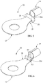
FIG. 2 is a perspective view of the electrical terminal with the wire inserted and terminated to the wire attachment portion. -
FIG. 3 is a perspective view of the electrical terminal ofFIG. 1 with the sealing sleeve positioned on the wire attachment portion and the sealing sleeve recovered. -
FIG. 4 is a cross-sectional view taken along line 4-4 ofFIG. 3 . -
FIG. 5 is a perspective view of an electrical terminal with a first alternate embodiment of the adhesive flow-out barrier provided thereon. -
FIG. 6 is a perspective view of an electrical terminal with a second alternate embodiment of the adhesive flow-out barrier provided thereon. - An embodiment is directed to an electrical terminal having a terminal attachment portion, a wire attachment portion and a transition portion. The wire attachment portion is configured to receive wires of a cable therein. The transition portion extends between the terminal attachment portion and the wire attachment portion. A flow barrier is provided on the transition portion proximate an end of the transition portion. The flow barrier constrains an adhesive/sealant applied to the wires positioned in the wire attachment portion from flowing from the wire attachment portion to the terminal attachment portion.
- An embodiment is directed to an assembly of an electrical terminal with a cable terminated thereto. The assembly includes the terminal which has a terminal attachment portion, a wire attachment portion for receiving the cable therein, and a transition portion which extends between the terminal attachment portion and the wire attachment portion. A flow barrier is provided on the transition portion proximate an end of the transition portion. The cable has wires and an insulation sleeve. A sealing device is provided on the cable and extends over the wire attachment portion of the terminal. The sealing device is a heat shrinkable tubing with an adhesive/sealant provided therein. The flow barrier constrains the adhesive/sealant from flowing from the wire attachment portion to the terminal attachment portion.
- An embodiment is directed to a method of terminating a cable to an electrical terminal. The method includes: positioning exposed wires of a cable in a wire attachment portion of the terminal; terminating the exposed wires to the wire attachment portion; moving a heat shrinkable sealing device over the exposed wires and the wire attachment portion, the heat shrinkable sealing device having adhesive/sealant retained therein; applying heat to the heat shrinkable sealing device causing the adhesive/sealant to flow around the exposed wires and causing the heat shrinkable sealing device to recover; and providing a flow barrier to prevent the adhesive/sealant from flowing from the wire attachment portion of the terminal to a terminal attachment portion of the terminal.
- With reference to the Figures,
FIG. 1 provides an illustration of anelectrical terminal 10 that is compatible with the systems, methods, and devices of the present invention. The electrical terminal shown inFIG. 1 is a ring-type terminal; however, the systems, methods, and devices of this invention are also compatible with many other types of electrical terminals such as, for example, spade terminals, hook terminals, flag terminals, push-on terminals, and the like. With reference toFIG. 1 ,electrical terminal 10 includesterminal attachment portion 12, awire attachment portion 14 and atransition portion 16 which extends between theterminal attachment portion 12 and thewire attachment portion 14. Theterminal attachment portion 12 is configured for connection to a complementary terminal, such as a stud or a post, of an electrical device such as, for example, a battery. Thewire attachment portion 14 is configured for connection to acable 18, such as, but not limited to, one or more electrical wires, which may be connected by welding, soldering, crimping or other suitable attachment methods. The particular configuration of theterminal 10 is shown for illustrative purposes. Theterminal attachment portion 12, thewire attachment portion 14 and thetransition portion 16 may have varied configurations without departing from the scope of the invention. - As best shown in
FIGS. 1 and 2 , thetransition portion 16 of theterminal 10 includes aflow barrier 20a. Theflow barrier 20a is positioned proximate to thewire attachment portion 14. Theflow barrier 20a extends from a first ortop surface 22 of thetransition portion 16 in a direction away from an oppositely facing second orbottom surface 24 of thetransition portion 16. Theflow barrier 20a extends from thetransition portion 16 in essentially the same direction as thewire attachment portion 14. Theflow barrier 20a extends from proximate afirst side surface 26 of thetransition portion 16 to proximate an opposedsecond side surface 28 of thetransition portion 16. - In the embodiment shown in
FIGS. 1 through 3 , theflow barrier 20a is a heat shrinkable sleeve which is positioned around thetransition portion 16. The heat shrinkable sleeve is positioned about thetransition portion 16 and heat is applied such that the heat shrinkable sleeve is recovered to form theflow barrier 20a. The heat shrinkable sleeve forms a seal with thetransition portion 16. This embodiment is an illustrative embodiment of the flow barrier being a separate part which is fixed or attached to the terminal. - In the embodiment shown in
FIG. 5 , theflow barrier 20b is an O-ring which is positioned around thetransition portion 16. The O-ring is positioned about thetransition portion 16 and conforms to thetransition portion 16 to form theflow barrier 20b. The O-ring is dimensioned to apply a compressive force to thetransition portion 16 when it is applied onto thetransition portion 16 to form a seal with thetransition portion 16. This embodiment is an illustrative embodiment of the flow barrier being a separate part which is positioned on the terminal. - In the embodiment shown in
FIG. 6 , theflow barrier 20c is a one or more dimples, peaks or shoulders stamped from thetransition portion 16. This embodiment is an illustrative embodiment of the flow barrier being integrally formed with the terminal. However, other configurations of the flow barrier may be used without departing from the scope of the invention. - In each of the illustrative embodiments, the
flow barrier first surface 22 of the transition portion 16 a distance H2 (FIG. 6 ) which is less than the height H1 of thewire attachment portion 14. In various illustrative embodiments, the height H2 of the flow barrier is less than one-half the height H1 of thewire attachment portion 14, the height H2 of the flow barrier is less than one-fourth of the height H1 of thewire attachment portion 14, the height H2 of the flow barrier is greater than one-fourth of the height H1 of thewire attachment portion 14, or the height H2 of the flow barrier is between one-half to one-fourth of the height H1 of thewire attachment portion 14. - In the embodiment shown, the
cable 18 has a plurality ofwires 30 with aninsulation sleeve 32. Thewires 30 are exposed at astriped end 34 of thecable 18. In the embodiment shown, threewires 30 are provided, however, other numbers of wires can be used. - As shown in
FIGS. 1 and 2 , a sealingsleeve 40 is provided on thecable 18. The sealingsleeve 40 includes a piece ofshrinkable tubing 42 with a sealant/adhesive 44 positioned inside. The sealant/adhesive 44 may be in the form of a ring, sleeve, full circular profile, semi-circular profile, or other profiled geometry. Theshrinkable tubing 42 can be a single layer or multilayer tubing. Theshrinkable tubing 42 may be a polymeric component that shrinks on the application of heat. Such shrinkable tubing may include, but is not limited to, heat shrinkable tubing or tape. The term sealant/adhesive includes, but is not limited to, sealants and adhesives which are viscoelastic materials that have an ability to flow under suitable stimulus like temperature and/or pressure. Examples of such materials are hot melt adhesives and butyl mastics. The sealant/adhesive 44 is placed within theshrinkable tubing 42 adjacent to or proximate aleading edge 46 of theshrinkable tubing 22. The sealant/adhesive 44 may be a high viscosity sealant/adhesive, such as, for example, sealant/adhesive which has a viscosity that is greater than 20 Pa·s at an installation temperature which correlates to a designated or rated temperature. The sealant/adhesive 44 may be a low viscosity sealant/adhesive, such as, for example, sealant/adhesive which has a viscosity that is less than 20 Pa·s at an installation temperature which correlates to a designated or rated temperature. The sealant/adhesive 44 may be a combination of low viscosity sealant/adhesive and high viscosity sealant/adhesive. The sealant/adhesive 44 has a flow behavior such that it conforms to the surface of the wire attachment portion or surface of the plurality of wires while allowing the sealant/adhesive 44 to displace air efficiently inside thecable 18 intended to be sealed to create a robust seal. - In use, exposed
wires 30 at the strippedend 34 of thecable 18 are moved into thewire attachment portion 14 of the terminal 10. The insertion of thewires 30 into thewire attachment portion 14 continues until a portion of thewires 30 engages the flow barrier of or attached to thetransition portion 16. The flow barrier provides a wire stop to prevent the further insertion of thewires 30 intowire attachment portion 14. This prevents thewires 30 from being inserted to theterminal attachment portion 12 and interfering therewith. - With the exposed
wires 30 properly positioned in thewire attachment portion 14 of the terminal 10, thewire attachment portion 14 is terminated to thewires 30, as shown inFIG. 2 . In the embodiment shown, thewire attachment portion 14 is crimped to the wires, but other methods of termination can be used. - With the exposed
wires 30 properly terminated to thewire attachment portion 14, the sealingsleeve 40 is moved over the exposedwires 30 and thewire attachment portion 14. Heat is then applied to the sealingsleeve 40. Upon the application of heat (e.g., in an infrared oven for 30 seconds or other time period) after installation of theshrinkable tubing 42 over theelectrical terminal 10, the sealant/adhesive 44 melts and flows across the exposedwires 30 of thecable 18 filling any present air voids. Theshrinkable tubing 42 shrinks to encapsulate the exposedwires 30 and thewire attachment portion 14 of the electrical terminal 10 (as shown inFIG. 3 ), thereby substantially sealing the melted sealant/adhesive 44 within theshrinkable tubing 40. - During the heating process, the flow barrier, which is positioned proximate the
leading edge 46 of theshrinkable tubing 22 cooperates with the sealant/adhesive 42 to block and effectively constrain the flow or oozing of the sealant/adhesive 42 in the direction of theterminal attachment portion 12, thereby reducing or preventing any problematic contamination of theterminal attachment portion 12 by the sealant/adhesive 42. While in some instances a small amount of sealant/adhesive 42 may travel onto theterminal attachment portion 12, the amount will be insignificant with regard to the functioning of theelectrical terminal 10. - During the heating process, the flow barrier also blocks and effectively constrains the flow or oozing of the sealant/adhesive 42 away from the exposed
wires 30 of thecable 18, thetransition portion 16 and thewire attachment portion 14. The retention of the sealant/adhesive 42 is the desired area allows the sealant/adhesive 42 to properly and evenly flow around the exposedwires 30, thetransition portion 16 and thewire attachment portion 14 to provide a proper seal. As shown inFIG. 4 , the sealant/adhesive 42 is provided around thewires 30 and around thetransition portion 16, including around thefirst surface 22, thesecond surface 24, thefirst side surface 26, thesecond side surface 28 and thecorners 29 provided therebetween. The controlled and even flow of the sealant/adhesive 42 prevents contaminants and/or water from affecting the electrical connection between thewires 30 and the terminal 10.
Claims (12)
- An electrical terminal (10), comprising:a terminal attachment portion (12);a wire attachment portion (14) for receiving wires (30) of a cable (18) therein;a transition portion (16) extending between the terminal attachment portion (12) and the wire attachment portion (14);a flow barrier (20a, 20b, 20c) provided on the transition portion (16) proximate an end of the transition portion (16);wherein the flow barrier (20a, 20b, 20c) constrains an adhesive/sealant (44) applied to the wires (30) positioned in the wire attachment portion (14) from flowing from the wire attachment portion (14) to the terminal attachment portion (12).
- The electrical terminal (10) as recited in claim 1, wherein the flow barrier (20c) is integrally formed with the terminal (10).
- The electrical terminal (10) as recited in claim 1 or 2, wherein the flow barrier (20c) is at least one dimple which extends from a top surface (22) of the transition portion (16).
- The electrical terminal (10) as recited in claim 1, wherein the flow barrier (20a, 20b) is a separate part from the terminal (10) which is fixed to the terminal (10).
- The electrical terminal (10) as recited in claim 4, wherein the flow barrier (20a) is a heat shrinkable sleeve.
- The electrical terminal (10) as recited in claim 1, wherein the flow barrier (20a, 20b) is a separate part from the terminal (10) which is positioned on the terminal (10).
- The electrical terminal (10) as recited in claim 4 or 6, wherein the flow barrier (20b) is an O-ring.
- The electrical terminal (10) as recited in any preceding claim, wherein the flow barrier (20a, 20b, 20c) acts as a wire stop to properly position the wires (30) in the wire attachment portion (14).
- The electrical terminal (10) as recited in any preceding claim, wherein the terminal (10) is a ring terminal.
- The electrical terminal (10) as recited in any preceding claim, wherein a height (H2) of the flow barrier (20a, 20b, 20c) is less than a height (H1) of the wire attachment portion (14).
- A method of terminating a cable to an electrical terminal (10), the method comprising:positioning exposed wires (30) of a cable (18) in a wire attachment portion (14) of the terminal (10);terminating the exposed wires (30) to the wire attachment portion (14);moving a heat shrinkable sealing device (40) over the exposed wires (30) and the wire attachment portion (14), the heat shrinkable sealing device (40) having adhesive/sealant (44) retained therein;applying heat to the heat shrinkable sealing device (40) causing the adhesive/sealant (44) to flow around the exposed wires (30) and causing the heat shrinkable sealing device (40) to recover; andproviding a flow barrier (20a, 20b, 20c) to prevent the adhesive/sealant (44) from flowing from the wire attachment portion (14) of the terminal (10) to a terminal attachment portion (12) of the terminal (10).
- The method as recited in claim 11, wherein the flow barrier (20a, 20b, 20c) acts as a wire stop to properly position the exposed wires (30) in the wire attachment portion (14).
Applications Claiming Priority (1)
| Application Number | Priority Date | Filing Date | Title |
|---|---|---|---|
| US16/553,734 US10819063B1 (en) | 2019-08-28 | 2019-08-28 | Sealed electric terminal with adhesive flow-out retarder |
Publications (2)
| Publication Number | Publication Date |
|---|---|
| EP3787124A1 true EP3787124A1 (en) | 2021-03-03 |
| EP3787124B1 EP3787124B1 (en) | 2024-10-16 |
Family
ID=72240360
Family Applications (1)
| Application Number | Title | Priority Date | Filing Date |
|---|---|---|---|
| EP20192631.8A Active EP3787124B1 (en) | 2019-08-28 | 2020-08-25 | Sealed electrical terminal with adhesive flow-out retarder |
Country Status (5)
| Country | Link |
|---|---|
| US (1) | US10819063B1 (en) |
| EP (1) | EP3787124B1 (en) |
| JP (1) | JP7662171B2 (en) |
| CN (1) | CN112448181A (en) |
| BR (1) | BR102020017540A2 (en) |
Families Citing this family (2)
| Publication number | Priority date | Publication date | Assignee | Title |
|---|---|---|---|---|
| US11424559B1 (en) * | 2021-05-07 | 2022-08-23 | GM Global Technology Operations LLC | Strain relief for battery cable terminals |
| EP4418465A1 (en) * | 2023-02-17 | 2024-08-21 | Intercable GmbH | Longitudinally water-tight cable contact |
Citations (7)
| Publication number | Priority date | Publication date | Assignee | Title |
|---|---|---|---|---|
| EP1528628A1 (en) * | 2003-10-31 | 2005-05-04 | Tyco Electronics Raychem K.K. | Waterproof type lead, method of manufacturing and jig for manufacturing it |
| EP1796216A1 (en) * | 2005-12-09 | 2007-06-13 | Delphi Technologies, Inc. | Cable shoe |
| JP2008176970A (en) * | 2007-01-17 | 2008-07-31 | Komatsu Ltd | Crimp terminal |
| US20130309903A1 (en) * | 2012-05-15 | 2013-11-21 | Sumitomo Wiring Systems, Ltd. | Crimp terminal |
| JP2014232619A (en) * | 2013-05-29 | 2014-12-11 | 株式会社オートネットワーク技術研究所 | Wire with terminal |
| JP2016184493A (en) * | 2015-03-26 | 2016-10-20 | 株式会社オートネットワーク技術研究所 | Electric wire with heat shrinkable tube |
| JP2016184512A (en) * | 2015-03-26 | 2016-10-20 | 株式会社フジクラ | Covered electric wire with terminal and method of manufacturing the same |
Family Cites Families (30)
| Publication number | Priority date | Publication date | Assignee | Title |
|---|---|---|---|---|
| GB8816291D0 (en) * | 1988-07-08 | 1988-08-10 | Raychem Ltd | Electrical terminal |
| US5137478A (en) * | 1991-04-01 | 1992-08-11 | National Standard Parts, Inc. | Sealed solder wire connector assembly and method of use |
| US6015953A (en) * | 1994-03-11 | 2000-01-18 | Tohoku Electric Power Co., Inc. | Tension clamp for stranded conductor |
| JP3214393B2 (en) * | 1997-04-16 | 2001-10-02 | 住友電装株式会社 | Ground terminal fitting |
| DE19948819C2 (en) * | 1999-10-09 | 2002-01-24 | Airbus Gmbh | Heating conductor with a connection element and / or a termination element and a method for producing the same |
| JP2001167640A (en) * | 1999-12-09 | 2001-06-22 | Yazaki Corp | Terminal connection part of insulated wire and waterproofing device therefor |
| US20030026053A1 (en) * | 2001-08-06 | 2003-02-06 | James Toth | Circuit protection device |
| JP2005005042A (en) * | 2003-06-10 | 2005-01-06 | Jst Mfg Co Ltd | Cable with waterproof plug, connector cable with waterproof plug, manufacturing method of cable with waterproof plug, and terminal fitting connection structure of cable with waterproof plug |
| US7354283B2 (en) * | 2005-09-29 | 2008-04-08 | Yazaki Corporation | Wire-connecting device |
| EP2255411B1 (en) * | 2008-02-21 | 2015-07-01 | Melni LLC | Electrical connector |
| US8066525B2 (en) * | 2008-02-21 | 2011-11-29 | Melni Mark L | Electrical connectors and methods of manufacturing and using same |
| US8262408B1 (en) * | 2008-10-22 | 2012-09-11 | Distinct Intuitive Designs, LLC | Coaxial cable assembly connection structure and method |
| US9385449B2 (en) * | 2009-02-16 | 2016-07-05 | Carlisle Interconnect Technologies, Inc. | Terminal/connector having integral oxide breaker element |
| US20110177727A1 (en) * | 2010-01-18 | 2011-07-21 | Weiping Zhao | Aluminum conductor and conductive terminal connection |
| JP5800590B2 (en) * | 2011-06-17 | 2015-10-28 | 矢崎総業株式会社 | Wire connection terminal and wire harness provided with the wire connection terminal |
| JP2013109847A (en) * | 2011-11-17 | 2013-06-06 | Yazaki Corp | Core wire water cut-off structure and core wire water cut-off method |
| JP6044509B2 (en) * | 2013-11-01 | 2016-12-14 | 住友電装株式会社 | Water stop structure of wire harness |
| US9356438B2 (en) * | 2014-02-27 | 2016-05-31 | Delphi Technologies, Inc. | Wire cable assembly having a terminal with an encapsulated wire end |
| JP2016048615A (en) * | 2014-08-27 | 2016-04-07 | 住友電装株式会社 | Wire Harness |
| US9936617B2 (en) * | 2015-03-24 | 2018-04-03 | Yazaki North America, Inc. | Electromagnetic interference splice shield |
| US10439384B2 (en) * | 2015-04-28 | 2019-10-08 | Sumitomo Electric Industries, Ltd. | Heat-recoverable article, method for manufacturing heat-recoverable article, wire splice, and wire harness |
| JP2017027884A (en) * | 2015-07-27 | 2017-02-02 | 株式会社オートネットワーク技術研究所 | Terminal fitting, electric wire with terminal, and method of manufacturing electric wire with terminal |
| DE102015219654A1 (en) * | 2015-10-09 | 2017-04-13 | Te Connectivity Germany Gmbh | Connection arrangement with foamed sealing material, electrical connection element and electrical line with foamable sealing material and method for sealing the connection of an electrical conductor with an electrical connection element |
| JP2017174643A (en) * | 2016-03-24 | 2017-09-28 | 株式会社オートネットワーク技術研究所 | Heat-shrinkable tube-equipped wire, manufacturing method of heat-shrinkable tube-equipped wire, and heat-shrinkable tube fitting jig |
| US9601866B1 (en) * | 2016-07-11 | 2017-03-21 | Elemental LED, Inc. | Strain relief and joint support |
| JP6782150B2 (en) * | 2016-11-07 | 2020-11-11 | 古河電気工業株式会社 | Manufacturing method of electric wire with terminal |
| US10109947B2 (en) * | 2017-02-07 | 2018-10-23 | Te Connectivity Corporation | System and method for sealing electrical terminals |
| US10483661B2 (en) * | 2017-02-07 | 2019-11-19 | Te Connectivity Corporation | System and method for sealing electrical terminals |
| US10103458B2 (en) * | 2017-02-07 | 2018-10-16 | Te Connectivity Corporation | System and method for sealing electrical terminals |
| US10312604B2 (en) * | 2017-06-07 | 2019-06-04 | Hitachi Metals, Ltd. | Crimping terminal and electric wire with crimping terminal |
-
2019
- 2019-08-28 US US16/553,734 patent/US10819063B1/en active Active
-
2020
- 2020-08-25 EP EP20192631.8A patent/EP3787124B1/en active Active
- 2020-08-25 JP JP2020141380A patent/JP7662171B2/en active Active
- 2020-08-26 CN CN202010868485.1A patent/CN112448181A/en active Pending
- 2020-08-27 BR BR102020017540-8A patent/BR102020017540A2/en unknown
Patent Citations (7)
| Publication number | Priority date | Publication date | Assignee | Title |
|---|---|---|---|---|
| EP1528628A1 (en) * | 2003-10-31 | 2005-05-04 | Tyco Electronics Raychem K.K. | Waterproof type lead, method of manufacturing and jig for manufacturing it |
| EP1796216A1 (en) * | 2005-12-09 | 2007-06-13 | Delphi Technologies, Inc. | Cable shoe |
| JP2008176970A (en) * | 2007-01-17 | 2008-07-31 | Komatsu Ltd | Crimp terminal |
| US20130309903A1 (en) * | 2012-05-15 | 2013-11-21 | Sumitomo Wiring Systems, Ltd. | Crimp terminal |
| JP2014232619A (en) * | 2013-05-29 | 2014-12-11 | 株式会社オートネットワーク技術研究所 | Wire with terminal |
| JP2016184493A (en) * | 2015-03-26 | 2016-10-20 | 株式会社オートネットワーク技術研究所 | Electric wire with heat shrinkable tube |
| JP2016184512A (en) * | 2015-03-26 | 2016-10-20 | 株式会社フジクラ | Covered electric wire with terminal and method of manufacturing the same |
Also Published As
| Publication number | Publication date |
|---|---|
| JP7662171B2 (en) | 2025-04-15 |
| US10819063B1 (en) | 2020-10-27 |
| JP2021034383A (en) | 2021-03-01 |
| BR102020017540A2 (en) | 2021-03-09 |
| EP3787124B1 (en) | 2024-10-16 |
| CN112448181A (en) | 2021-03-05 |
Similar Documents
| Publication | Publication Date | Title |
|---|---|---|
| CN104882688B (en) | CA cable assembly with the terminal with encapsulation wire end | |
| US6359226B1 (en) | Device and method for protecting and sealing exposed wires | |
| JP5800590B2 (en) | Wire connection terminal and wire harness provided with the wire connection terminal | |
| EP0270283A2 (en) | Solder connection device | |
| EP3787124B1 (en) | Sealed electrical terminal with adhesive flow-out retarder | |
| JP6816299B2 (en) | Systems and methods for sealing electrical terminals | |
| US10109947B2 (en) | System and method for sealing electrical terminals | |
| US10483661B2 (en) | System and method for sealing electrical terminals | |
| US10297946B1 (en) | Apparatus and methods for sealing electrical connections | |
| US11677171B2 (en) | System and method for sealing electrical terminals | |
| JP2017073312A (en) | Wire with terminal and heat shrinkable tubing | |
| KR830001743B1 (en) | Branch seal formation method | |
| WO2020016699A1 (en) | System and method for sealing electrical terminals | |
| CA1286485C (en) | Branch-off clip | |
| JP2013062213A (en) | Electric wire with terminal fitting, method for manufacturing the same, and waterproof wall |
Legal Events
| Date | Code | Title | Description |
|---|---|---|---|
| PUAI | Public reference made under article 153(3) epc to a published international application that has entered the european phase |
Free format text: ORIGINAL CODE: 0009012 |
|
| STAA | Information on the status of an ep patent application or granted ep patent |
Free format text: STATUS: REQUEST FOR EXAMINATION WAS MADE |
|
| 17P | Request for examination filed |
Effective date: 20200825 |
|
| AK | Designated contracting states |
Kind code of ref document: A1 Designated state(s): AL AT BE BG CH CY CZ DE DK EE ES FI FR GB GR HR HU IE IS IT LI LT LU LV MC MK MT NL NO PL PT RO RS SE SI SK SM TR |
|
| AX | Request for extension of the european patent |
Extension state: BA ME |
|
| STAA | Information on the status of an ep patent application or granted ep patent |
Free format text: STATUS: EXAMINATION IS IN PROGRESS |
|
| 17Q | First examination report despatched |
Effective date: 20221013 |
|
| RAP1 | Party data changed (applicant data changed or rights of an application transferred) |
Owner name: TE CONNECTIVITY SOLUTIONS GMBH |
|
| GRAP | Despatch of communication of intention to grant a patent |
Free format text: ORIGINAL CODE: EPIDOSNIGR1 |
|
| STAA | Information on the status of an ep patent application or granted ep patent |
Free format text: STATUS: GRANT OF PATENT IS INTENDED |
|
| RIC1 | Information provided on ipc code assigned before grant |
Ipc: H01R 4/20 20060101ALN20240517BHEP Ipc: H01R 4/02 20060101ALN20240517BHEP Ipc: H02G 15/04 20060101ALI20240517BHEP Ipc: H01R 11/12 20060101ALI20240517BHEP Ipc: H01R 4/72 20060101AFI20240517BHEP |
|
| INTG | Intention to grant announced |
Effective date: 20240605 |
|
| GRAS | Grant fee paid |
Free format text: ORIGINAL CODE: EPIDOSNIGR3 |
|
| GRAA | (expected) grant |
Free format text: ORIGINAL CODE: 0009210 |
|
| STAA | Information on the status of an ep patent application or granted ep patent |
Free format text: STATUS: THE PATENT HAS BEEN GRANTED |
|
| AK | Designated contracting states |
Kind code of ref document: B1 Designated state(s): AL AT BE BG CH CY CZ DE DK EE ES FI FR GB GR HR HU IE IS IT LI LT LU LV MC MK MT NL NO PL PT RO RS SE SI SK SM TR |
|
| REG | Reference to a national code |
Ref country code: GB Ref legal event code: FG4D |
|
| REG | Reference to a national code |
Ref country code: CH Ref legal event code: EP |
|
| REG | Reference to a national code |
Ref country code: IE Ref legal event code: FG4D |
|
| REG | Reference to a national code |
Ref country code: DE Ref legal event code: R096 Ref document number: 602020039451 Country of ref document: DE |
|
| REG | Reference to a national code |
Ref country code: LT Ref legal event code: MG9D |
|
| REG | Reference to a national code |
Ref country code: NL Ref legal event code: MP Effective date: 20241016 |
|
| REG | Reference to a national code |
Ref country code: AT Ref legal event code: MK05 Ref document number: 1733716 Country of ref document: AT Kind code of ref document: T Effective date: 20241016 |
|
| PG25 | Lapsed in a contracting state [announced via postgrant information from national office to epo] |
Ref country code: NL Free format text: LAPSE BECAUSE OF FAILURE TO SUBMIT A TRANSLATION OF THE DESCRIPTION OR TO PAY THE FEE WITHIN THE PRESCRIBED TIME-LIMIT Effective date: 20241016 |
|
| PG25 | Lapsed in a contracting state [announced via postgrant information from national office to epo] |
Ref country code: NL Free format text: LAPSE BECAUSE OF FAILURE TO SUBMIT A TRANSLATION OF THE DESCRIPTION OR TO PAY THE FEE WITHIN THE PRESCRIBED TIME-LIMIT Effective date: 20241016 |
|
| PG25 | Lapsed in a contracting state [announced via postgrant information from national office to epo] |
Ref country code: IS Free format text: LAPSE BECAUSE OF FAILURE TO SUBMIT A TRANSLATION OF THE DESCRIPTION OR TO PAY THE FEE WITHIN THE PRESCRIBED TIME-LIMIT Effective date: 20250216 Ref country code: PT Free format text: LAPSE BECAUSE OF FAILURE TO SUBMIT A TRANSLATION OF THE DESCRIPTION OR TO PAY THE FEE WITHIN THE PRESCRIBED TIME-LIMIT Effective date: 20250217 Ref country code: HR Free format text: LAPSE BECAUSE OF FAILURE TO SUBMIT A TRANSLATION OF THE DESCRIPTION OR TO PAY THE FEE WITHIN THE PRESCRIBED TIME-LIMIT Effective date: 20241016 |
|
| PG25 | Lapsed in a contracting state [announced via postgrant information from national office to epo] |
Ref country code: FI Free format text: LAPSE BECAUSE OF FAILURE TO SUBMIT A TRANSLATION OF THE DESCRIPTION OR TO PAY THE FEE WITHIN THE PRESCRIBED TIME-LIMIT Effective date: 20241016 |
|
| PG25 | Lapsed in a contracting state [announced via postgrant information from national office to epo] |
Ref country code: BG Free format text: LAPSE BECAUSE OF FAILURE TO SUBMIT A TRANSLATION OF THE DESCRIPTION OR TO PAY THE FEE WITHIN THE PRESCRIBED TIME-LIMIT Effective date: 20241016 |
|
| PG25 | Lapsed in a contracting state [announced via postgrant information from national office to epo] |
Ref country code: ES Free format text: LAPSE BECAUSE OF FAILURE TO SUBMIT A TRANSLATION OF THE DESCRIPTION OR TO PAY THE FEE WITHIN THE PRESCRIBED TIME-LIMIT Effective date: 20241016 |
|
| PG25 | Lapsed in a contracting state [announced via postgrant information from national office to epo] |
Ref country code: NO Free format text: LAPSE BECAUSE OF FAILURE TO SUBMIT A TRANSLATION OF THE DESCRIPTION OR TO PAY THE FEE WITHIN THE PRESCRIBED TIME-LIMIT Effective date: 20250116 |
|
| PG25 | Lapsed in a contracting state [announced via postgrant information from national office to epo] |
Ref country code: LV Free format text: LAPSE BECAUSE OF FAILURE TO SUBMIT A TRANSLATION OF THE DESCRIPTION OR TO PAY THE FEE WITHIN THE PRESCRIBED TIME-LIMIT Effective date: 20241016 Ref country code: GR Free format text: LAPSE BECAUSE OF FAILURE TO SUBMIT A TRANSLATION OF THE DESCRIPTION OR TO PAY THE FEE WITHIN THE PRESCRIBED TIME-LIMIT Effective date: 20250117 Ref country code: AT Free format text: LAPSE BECAUSE OF FAILURE TO SUBMIT A TRANSLATION OF THE DESCRIPTION OR TO PAY THE FEE WITHIN THE PRESCRIBED TIME-LIMIT Effective date: 20241016 |
|
| PG25 | Lapsed in a contracting state [announced via postgrant information from national office to epo] |
Ref country code: PL Free format text: LAPSE BECAUSE OF FAILURE TO SUBMIT A TRANSLATION OF THE DESCRIPTION OR TO PAY THE FEE WITHIN THE PRESCRIBED TIME-LIMIT Effective date: 20241016 |
|
| PG25 | Lapsed in a contracting state [announced via postgrant information from national office to epo] |
Ref country code: RS Free format text: LAPSE BECAUSE OF FAILURE TO SUBMIT A TRANSLATION OF THE DESCRIPTION OR TO PAY THE FEE WITHIN THE PRESCRIBED TIME-LIMIT Effective date: 20250116 |
|
| PG25 | Lapsed in a contracting state [announced via postgrant information from national office to epo] |
Ref country code: SM Free format text: LAPSE BECAUSE OF FAILURE TO SUBMIT A TRANSLATION OF THE DESCRIPTION OR TO PAY THE FEE WITHIN THE PRESCRIBED TIME-LIMIT Effective date: 20241016 |
|
| PG25 | Lapsed in a contracting state [announced via postgrant information from national office to epo] |
Ref country code: DK Free format text: LAPSE BECAUSE OF FAILURE TO SUBMIT A TRANSLATION OF THE DESCRIPTION OR TO PAY THE FEE WITHIN THE PRESCRIBED TIME-LIMIT Effective date: 20241016 |
|
| REG | Reference to a national code |
Ref country code: DE Ref legal event code: R097 Ref document number: 602020039451 Country of ref document: DE |
|
| PG25 | Lapsed in a contracting state [announced via postgrant information from national office to epo] |
Ref country code: EE Free format text: LAPSE BECAUSE OF FAILURE TO SUBMIT A TRANSLATION OF THE DESCRIPTION OR TO PAY THE FEE WITHIN THE PRESCRIBED TIME-LIMIT Effective date: 20241016 |
|
| PG25 | Lapsed in a contracting state [announced via postgrant information from national office to epo] |
Ref country code: RO Free format text: LAPSE BECAUSE OF FAILURE TO SUBMIT A TRANSLATION OF THE DESCRIPTION OR TO PAY THE FEE WITHIN THE PRESCRIBED TIME-LIMIT Effective date: 20241016 |
|
| PG25 | Lapsed in a contracting state [announced via postgrant information from national office to epo] |
Ref country code: SK Free format text: LAPSE BECAUSE OF FAILURE TO SUBMIT A TRANSLATION OF THE DESCRIPTION OR TO PAY THE FEE WITHIN THE PRESCRIBED TIME-LIMIT Effective date: 20241016 |
|
| PG25 | Lapsed in a contracting state [announced via postgrant information from national office to epo] |
Ref country code: CZ Free format text: LAPSE BECAUSE OF FAILURE TO SUBMIT A TRANSLATION OF THE DESCRIPTION OR TO PAY THE FEE WITHIN THE PRESCRIBED TIME-LIMIT Effective date: 20241016 |
|
| PG25 | Lapsed in a contracting state [announced via postgrant information from national office to epo] |
Ref country code: IT Free format text: LAPSE BECAUSE OF FAILURE TO SUBMIT A TRANSLATION OF THE DESCRIPTION OR TO PAY THE FEE WITHIN THE PRESCRIBED TIME-LIMIT Effective date: 20241016 |
|
| PLBE | No opposition filed within time limit |
Free format text: ORIGINAL CODE: 0009261 |
|
| STAA | Information on the status of an ep patent application or granted ep patent |
Free format text: STATUS: NO OPPOSITION FILED WITHIN TIME LIMIT |
|
| PG25 | Lapsed in a contracting state [announced via postgrant information from national office to epo] |
Ref country code: SE Free format text: LAPSE BECAUSE OF FAILURE TO SUBMIT A TRANSLATION OF THE DESCRIPTION OR TO PAY THE FEE WITHIN THE PRESCRIBED TIME-LIMIT Effective date: 20241016 |
|
| 26N | No opposition filed |
Effective date: 20250717 |
|
| PGFP | Annual fee paid to national office [announced via postgrant information from national office to epo] |
Ref country code: DE Payment date: 20250702 Year of fee payment: 6 |
|
| PGFP | Annual fee paid to national office [announced via postgrant information from national office to epo] |
Ref country code: GB Payment date: 20250703 Year of fee payment: 6 |
|
| PGFP | Annual fee paid to national office [announced via postgrant information from national office to epo] |
Ref country code: FR Payment date: 20250703 Year of fee payment: 6 |
|
| REG | Reference to a national code |
Ref country code: CH Ref legal event code: H13 Free format text: ST27 STATUS EVENT CODE: U-0-0-H10-H13 (AS PROVIDED BY THE NATIONAL OFFICE) Effective date: 20260324 |
|
| PG25 | Lapsed in a contracting state [announced via postgrant information from national office to epo] |
Ref country code: MC Free format text: LAPSE BECAUSE OF FAILURE TO SUBMIT A TRANSLATION OF THE DESCRIPTION OR TO PAY THE FEE WITHIN THE PRESCRIBED TIME-LIMIT Effective date: 20241016 |
|
| PG25 | Lapsed in a contracting state [announced via postgrant information from national office to epo] |
Ref country code: LU Free format text: LAPSE BECAUSE OF NON-PAYMENT OF DUE FEES Effective date: 20250825 |
|
| PG25 | Lapsed in a contracting state [announced via postgrant information from national office to epo] |
Ref country code: CH Free format text: LAPSE BECAUSE OF NON-PAYMENT OF DUE FEES Effective date: 20250831 |
|
| REG | Reference to a national code |
Ref country code: BE Ref legal event code: MM Effective date: 20250831 |
|
| PG25 | Lapsed in a contracting state [announced via postgrant information from national office to epo] |
Ref country code: LT Free format text: LAPSE BECAUSE OF FAILURE TO SUBMIT A TRANSLATION OF THE DESCRIPTION OR TO PAY THE FEE WITHIN THE PRESCRIBED TIME-LIMIT Effective date: 20241016 |
|
| PG25 | Lapsed in a contracting state [announced via postgrant information from national office to epo] |
Ref country code: IE Free format text: LAPSE BECAUSE OF NON-PAYMENT OF DUE FEES Effective date: 20250825 Ref country code: BE Free format text: LAPSE BECAUSE OF NON-PAYMENT OF DUE FEES Effective date: 20250831 |