EP3786938A1 - Display device and a method of operation - Google Patents
Display device and a method of operation Download PDFInfo
- Publication number
- EP3786938A1 EP3786938A1 EP19194413.1A EP19194413A EP3786938A1 EP 3786938 A1 EP3786938 A1 EP 3786938A1 EP 19194413 A EP19194413 A EP 19194413A EP 3786938 A1 EP3786938 A1 EP 3786938A1
- Authority
- EP
- European Patent Office
- Prior art keywords
- display elements
- test pattern
- display
- emissive
- power consumption
- Prior art date
- Legal status (The legal status is an assumption and is not a legal conclusion. Google has not performed a legal analysis and makes no representation as to the accuracy of the status listed.)
- Withdrawn
Links
- 238000000034 method Methods 0.000 title claims description 40
- 238000012360 testing method Methods 0.000 claims abstract description 83
- 230000014759 maintenance of location Effects 0.000 claims description 27
- 230000008569 process Effects 0.000 claims description 12
- 238000012545 processing Methods 0.000 claims description 6
- 230000000977 initiatory effect Effects 0.000 claims description 5
- 238000001792 White test Methods 0.000 description 7
- 238000004590 computer program Methods 0.000 description 5
- 230000032683 aging Effects 0.000 description 4
- 238000013500 data storage Methods 0.000 description 3
- 230000015654 memory Effects 0.000 description 3
- 239000004065 semiconductor Substances 0.000 description 3
- 230000009471 action Effects 0.000 description 2
- 230000000593 degrading effect Effects 0.000 description 2
- 238000004519 manufacturing process Methods 0.000 description 2
- 238000005259 measurement Methods 0.000 description 2
- 210000004180 plasmocyte Anatomy 0.000 description 2
- 230000003068 static effect Effects 0.000 description 2
- 230000003936 working memory Effects 0.000 description 2
- 241001085205 Prenanthella exigua Species 0.000 description 1
- 230000000694 effects Effects 0.000 description 1
- 230000006870 function Effects 0.000 description 1
- 238000013101 initial test Methods 0.000 description 1
- 230000002452 interceptive effect Effects 0.000 description 1
- 239000000463 material Substances 0.000 description 1
- 238000012986 modification Methods 0.000 description 1
- 230000004048 modification Effects 0.000 description 1
- 230000003287 optical effect Effects 0.000 description 1
- 230000004044 response Effects 0.000 description 1
- 239000000126 substance Substances 0.000 description 1
- 230000002618 waking effect Effects 0.000 description 1
Images
Classifications
-
- G—PHYSICS
- G09—EDUCATION; CRYPTOGRAPHY; DISPLAY; ADVERTISING; SEALS
- G09G—ARRANGEMENTS OR CIRCUITS FOR CONTROL OF INDICATING DEVICES USING STATIC MEANS TO PRESENT VARIABLE INFORMATION
- G09G3/00—Control arrangements or circuits, of interest only in connection with visual indicators other than cathode-ray tubes
- G09G3/20—Control arrangements or circuits, of interest only in connection with visual indicators other than cathode-ray tubes for presentation of an assembly of a number of characters, e.g. a page, by composing the assembly by combination of individual elements arranged in a matrix no fixed position being assigned to or needed to be assigned to the individual characters or partial characters
- G09G3/22—Control arrangements or circuits, of interest only in connection with visual indicators other than cathode-ray tubes for presentation of an assembly of a number of characters, e.g. a page, by composing the assembly by combination of individual elements arranged in a matrix no fixed position being assigned to or needed to be assigned to the individual characters or partial characters using controlled light sources
- G09G3/30—Control arrangements or circuits, of interest only in connection with visual indicators other than cathode-ray tubes for presentation of an assembly of a number of characters, e.g. a page, by composing the assembly by combination of individual elements arranged in a matrix no fixed position being assigned to or needed to be assigned to the individual characters or partial characters using controlled light sources using electroluminescent panels
- G09G3/32—Control arrangements or circuits, of interest only in connection with visual indicators other than cathode-ray tubes for presentation of an assembly of a number of characters, e.g. a page, by composing the assembly by combination of individual elements arranged in a matrix no fixed position being assigned to or needed to be assigned to the individual characters or partial characters using controlled light sources using electroluminescent panels semiconductive, e.g. using light-emitting diodes [LED]
- G09G3/3208—Control arrangements or circuits, of interest only in connection with visual indicators other than cathode-ray tubes for presentation of an assembly of a number of characters, e.g. a page, by composing the assembly by combination of individual elements arranged in a matrix no fixed position being assigned to or needed to be assigned to the individual characters or partial characters using controlled light sources using electroluminescent panels semiconductive, e.g. using light-emitting diodes [LED] organic, e.g. using organic light-emitting diodes [OLED]
-
- G—PHYSICS
- G09—EDUCATION; CRYPTOGRAPHY; DISPLAY; ADVERTISING; SEALS
- G09G—ARRANGEMENTS OR CIRCUITS FOR CONTROL OF INDICATING DEVICES USING STATIC MEANS TO PRESENT VARIABLE INFORMATION
- G09G3/00—Control arrangements or circuits, of interest only in connection with visual indicators other than cathode-ray tubes
- G09G3/20—Control arrangements or circuits, of interest only in connection with visual indicators other than cathode-ray tubes for presentation of an assembly of a number of characters, e.g. a page, by composing the assembly by combination of individual elements arranged in a matrix no fixed position being assigned to or needed to be assigned to the individual characters or partial characters
-
- G—PHYSICS
- G09—EDUCATION; CRYPTOGRAPHY; DISPLAY; ADVERTISING; SEALS
- G09G—ARRANGEMENTS OR CIRCUITS FOR CONTROL OF INDICATING DEVICES USING STATIC MEANS TO PRESENT VARIABLE INFORMATION
- G09G2320/00—Control of display operating conditions
- G09G2320/02—Improving the quality of display appearance
- G09G2320/0257—Reduction of after-image effects
-
- G—PHYSICS
- G09—EDUCATION; CRYPTOGRAPHY; DISPLAY; ADVERTISING; SEALS
- G09G—ARRANGEMENTS OR CIRCUITS FOR CONTROL OF INDICATING DEVICES USING STATIC MEANS TO PRESENT VARIABLE INFORMATION
- G09G2320/00—Control of display operating conditions
- G09G2320/04—Maintaining the quality of display appearance
- G09G2320/043—Preventing or counteracting the effects of ageing
- G09G2320/046—Dealing with screen burn-in prevention or compensation of the effects thereof
-
- G—PHYSICS
- G09—EDUCATION; CRYPTOGRAPHY; DISPLAY; ADVERTISING; SEALS
- G09G—ARRANGEMENTS OR CIRCUITS FOR CONTROL OF INDICATING DEVICES USING STATIC MEANS TO PRESENT VARIABLE INFORMATION
- G09G2330/00—Aspects of power supply; Aspects of display protection and defect management
- G09G2330/10—Dealing with defective pixels
Definitions
- the present disclosure relates to a display device and a method of operating a display device.
- a method of operating a display device comprising a display screen having a plurality of emissive display elements, the method comprising:
- the threshold may be a percentage difference in values, such as more than 0.1% or more than 0.2% or more than 0.5% or more than 1%, etc.
- the threshold may be an absolute value, such as a certain number of Watts.
- the method comprises initiating a process to fix image retention if it is determined that at least one of the emissive display elements is faulty and causing image retention.
- the determining that at least one of the emissive display elements is faulty may determine that at least one of the emissive display elements is causing image retention (or image "sticking"). This can occur because of so-called “burn-in” or ageing of one or more of the emissive display elements.
- image retention or image "sticking”
- Various methods for fixing image retention in emissive displays are known.
- the test pattern comprises at least one of a white image and a black image.
- the test pattern such as a white image and/or a black image, may cover the whole display screen so as effectively to test all of the emissive display elements simultaneously.
- the initially powering the emissive display elements to display a test pattern on the display screen takes place when the display device is first powered up or first powered down.
- This first powering up/down may take place when the display device is first powered up/down as a final manufacturing step, by for example the manufacturer as a "one-off' step.
- the initial value for power consumption of the emissive display elements may be stored in permanent storage on the display device in such a case.
- the first powering up/down may take place when the display device is first powered up/down by a user. This may be carried out for example as a "one-off' step when the display device is first used by the user.
- subsequently powering the emissive display elements to display the same test pattern on the display screen again takes place when the display device is subsequently powered up or subsequently powered down by a user.
- This subsequently powering up/down may take place every time the user powers up/down the display device, or every nth time the user powers up/down the display device where n is an integer greater than 1.
- the emissive display elements are powered to display a test pattern on the display screen with a refresh rate equal to or greater than 100 Hz. In an example, the emissive display elements are powered to display a test pattern on the display screen for one cycle of the refresh rate, such that the emissive display elements are powered for 0.01 seconds or less when displaying the test pattern.
- the emissive display elements are powered for 0.1 seconds or less when displaying the test pattern.
- the emissive display elements are organic light emitting diodes.
- a display device comprising:
- the processing system may comprise at least one processor and at least one memory including computer program instructions, the at least one memory and the computer program instructions being configured, with the at least one processor, to cause the display device at least to perform a method as described above.
- OLED organic light emitting diode
- Image retention can occur because for example a static image has been displayed for a (relatively) long time by the display device. This is exacerbated if the image is a bright image.
- the display elements can effectively degrade over time. This can mean that the brightness output by the display element for a certain voltage is lowered every time the display element is driven to output light. This is a particular problem with OLEDs.
- this degrading of the display element affects different colour display elements differently (where the "colour" of a display element is the colour of light that is output by the display element). Again, this is a particular problem with OLEDs. For example, some studies have shown that a red "sub-pixel" is the fastest to degrade, followed by blue sub-pixels and then green sub-pixels.
- Examples described herein enable faulty emissive display elements of a display device to be detected in an automated manner, which does not require any manual input by a user. In short, this is based on initially measuring power consumption by the display device and comparing power consumption at later times with the initial power consumption. If one or more faulty emissive display elements are detected, action can be initiated to address this. For example, a process to fix image retention can be initiated if it is determined that at least one of the emissive display elements is faulty and causing image retention. As mentioned, a number of techniques are known for dealing with and attempting to fix image retention if it does occur and one or more of these can be applied as necessary.
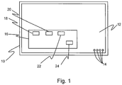
- Figure 1 shows schematically an example of a display device 10 having emissive display elements according to an aspect described herein.
- the display device 10 of this example is a television set.
- aspects described herein can also be applied to other display devices having emissive display elements, including for example computer displays or monitors, smartphones, tablet computers, laptop computers, etc., display devices used as so-called “signage", etc.
- the display device 10 has a display screen 12.
- the display screen 12 has a number of emissive display elements 14, only some of which are shown in Figure 1 .
- the emissive display elements 14 are OLEDs (organic light emitting diodes).
- the emissive display elements 14 are plasma cells as used in plasma displays.
- the number of display elements 14 depends principally on the resolution of the display screen 12, that is the number of "pixels" of the display screen 12. As is known, at each pixel, there may in fact be plural display elements, commonly referred to as "sub-pixels".
- each pixel there may be a red, a green and a blue "sub-pixel" at each pixel, each of which is an emissive display element 14 which respectively outputs red, green and blue light.
- the display device 10 has a mainboard 16 for controlling the display device 10 and other functions.
- the mainboard 16 has the usual processor 18, working memory 20 and data storage 22.
- the processor 18 controls operation of the display device 10 in accordance with software (one or more computer programs) stored in the data storage 22 and executed by the processor 18 using the working memory 20. Whilst a single processor 18 is shown for controlling the entire operation of the display device 10, there may be plural processors for controlling different aspects of the display device 10, and/or there may be additional circuity for controlling different aspects.
- a display power component 24 which provides power to the display elements 14 as required to generate an image on the display screen 12.
- the display device 10 operates to detect the presence of one or more faulty display elements 14 by displaying a test pattern on the display screen 12 and measuring the power consumption of the display elements 14. This is done initially, effectively to obtain an initial, reference value for the power consumption. This is then carried out later, during normal use of the display device 10, to obtain one or more subsequent values for the power consumption. The initial and subsequent values for the power consumption are compared and if they differ (by more than a threshold), then it is determined that one or more of the display elements 14 is faulty. This may be a determination that the one or more of the display elements 14 is causing image retention. In such a case, in an example the display device 10 can then initiate a process to fix the image retention. In an example, this can all be done automatically, requiring no manual user input.
- the test pattern may be an all black image.
- the display elements 14 are not driven or powered at all or are only driven with a minimum drive current and voltage, so that the display elements 14 emit no light or only a minimum amount of light.
- the initial, reference value for the power consumption of the display elements 14 will be a minimum.
- one or more of the display elements 14 may develop a fault (which may simply be through ageing, as known to occur for OLEDs in particular).
- the display device 10 cannot turn down the power consumption of the faulty display element(s) 14, such that the overall power consumption of the display elements 14, and indeed of the display device 10 as a whole, is different when the black test pattern is displayed again.
- the power consumption of the display elements 14, and indeed of the display device 10 as a whole is now greater than when the test pattern was initially displayed and all display elements 14 were working correctly. That is:
- the test pattern may be an all white image.
- the display elements 14 are driven with a maximum power so that the display elements 14 emit a maximum amount of light.
- the display elements 14 are sub-pixels, then, being white light, this means that all sub-pixels are driven with a maximum power.
- the initial, reference value for the power consumption of the display elements 14 will be a maximum.
- one or more of the display elements 14 may develop a fault (which, again, may simply be through ageing, as known to occur for OLEDs in particular).
- the white test pattern is displayed again, the overall power consumption of the display elements 14, and indeed of the display device 10 as a whole, is different.
- the power consumption of the display elements 14, and indeed of the display device 10 as a whole is now less than when the test pattern was initially displayed and all display elements 14 were working correctly. That is:
- the display device 10 may use only a black test pattern or only a white test pattern.
- the display device 10 may use a black test pattern and a white test pattern.
- the display device 10 may for example alternate the use of the black and white test patterns, or use a black test pattern a predetermined number of times followed by using a white test pattern a predetermined number of times, or use other variations.
- a threshold difference may be applied for this such that it is only determined that one or more of the display elements 14 is faulty if the initial and subsequent values for the power consumption differ by more than a threshold.
- the threshold may be a percentage difference in values, such as a difference of more than 0.1% or more than 0.2% or more than 0.5% or more than 1%, etc.
- the threshold may be an absolute value, such as a difference of a certain number of Watts. It is straightforward to determine appropriate values for the percentage difference or absolute difference by appropriate testing of the display device 10. The appropriate threshold will in general be different for different display devices 10 which may use different technology or different materials, etc. for the display elements 14.
- the test pattern When displaying the test pattern, the test pattern may be displayed with a refresh rate that is fast enough and/or displayed for a short enough time that the user or other viewer is unlikely to notice that a test pattern is actually being displayed.
- the display elements 14 may be powered to display a test pattern on the display screen with a refresh rate greater than 100 Hz or so.
- the test pattern may be displayed for a fixed (short) time, such as less than 0.5 seconds, less than 0.1 seconds, less than 0.01 seconds, or only for 1 or 2 milliseconds say.
- the test pattern may be displayed for only one cycle of the refresh rate, so that the test pattern is displayed for only 1/100th of a second in the case of a refresh rate of 100 Hz and correspondingly if other refresh rates are used.
- the display device 10 operates to detect the presence of one or more faulty display elements 14 by initially displaying a test pattern on the display screen 12 and measuring the power consumption of the display elements 14 for this initial test display. A number of options for this are possible.
- the display elements 14 may be driven or powered to display the test pattern when the display device is first powered up or first powered down as a final manufacturing step, by for example the manufacturer of the display device 10 as a "one-off' step.
- the initial value for power consumption of the display elements 14 may be stored in permanent storage 22 of the display device 10 in such a case. These initial values therefore provide a "permanent" reference for comparison with the power consumption that occurs when the (same) test pattern is displayed later.
- the display elements 14 may be driven or powered to display the test pattern when the display device 10 is first powered up or first powered down by a user, for example when the user has purchased the display device 10 and is using it for the first time.
- Software operating on the display device 10 may then cause the measured power consumption to be stored in permanent storage 22 of the display device 10 in such a case. This may therefore be carried out for example as a "one-off' step when the display device is first used by the user.
- These initial values provide a "permanent" reference for comparison with the power consumption that occurs when the (same) test pattern is displayed later.
- the display device 10 operates to detect the presence of one or more faulty display elements 14 by subsequently displaying a test pattern on the display screen 12 and measuring the power consumption of the display elements 14 for this subsequent test display. A number of options for this are possible.
- the display elements 14 may be driven to display the test pattern every time that the display device 10 is powered up (or powered down) by a user.
- the display elements 14 may be driven to display the test pattern every nth time that the display device 10 is powered up (or powered down) by a user, where n is an integer greater than one (such as 3 or 5 or 10, etc.).
- "powering up” of the display device 10 may include switching on the display device 10 after the display device 10 has been switched (completely) off, or waking the display device 10 from a sleep mode.
- “powering down” of the display device 10 may include switching the display device 10 (completely) off, or putting the display device 10 in sleep mode.
- the display device 10 causes the test pattern to be displayed again and the power consumption to be measured and compared with the initial value before actually switching off the display device 10 or putting the display device 10 into sleep mode, as the case may be.
- the power consumption that is measured is preferably the power consumption of (only) the display elements 14. This may be achieved by measuring the power output by the mainboard 16 (or power board if present) to the display elements 14 when the test pattern(s) is (are) being displayed. This may be the power that is output or controlled to be output by the display power component 24 in the example above. Alternatively, the power consumption that is measured may be the power consumption of the display device 10 as a whole. In such a case, it is preferred that the state of the display device 10 be in substance the same for each measurement (such that, for example, volume levels of any audio output are the same) to avoid other differences of power consumption interfering with the measurements.
- the power consumption of an individual display element 14, such as an OLED is quite low. Nevertheless, in practice, it is likely that a large number of the display elements 14 become faulty. As such, the variation in overall power consumption can be quite large when image sticking occurs in practice. For example, even though the power consumption of for example an OLED may be of the order of milliwatts or less, thousands or tens or even hundreds of thousands of the OLEDs in the display screen 12 may be faulty, such that the power variation may be of the order of up to a Watt or so. (An OLED display screen 12 having a resolution of 3840 x 2160 pixels, i.e.
- a total of 8,294,400 pixels may have (at least) 24,883,200 OLEDs as there are (at least) 3 OLEDs or sub-pixels for each pixel, being one red, one green and one blue. If 1 % of the OLEDs are faulty, which will be easily noticeable to a viewer, that means that 248,832 OLEDs are faulty, leading to a power variation that is easily measurable.)
- a process to fix the image retention can be initiated.
- a number of techniques are known for dealing with and attempting to fix image retention if it does occur and one or more of these can be applied as necessary. For example, it is known to perform pixel "refreshing" in which a (typically bright white) line is caused to traverse the screen horizontally or vertically, typically for a period of an hour or more, in essence to even the ageing of the display elements.
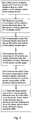
- FIG. 2 shows a schematic flow chart for an example of a method according to the present disclosure.
- the emissive display elements of a display device are powered to display a test pattern on the display screen of the display device.
- the power consumption of the emissive display elements is measured when the test pattern is being displayed on the display screen.
- the emissive display elements are subsequently powered to display the same test pattern on the display screen again.
- the power consumption of the emissive display elements is measured when the test pattern is being displayed on the display screen again.
- the initial value for power consumption of the emissive display elements and the subsequent value for power consumption of the emissive display elements are compared.
- At 210 it is determined that at least one of the emissive display elements is faulty if the initial value for power consumption of the emissive display elements and the subsequent value for power consumption of the emissive display elements differ. In such a case, corrective action to fix the emissive display element(s) may be implemented.
- processor or processing system or circuitry referred to herein may in practice be provided by a single chip or integrated circuit or plural chips or integrated circuits, optionally provided as a chipset, an application-specific integrated circuit (ASIC), field-programmable gate array (FPGA), digital signal processor (DSP), graphics processing units (GPUs), etc.
- the chip or chips may comprise circuitry (as well as possibly firmware) for embodying at least one or more of a data processor or processors, a digital signal processor or processors, baseband circuitry and radio frequency circuitry, which are configurable so as to operate in accordance with the exemplary embodiments.
- the exemplary embodiments may be implemented at least in part by computer software stored in (non-transitory) memory and executable by the processor, or by hardware, or by a combination of tangibly stored software and hardware (and tangibly stored firmware).
- Suitable devices include for example a hard disk and non-volatile semiconductor memory (including for example a solid-state drive or SSD).
- the invention also extends to computer programs, particularly computer programs on or in a carrier, adapted for putting the invention into practice.
- the program may be in the form of non-transitory source code, object code, a code intermediate source and object code such as in partially compiled form, or in any other non-transitory form suitable for use in the implementation of processes according to the invention.
- the carrier may be any entity or device capable of carrying the program.
- the carrier may comprise a storage medium, such as a solid-state drive (SSD) or other semiconductor-based RAM; a ROM, for example a CD ROM or a semiconductor ROM; a magnetic recording medium, for example a floppy disk or hard disk; optical memory devices in general; etc.
- SSD solid-state drive
- ROM read-only memory
- magnetic recording medium for example a floppy disk or hard disk
- optical memory devices in general etc.
Landscapes
- Engineering & Computer Science (AREA)
- Physics & Mathematics (AREA)
- Computer Hardware Design (AREA)
- General Physics & Mathematics (AREA)
- Theoretical Computer Science (AREA)
- Electroluminescent Light Sources (AREA)
- Control Of Indicators Other Than Cathode Ray Tubes (AREA)
Abstract
A display device (10) has a display screen (12) having emissive display elements (14). The emissive display elements (14) are initially powered to display a test pattern and the power consumption is measured to obtain an initial value for power consumption of the emissive display elements (14) when the test pattern is being displayed. The display elements (14) are subsequently powered to display the same test pattern and the power consumption is measured to obtain a subsequent value for power consumption of the emissive display elements (14) when the test pattern is being displayed. The initial value and the subsequent value for power consumption of the emissive display elements (14) are compared. It is determined that at least one of the emissive display elements (14) is faulty if the initial value and the subsequent value differ by more than a threshold.
Description
- The present disclosure relates to a display device and a method of operating a display device.
- It is known that some display devices are prone to image retention (or "image sticking" or "burn-in"). This causes the display device to continue to display an image, or parts of image, when the display device should be displaying a new image. Various techniques are known for attempting to prevent image retention occurring.
- In addition, various techniques are known for dealing with and attempting to fix image retention if it does occur. However, this requires that the image retention be detected in the first place. Typically, this is effectively a manual process and relies for example on a user visually noticing the image retention and manually initiating the fixing process.
- According to a first aspect disclosed herein, there is provided a method of operating a display device, the display device comprising a display screen having a plurality of emissive display elements, the method comprising:
- initially powering the emissive display elements to display a test pattern on the display screen;
- measuring the power consumption of the emissive display elements when the test pattern is being displayed on the display screen to obtain an initial value for power consumption of the emissive display elements when the test pattern is being displayed;
- subsequently powering the emissive display elements to display the same test pattern on the display screen again;
- measuring the power consumption of the emissive display elements when the test pattern is being displayed on the display screen again to obtain a subsequent value for power consumption of the emissive display elements when the test pattern is being displayed;
- comparing the initial value for power consumption of the emissive display elements and the subsequent value for power consumption of the emissive display elements; and
- determining that at least one of the emissive display elements is faulty if the initial value for power consumption of the emissive display elements and the subsequent value for power consumption of the emissive display elements differ by more than a threshold.
- The threshold may be a percentage difference in values, such as more than 0.1% or more than 0.2% or more than 0.5% or more than 1%, etc. Alternatively, the threshold may be an absolute value, such as a certain number of Watts.
- In an example, the method comprises initiating a process to fix image retention if it is determined that at least one of the emissive display elements is faulty and causing image retention.
- The determining that at least one of the emissive display elements is faulty may determine that at least one of the emissive display elements is causing image retention (or image "sticking"). This can occur because of so-called "burn-in" or ageing of one or more of the emissive display elements. Various methods for fixing image retention in emissive displays are known.
- In an example, the test pattern comprises at least one of a white image and a black image.
- The test pattern, such as a white image and/or a black image, may cover the whole display screen so as effectively to test all of the emissive display elements simultaneously.
- In an example, the initially powering the emissive display elements to display a test pattern on the display screen takes place when the display device is first powered up or first powered down.
- This first powering up/down may take place when the display device is first powered up/down as a final manufacturing step, by for example the manufacturer as a "one-off' step. The initial value for power consumption of the emissive display elements may be stored in permanent storage on the display device in such a case.
- Alternatively as another option, the first powering up/down may take place when the display device is first powered up/down by a user. This may be carried out for example as a "one-off' step when the display device is first used by the user.
- In an example, subsequently powering the emissive display elements to display the same test pattern on the display screen again takes place when the display device is subsequently powered up or subsequently powered down by a user.
- This subsequently powering up/down may take place every time the user powers up/down the display device, or every nth time the user powers up/down the display device where n is an integer greater than 1.
- In an example, the emissive display elements are powered to display a test pattern on the display screen with a refresh rate equal to or greater than 100 Hz. In an example, the emissive display elements are powered to display a test pattern on the display screen for one cycle of the refresh rate, such that the emissive display elements are powered for 0.01 seconds or less when displaying the test pattern.
- In an example, the emissive display elements are powered for 0.1 seconds or less when displaying the test pattern.
- In an example, the emissive display elements are organic light emitting diodes.
- According to a second aspect disclosed herein, there is provided a display device, the display device comprising:
- a display screen having a plurality of emissive display elements; and
- a processing system constructed and arranged to cause the display device to carry out a method comprising:
- initially powering the emissive display elements to display a test pattern on the display screen;
- measuring the power consumption of the emissive display elements when the test pattern is being displayed on the display screen to obtain an initial value for power consumption of the emissive display elements when the test pattern is being displayed;
- subsequently powering the emissive display elements to display the same test pattern on the display screen again;
- measuring the power consumption of the emissive display elements when the test pattern is being displayed on the display screen again to obtain a subsequent value for power consumption of the emissive display elements when the test pattern is being displayed;
- comparing the initial value for power consumption of the emissive display elements and the subsequent value for power consumption of the emissive display elements; and
- determining that at least one of the emissive display elements is faulty if the initial value for power consumption of the emissive display elements and the subsequent value for power consumption of the emissive display elements differ by more than a threshold.
- The processing system may comprise at least one processor and at least one memory including computer program instructions, the at least one memory and the computer program instructions being configured, with the at least one processor, to cause the display device at least to perform a method as described above.
- To assist understanding of the present disclosure and to show how embodiments may be put into effect, reference is made by way of example to the accompanying drawings in which:
-
Figure 1 shows schematically an example of a display device having emissive display elements according to the present disclosure; and -
Figure 2 shows a schematic flow chart for an example of a method according to the present disclosure. - As mentioned, it is known that some display devices are prone to image retention (or "image sticking" or "burn-in"). This causes the display device to continue to display an image, or parts of image, when the display device should be displaying a new image. This is a particular problem with display devices that use emissive display elements, including for example plasma displays and OLED (organic light emitting diode) displays which respectively use plasma cells and OLEDs as the emissive display elements. OLEDs display devices in particular are popular because they do not require a backlight, have low power consumption, enable deep blacks to be displayed, have a large field of view, and have fast response times and so are not so prone to motion blur.
- Image retention can occur because for example a static image has been displayed for a (relatively) long time by the display device. This is exacerbated if the image is a bright image. In addition, the display elements can effectively degrade over time. This can mean that the brightness output by the display element for a certain voltage is lowered every time the display element is driven to output light. This is a particular problem with OLEDs. Moreover, this degrading of the display element affects different colour display elements differently (where the "colour" of a display element is the colour of light that is output by the display element). Again, this is a particular problem with OLEDs. For example, some studies have shown that a red "sub-pixel" is the fastest to degrade, followed by blue sub-pixels and then green sub-pixels.
- Again as mentioned, various techniques are known for attempting to prevent image retention occurring. For example, some display devices detect the presence of a static image and effectively shift the image around the screen slightly so that different display elements are powered at different times whilst the same image is being displayed. Screen savers may also be used. However, this is not always successful, and cannot prevent degrading of for example OLEDs which occurs simply through use.
- Various techniques are known for dealing with and attempting to fix image retention if it does occur. However, this requires that the image retention be detected in the first place. Typically, this is effectively a manual process and relies for example on a user visually noticing the image retention and manually initiating the fixing process.
- Examples described herein enable faulty emissive display elements of a display device to be detected in an automated manner, which does not require any manual input by a user. In short, this is based on initially measuring power consumption by the display device and comparing power consumption at later times with the initial power consumption. If one or more faulty emissive display elements are detected, action can be initiated to address this. For example, a process to fix image retention can be initiated if it is determined that at least one of the emissive display elements is faulty and causing image retention. As mentioned, a number of techniques are known for dealing with and attempting to fix image retention if it does occur and one or more of these can be applied as necessary.
- Referring now to the drawings,
Figure 1 shows schematically an example of adisplay device 10 having emissive display elements according to an aspect described herein. Thedisplay device 10 of this example is a television set. Aspects described herein can also be applied to other display devices having emissive display elements, including for example computer displays or monitors, smartphones, tablet computers, laptop computers, etc., display devices used as so-called "signage", etc. - The
display device 10 has adisplay screen 12. Thedisplay screen 12 has a number ofemissive display elements 14, only some of which are shown inFigure 1 . In an example of particular interest, theemissive display elements 14 are OLEDs (organic light emitting diodes). In another example, theemissive display elements 14 are plasma cells as used in plasma displays. The number ofdisplay elements 14 depends principally on the resolution of thedisplay screen 12, that is the number of "pixels" of thedisplay screen 12. As is known, at each pixel, there may in fact be plural display elements, commonly referred to as "sub-pixels". For example, there may be a red, a green and a blue "sub-pixel" at each pixel, each of which is anemissive display element 14 which respectively outputs red, green and blue light. In some examples, there may be one or more additional sub-pixels at each pixel, such that each pixel has for example the combination of red, green, blue, and yellow (RGBY), or red, green, blue and white (RGBW), or red, green, blue, yellow and cyan (RGBYC). - The
display device 10 has amainboard 16 for controlling thedisplay device 10 and other functions. Themainboard 16 has theusual processor 18, workingmemory 20 anddata storage 22. Theprocessor 18 controls operation of thedisplay device 10 in accordance with software (one or more computer programs) stored in thedata storage 22 and executed by theprocessor 18 using the workingmemory 20. Whilst asingle processor 18 is shown for controlling the entire operation of thedisplay device 10, there may be plural processors for controlling different aspects of thedisplay device 10, and/or there may be additional circuity for controlling different aspects. There may also be a power board, which includes or is connected to a voltage transformer to provide supply voltages from an incoming mains power supply to one or more components of thedisplay device 10. However, such functionality may alternatively be provided by a one or more components on themainboard 16. In particular, there may be adisplay power component 24 which provides power to thedisplay elements 14 as required to generate an image on thedisplay screen 12. - In an example and in overview, the
display device 10 operates to detect the presence of one or morefaulty display elements 14 by displaying a test pattern on thedisplay screen 12 and measuring the power consumption of thedisplay elements 14. This is done initially, effectively to obtain an initial, reference value for the power consumption. This is then carried out later, during normal use of thedisplay device 10, to obtain one or more subsequent values for the power consumption. The initial and subsequent values for the power consumption are compared and if they differ (by more than a threshold), then it is determined that one or more of thedisplay elements 14 is faulty. This may be a determination that the one or more of thedisplay elements 14 is causing image retention. In such a case, in an example thedisplay device 10 can then initiate a process to fix the image retention. In an example, this can all be done automatically, requiring no manual user input. - In more detail, in an example the test pattern may be an all black image. In such a case, the
display elements 14 are not driven or powered at all or are only driven with a minimum drive current and voltage, so that thedisplay elements 14 emit no light or only a minimum amount of light. In such a case, the initial, reference value for the power consumption of thedisplay elements 14 will be a minimum. On the other hand, over time one or more of thedisplay elements 14 may develop a fault (which may simply be through ageing, as known to occur for OLEDs in particular). In such a case, when the black test pattern is displayed again, thedisplay device 10 cannot turn down the power consumption of the faulty display element(s) 14, such that the overall power consumption of thedisplay elements 14, and indeed of thedisplay device 10 as a whole, is different when the black test pattern is displayed again. In particular, the power consumption of thedisplay elements 14, and indeed of thedisplay device 10 as a whole, is now greater than when the test pattern was initially displayed and alldisplay elements 14 were working correctly. That is: - power consumption when displaying black test pattern with image sticking >
- power consumption when displaying black test pattern with no image sticking
- In another example the test pattern may be an all white image. In such a case, the
display elements 14 are driven with a maximum power so that thedisplay elements 14 emit a maximum amount of light. In the case that thedisplay elements 14 are sub-pixels, then, being white light, this means that all sub-pixels are driven with a maximum power. In any event, in such a case, the initial, reference value for the power consumption of thedisplay elements 14 will be a maximum. On the other hand, over time one or more of thedisplay elements 14 may develop a fault (which, again, may simply be through ageing, as known to occur for OLEDs in particular). In such a case, when the white test pattern is displayed again, the overall power consumption of thedisplay elements 14, and indeed of thedisplay device 10 as a whole, is different. In particular, the power consumption of thedisplay elements 14, and indeed of thedisplay device 10 as a whole, is now less than when the test pattern was initially displayed and alldisplay elements 14 were working correctly. That is: - power consumption when displaying white test pattern with image sticking <
- power consumption when displaying white test pattern with no image sticking
- The
display device 10 may use only a black test pattern or only a white test pattern. Thedisplay device 10 may use a black test pattern and a white test pattern. Thedisplay device 10 may for example alternate the use of the black and white test patterns, or use a black test pattern a predetermined number of times followed by using a white test pattern a predetermined number of times, or use other variations. - As mentioned, it is determined that one or more of the
display elements 14 is faulty if the initial and subsequent values for the power consumption differ. A threshold difference may be applied for this such that it is only determined that one or more of thedisplay elements 14 is faulty if the initial and subsequent values for the power consumption differ by more than a threshold. The threshold may be a percentage difference in values, such as a difference of more than 0.1% or more than 0.2% or more than 0.5% or more than 1%, etc. Alternatively, the threshold may be an absolute value, such as a difference of a certain number of Watts. It is straightforward to determine appropriate values for the percentage difference or absolute difference by appropriate testing of thedisplay device 10. The appropriate threshold will in general be different fordifferent display devices 10 which may use different technology or different materials, etc. for thedisplay elements 14. - When displaying the test pattern, the test pattern may be displayed with a refresh rate that is fast enough and/or displayed for a short enough time that the user or other viewer is unlikely to notice that a test pattern is actually being displayed. For example, the
display elements 14 may be powered to display a test pattern on the display screen with a refresh rate greater than 100 Hz or so. In an example, the test pattern may be displayed for a fixed (short) time, such as less than 0.5 seconds, less than 0.1 seconds, less than 0.01 seconds, or only for 1 or 2 milliseconds say. In other examples, the test pattern may be displayed for only one cycle of the refresh rate, so that the test pattern is displayed for only 1/100th of a second in the case of a refresh rate of 100 Hz and correspondingly if other refresh rates are used. - It is mentioned that the
display device 10 operates to detect the presence of one or morefaulty display elements 14 by initially displaying a test pattern on thedisplay screen 12 and measuring the power consumption of thedisplay elements 14 for this initial test display. A number of options for this are possible. - For example, the
display elements 14 may be driven or powered to display the test pattern when the display device is first powered up or first powered down as a final manufacturing step, by for example the manufacturer of thedisplay device 10 as a "one-off' step. The initial value for power consumption of thedisplay elements 14 may be stored inpermanent storage 22 of thedisplay device 10 in such a case. These initial values therefore provide a "permanent" reference for comparison with the power consumption that occurs when the (same) test pattern is displayed later. - As another example, the
display elements 14 may be driven or powered to display the test pattern when thedisplay device 10 is first powered up or first powered down by a user, for example when the user has purchased thedisplay device 10 and is using it for the first time. Software operating on thedisplay device 10 may then cause the measured power consumption to be stored inpermanent storage 22 of thedisplay device 10 in such a case. This may therefore be carried out for example as a "one-off' step when the display device is first used by the user. These initial values provide a "permanent" reference for comparison with the power consumption that occurs when the (same) test pattern is displayed later. - Similarly, it is mentioned that the
display device 10 operates to detect the presence of one or morefaulty display elements 14 by subsequently displaying a test pattern on thedisplay screen 12 and measuring the power consumption of thedisplay elements 14 for this subsequent test display. A number of options for this are possible. - For example, the
display elements 14 may be driven to display the test pattern every time that thedisplay device 10 is powered up (or powered down) by a user. As another example, thedisplay elements 14 may be driven to display the test pattern every nth time that thedisplay device 10 is powered up (or powered down) by a user, where n is an integer greater than one (such as 3 or 5 or 10, etc.). - In this respect, "powering up" of the
display device 10 may include switching on thedisplay device 10 after thedisplay device 10 has been switched (completely) off, or waking thedisplay device 10 from a sleep mode. Similarly, "powering down" of thedisplay device 10 may include switching the display device 10 (completely) off, or putting thedisplay device 10 in sleep mode. In such a case, thedisplay device 10 causes the test pattern to be displayed again and the power consumption to be measured and compared with the initial value before actually switching off thedisplay device 10 or putting thedisplay device 10 into sleep mode, as the case may be. - In any of the examples, the power consumption that is measured is preferably the power consumption of (only) the
display elements 14. This may be achieved by measuring the power output by the mainboard 16 (or power board if present) to thedisplay elements 14 when the test pattern(s) is (are) being displayed. This may be the power that is output or controlled to be output by thedisplay power component 24 in the example above. Alternatively, the power consumption that is measured may be the power consumption of thedisplay device 10 as a whole. In such a case, it is preferred that the state of thedisplay device 10 be in substance the same for each measurement (such that, for example, volume levels of any audio output are the same) to avoid other differences of power consumption interfering with the measurements. - It may be noted that the power consumption of an
individual display element 14, such as an OLED, is quite low. Nevertheless, in practice, it is likely that a large number of thedisplay elements 14 become faulty. As such, the variation in overall power consumption can be quite large when image sticking occurs in practice. For example, even though the power consumption of for example an OLED may be of the order of milliwatts or less, thousands or tens or even hundreds of thousands of the OLEDs in thedisplay screen 12 may be faulty, such that the power variation may be of the order of up to a Watt or so. (AnOLED display screen 12 having a resolution of 3840 x 2160 pixels, i.e. a total of 8,294,400 pixels, may have (at least) 24,883,200 OLEDs as there are (at least) 3 OLEDs or sub-pixels for each pixel, being one red, one green and one blue. If 1 % of the OLEDs are faulty, which will be easily noticeable to a viewer, that means that 248,832 OLEDs are faulty, leading to a power variation that is easily measurable.) - If one or more faulty
emissive display elements 14 are detected and are causing image retention, then a process to fix the image retention can be initiated. A number of techniques are known for dealing with and attempting to fix image retention if it does occur and one or more of these can be applied as necessary. For example, it is known to perform pixel "refreshing" in which a (typically bright white) line is caused to traverse the screen horizontally or vertically, typically for a period of an hour or more, in essence to even the ageing of the display elements. - Referring now to
Figure 2 , this shows a schematic flow chart for an example of a method according to the present disclosure. - At 200, the emissive display elements of a display device are powered to display a test pattern on the display screen of the display device.
- At 202, the power consumption of the emissive display elements is measured when the test pattern is being displayed on the display screen.
- At 204, the emissive display elements are subsequently powered to display the same test pattern on the display screen again.
- At 206, the power consumption of the emissive display elements is measured when the test pattern is being displayed on the display screen again.
- At 208, the initial value for power consumption of the emissive display elements and the subsequent value for power consumption of the emissive display elements are compared.
- At 210, it is determined that at least one of the emissive display elements is faulty if the initial value for power consumption of the emissive display elements and the subsequent value for power consumption of the emissive display elements differ. In such a case, corrective action to fix the emissive display element(s) may be implemented.
- It will be understood that the processor or processing system or circuitry referred to herein may in practice be provided by a single chip or integrated circuit or plural chips or integrated circuits, optionally provided as a chipset, an application-specific integrated circuit (ASIC), field-programmable gate array (FPGA), digital signal processor (DSP), graphics processing units (GPUs), etc. The chip or chips may comprise circuitry (as well as possibly firmware) for embodying at least one or more of a data processor or processors, a digital signal processor or processors, baseband circuitry and radio frequency circuitry, which are configurable so as to operate in accordance with the exemplary embodiments. In this regard, the exemplary embodiments may be implemented at least in part by computer software stored in (non-transitory) memory and executable by the processor, or by hardware, or by a combination of tangibly stored software and hardware (and tangibly stored firmware).
- Reference is made herein to data storage for storing data. This may be provided by a single device or by plural devices. Suitable devices include for example a hard disk and non-volatile semiconductor memory (including for example a solid-state drive or SSD).
- Although at least some aspects of the embodiments described herein with reference to the drawings comprise computer processes performed in processing systems or processors, the invention also extends to computer programs, particularly computer programs on or in a carrier, adapted for putting the invention into practice. The program may be in the form of non-transitory source code, object code, a code intermediate source and object code such as in partially compiled form, or in any other non-transitory form suitable for use in the implementation of processes according to the invention. The carrier may be any entity or device capable of carrying the program. For example, the carrier may comprise a storage medium, such as a solid-state drive (SSD) or other semiconductor-based RAM; a ROM, for example a CD ROM or a semiconductor ROM; a magnetic recording medium, for example a floppy disk or hard disk; optical memory devices in general; etc.
- The examples described herein are to be understood as illustrative examples of embodiments of the invention. Further embodiments and examples are envisaged. Any feature described in relation to any one example or embodiment may be used alone or in combination with other features. In addition, any feature described in relation to any one example or embodiment may also be used in combination with one or more features of any other of the examples or embodiments, or any combination of any other of the examples or embodiments. Furthermore, equivalents and modifications not described herein may also be employed within the scope of the invention, which is defined in the claims.
Claims (15)
- A method of operating a display device, the display device comprising a display screen having a plurality of emissive display elements, the method comprising:initially powering the emissive display elements to display a test pattern on the display screen;measuring the power consumption of the emissive display elements when the test pattern is being displayed on the display screen to obtain an initial value for power consumption of the emissive display elements when the test pattern is being displayed;subsequently powering the emissive display elements to display the same test pattern on the display screen again;measuring the power consumption of the emissive display elements when the test pattern is being displayed on the display screen again to obtain a subsequent value for power consumption of the emissive display elements when the test pattern is being displayed;comparing the initial value for power consumption of the emissive display elements and the subsequent value for power consumption of the emissive display elements; anddetermining that at least one of the emissive display elements is faulty if the initial value for power consumption of the emissive display elements and the subsequent value for power consumption of the emissive display elements differ by more than a threshold.
- A method according to claim 1, comprising initiating a process to fix image retention if it is determined that at least one of the emissive display elements is faulty and causing image retention.
- A method according to claim 1 or claim 2, wherein the test pattern comprises at least one of a white image and a black image.
- A method according to any of claims 1 to 3, wherein the initially powering the emissive display elements to display a test pattern on the display screen takes place when the display device is first powered up or first powered down.
- A method according to any of claims 1 to 4, wherein subsequently powering the emissive display elements to display the same test pattern on the display screen again takes place when the display device is subsequently powered up or subsequently powered down by a user.
- A method according to any of claims 1 to 5, wherein the emissive display elements are powered to display a test pattern on the display screen with a refresh rate equal to or greater than 100 Hz.
- A method according to claim 6, wherein the emissive display elements are powered to display a test pattern on the display screen for one cycle of the refresh rate, such that the emissive display elements are powered for 0.01 seconds or less when displaying the test pattern.
- A method according to any of claims 1 to 7, wherein the emissive display elements are powered for 0.1 seconds or less when displaying the test pattern.
- A method according to any of claims 1 to 8, wherein the emissive display elements are organic light emitting diodes.
- A display device, the display device comprising:a display screen having a plurality of emissive display elements; anda processing system constructed and arranged to cause the display device to carry out a method comprising:initially powering the emissive display elements to display a test pattern on the display screen;measuring the power consumption of the emissive display elements when the test pattern is being displayed on the display screen to obtain an initial value for power consumption of the emissive display elements when the test pattern is being displayed;subsequently powering the emissive display elements to display the same test pattern on the display screen again;measuring the power consumption of the emissive display elements when the test pattern is being displayed on the display screen again to obtain a subsequent value for power consumption of the emissive display elements when the test pattern is being displayed;comparing the initial value for power consumption of the emissive display elements and the subsequent value for power consumption of the emissive display elements; anddetermining that at least one of the emissive display elements is faulty if the initial value for power consumption of the emissive display elements and the subsequent value for power consumption of the emissive display elements differ by more than a threshold.
- A display device according to claim 10, wherein the method comprises initiating a process to fix image retention if it is determined that at least one of the emissive display elements is faulty and causing image retention.
- A display device according to claim 10 or claim 11, wherein the test pattern comprises at least one of a white image and a black image.
- A display device according to any of claims 10 to 12, wherein the emissive display elements are powered to display a test pattern on the display screen with a refresh rate greater than 100 Hz.
- A display device according to claim 13, wherein the emissive display elements are powered to display a test pattern on the display screen for one cycle of the refresh rate, such that the emissive display elements are powered for less than 0.6 seconds when displaying the test pattern.
- A display device according to any of claims 10 to 14, wherein the emissive display elements are organic light emitting diodes.
Priority Applications (1)
| Application Number | Priority Date | Filing Date | Title |
|---|---|---|---|
| EP19194413.1A EP3786938A1 (en) | 2019-08-29 | 2019-08-29 | Display device and a method of operation |
Applications Claiming Priority (1)
| Application Number | Priority Date | Filing Date | Title |
|---|---|---|---|
| EP19194413.1A EP3786938A1 (en) | 2019-08-29 | 2019-08-29 | Display device and a method of operation |
Publications (1)
| Publication Number | Publication Date |
|---|---|
| EP3786938A1 true EP3786938A1 (en) | 2021-03-03 |
Family
ID=67809356
Family Applications (1)
| Application Number | Title | Priority Date | Filing Date |
|---|---|---|---|
| EP19194413.1A Withdrawn EP3786938A1 (en) | 2019-08-29 | 2019-08-29 | Display device and a method of operation |
Country Status (1)
| Country | Link |
|---|---|
| EP (1) | EP3786938A1 (en) |
Citations (3)
| Publication number | Priority date | Publication date | Assignee | Title |
|---|---|---|---|---|
| US20140055500A1 (en) * | 2012-08-23 | 2014-02-27 | Research In Motion Limited | Organic light emitting diode based display aging monitoring |
| US20170124929A1 (en) * | 2015-11-03 | 2017-05-04 | Medtronic Minimed, Inc. | Detecting breakage in a display element |
| US20180151119A1 (en) * | 2016-11-25 | 2018-05-31 | Lg Display Co., Ltd. | Organic Light Emitting Display Device and Method for Driving the Same |
-
2019
- 2019-08-29 EP EP19194413.1A patent/EP3786938A1/en not_active Withdrawn
Patent Citations (3)
| Publication number | Priority date | Publication date | Assignee | Title |
|---|---|---|---|---|
| US20140055500A1 (en) * | 2012-08-23 | 2014-02-27 | Research In Motion Limited | Organic light emitting diode based display aging monitoring |
| US20170124929A1 (en) * | 2015-11-03 | 2017-05-04 | Medtronic Minimed, Inc. | Detecting breakage in a display element |
| US20180151119A1 (en) * | 2016-11-25 | 2018-05-31 | Lg Display Co., Ltd. | Organic Light Emitting Display Device and Method for Driving the Same |
Similar Documents
| Publication | Publication Date | Title |
|---|---|---|
| US10971060B2 (en) | Method of adjusting display brightness, light-emission control circuit and display device | |
| US10431148B2 (en) | Module type display apparatus, display apparatus comprising the module type display apparatus, and control method thereof | |
| CN102203845B (en) | Display device and driving method thereof | |
| US9740046B2 (en) | Method and apparatus to provide a lower power user interface on an LCD panel through localized backlight control | |
| JP5321033B2 (en) | Display device and driving method of display device | |
| US10013922B2 (en) | Control device and control device controlling method | |
| US10163388B2 (en) | Light-emitting diode displays with predictive luminance compensation | |
| CN108109585B (en) | Organic light-emitting display device and method of driving the same | |
| US10997914B1 (en) | Systems and methods for compensating pixel voltages | |
| CN114613302B (en) | Life aging method for display device and display device | |
| US20230186837A1 (en) | Display device and control method therefor | |
| KR20180068639A (en) | Display apparatus and seam correction method thereof | |
| KR20190043661A (en) | Organic light emitting display device and method for setting gamma reference voltage thereof | |
| US20120268501A1 (en) | Display device | |
| US12136387B2 (en) | Frame insertion and frame rate sequencing for panel glitch prevention | |
| US9406282B2 (en) | Display protection for invalid timing signals | |
| CN111816129A (en) | Display control parameter determination method, device and computer-readable storage medium | |
| US20200312228A1 (en) | Display apparatus and controlling method thereof | |
| US20130278581A1 (en) | Devices and methods for pixel discharge before display turn-off | |
| CN110710195A (en) | Image display apparatus and control method thereof | |
| CN101685040B (en) | Display test device and test method | |
| KR102037069B1 (en) | Apparatus for inspecting display panel and method thereof | |
| CN111816106B (en) | Display control method, device and computer-readable storage medium | |
| JP5990740B2 (en) | Display device, video type determination device, display device driving method, and video type determination method | |
| JP2013101237A (en) | Display control device and electronic apparatus using the same |
Legal Events
| Date | Code | Title | Description |
|---|---|---|---|
| PUAI | Public reference made under article 153(3) epc to a published international application that has entered the european phase |
Free format text: ORIGINAL CODE: 0009012 |
|
| STAA | Information on the status of an ep patent application or granted ep patent |
Free format text: STATUS: THE APPLICATION HAS BEEN PUBLISHED |
|
| AK | Designated contracting states |
Kind code of ref document: A1 Designated state(s): AL AT BE BG CH CY CZ DE DK EE ES FI FR GB GR HR HU IE IS IT LI LT LU LV MC MK MT NL NO PL PT RO RS SE SI SK SM TR |
|
| AX | Request for extension of the european patent |
Extension state: BA ME |
|
| STAA | Information on the status of an ep patent application or granted ep patent |
Free format text: STATUS: THE APPLICATION HAS BEEN WITHDRAWN |
|
| 18W | Application withdrawn |
Effective date: 20210824 |