EP3786895A1 - Method, device and apparatus for repositioning in camera orientation tracking process, and storage medium - Google Patents
Method, device and apparatus for repositioning in camera orientation tracking process, and storage medium Download PDFInfo
- Publication number
- EP3786895A1 EP3786895A1 EP19794077.8A EP19794077A EP3786895A1 EP 3786895 A1 EP3786895 A1 EP 3786895A1 EP 19794077 A EP19794077 A EP 19794077A EP 3786895 A1 EP3786895 A1 EP 3786895A1
- Authority
- EP
- European Patent Office
- Prior art keywords
- image
- end program
- relocalization
- target image
- pose parameter
- Prior art date
- Legal status (The legal status is an assumption and is not a legal conclusion. Google has not performed a legal analysis and makes no representation as to the accuracy of the status listed.)
- Granted
Links
Images




Classifications
-
- G—PHYSICS
- G06—COMPUTING OR CALCULATING; COUNTING
- G06T—IMAGE DATA PROCESSING OR GENERATION, IN GENERAL
- G06T7/00—Image analysis
- G06T7/70—Determining position or orientation of objects or cameras
- G06T7/73—Determining position or orientation of objects or cameras using feature-based methods
- G06T7/74—Determining position or orientation of objects or cameras using feature-based methods involving reference images or patches
-
- G—PHYSICS
- G06—COMPUTING OR CALCULATING; COUNTING
- G06T—IMAGE DATA PROCESSING OR GENERATION, IN GENERAL
- G06T7/00—Image analysis
- G06T7/20—Analysis of motion
- G06T7/246—Analysis of motion using feature-based methods, e.g. the tracking of corners or segments
- G06T7/248—Analysis of motion using feature-based methods, e.g. the tracking of corners or segments involving reference images or patches
-
- G—PHYSICS
- G06—COMPUTING OR CALCULATING; COUNTING
- G06T—IMAGE DATA PROCESSING OR GENERATION, IN GENERAL
- G06T7/00—Image analysis
- G06T7/20—Analysis of motion
- G06T7/269—Analysis of motion using gradient-based methods
-
- G—PHYSICS
- G06—COMPUTING OR CALCULATING; COUNTING
- G06T—IMAGE DATA PROCESSING OR GENERATION, IN GENERAL
- G06T2207/00—Indexing scheme for image analysis or image enhancement
- G06T2207/10—Image acquisition modality
- G06T2207/10016—Video; Image sequence
-
- G—PHYSICS
- G06—COMPUTING OR CALCULATING; COUNTING
- G06T—IMAGE DATA PROCESSING OR GENERATION, IN GENERAL
- G06T2207/00—Indexing scheme for image analysis or image enhancement
- G06T2207/30—Subject of image; Context of image processing
- G06T2207/30204—Marker
-
- G—PHYSICS
- G06—COMPUTING OR CALCULATING; COUNTING
- G06T—IMAGE DATA PROCESSING OR GENERATION, IN GENERAL
- G06T2207/00—Indexing scheme for image analysis or image enhancement
- G06T2207/30—Subject of image; Context of image processing
- G06T2207/30244—Camera pose
Definitions
- Embodiments of this application relate to the field of augmented reality (AR), and in particular, to a relocalization method and apparatus in a camera pose tracking process, a device, and a storage medium.
- AR augmented reality
- a subject equipped with a camera needs to track a movement pose of the camera in the real environment during movement without a priori information of the environment.
- a previous image of the current image is switched to an (i+1) th anchor image, and an (i+1) th tracking process is started, i being a positive integer.
- Embodiments of this application provide a relocalization method and apparatus in a camera pose tracking process, a device, and a storage medium, to resolve a problem that a relocalization process consumes a relatively long time, and as a result a main thread may be blocked and a relocalization result may be obtained only after several frames of image.
- the technical solutions are as follows:
- a relocalization method in a camera pose tracking process applied to a device on which a front-end program and a back-end program are run, the front-end program being used to sequentially perform a camera pose tracking process on a plurality of anchor images, the method including:
- a relocalization apparatus in a camera pose tracking process including a front-end program module and a back-end program module, the front-end program module being configured to sequentially perform a camera pose tracking process on a plurality of anchor images; the front-end program module being further configured to obtain a target image acquired after an i th anchor image in the plurality of anchor images, i being a positive integer; the front-end program module being further configured to: switch the target image to an (i+1) th anchor image in a case that the target image satisfies a relocalization condition, and transmit the target image to the back-end program module; the front-end program module being further configured to: obtain a current image acquired after the target image, and perform feature point tracking on the current image relative to the target image to obtain a first pose parameter, the first pose parameter being used to represent a change amount of a camera pose from the target image to the current image; the back-end program module being configured to: perform relocalization
- a front-end program switches a target image to an (i+1) th anchor image.
- the front-end program performs camera pose tracking based on the (i+1) th anchor image in parallel to obtain a first pose parameter.
- the first pose parameter and the second pose parameter are used to correct a positioning result of a current image in a case that a relocalization result (a second pose parameter) is obtained during processing of the current image by the front-end program, thereby resolving a problem that the back-end program cannot control the time of obtaining a successful relocalization result, and a relocalization result obtained several frames of image before cannot be directly used for relocalization of the current image.
- Even if it takes a relatively long time for the back-end program to obtain a relocalization result two pose change amounts can be added to correct the positioning result of the current image, thereby ensuring a relatively adequate relocalization effect.
- AR is a technology that as a camera acquires an image, a camera pose parameter of the camera in the real world (or referred to as the three-dimensional world or the actual world) is calculated in real time, and a virtual element is added according to the camera pose parameter to the image acquired by the camera.
- the virtual element includes, but is not limited to, an image, a video, and a three-dimensional model.
- the objective of the AR technology is to overlay the virtual world on a screen onto the real world to perform interaction.
- the camera pose parameter includes a rotation matrix and a displacement vector.
- the rotation matrix is used to represent a rotation angle of the camera in the real world.
- the displacement vector is used to represent a displacement distance of the camera in the real world.
- a device adds a figure of a virtual human to an image photographed by a camera.
- the image photographed by the camera changes, and a photographing position of the virtual human also changes, thereby simulating an effect that the virtual human is still in the image and the camera photographs the image and the virtual human while the position and pose are changing, so as to present a realistic three-dimensional picture to a user.
- An anchor-switching AR system is an AR system that determines a camera pose parameter in a natural scene based on camera pose tracking of a plurality of consecutive anchor images and overlays the virtual world according to the camera pose parameter onto an image acquired by a camera.
- An inertial measurement unit is an apparatus configured to measure tri-axial attitude angles (or angular velocities) and accelerations of an object.
- the IMU includes three uniaxial accelerometers and three uniaxial gyroscopes.
- the accelerometer is configured to detect an acceleration signal of an object on each coordinate axis of a three-dimensional coordinate system, to calculate the displacement vector (errors may accumulate as time elapses).
- the gyroscopes are configured to detect a rotation matrix of the object in the three-dimensional coordinate system.
- the IMU includes a gyroscope, an accelerometer, and a geomagnetic sensor.
- a manner of establishing a three-dimensional coordinate system is as follows: 1.
- the X axis is defined by a vector product Y ⁇ Z, and a direction tangential to the ground at a current position of the device on the X axis points to the east. 2.
- a direction tangential to the ground at the current position of the device on the Y axis points to the north pole of the geomagnetic field.
- the Z axis points to the sky and is perpendicular to the ground.
- the processor 420 includes one or more processing cores, for example, a 4-core processor, an 8-core processor, and the like.
- the processor 420 is configured to execute at least one of an instruction, a code, a code segment, and a program stored in the memory 440.
- Normal tracking process ( FIG. 7 ): In a camera pose tracking process based on an i th anchor image, it is set that the i th anchor image has a pose change amount including R _i_old and T _i_old relative to the first anchor image.
- the back-end program performs relocalization on the target image relative to the first anchor image, to obtain the second pose parameter.
- the foregoing step 605 includes the following sub-steps:
- Step 605b Perform feature point tracking on the target image relative to the first anchor image, to obtain a target feature point matching the initial feature point.
- each matching feature point pair includes one initial feature point and one target feature point that match each other.
- a tracking algorithm based on visual odometry may be used for feature point tracking. This is not limited in this application.
- a Kanade-Lucas (KLT) optical flow tracking algorithm is used for feature point tracking.
- a SIFT feature descriptor extracted based on a scale-invariant feature transform (SIFT) algorithm and an ORB feature descriptor extracted based on an oriented FAST and rotated BRIEF (ORB, fast feature point extraction and description) algorithm are used to perform feature point tracking.
- SIFT scale-invariant feature transform
- ORB fast feature point extraction and description
- a specific algorithm for feature point tracking is not limited, and a feature point method or a direct method may be used for a feature point tracking process.
- the device calculates a homography matrix between two frames of image according to the initial feature point and the target feature point; and decomposes the homography matrix to obtain a pose change amount including R relocalize and T relocalize of the change of the camera from the initial pose parameter to the target pose parameter.
- relocalization is performed on a target image relative to the first anchor image.
- relocalization may fail in some scenarios. For example, in a case that a photographing pose corresponding to the target image is greatly different from a photographing pose of the first anchor image, relocalization implemented by directly establishing a match between the target image and the first anchor image may fail.
- the picture (1) in FIG. 10 is the first anchor image
- the picture (2) in FIG. 10 is the target image. Because there is an excessively small overlapping area between the target image and the first anchor image, and a sufficient matching degree is not reached, relocalization directly performed on the target image and the first anchor image fails.
- the picture (3) in FIG. 10 is introduced as a first-order keyframe, and relocalization is performed on the target image relative to a first-order keyframe, so that the success probability of relocalization can be improved.
- the back-end program chooses a target keyframe from the keyframe database.
- the target keyframe is an image at the smallest image distance from the target image in the keyframe database.
- the image distance can be represented by any form of an image similarity, an image feature similarity, and a distance between matching feature points. This is not limited in this embodiment of this application.
- the device chooses a target keyframe from the keyframe database by using a similarity between the first global descriptor of the keyframe and the second global descriptor of the target image.
- the device chooses a target keyframe from the keyframe database by using the similarity between the first pose parameter of the keyframe and the reference pose parameter of the target image.
- Step 6052 Perform relocalization on the target image relative to the target keyframe, to obtain a second relocalization result.
- a process of relocalization includes the following steps:
- the device calculates a homography matrix between two frames of image according to the keyframe feature point and the target feature point; and decomposes the homography matrix to obtain the pose change amount including R cm and T cm of the change of the camera from the keyframe pose parameter to the second pose parameter, and use the pose change amount including R cm and T cm as the second relocalization result.
- Step 6053 Calculate a second pose parameter of the camera during acquisition of the target image according to the first relocalization result and the second relocalization result.
- the keyframe database includes: a first-order keyframe with successful first-order relocalization relative to the first anchor image, and/or, and an nth-order keyframe with successful nth order relocalization relative to the (n-1) th -order keyframe in the keyframe database, n being an integer greater than 1.
- a projected feature point obtained after the front-end program maps an initial feature point in the first anchor image onto the target image, and a process of calculating a scale corresponding to the target image according to an average depth of the projected feature point is as follows:
- a result module is provided between the front-end program and the back-end program between.
- the result module is a storage space shared by the front-end program and the back-end program.
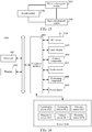
- the result module includes a relocalization list, a result-flag, and a result storage location.
- the result module further includes an expand-map list, an abandon time.
- the relocalization list is used to store a target image that requires relocalization.
- the target image is written into the relocalization list.
- the result storage location is used to store the second pose parameter including R relocalize and T relocalice in a case that relocalization succeeds.
- the expand-map list is used to store a candidate image of a keyframe database.
- the front-end program imports an image into the expand-map list during a normal camera tracking process for the back-end program to expand the keyframe database.
- the abandon time is used to store the time at which the front-end program switches an anchor image the last time. For example, in a case that the front-end program sets the target image as the (i+1) th anchor image, the front-end program records the switching time of the (i+1) th anchor image to the abandon time.
- the back-end program monitors the relocalization list and the expand-map list in the result module.
- Step 1201 Determine whether the relocalization list is empty.
- step 1202 it is determined that the front-end program does not have a target image that requires relocalization, and step 1202 is performed.
- step 1204 it is determined that the front-end program has a target image that requires relocalization, and step 1204 is performed.
- Step 1202 Determine whether the expand-map list is empty.
- Step 1203 is performed in a case that the expand-map list is not empty.
- Step 1200 is performed again in a case that the expand-map list is empty.
- Step 1203 Expand a keyframe database.
- the back-end program uses the candidate image in the expand-map list to expand keyframes in the keyframe database, so that keyframes in the keyframe database are added or updated.
- Step 1204 Set the result-flag to still-running.
- Step 1205 Perform relocalization on a target image that requires relocalization.
- Step 1206 Determine whether the relocalization process succeeds.
- Step 1207 is performed in a case that relocalization succeeds.
- Step 1208 is performed in a case that relocalization fails.
- the back-end program sets the result-flag to fail.
- Step 1209 Set the result-flag to success.
- Step 1301 Determine whether there is a tracking result.
- the front-end program obtains a target image acquired after the i th anchor image and after feature point tracking is performed on a target image relative to the i th anchor image, and determines whether there is a tracking result.
- Step 1302 is performed in a case that there is a tracking result.
- Step 1303 is performed in a case that there is no tracking result.
- Step 1302 Set flag1 to false.
- the camera pose tracking process in step 1300 continues to be performed.
- Step 1303 Set flag1 to true.
- the front-end program sets flagl to true, representing that relocalization needs to be performed on the target image.
- Step 1304 Detect the status of flag1.
- the front-end program During processing of each frame of image, the front-end program further detects the status of flag1.
- Step 1305 is performed in a case that the status of flag1 is false.
- the front-end program transmits the target image to the expand-map list for use by the back-end program to expand the keyframe database.
- Step 1306 is performed in a case that the status of flag1 is true.
- the front-end program considers that the target image being processed requires relocalization and detects the state of flag2.
- Step 1307 is performed in a case that the status of flag2 is false, representing that the last relocalization succeeds.
- Step 1313 is performed in a case that the status of flag2 is true, representing that the last relocalization fails.
- the front-end program reads the result-flag in the result module.
- the result-flag is ready, it indicates that the back-end program is in an idle state, and relocalization may be performed on the target image.
- Step 1308 Switch to an (i+1) th anchor image, transmit the abandon time, and transmit the target image to the relocalization list.
- the front-end program switches the target image to the (i+1) th anchor image, and writes the switching time into the abandon time in the result module.
- the front-end program reads the result-flag in the result module.
- Step 1310 is performed in a case that the result-flag is still-running.
- Step 1311 is performed in a case that the result-flag is have-result_ok.
- Step 1312 is performed in a case that the result-flag is have-result_fails.
- Step 1310 Conduct another transaction.
- the front-end program may perform a feature point tracking process on a current image after a target image in a calculation process in which the back-end program performs relocalization on the target image.
- Step 1311 Set flag 1 to fail.
- flagl is set to fail in a case that relocalization of the target image succeeds, representing that relocalization is not required, and a camera tracking process based on the (i+1) th anchor image is performed.
- flag2 is set to success in a case that relocalization of the target image fails.
- Step 1313 Switch to an (i+2) th anchor image, and transmit the abandon time.
- the front-end program obtains a current image after a target image
- flag1 is true and flag2 is true
- a relocalization process of the target image fails.
- the front-end program needs to transmit the current image after the target image to the relocalization list, so that the back-end program initiates a relocalization process on the current image.
- the front-end program switches the current image to an (i+2) th anchor image, and write the switching time into the abandon time in the result module again.
- the back-end program uses the candidate image in the expand-map list to expand a keyframe in a keyframe database, including the following steps: Step 1: Obtain a latest candidate image with successful relocalization.
- the keyframe database may be empty, and the back-end program only uses the first anchor image as an anchor image for relocalization.
- the back-end program only uses the first anchor image as an anchor image for relocalization.
- the back-end program uses the image with successful relocalization as a candidate image that may be added to the keyframe database.
- the successful relocalization includes: successful relocalization relative to the first anchor image, or, successful relocalization relative to an existing keyframe in the keyframe database.
- Step 2 Determine whether the candidate image satisfies an addition condition, the addition condition including: a first distance between the candidate image and the first anchor image is greater than a first threshold, and/or, a second distance between the candidate image and a keyframe added last time is greater than a second threshold.
- the back-end program calculates the first distance between the candidate image and the first anchor image.
- the first distance is used to represent an image similarity or a camera pose similarity between the candidate image and the first anchor image.
- a specific calculation manner of the first distance is not limited.
- for an initial feature point in the first anchor image a target feature point matching the initial feature point exists in the candidate image.
- One initial feature point and a corresponding target feature point constitute a matching feature point pair.
- An L2 distance (a Euclidean distance corresponding to the norm of L2) is calculated according to each matching feature point pair.
- An average value of all L2 distances is used as the first distance between the candidate image and the first anchor image.
- the first threshold is 50 pixels. In a case that the first distance between the candidate image and the first anchor image is greater than 50 pixels, the candidate image is added to the keyframe database.
- the back-end program calculates the second distance between the candidate image and the keyframe added last time.
- the second distance is used to represent an image similarity or a camera pose similarity between the candidate image and the keyframe added last time.
- a specific calculation manner of the second distance is not limited.
- a quantity of relocalization images between the candidate image and the keyframe added last time is used as the second distance.
- the second threshold is 10. In a case that the quantity of relocalization images between the candidate image and the keyframe added last time exceeds 10, the candidate image is added to the keyframe database.
- Step 3 Add the candidate image to the keyframe database in a case that the candidate image satisfies the addition condition.
- the candidate image is added to the keyframe database as a keyframe.
- a first global descriptor of the keyframe, a keyframe feature point, a positioning result of the first relocalization are stored in the keyframe database.
- the first global descriptor is used to represent the image of the keyframe feature by using a small data amount, and the positioning result of the first relocalization may be represented by a keyframe pose parameter of the camera during acquisition of a keyframe or may be represented by the pose change amount of the change of the camera from the initial pose parameter to the keyframe pose parameter.
- Step 4 Skip adding the candidate image to the keyframe database in a case that the candidate image does not satisfy the addition condition.
- the candidate image is not added to the keyframe database in a case that the first distance between the candidate image and the first anchor image is less than the first threshold, or, the second distance between the candidate image and the keyframe added last time is less than the second threshold.
- the keyframe satisfying the foregoing addition condition may be used to expand the keyframe database, but too many keyframes cause calculation amount load to a relocalization process, making it difficult to find a desired image, and therefore are not recommended in the keyframe database.
- a similarity between the candidate image and an existing keyframe is calculated in a case that the candidate image satisfies the addition condition and a quantity of keyframes in the keyframe database reaches a maximum value (for example, 1000).
- a maximum value for example, 1000.
- the foregoing relocalization method in a camera pose tracking process may be used in an AR program.
- a pose of a camera on an electronic device can be tracked in real time according to scene information in the real world, and a display position of an AR element in an AR application is adjusted and changed according to a tracking result.
- An AR program run on the mobile phone in FIG. 1 or FIG. 2 is used as an example.
- a still cartoon character standing on a book needs to be displayed, no matter how a user moves the mobile phone, it is only necessary to change a display position of the cartoon character according to a pose change of a camera on the mobile phone, so that the standing position of the cartoon character on the book can be kept unchanged.
- FIG. 15 is a block diagram of a relocalization apparatus in a camera pose tracking process according to an exemplary embodiment of this application.
- the relocalization apparatus may be implemented by software, hardware or a combination of software and hardware as an entire electronic device (or referred to as a mobile electronic device) or a part of the electronic device.
- the relocalization apparatus includes a front-end program module 1520 and a back-end program module 1540.
- the front-end program module 1520 is configured to sequentially perform a camera pose tracking process on a plurality of anchor images.
- the front-end program module 1520 is further configured to obtain a target image acquired after an i th anchor image in the plurality of anchor images, i being a positive integer.
- the front-end program module 1520 is further configured to: switch the target image to an (i+1) th anchor image in a case that the target image satisfies a relocalization condition, and transmit the target image to the back-end program module.
- the front-end program module 1520 is further configured to: obtain a current image acquired after the target image, and perform feature point tracking on the current image relative to the target image to obtain a first pose parameter, the first pose parameter being used to represent a change amount of a camera pose from the target image to the current image.
- the front-end program module 1520 is configured to calculate a current pose parameter of the current image according to the first pose parameter and the second pose parameter.
- the back-end program module 1540 is configured to perform relocalization on the target image relative to the first anchor image, to obtain the second pose parameter; and/or, the back-end program module 1540 is configured to perform relocalization on the target image relative to a keyframe in a keyframe database, to obtain the second pose parameter, the keyframe being an image the has successful relocalization and has a relocalization result relative to the first anchor image.
- the front-end program module 1520 is configured to calculate a current pose parameter of the current image according to the first pose parameter and the second pose parameter, including:
- the front-end program module 1520 is configured to map an initial feature point in the first anchor image onto the target image to obtain a projected feature point, and calculate a scale corresponding to the target image according to an average depth of the projected feature point.
- the apparatus further includes a result module 1560, the result module 1560 being a storage space shared by the front-end program module and the back-end program module, where the front-end program module 1520 is configured to write the target image into a relocalization image list in the result module 1560; and the back-end program module 1540 is configured to read the target image from the relocalization image list.
- the front-end program module 1520 configured to detect whether a result status bit in the result module 1560 is a ready state; the front-end program module 1520 is configured to write the target image into the relocalization image list in the result module 1560 in a case that a detection result is that the result status bit is the ready state.
- the back-end program module 1540 is configured to write the second pose parameter into a result storage location in the result module, the result module 1560 being a storage space shared by the front-end program module 1520 and the back-end program module 1540; and the front-end program module 1520 is configured to read the second pose parameter from the result storage location.
- the front-end program module 1520 is configured to write the target image into an expand-map list in the result module; and the back-end program module 1540 is configured to: read the target image from the expand-map list in a case that the target image has successful relocalization and satisfies a preset condition, and add the target image to the keyframe database.
- the relocalization apparatus in a camera pose tracking process provided in the foregoing embodiments implements relocalization
- only divisions of the foregoing functional modules are described by using an example.
- the foregoing functions may be allocated to and completed by different functional modules according to requirements, that is, the internal structure of the device is divided into different functional modules, to complete all or some of the foregoing described functions.
- the relocalization apparatus provided in the foregoing embodiments belongs to the same concept as the embodiments of the relocalization method. For a specific implementation process of the relocalization apparatus, refer to the method embodiments for details. Details are not described herein again.
- FIG. 16 is a structural block diagram of an electronic device 1600 according to an exemplary embodiment of this application.
- the electronic device 1600 may be a smart phone, a tablet computer, a Moving Picture Experts Group Audio Layer III (MP3) player, a Moving Picture Experts Group Audio Layer IV (MP4) player, a laptop computer or a desktop computer.
- MP3 Moving Picture Experts Group Audio Layer III
- MP4 Moving Picture Experts Group Audio Layer IV
- the electronic device 1600 may also be referred to as a user device, a portable electronic device, a laptop electronic device, and a desktop electronic device, among other names.
- the electronic device 1600 includes a processor 1601 and a memory 1602.
- the processor 1601 may include one or more processing cores, for example, a 4-core processor, an 8-core processor, and the like.
- the processor 1601 may be implemented in at least one hardware form of a digital signal processor (DSP), a field-programmable gate array (FPGA), and a programmable logic array (PLA).
- the processor 1601 may also include a main processor and a co-processor.
- the main processor is a processor configured to process data in a wake-up state or is referred to as a central processing unit (CPU).
- the co-processor is a low power consumption processor configured to process data in a standby state.
- the processor 1601 may be integrated with a graphics processing unit (GPU).
- the GPU is configured to render and draw content that needs to be displayed on a display.
- the processor 1601 may further include an artificial intelligence (AI) processor.
- the AI processor is configured to process a computing operation related to machine learning.
- the memory 1602 may include one or more computer-readable storage media.
- the computer-readable storage medium may be non-transient.
- the memory 1602 may further include a high-speed random access memory (RAM) and a non-volatile memory such as one or more magnetic disk storage devices or flash memory storage devices.
- the non-transient computer-readable storage medium in the memory 1602 is configured to store at least one instruction.
- the at least one instruction is executed by the processor 1601 to implement the relocalization method in a camera pose tracking process provided in the method embodiments of this application.
- the electronic device 1600 further optionally includes a peripheral interface 1603 and at least one peripheral.
- the processor 1601, the memory 1602, and the peripheral interface 1603 may be connected by a bus or a signal line.
- Peripherals may be connected to the peripheral interface 1603 by a bus, a signal line or a circuit board.
- the peripheral includes at least one of a radio frequency (RF) circuit 1604, a touch display 1605, a camera component 1606, an audio circuit 1607, a positioning component 1608, and a power supply 1609.
- RF radio frequency
- the peripheral interface 1603 may be configured to connect at least one peripheral related to an input/output (I/O) to the processor 1601 and the memory 1602.
- the processor 1601, the memory 1602, and the peripheral interface 1603 are integrated in one same chip or circuit board.
- any one or two of the processor 1601, the memory 1602, and the peripheral interface 1603 may be separately implemented on a chip or circuit board. This is not limited in this embodiment.
- the RF circuit 1604 is configured to receive and transmit an RF signal, which is also referred to as electromagnetic signal.
- the RF circuit 1604 communicates with a communications network and another communication device by using an electromagnetic signal.
- the RF circuit 1604 converts an electrical signal into an electromagnetic signal for transmission, or, converts a received electromagnetic signal into an electrical signal.
- the RF circuit 1604 includes an antenna system, an RF transceiver, one or more amplifiers, a tuner, an oscillator, a DSP, a CODEC chip set, a subscriber identity module card, and the like.
- the RF circuit 1604 may communicate with another electronic device by using at least one wireless communication protocol.
- the wireless communication protocol includes, but is not limited to, a World Wide Web, a metropolitan area network, an intranet, various generations of mobile communications networks (2G, 3G, 4G, and 5G), a wireless local area network and/or a Wireless Fidelity (Wi-Fi) network.
- the RF circuit 1604 may further include a Near Field Communication (NFC)-related circuit. This is not limited in this application.
- NFC Near Field Communication
Landscapes
- Engineering & Computer Science (AREA)
- Computer Vision & Pattern Recognition (AREA)
- Physics & Mathematics (AREA)
- General Physics & Mathematics (AREA)
- Theoretical Computer Science (AREA)
- Multimedia (AREA)
- Studio Devices (AREA)
- Image Analysis (AREA)
Abstract
Description
- This application claims priority to Chinese Patent Application No.
201810392872.5 - Embodiments of this application relate to the field of augmented reality (AR), and in particular, to a relocalization method and apparatus in a camera pose tracking process, a device, and a storage medium.
- In the field of AR, a subject equipped with a camera needs to track a movement pose of the camera in the real environment during movement without a priori information of the environment.
- In the related art, a movement process of a camera is divided into at least two tracking processes to perform tracking, and each tracking process corresponds to a respective anchor image. Generally, the first frame of image acquired by the camera is used as the first anchor image. In a case that the camera subsequently acquires a current image, a device tracks a common feature point between the current image and the first anchor image, and calculates a change of a camera pose of the camera in the real world according to a position change of the feature point between the current image and the first anchor image. In a case that a tracking effect of the current image relative to an ith anchor image is poorer than a preset condition, a previous image of the current image is switched to an (i+1)th anchor image, and an (i+1)th tracking process is started, i being a positive integer.
- Embodiments of this application provide a relocalization method and apparatus in a camera pose tracking process, a device, and a storage medium, to resolve a problem that a relocalization process consumes a relatively long time, and as a result a main thread may be blocked and a relocalization result may be obtained only after several frames of image. The technical solutions are as follows:
- According to an aspect of this application, a relocalization method in a camera pose tracking process is provided, applied to a device on which a front-end program and a back-end program are run, the front-end program being used to sequentially perform a camera pose tracking process on a plurality of anchor images, the method including:
- obtaining, by the front-end program, a target image acquired after an ith anchor image in the plurality of anchor images, i being a positive integer;
- switching, by the front-end program, the target image to an (i+1)th anchor image in a case that the target image satisfies a relocalization condition, and transmitting the target image to the back-end program;
- obtaining, by the front-end program, a current image acquired after the target image, and performing feature point tracking on the current image relative to the target image to obtain a first pose parameter, the first pose parameter being used to represent a change amount of a camera pose from the target image to the current image;
- performing, by the back-end program, relocalization on the target image to obtain a second pose parameter, and transmitting the second pose parameter to the front-end program, the second pose parameter being used to represent a change amount of a camera pose from the first anchor image to the target image; and
- calculating, by the front-end program, a current pose parameter of the current image according to the first pose parameter and the second pose parameter.
- According to another aspect of this application, a relocalization apparatus in a camera pose tracking process is provided, the apparatus including a front-end program module and a back-end program module, the front-end program module being configured to sequentially perform a camera pose tracking process on a plurality of anchor images;
the front-end program module being further configured to obtain a target image acquired after an ith anchor image in the plurality of anchor images, i being a positive integer;
the front-end program module being further configured to: switch the target image to an (i+1)th anchor image in a case that the target image satisfies a relocalization condition, and transmit the target image to the back-end program module;
the front-end program module being further configured to: obtain a current image acquired after the target image, and perform feature point tracking on the current image relative to the target image to obtain a first pose parameter, the first pose parameter being used to represent a change amount of a camera pose from the target image to the current image;
the back-end program module being configured to: perform relocalization on the target image to obtain a second pose parameter, transmit the second pose parameter to the front-end program, the second pose parameter being used to represent a change amount of a camera pose from the first anchor image to the target image; and
the front-end program module being configured to calculate a current pose parameter of the current image according to the first pose parameter and the second pose parameter. - According to another aspect of this application, an electronic device is provided, including a memory and a processor,
the memory storing at least one instruction, the at least one instruction being loaded and executed by the processor to implement the foregoing relocalization method. - According to another aspect of this application, a computer-readable storage medium is provided, the storage medium storing at least one instruction, the at least one instruction being loaded and executed by a processor to implement the foregoing relocalization method.
- The beneficial effects produced by the technical solutions provided in the embodiments of this application at least includes:
- A front-end program switches a target image to an (i+1)th anchor image. As a back-end program performs relocalization on the target image, the front-end program performs camera pose tracking based on the (i+1)th anchor image in parallel to obtain a first pose parameter. The first pose parameter and the second pose parameter are used to correct a positioning result of a current image in a case that a relocalization result (a second pose parameter) is obtained during processing of the current image by the front-end program, thereby resolving a problem that the back-end program cannot control the time of obtaining a successful relocalization result, and a relocalization result obtained several frames of image before cannot be directly used for relocalization of the current image. Even if it takes a relatively long time for the back-end program to obtain a relocalization result, two pose change amounts can be added to correct the positioning result of the current image, thereby ensuring a relatively adequate relocalization effect.
- To describe the technical solutions in the embodiments of this application more clearly, the following briefly describes the accompanying drawings required for describing the embodiments. Apparently, the accompanying drawings in the following description show merely some embodiments of this application, and a person of ordinary skill in the art may still derive other drawings from these accompanying drawings without creative efforts.
-
FIG. 1 is a schematic scenario diagram of an AR application scenario according to an exemplary embodiment of this application. -
FIG. 2 is a schematic scenario diagram of an AR application scenario according to an exemplary embodiment of this application. -
FIG. 3 is a schematic diagram of the principle of an anchor-switching AR system algorithm according to an exemplary embodiment of this application. -
FIG. 4 is a structural block diagram of an electronic device according to an exemplary embodiment of this application. -
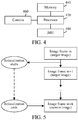
FIG. 5 is a schematic diagram of the timing of a relocalization process according to an exemplary embodiment of this application. -
FIG. 6 is a flowchart of a relocalization method in a camera pose tracking process according to an exemplary embodiment of this application. -
FIG. 7 is a diagram showing a calculation principle of a normal tracking process according to an exemplary embodiment of this application. -
FIG. 8 is a diagram showing a calculation principle of a relocalization process according to an exemplary embodiment of this application. -
FIG. 9 is a flowchart of a relocalization method in a camera pose tracking process according to an exemplary embodiment of this application. -
FIG. 10 is a schematic diagram of comparison among the first anchor image, a target image, and a first-order keyframe according to an exemplary embodiment of this application. -
FIG. 11 is a flowchart of a relocalization method in a camera pose tracking process according to an exemplary embodiment of this application. -
FIG. 12 is a schematic diagram of the principle of a relocalization method according to an exemplary embodiment of this application. -
FIG. 13 is a schematic diagram of the working principle of a back-end program according to an exemplary embodiment of this application. -
FIG. 14 is a schematic diagram of the working principle of a front-end program according to an exemplary embodiment of this application. -
FIG. 15 is a block diagram of a relocalization apparatus in a camera pose tracking process according to an exemplary embodiment of this application. -
FIG. 16 is a block diagram of an electronic device according to an exemplary embodiment of this application. - To make objectives, technical solutions, and advantages of this application clearer, the following further describes in detail implementations of this application with reference to the accompanying drawings.
- Several nouns used in this application are briefly described first:
AR is a technology that as a camera acquires an image, a camera pose parameter of the camera in the real world (or referred to as the three-dimensional world or the actual world) is calculated in real time, and a virtual element is added according to the camera pose parameter to the image acquired by the camera. The virtual element includes, but is not limited to, an image, a video, and a three-dimensional model. The objective of the AR technology is to overlay the virtual world on a screen onto the real world to perform interaction. The camera pose parameter includes a rotation matrix and a displacement vector. The rotation matrix is used to represent a rotation angle of the camera in the real world. The displacement vector is used to represent a displacement distance of the camera in the real world. - For example, referring to
FIG. 1 and FIG. 2 , a device adds a figure of a virtual human to an image photographed by a camera. As the camera moves in the real world, the image photographed by the camera changes, and a photographing position of the virtual human also changes, thereby simulating an effect that the virtual human is still in the image and the camera photographs the image and the virtual human while the position and pose are changing, so as to present a realistic three-dimensional picture to a user. - An anchor-switching AR system is an AR system that determines a camera pose parameter in a natural scene based on camera pose tracking of a plurality of consecutive anchor images and overlays the virtual world according to the camera pose parameter onto an image acquired by a camera.
- An inertial measurement unit (IMU) is an apparatus configured to measure tri-axial attitude angles (or angular velocities) and accelerations of an object. Generally, the IMU includes three uniaxial accelerometers and three uniaxial gyroscopes. The accelerometer is configured to detect an acceleration signal of an object on each coordinate axis of a three-dimensional coordinate system, to calculate the displacement vector (errors may accumulate as time elapses). The gyroscopes are configured to detect a rotation matrix of the object in the three-dimensional coordinate system. Optionally, the IMU includes a gyroscope, an accelerometer, and a geomagnetic sensor.
- Schematically, a manner of establishing a three-dimensional coordinate system is as follows: 1. The X axis is defined by a vector product Y∗Z, and a direction tangential to the ground at a current position of the device on the X axis points to the east. 2. A direction tangential to the ground at the current position of the device on the Y axis points to the north pole of the geomagnetic field. 3. The Z axis points to the sky and is perpendicular to the ground.
- Relocalization: In a camera pose tracking process based on an ith anchor image, in a case that feature point tracking performed on a target image relative to an ith anchor image fails and the camera pose tracking process cannot be successfully performed, feature point tracking is performed again on a target image relative to another image (the first anchor image or another representative keyframe), so that in a case that feature point tracking succeeds, positioning of a camera pose of the camera during acquisition of the target image is implemented according to a regained tracking process.
- This application provides a relocalization method applicable to an anchor-switching AR system algorithm. In the anchor-switching AR system algorithm, in a process of determining a camera pose, a movement process of a camera is divided into at least two tracking processes to perform tracking, and each tracking process corresponds to a respective anchor image. Specifically, in a tracking process corresponding to an ith anchor image, in a case that a tracking effect of a current image relative to the ith anchor image is poorer than a preset condition (for example, a quantity of feature points that can be obtained through matching is less than a preset threshold), a previous image of the current image is determined as an (i+1)th anchor image, and an (i+1)th tracking process is started, i being a positive integer. Schematically,
FIG. 3 is a schematic diagram of the principle of the anchor-switching AR system algorithm according to an exemplary embodiment of this application. Anobject 320 exists in the real world, adevice 340 provided with a camera is held by a user to move, and a plurality of frames ofimage 1 to 6 including theobject 320 are photographed during movement. The device determines theimage 1 as the first anchor image (born-anchor or born-image) and records an initial pose parameter. The initial pose parameter may be a pose parameter of the camera during acquisition of animage 1 and acquired by an IMU. Feature point tracking is then performed on theimage 2 relative to theimage 1, and a pose parameter of the camera during the photographing of theimage 2 is calculated according to the initial pose parameter and a feature point tracking result. Feature point tracking is performed on theimage 3 relative to theimage 1, and a pose parameter of the camera during the photographing of theimage 3 is calculated according to the initial pose parameter and a feature point tracking result. Feature point tracking is performed on theimage 4 relative to theimage 1, and a pose parameter of the camera during the photographing of theimage 4 is calculated according to the initial pose parameter and a feature point tracking result. - Feature point tracking is then performed on the
image 5 relative to theimage 1. Theimage 4 is determined as the second anchor image in a case that the effect of feature point tracking is poorer than a preset condition (for example, there is a relatively small quantity of matching feature points). Feature point tracking is performed on theimage 5 relative to theimage 4, and a displacement change amount of the camera during the photographing of theimage 4 and the photographing of theimage 5 is calculated. A displacement change amount of the camera between the photographing of theimage 4 and the photographing of theimage 1 and the initial pose parameter are then combined to calculate a pose parameter of the camera during the photographing of theimage 5. Feature point tracking is then performed on theimage 6 relative to theimage 4. The rest is deduced by analogy. A previous frame of image of the current image may be determined as a new anchor image in a case that the effect of feature point tracking of the current image deteriorates, and feature point tracking is performed again after switching to the new anchor image. - Optionally, an algorithm based on a visual odometry principle such as a feature point method or a direct method may be used for feature point tracking. However, in various abnormal scenarios such as that the camera moves relatively intensely, moves toward an intense light source, and moves toward a white wall in a tracking process, a loss phenomenon may occur in the foregoing tracking process of an anchor-switching AR system. The loss phenomenon means that sufficient feature points cannot be obtained from a target image through matching, resulting in a feature point tracking failure. In this case, relocalization needs to be performed on the target image. However, a relocalization process consumes a relatively long time, and as a result a main thread may be blocked, and a relocalization result may be obtained only after several frames of image.
-
FIG. 4 is a structural block diagram of an electronic device according to an exemplary embodiment of this application. The electronic device includes aprocessor 420, amemory 440, acamera 460, and anIMU 480. - The
processor 420 includes one or more processing cores, for example, a 4-core processor, an 8-core processor, and the like. Theprocessor 420 is configured to execute at least one of an instruction, a code, a code segment, and a program stored in thememory 440. - The
processor 420 is electrically connected to thememory 440. Optionally, theprocessor 420 is connected to thememory 440 by a bus. Thememory 440 stores one or more instructions, codes, code segments and/or programs. The instruction, code, code segment and/or program is executed by theprocessor 420 to implement a relocalization method in a camera pose tracking process provided in the following embodiments. - The
processor 420 is further electrically connected to thecamera 460. Optionally, theprocessor 420 is connected to thecamera 460 by a bus. Thecamera 460 is a sensing device having an image acquisition capability. Thecamera 460 may also be referred to as a photosensitive device, among other names. Thecamera 460 has a capability of consecutively acquiring images or repeatedly acquiring images. Optionally, thecamera 460 is disposed inside or outside the device. - The
processor 420 is further electrically connected to theIMU 480. Optionally, theIMU 480 is configured to: acquire a pose parameter of the camera at an interval of a predetermined time, and record a time stamp of each group of pose parameters during acquisition. The pose parameter of the camera includes a displacement vector and a rotation matrix. The rotation matrix acquired by theIMU 480 is relatively accurate, and the acquired displacement vector may have a relatively large error due to an actual environment. - An embodiment of this application provides a relocalization architecture of "a front-end program+a back-end program". The front-end program is run in a main thread, and the back-end program is run in another thread. The front-end program is used to sequentially perform a camera pose tracking process on a plurality of anchor images. The back-end program is used to perform relocalization on a target image in a case that the target image satisfies a relocalization condition. Inter-process communication is implemented between the front-end program and the back-end program by using a result module. In the process of implementing this application, the inventor finds that in a case that a relocalization process is executed in the front-end program, because the time of the relocalization process is usually relatively long, the normal operation of the front-end program may be blocked. However, in a case that the relocalization process is executed in the back-end program, because the back-end program cannot control the time of obtaining a successful relocalization result, a relocalization result before several frames of image may be obtained and cannot be directly used for relocalization of a current image. As shown in
FIG. 5 , it is assumed that the front-end program processes an image frame m (referred to as a target image in the following embodiments), the image frame m is prone to a loss phenomenon, and the back-end program starts to perform relocalization on the image frame m. In a case that the back-end program obtains a relocalization result of the image frame m, that is, relocalization ends, the front-end program already starts to process an image frame m+k, the relocalization result of the image frame m cannot be directly used as a result for correcting the image frame m+k. For this, this application provides the following embodiments. -
FIG. 6 is a flowchart of a relocalization method in a camera pose tracking process according to an embodiment of this application. This embodiment is described by using an example in which the relocalization method is applied to the device shown inFIG. 4 . The method includes the following steps:
Step 601: A front-end program obtains a target image acquired after an ith anchor image in a plurality of anchor images, i being a positive integer. - A camera in the device acquires frames of image at an interval of a preset time to form an image sequence. Optionally, the camera acquires frames of image at an interval of a preset time in a movement (translation and/or rotation) process to form an image sequence.
- Optionally, the front-end program determines the first frame of image in the image sequence (or one frame of image satisfying a predetermined condition in several frames of image in the front) as the first anchor image, performs feature point tracking on a subsequently acquired image relative to the first anchor image, and calculates a camera pose parameter of the camera according to a feature point tracking result. In a case that the effect of feature point tracking of a current image is poorer than a preset condition (for example, a relatively small quantity of feature points are obtained through matching), a previous frame of image of the current image is determined as the second anchor image, feature point tracking is performed on a subsequently acquired image relative to the second anchor image, and the camera pose parameter of the camera is calculated according to a feature point tracking result. The rest is deduced by analogy. The front-end program may sequentially perform camera pose tracking on a plurality of consecutive anchor images.
- Step 602: The front-end program switches the target image to an (i+1)th anchor image in a case that the target image satisfies a relocalization condition.
- The device determines whether the current image satisfies the relocalization condition. The relocalization condition is used to indicate that a tracking process of the current image relative to the ith anchor image fails, or, the relocalization condition is used to indicate that an accumulated error in historical tracking processes is already greater than the preset condition.
- In an optional embodiment, the device tracks the current image relative to the ith anchor image, and determines that a tracking process of the current image relative to the ith anchor image fails, and the current image satisfies the relocalization condition in a case that a feature point matching the ith anchor image does not exist in the current image or a quantity of feature points in the current image that match the ith anchor image is less than a first quantity.
- In another optional embodiment, the device determines that an accumulated error in historical tracking processes is already greater than the preset condition in a case that the device determines that a quantity of frames between the current image and an image in previous relocalization is greater than a second quantity, or the device determines that an accumulated error in historical tracking processes is already greater than the preset condition in a case that the device determines that a quantity of anchor images between the ith anchor image and the first anchor image is greater than a third quantity.
- Specific condition content of the relocalization condition is not limited in this embodiment.
- In a case that the front-end program determines that the target image satisfies the relocalization condition, the front-end program switches the target image to an (i+1)th anchor image, and temporarily uses a camera pose parameter including Rold and Told (there may be an error) acquired by an IMU as a reference pose parameter of the (i+1)th anchor image. Rold is used to represent a rotation matrix of the camera from the first anchor image to the (i+1)th anchor image (the target image), and Told is used to represent a displacement vector of the camera from the first anchor image to the (i+1)th anchor image (the target image).
- Step 603: The front-end program transmits the target image to a back-end program.
- Optionally, the front-end program uses a result module to transmit the target image to the back-end program. The result module is a storage space shared by the front-end program and the back-end program. The back-end program is used to perform relocalization on the target image relative to another image. The another image includes the first anchor image and/or a representative keyframe with past successful relocalization.
- Step 604: The front-end program obtains a current image acquired after the target image, and performs feature point tracking on the current image relative to the target image to obtain a first pose parameter.
- After providing the target image to the back-end program, the front-end program obtains a current image acquired after the (i+1)th anchor image (a target image), and performs feature point tracking on the current image relative to the target image, to obtain the first pose parameter.
- The first pose parameter is used to represent a change amount of a camera pose from the target image to the current image. The first pose parameter includes a first rotation matrix Rca and a first displacement vector Tca. Rca is used to represent a rotation matrix of the camera from the (i+1)th anchor image (the target image) to the current image, and Tca is used to represent a displacement vector of the camera from the (i+1)th anchor image (the target image) to the current image.
- Step 605: The back-end program performs relocalization on the target image to obtain a second pose parameter.
- In parallel with
step 604, the back-end program performs relocalization on the target image relative to another image to obtain the second pose parameter. - The second pose parameter is used to represent a change amount of a camera pose from the first anchor image to the target image. The second pose parameter includes a second rotation matrix Rrelocalize and a second displacement vector Trelocalice. Rrelocalice is used to represent a rotation matrix of the camera from the first anchor image to the (i+1)th anchor image (the target image) and is a correction value that is obtained through relocalization and is used for Rold. Trelocalice is used to represent a displacement vector of the camera from the first anchor image to the (i+1)th anchor image (the target image) and is a correction value that is obtained through relocalization and used for Told.
- Step 606: The back-end program transmits the second pose parameter to the front-end program.
- Optionally, after performing a relocalization process on the target image, the back-end program transmits the second pose parameter obtained through relocalization to the second pose parameter by using the result module.
- Step 607: The front-end program calculates a current pose parameter of the current image according to the first pose parameter and the second pose parameter.
- Optionally, the front-end program performs calculation according to the following formula to obtain a current pose parameter including Rm+k and Tm+k as follows:

- Optionally, s is preset value, or, s is a projected feature point obtained after the front-end program maps an initial feature point in the first anchor image to the target image, and a scale corresponding to the target image is calculated according to an average depth of the projected feature point.
- In conclusion, by means of the relocalization method provided in this embodiment, a front-end program switches a target image to an (i+1)th anchor image. As a back-end program performs relocalization on the target image, the front-end program performs camera pose tracking based on the (i+1)th anchor image in parallel to obtain a first pose parameter. The first pose parameter and the second pose parameter are used to correct a positioning result of a current image in a case that a relocalization result (a second pose parameter) is obtained during processing of the current image by the front-end program, thereby resolving a problem that the back-end program cannot control the time of obtaining a successful relocalization result, and a relocalization result obtained several frames of image before cannot be directly used for relocalization of a current image. Even if it takes a relatively long time for the back-end program to obtain a relocalization result, two pose change amounts can be added to correct the positioning result of the current image, thereby ensuring a relatively adequate relocalization effect.
- To describe the foregoing relocalization principle from another perspective, a normal tracking process and a relocalization success process are described with reference to
FIG. 7 and FIG. 8 . - Normal tracking process (
FIG. 7 ): In a camera pose tracking process based on an ith anchor image, it is set that the ith anchor image has a pose change amount including R_i_old and T_i_old relative to the first anchor image. In a case that feature point tracking is performed on an image frame m relative to the ith anchor image succeeds, to obtain a pose change amount including Rcal and Tcal, a camera pose parameter of the image frame m is calculated by using the following formula:
- In a case that feature point tracking performed on the image frame m+k relative to the ith anchor image succeeds, to obtain a pose change amount including Rca2 and Tca2, a camera pose parameter of the image frame m+k is calculated by using the following formula:

- Successful relocalization (
FIG. 8 ): In a camera pose tracking process based on the ith anchor image, a target image is lost, and the front-end program switches the target image to an (i+1)th anchor image. A reference pose parameter acquired by an IMU is used as a pose change amount including Rold and Told of the (i+1)th anchor image relative to the first anchor image. In a case that relocalization performed on the target image by the back-end program succeeds, to obtain a relocalization result (Rrelocalize and Trelocalice), a camera pose parameter of the current image (the image frame m+k) is calculated by using the following formula:
- In the optional embodiment based on
FIG. 6 , the back-end program performs relocalization on the target image relative to the first anchor image, to obtain the second pose parameter. As shown inFIG. 9 , the foregoingstep 605 includes the following sub-steps: -
Step 605a: Obtain an initial feature point and an initial pose parameter in the first anchor image, the initial pose parameter being used to indicate a camera pose of a camera during acquisition of the first anchor image. - The back-end program attempts to perform feature point tracking on the current image relative to the first anchor image. In this case, the device obtains a cached initial feature point and initial pose parameter in the first anchor image, the initial pose parameter being used to indicate a camera pose of the camera during acquisition of the first anchor image.
-
Step 605b: Perform feature point tracking on the target image relative to the first anchor image, to obtain a target feature point matching the initial feature point. - Optionally, each matching feature point pair includes one initial feature point and one target feature point that match each other.
- A tracking algorithm based on visual odometry may be used for feature point tracking. This is not limited in this application. In an embodiment, a Kanade-Lucas (KLT) optical flow tracking algorithm is used for feature point tracking. In another embodiment, for feature point tracking, a SIFT feature descriptor extracted based on a scale-invariant feature transform (SIFT) algorithm and an ORB feature descriptor extracted based on an oriented FAST and rotated BRIEF (ORB, fast feature point extraction and description) algorithm are used to perform feature point tracking. In this application, a specific algorithm for feature point tracking is not limited, and a feature point method or a direct method may be used for a feature point tracking process.
- In an embodiment, the back-end program performs feature point extraction on the first anchor image, to obtain N initial feature points. The device further performs feature point extraction on the target image, to obtain M candidate feature points. The device then matches the M candidate feature points one by one against the N initial feature points, to determine at least one matching feature point pair. Each matching feature point pair includes an initial feature point and a target feature point. The initial feature point is a feature point in the first anchor image, and the target feature point is a candidate feature point that is in the target image and has the highest matching degree with an ith initial feature point.
- Optionally, a quantity of initial feature points is greater than or equal to a quantity of target feature points. For example, there are 450 initial feature points, and there are 320 target feature points.
-
Step 605c: Calculate a second pose parameter of a change of the camera from the initial pose parameter to a target pose parameter according to the initial feature point and the target feature point, the target pose parameter being used to represent a camera pose of the camera during acquisition of the target image. - Optionally, the device calculates a homography matrix between two frames of image according to the initial feature point and the target feature point; and decomposes the homography matrix to obtain a pose change amount including Rrelocalize and Trelocalize of the change of the camera from the initial pose parameter to the target pose parameter.
- The homography matrix describes a mapping relationship between two planes. The homography matrix may be used to perform movement estimation in a case that feature points in the natural scenario (the real environment) all fall in a same physical plane. The device uses ransac to decompose the homography matrix in a case that there are at least four pairs of matching initial feature points and target feature points, to obtain a rotation matrix Rrelocalize and a translation vector Trelocalize.
- Rrelocalize is a rotation matrix of the change of the camera from the initial pose parameter to the target pose parameter, and Trelocalize is a displacement vector of the change of the camera from the initial pose parameter to the target pose parameter.
-
Step 605d: Perform relocalization according to the initial pose parameter and the pose change amount to obtain the second pose parameter. - After performing conversion on the initial pose parameter by using the pose change amount, the device performs relocalization to obtain the second pose parameter including Rrelocalize and Trelocalice, so as to calculate the camera pose of the camera during acquisition of the target image.
- In the relocalization method shown in
FIG. 8 , relocalization is performed on a target image relative to the first anchor image. In the method, relocalization may fail in some scenarios. For example, in a case that a photographing pose corresponding to the target image is greatly different from a photographing pose of the first anchor image, relocalization implemented by directly establishing a match between the target image and the first anchor image may fail. Schematically, it is set that the picture (1) inFIG. 10 is the first anchor image, and the picture (2) inFIG. 10 is the target image. Because there is an excessively small overlapping area between the target image and the first anchor image, and a sufficient matching degree is not reached, relocalization directly performed on the target image and the first anchor image fails. In an optional embodiment of this application, the picture (3) inFIG. 10 is introduced as a first-order keyframe, and relocalization is performed on the target image relative to a first-order keyframe, so that the success probability of relocalization can be improved. - In the embodiment based on
FIG. 6 , the back-end program performs relocalization on the target image relative to the first anchor image, to obtain the second pose parameter. As shown inFIG. 11 , the foregoingstep 605 includes the following sub-steps:
Step 6051: Select a target keyframe from a keyframe database. - The keyframe database stores image information of at least one keyframe. The keyframe is an image that has successful relocalization in a historical camera pose tracking process and has a first relocalization result relative to the first anchor image.
- There may be more than one relocalization process in a camera pose tracking process. The device chooses some representative images from images with successful relocalization as keyframes and saves the keyframes in the keyframe database. The keyframe database is a database configured to store a keyframe. The keyframe database stores image information of a plurality of keyframes. The image information includes an image of the keyframe, a feature point in the keyframe, and a first relocalization result corresponding to the keyframe. Optionally, the image information further includes: the first global descriptor of the keyframe. The first global descriptor is used to represent the image of the keyframe feature by using a small data amount. Alternatively, the first global descriptor is used to uniquely represent the image of the keyframe feature by using the small data amount.
- In a case that relocalization is performed on a target image, the back-end program chooses a target keyframe from the keyframe database. Optionally, the target keyframe is an image at the smallest image distance from the target image in the keyframe database. In different embodiments, the image distance can be represented by any form of an image similarity, an image feature similarity, and a distance between matching feature points. This is not limited in this embodiment of this application.
- In an embodiment, the device chooses a target keyframe from the keyframe database by using a similarity between the first global descriptor of the keyframe and the second global descriptor of the target image. In another embodiment, because an IMU can acquire a reference pose parameter (there may be an error) of the camera during acquisition of the target image, the device chooses a target keyframe from the keyframe database by using the similarity between the first pose parameter of the keyframe and the reference pose parameter of the target image.
- Step 6052: Perform relocalization on the target image relative to the target keyframe, to obtain a second relocalization result.
- After choosing the target keyframe from the keyframe database, the device performs relocalization on the target image relative to the target keyframe. Optionally, a process of relocalization includes the following steps:
- 1: Obtain a keyframe feature point and a first relocalization result of the target keyframe.
The keyframe database stores a keyframe feature point on each keyframe and a tracking result of a first camera pose. Optionally, the keyframe feature point is represented by using a SIFT feature descriptor or an ORB feature descriptor. The first relocalization result is a camera pose parameter of the camera during acquisition of a keyframe (referred to as a keyframe pose parameter for short), or, the first relocalization result is a pose change amount including a rotation matrix and a displacement vector of the camera pose parameter of the camera during acquisition of a keyframe relative to a camera pose parameter of the camera during acquisition of the first anchor image. - 2. Perform feature point tracking on the target image relative to a target keyframe database, to obtain a target feature point matching the keyframe feature point.
Optionally, each matching feature point pair includes one keyframe feature point and one target feature point that match each other.
A tracking algorithm based on visual odometry may be used for feature point tracking. This is not limited in this application. In an embodiment, a KLT optical flow tracking algorithm is used for feature point tracking. In another embodiment, for feature point tracking, a SIFT feature descriptor extracted based on a SIFT algorithm and an ORB feature descriptor extracted based on an ORB algorithm are used to perform feature point tracking. In this application, a specific algorithm for feature point tracking is not limited, and a feature point method or a direct method may be used for a feature point tracking process.
In an embodiment, because the target keyframe is an image with successful relocalization, the device has already performed feature point extraction on the target keyframe in a historical process, to obtain N keyframe feature points. The device further performs feature point extraction on the target image, to obtain M candidate feature points; and the device then matches the M candidate feature points one by one against the N initial feature points, to determine at least one matching feature point pair. Each matching feature point pair includes a keyframe feature point and a target feature point. The keyframe feature point is a feature point on the target keyframe, and the target feature point is a candidate feature point having the highest matching degree with the keyframe feature point in the target image.
Optionally, a quantity of the keyframe feature points is greater than or equal to a quantity of target feature points. For example, there are 480 keyframe feature points, and there are 350 target feature points. - 3. Calculate a pose change amount of a change of the camera from the keyframe pose parameter to the second pose parameter according to the keyframe feature point and the target feature point, the second pose parameter being used to represent the camera pose of the camera during acquisition of the target image.
- Optionally, the device calculates a homography matrix between two frames of image according to the keyframe feature point and the target feature point; and decomposes the homography matrix to obtain the pose change amount including Rcm and Tcm of the change of the camera from the keyframe pose parameter to the second pose parameter, and use the pose change amount including Rcm and Tcm as the second relocalization result.
- Rcm is a rotation matrix of the change of the camera from the keyframe pose parameter to the second pose parameter, and Tcm is a displacement vector of the change of the camera from the keyframe pose parameter to the second pose parameter.
- Step 6053: Calculate a second pose parameter of the camera during acquisition of the target image according to the first relocalization result and the second relocalization result.
- It is assumed that the first relocalization result includes Rmf and Tmf. Rmf is a rotation matrix of the change of the camera from the initial pose parameter to the keyframe pose parameter, and Tmf is the displacement vector of the change of the camera from the initial pose parameter to the keyframe pose parameter. The second relocalization result includes Rcm and Tcm. Rcm is the rotation matrix of the change of the camera from the keyframe pose parameter to the second pose parameter, and Tcm is the displacement vector of the change of the camera from the keyframe pose parameter to the second pose parameter. The target pose parameter of the camera during acquisition of the target image is calculated by using the following formula:

- The keyframe database includes: a first-order keyframe with successful first-order relocalization relative to the first anchor image, and/or, and an nth-order keyframe with successful nth order relocalization relative to the (n-1)th-order keyframe in the keyframe database, n being an integer greater than 1. The foregoing is described by using only an example of the first-order relocalization image. A first relocalization result of an nth-order keyframe may be obtained by performing multiplication on a plurality of pose change amounts. Details are not described herein again in this application.
- In the optional embodiment based on
FIG. 6 , a projected feature point obtained after the front-end program maps an initial feature point in the first anchor image onto the target image, and a process of calculating a scale corresponding to the target image according to an average depth of the projected feature point is as follows: - 1. Obtain two-dimensional coordinates of the initial feature point in the first anchor image.
The front-end program extracts and caches the two-dimensional coordinates of the initial feature point in the first anchor image in advance. The two-dimensional coordinates are homogeneously represented. - 2. Perform back projection on the two-dimensional coordinates of the initial feature point, to obtain first three-dimensional coordinates Xborn of the initial feature point in the three-dimensional space.
The front-end program converts the two-dimensional coordinates of the initial feature point into three-dimensional space by using the following formula, to obtain the first three-dimensional coordinates Xborn of the initial feature point in the three-dimensional space:
- 3. Perform three-dimensional rotation and translation on the first three-dimensional coordinates Xborn by using the following formula, to obtain the second three-dimensional coordinates Xcurrent corresponding to the initial feature point in the target image;

- 4. Project the second three-dimensional coordinates Xcurrent onto the target image, to obtain two-dimensional coordinates of the projected feature point in the target image.
The front-end program projects the second three-dimensional coordinates Xcurrent onto the target image by using the following formula, to obtain two-dimensional coordinates Xcurrent of the projected feature point in the target image:
- 5. Calculate a scale s of the target image according to an average depth of the projected feature point in the target image.
- In the optional embodiment based on
FIG. 6 , a result module is provided between the front-end program and the back-end program between. The result module is a storage space shared by the front-end program and the back-end program. As shown inFIG. 12 , the result module includes a relocalization list, a result-flag, and a result storage location. Optionally, the result module further includes an expand-map list, an abandon time. - The relocalization list is used to store a target image that requires relocalization. Optionally, there is at most one target image in the relocalization list within the same time. In a case that the front-end program needs to perform relocalization, the target image is written into the relocalization list.
- The result-flag is used to store a working status of the back-end program. The working status includes ready, have-result, and still-running. Ready represents that the back-end program is in an activated and idle state. Have-result represents that the back-end program has completed calculation of last relocalization, including that relocalization succeeds (OK) or relocalization fails. Still-running represents that calculation is being performed and not completed.
- The result storage location is used to store the second pose parameter including Rrelocalize and Trelocalice in a case that relocalization succeeds.
- The expand-map list is used to store a candidate image of a keyframe database. The front-end program imports an image into the expand-map list during a normal camera tracking process for the back-end program to expand the keyframe database.
- The abandon time is used to store the time at which the front-end program switches an anchor image the last time. For example, in a case that the front-end program sets the target image as the (i+1)th anchor image, the front-end program records the switching time of the (i+1)th anchor image to the abandon time.
- In an embodiment with reference to
FIG. 12 , the back-end program is a thread kept running in the back end. The back-end program and the front-end program are run in different threads, and the result module is used to implement inter-process communication. The back-end program uses while (1) to repeatedly perform the step inFIG. 13 :
Step 1200: Wait for a new image. - The back-end program monitors the relocalization list and the expand-map list in the result module.
- Step 1201: Determine whether the relocalization list is empty.
- In a case that the relocalization list is empty, it is determined that the front-end program does not have a target image that requires relocalization, and
step 1202 is performed. In a case that the relocalization list is not empty, it is determined that the front-end program has a target image that requires relocalization, andstep 1204 is performed. - Step 1202: Determine whether the expand-map list is empty.
-
Step 1203 is performed in a case that the expand-map list is not empty.Step 1200 is performed again in a case that the expand-map list is empty. - Step 1203: Expand a keyframe database.
- The back-end program uses the candidate image in the expand-map list to expand keyframes in the keyframe database, so that keyframes in the keyframe database are added or updated.
- Step 1204: Set the result-flag to still-running.
- The back-end program sets the result-flag to still-running, and then starts to perform relocalization on the target image.
- Step 1205: Perform relocalization on a target image that requires relocalization.
- Refer to the description in
FIG. 9 orFIG. 11 . Details are not described herein again in this embodiment. Optionally, the back-end program first performs relocalization on the target image relative to the first anchor image, and performs relocalization again on the target image relative to the keyframe database in a case that relocalization fails. Alternatively, the back-end program performs relocalization in parallel on the target image relative to the first anchor image, and performs relocalization on the target image relative to the keyframe database. - Step 1206: Determine whether the relocalization process succeeds.
-
Step 1207 is performed in a case that relocalization succeeds.Step 1208 is performed in a case that relocalization fails. - Step 1207: Determine whether the time at which the relocalization succeeds is earlier than the abandon time.
- The abandon time is used to indicate the time at which the front-end program switches an anchor image the last time.
- In a case that the time at which relocalization succeeds is earlier than the abandon time, it indicates that after switching the target image to the (i+1)th anchor image, the front-end program has already switched the anchor image once or several times, the current relocalization result is in an invalid state, and
step 1208 is performed. In a case that the time at which the relocalization succeeds is later than the abandon time, the current relocalization result is a valid state, andstep 1209 is performed. - Step 1208: Set the result-flag to fail.
- The back-end program sets the result-flag to fail.
- Step 1209: Set the result-flag to success.
- The back-end program sets the result-flag to OK, and writes the second pose parameter including Rrelocalize and Trelocalice into the result module.
- In an embodiment with reference to
FIG. 12 , a front-end program is run in a main thread and is responsible for sequentially performing a camera tracking process of a plurality of anchor images. The back-end program and the front-end program are run in different threads. The result module is used to implement inter-process communication. flagl and flag2 are set in the front-end program. flag1 is used to represent whether relocalization needs to be performed, and flag2 is used to represent that relocalization fails and a marker needs to be switched again. The front-end program is used to perform the following steps, as shown inFIG. 14 :
Step 1300: Perform camera pose tracking based on the plurality of anchor images. - The front-end program is responsible for a camera pose tracking process based on the plurality of anchor images. Schematically, it is assumed that the front-end program is performing a camera pose tracking process of an ith anchor image.
- Step 1301: Determine whether there is a tracking result.
- The front-end program obtains a target image acquired after the ith anchor image and after feature point tracking is performed on a target image relative to the ith anchor image, and determines whether there is a tracking result.
Step 1302 is performed in a case that there is a tracking result.Step 1303 is performed in a case that there is no tracking result. - Step 1302: Set flag1 to false.
- The camera pose tracking process in
step 1300 continues to be performed. - Step 1303: Set flag1 to true.
- The front-end program sets flagl to true, representing that relocalization needs to be performed on the target image.
- Step 1304: Detect the status of flag1.
- During processing of each frame of image, the front-end program further detects the status of flag1.
Step 1305 is performed in a case that the status of flag1 is false. The front-end program transmits the target image to the expand-map list for use by the back-end program to expand the keyframe database.Step 1306 is performed in a case that the status of flag1 is true. The front-end program considers that the target image being processed requires relocalization and detects the state of flag2. -
Step 1307 is performed in a case that the status of flag2 is false, representing that the last relocalization succeeds.Step 1313 is performed in a case that the status of flag2 is true, representing that the last relocalization fails. - Step 1307: Detect whether the running status of the back-end program is ready.
- The front-end program reads the result-flag in the result module. In a case that the result-flag is ready, it indicates that the back-end program is in an idle state, and relocalization may be performed on the target image.
- Step 1308: Switch to an (i+1)th anchor image, transmit the abandon time, and transmit the target image to the relocalization list.
- The front-end program switches the target image to the (i+1)th anchor image, and writes the switching time into the abandon time in the result module.
- Step 1309: Attempt to obtain a relocalization result of the back-end program.
- The front-end program reads the result-flag in the result module.
Step 1310 is performed in a case that the result-flag is still-running.Step 1311 is performed in a case that the result-flag is have-result_ok.Step 1312 is performed in a case that the result-flag is have-result_fails. - Step 1310: Conduct another transaction.
- The front-end program may perform a feature point tracking process on a current image after a target image in a calculation process in which the back-end program performs relocalization on the target image.
- Step 1311: Set
flag 1 to fail. - flagl is set to fail in a case that relocalization of the target image succeeds, representing that relocalization is not required, and a camera tracking process based on the (i+1)th anchor image is performed.
- Step 1312: Set flag2 to success.
- flag2 is set to success in a case that relocalization of the target image fails.
- Step 1313: Switch to an (i+2)th anchor image, and transmit the abandon time.
- In a case that the front-end program obtains a current image after a target image, in a case that flag1 is true and flag2 is true, it represents that a last relocalization process of the back-end program fails. For example, a relocalization process of the target image fails. The front-end program needs to transmit the current image after the target image to the relocalization list, so that the back-end program initiates a relocalization process on the current image. In this case, the front-end program switches the current image to an (i+2)th anchor image, and write the switching time into the abandon time in the result module again.
- In the optional embodiment based on
FIG. 12 , the back-end program uses the candidate image in the expand-map list to expand a keyframe in a keyframe database, including the following steps:
Step 1: Obtain a latest candidate image with successful relocalization. - In an initial state, the keyframe database may be empty, and the back-end program only uses the first anchor image as an anchor image for relocalization. With the execution of the entire camera tracking process, there are an increasing large number of images with successful relocalization relative to the first anchor image (or a keyframe that has been added to the keyframe database).
- Every time relocalization succeeds, the back-end program uses the image with successful relocalization as a candidate image that may be added to the keyframe database. Optionally, the successful relocalization includes: successful relocalization relative to the first anchor image, or, successful relocalization relative to an existing keyframe in the keyframe database.
- The back-end program chooses some images from the candidate images as keyframes and adds the keyframes to the keyframe database.
- Step 2: Determine whether the candidate image satisfies an addition condition, the addition condition including: a first distance between the candidate image and the first anchor image is greater than a first threshold, and/or, a second distance between the candidate image and a keyframe added last time is greater than a second threshold.
- Optionally, there needs to be a particular distance between a currently added keyframe and the first anchor image, because in a case that two images are relatively close, the relocalization effect of using the currently added keyframe is not significantly different from that of directly using the first anchor image.
- The back-end program calculates the first distance between the candidate image and the first anchor image. The first distance is used to represent an image similarity or a camera pose similarity between the candidate image and the first anchor image. In this application, a specific calculation manner of the first distance is not limited. In an optional embodiment, for an initial feature point in the first anchor image, a target feature point matching the initial feature point exists in the candidate image. One initial feature point and a corresponding target feature point constitute a matching feature point pair. An L2 distance (a Euclidean distance corresponding to the norm of L2) is calculated according to each matching feature point pair. An average value of all L2 distances is used as the first distance between the candidate image and the first anchor image. For example, the first threshold is 50 pixels. In a case that the first distance between the candidate image and the first anchor image is greater than 50 pixels, the candidate image is added to the keyframe database.
- Optionally, there needs to be a particular distance between the currently added keyframe and the keyframe added last time, because in a case that two images are relatively close, the relocalization effect of using the currently added keyframe is not significantly different from that of using the keyframe added last time.
- The back-end program calculates the second distance between the candidate image and the keyframe added last time. The second distance is used to represent an image similarity or a camera pose similarity between the candidate image and the keyframe added last time. In this application, a specific calculation manner of the second distance is not limited. In an optional embodiment, a quantity of relocalization images between the candidate image and the keyframe added last time is used as the second distance. For example, the second threshold is 10. In a case that the quantity of relocalization images between the candidate image and the keyframe added last time exceeds 10, the candidate image is added to the keyframe database.
-
Step 3. Add the candidate image to the keyframe database in a case that the candidate image satisfies the addition condition. - In a case that it is determined that the candidate image satisfies the addition condition, the candidate image is added to the keyframe database as a keyframe. Optionally, a first global descriptor of the keyframe, a keyframe feature point, a positioning result of the first relocalization are stored in the keyframe database. The first global descriptor is used to represent the image of the keyframe feature by using a small data amount, and the positioning result of the first relocalization may be represented by a keyframe pose parameter of the camera during acquisition of a keyframe or may be represented by the pose change amount of the change of the camera from the initial pose parameter to the keyframe pose parameter.
- Step 4: Skip adding the candidate image to the keyframe database in a case that the candidate image does not satisfy the addition condition.
- The candidate image is not added to the keyframe database in a case that the first distance between the candidate image and the first anchor image is less than the first threshold, or, the second distance between the candidate image and the keyframe added last time is less than the second threshold.
- Optionally, the keyframe satisfying the foregoing addition condition may be used to expand the keyframe database, but too many keyframes cause calculation amount load to a relocalization process, making it difficult to find a desired image, and therefore are not recommended in the keyframe database. In a schematic example, there are 1000 or fewer keyframes in the keyframe database.
- A similarity between the candidate image and an existing keyframe is calculated in a case that the candidate image satisfies the addition condition and a quantity of keyframes in the keyframe database reaches a maximum value (for example, 1000). A keyframe with the highest similarity is deleted from the keyframe database, and the candidate image is added to the keyframe database.
- In a schematic example, the foregoing relocalization method in a camera pose tracking process may be used in an AR program. By means of the relocalization method, a pose of a camera on an electronic device can be tracked in real time according to scene information in the real world, and a display position of an AR element in an AR application is adjusted and changed according to a tracking result. An AR program run on the mobile phone in
FIG. 1 or FIG. 2 is used as an example. In a case that a still cartoon character standing on a book needs to be displayed, no matter how a user moves the mobile phone, it is only necessary to change a display position of the cartoon character according to a pose change of a camera on the mobile phone, so that the standing position of the cartoon character on the book can be kept unchanged. - The following provides apparatus embodiments of this application. For details that are not specifically described in the apparatus embodiments, reference may be made to the foregoing method embodiments.
-
FIG. 15 is a block diagram of a relocalization apparatus in a camera pose tracking process according to an exemplary embodiment of this application. The relocalization apparatus may be implemented by software, hardware or a combination of software and hardware as an entire electronic device (or referred to as a mobile electronic device) or a part of the electronic device. The relocalization apparatus includes a front-end program module 1520 and a back-end program module 1540. The front-end program module 1520 is configured to sequentially perform a camera pose tracking process on a plurality of anchor images. - The front-
end program module 1520 is further configured to obtain a target image acquired after an ith anchor image in the plurality of anchor images, i being a positive integer. - The front-
end program module 1520 is further configured to: switch the target image to an (i+1)th anchor image in a case that the target image satisfies a relocalization condition, and transmit the target image to the back-end program module. - The front-
end program module 1520 is further configured to: obtain a current image acquired after the target image, and perform feature point tracking on the current image relative to the target image to obtain a first pose parameter, the first pose parameter being used to represent a change amount of a camera pose from the target image to the current image. - The back-
end program module 1540 is configured to: perform relocalization on the target image to obtain a second pose parameter, and transmit the second pose parameter to the front-end program, the second pose parameter being used to represent a change amount of a camera pose from the first anchor image to the target image. - The front-
end program module 1520 is configured to calculate a current pose parameter of the current image according to the first pose parameter and the second pose parameter. - In an optional embodiment, the back-
end program module 1540 is configured to perform relocalization on the target image relative to the first anchor image, to obtain the second pose parameter; and/or, the back-end program module 1540 is configured to perform relocalization on the target image relative to a keyframe in a keyframe database, to obtain the second pose parameter, the keyframe being an image the has successful relocalization and has a relocalization result relative to the first anchor image. - In an optional embodiment, the keyframe database includes:
a first-order keyframe with successful first-order relocalization relative to the first anchor image; and/or, an nth-order keyframe with successful nth-order relocalization relative to the (n-1)th-order keyframe in the keyframe database, n being an integer greater than 1. - In an optional embodiment, the front-
end program module 1520 is configured to calculate a current pose parameter of the current image according to the first pose parameter and the second pose parameter, including: - calculating a current pose parameter including Rn and Tn according to the following formula:

- the first pose parameter including a first rotation matrix Rca and a first displacement vector Tca, the second pose parameter including a second rotation matrix Rrelocalize and a second displacement vector Trelocalice, and s being a scale corresponding to the target image.
- In an optional embodiment, the front-
end program module 1520 is configured to map an initial feature point in the first anchor image onto the target image to obtain a projected feature point, and calculate a scale corresponding to the target image according to an average depth of the projected feature point. - In an optional embodiment, the apparatus further includes a
result module 1560, theresult module 1560 being a storage space shared by the front-end program module and the back-end program module, where
the front-end program module 1520 is configured to write the target image into a relocalization image list in theresult module 1560; and
the back-end program module 1540 is configured to read the target image from the relocalization image list. - In an optional embodiment, the front-
end program module 1520, configured to detect whether a result status bit in theresult module 1560 is a ready state; the front-end program module 1520 is configured to write the target image into the relocalization image list in theresult module 1560 in a case that a detection result is that the result status bit is the ready state. - In an optional embodiment, the back-
end program module 1540 is configured to write the second pose parameter into a result storage location in the result module, theresult module 1560 being a storage space shared by the front-end program module 1520 and the back-end program module 1540; and the front-end program module 1520 is configured to read the second pose parameter from the result storage location. - In an optional embodiment, the front-
end program module 1520 is configured to write the target image into an expand-map list in the result module; and the back-end program module 1540 is configured to: read the target image from the expand-map list in a case that the target image has successful relocalization and satisfies a preset condition, and add the target image to the keyframe database. - In a case that the relocalization apparatus in a camera pose tracking process provided in the foregoing embodiments implements relocalization, only divisions of the foregoing functional modules are described by using an example. During actual application, the foregoing functions may be allocated to and completed by different functional modules according to requirements, that is, the internal structure of the device is divided into different functional modules, to complete all or some of the foregoing described functions. In addition, the relocalization apparatus provided in the foregoing embodiments belongs to the same concept as the embodiments of the relocalization method. For a specific implementation process of the relocalization apparatus, refer to the method embodiments for details. Details are not described herein again.
-
FIG. 16 is a structural block diagram of anelectronic device 1600 according to an exemplary embodiment of this application. Theelectronic device 1600 may be a smart phone, a tablet computer, a Moving Picture Experts Group Audio Layer III (MP3) player, a Moving Picture Experts Group Audio Layer IV (MP4) player, a laptop computer or a desktop computer. Theelectronic device 1600 may also be referred to as a user device, a portable electronic device, a laptop electronic device, and a desktop electronic device, among other names. - Generally, the
electronic device 1600 includes aprocessor 1601 and amemory 1602. - The
processor 1601 may include one or more processing cores, for example, a 4-core processor, an 8-core processor, and the like. Theprocessor 1601 may be implemented in at least one hardware form of a digital signal processor (DSP), a field-programmable gate array (FPGA), and a programmable logic array (PLA). Theprocessor 1601 may also include a main processor and a co-processor. The main processor is a processor configured to process data in a wake-up state or is referred to as a central processing unit (CPU). The co-processor is a low power consumption processor configured to process data in a standby state. In some embodiments, theprocessor 1601 may be integrated with a graphics processing unit (GPU). The GPU is configured to render and draw content that needs to be displayed on a display. In some embodiments, theprocessor 1601 may further include an artificial intelligence (AI) processor. The AI processor is configured to process a computing operation related to machine learning. - The
memory 1602 may include one or more computer-readable storage media. The computer-readable storage medium may be non-transient. Thememory 1602 may further include a high-speed random access memory (RAM) and a non-volatile memory such as one or more magnetic disk storage devices or flash memory storage devices. In some embodiments, the non-transient computer-readable storage medium in thememory 1602 is configured to store at least one instruction. The at least one instruction is executed by theprocessor 1601 to implement the relocalization method in a camera pose tracking process provided in the method embodiments of this application. - In some embodiments, the
electronic device 1600 further optionally includes aperipheral interface 1603 and at least one peripheral. Theprocessor 1601, thememory 1602, and theperipheral interface 1603 may be connected by a bus or a signal line. Peripherals may be connected to theperipheral interface 1603 by a bus, a signal line or a circuit board. Specifically, the peripheral includes at least one of a radio frequency (RF)circuit 1604, atouch display 1605, acamera component 1606, anaudio circuit 1607, apositioning component 1608, and apower supply 1609. - The
peripheral interface 1603 may be configured to connect at least one peripheral related to an input/output (I/O) to theprocessor 1601 and thememory 1602. In some embodiments, theprocessor 1601, thememory 1602, and theperipheral interface 1603 are integrated in one same chip or circuit board. In some other embodiments, any one or two of theprocessor 1601, thememory 1602, and theperipheral interface 1603 may be separately implemented on a chip or circuit board. This is not limited in this embodiment. - The
RF circuit 1604 is configured to receive and transmit an RF signal, which is also referred to as electromagnetic signal. TheRF circuit 1604 communicates with a communications network and another communication device by using an electromagnetic signal. TheRF circuit 1604 converts an electrical signal into an electromagnetic signal for transmission, or, converts a received electromagnetic signal into an electrical signal. Optionally. TheRF circuit 1604 includes an antenna system, an RF transceiver, one or more amplifiers, a tuner, an oscillator, a DSP, a CODEC chip set, a subscriber identity module card, and the like. TheRF circuit 1604 may communicate with another electronic device by using at least one wireless communication protocol. The wireless communication protocol includes, but is not limited to, a World Wide Web, a metropolitan area network, an intranet, various generations of mobile communications networks (2G, 3G, 4G, and 5G), a wireless local area network and/or a Wireless Fidelity (Wi-Fi) network. In some embodiments. TheRF circuit 1604 may further include a Near Field Communication (NFC)-related circuit. This is not limited in this application. - The
display 1605 is configured to display a user interface (UI). The UI may include a graphic, a text, an icon, a video, and any combination thereof. In a case that thedisplay 1605 is a touch display, thedisplay 1605 further has a capability of acquiring a touch signal on or above the surface of thedisplay 1605. The touch signal may be input as a control signal into theprocessor 1601 for processing. In this case, thedisplay 1605 may further be configured to provide a virtual button and/or a virtual keyboard, which is also referred to as a soft button and/or a soft keyboard. In some embodiments, there may be onedisplay 1605, disposed on a front panel of theelectronic device 1600. In some other embodiments, there may be at least twodisplays 1605, respectively disposed on different surfaces of theelectronic device 1600 or designed to be foldable. In some other embodiments, thedisplay 1605 may be a flexible display, disposed on a curved surface or folded surface of theelectronic device 1600. Even, thedisplay 1605 may further be disposed to be a non-rectangular irregular graphic, that is, an irregular-shaped screen. Thedisplay 1605 may be manufactured by using a material such as a liquid crystal display (LCD) or an organic light-emitting diode (OLED). - The
camera component 1606 is configured to acquire an image or a video. Optionally, thecamera component 1606 includes a front-facing camera and a rear-facing camera. Generally, the front-facing camera is disposed on the front panel of the electronic device, and the rear-facing camera is disposed on the back surface of the electronic device. In some embodiments, there are at least two rear-facing cameras, which are respectively any one of a main camera, a depth-of-field camera, a wide-angle camera, a long-focus camera, to implement the integration of the main camera and the depth-of-field camera to implement a background blurring function, the integration of the main camera and the wide-angle camera to implement panoramic photography and a virtual reality (VR) photographing function or another integrated photographing function. In some embodiments, thecamera component 1606 may further include a flash. The flash may be a mono color temperature flash or may be a dual color temperature flash. The dual color temperature flash is a combination of a warm light flash and a cold light flash and may be used for light compensation at different color temperatures. - The
audio circuit 1607 may include a microphone and a loudspeaker. The microphone is configured to acquire sound waves from a user and an environment and convert the sound waves into electrical signals for input into theprocessor 1601 for processing or input into theRF circuit 1604 to implement voice communication. For stereo acquisition or noise reduction, there may be a plurality of microphones, respectively disposed at different positions of theelectronic device 1600. The microphone may be alternatively a microphone array or an omnidirectional microphone. The loudspeaker is configured to convert an electrical signal from theprocessor 1601 or theRF circuit 1604 into a sound wave. The loudspeaker may be a conventional diaphragm loudspeaker or may be a piezoelectric ceramic loudspeaker. In a case that the loudspeaker is a piezoelectric ceramic loudspeaker, an electrical signal can be converted into a sound wave audible to humans, and an electrical signal can be converted into a sound wave inaudible to humans for uses such as ranging. In some embodiments, theaudio circuit 1607 may further include an earphone jack. - The
positioning component 1608 is configured to locate a current geographical position of theelectronic device 1600, to implement navigation or a location-based service (LBS). Thepositioning component 1608 may be a positioning component based on the US' global positioning system (GPS), China's BeiDou system, Russia's GLONASS, and Europe's Galileo system. - The
power supply 1609 is configured to supply power to various components in theelectronic device 1600. Thepower supply 1609 may be alternating-current (AC) power, direct-current (AC) power, a disposable battery or a rechargeable battery. In a case that thepower supply 1609 includes a rechargeable battery, the rechargeable battery may be a wired charging battery or a wireless charging battery. The wired charging battery is a battery charged by using a wired circuit, and the wireless charging battery is a battery charged by using a wireless coil. The rechargeable battery may be alternatively used to support a fast charging technology. - In some embodiments, the
electronic device 1600 further includes one ormore sensors 1610. The one ormore sensors 1610 include, but are not limited to, anacceleration sensor 1611, agyroscope sensor 1612, apressure sensor 1613, afingerprint sensor 1614, anoptical sensor 1615, and aproximity sensor 1616. - The
acceleration sensor 1611 may detect accelerations on three coordinate axes of a coordinate system established by theelectronic device 1600. For example, theacceleration sensor 1611 may be configured to detect the components of the gravitational acceleration on the three coordinate axes. Theprocessor 1601 may control thetouch display 1605 according to a gravitational acceleration signal acquired by theacceleration sensor 1611 to display a user interface in a landscape view or a portrait view. Theacceleration sensor 1611 may further be configured to acquire game data or movement data of a user. - The
gyroscope sensor 1612 may detect a body direction and a rotational angle of theelectronic device 1600, and thegyroscope sensor 1612 may coordinate with theacceleration sensor 1611 to acquire a 3D motion of a user on theelectronic device 1600. Theprocessor 1601 may implement the following functions according to data acquired by the gyroscope sensor 1612: motion sensing (for example, a UI is changed according to a tilt operation of a user), image stabilization during photographing, game control, and inertial navigation. - The
pressure sensor 1613 may be disposed at a side frame of theelectronic device 1600 and/or at an underlying layer of thetouch display 1605. In a case that thepressure sensor 1613 is disposed at a side frame of theelectronic device 1600, a holding signal of theelectronic device 1600 by a user may be detected, and theprocessor 1601 performs left/right hand recognition or fast operation according to the holding signal acquired by thepressure sensor 1613. In a case that thepressure sensor 1613 is disposed at an underlying layer of thetouch display 1605, and theprocessor 1601 controls an operable control on the UI according to a pressure operation on thetouch display 1605 by the user. The operable control includes at least one of a button control, a scroll bar control, an icon control, and a menu control. - The
fingerprint sensor 1614 is configured to acquire a fingerprint of a user, and theprocessor 1601 recognizes the identity of the user according to the fingerprint acquired by thefingerprint sensor 1614, or, thefingerprint sensor 1614 recognizes the identity of the user according to the acquired fingerprint. In a case that it is recognized that the identity of the user is a trusted identity, theprocessor 1601 authorizes the user to perform a related sensitive operation. The sensitive operation includes unlocking a screen, viewing encrypted information, downloading software, making a payment, changing a setting, and the like. Thefingerprint sensor 1614 may be disposed on a front surface, a rear surface or a side surface of theelectronic device 1600. In a case that theelectronic device 1600 is provided with a physical button or a manufacturer logo, thefingerprint sensor 1614 may be integrated with the physical button or manufacturer logo. - The
optical sensor 1615 is configured to acquire environmental light intensity. In an embodiment, theprocessor 1601 may control the display brightness of thetouch display 1605 according to the environmental light intensity acquired by theoptical sensor 1615. Specifically, the display brightness of thetouch display 1605 is increased in a case that the environmental light intensity is relatively high. The display brightness of thetouch display 1605 is reduced in a case that environmental light intensity is relatively low. In another embodiment, theprocessor 1601 may further dynamically adjust a photographing parameter of thecamera component 1606 according to the environmental light intensity acquired by theoptical sensor 1615. - The
proximity sensor 1616 is also referred to as a distance sensor and is usually disposed on the front panel of theelectronic device 1600. Theproximity sensor 1616 is configured to acquire a distance between a user and the front surface of theelectronic device 1600. In an embodiment, in a case that theproximity sensor 1616 detects that the distance between the user and the front surface of theelectronic device 1600 gradually decreases, theprocessor 1601 controls thetouch display 1605 to switch from a screen-on state to a screen-off state. In a case that theproximity sensor 1616 detects that the distance between the user and the front surface of theelectronic device 1600 gradually increases, theprocessor 1601 controls thetouch display 1605 to switch from the screen-off state to the screen-on state. - A person skilled in the art may understand that, the structure shown in
FIG. 16 does not constitute a limitation to theelectronic device 1600. More or fewer components than those shown in the figure may be included, or some component may be combined, or different component arrangements may be used. - This application further provides a computer-readable storage medium, the storage medium storing at least one instruction, at least one program, and a code set or an instruction set, and the at least one instruction, the at least one program, and the code set or the instruction set being loaded and executed by a processor to implement the relocalization method in a camera pose tracking process provided in the foregoing method embodiments.
- This application further provides a computer program product, when run on an electronic device, causing the electronic device to perform the relocalization method in a camera pose tracking process in the foregoing method embodiments.
- The sequence numbers of the foregoing embodiments of this application are merely for description purpose and do not indicate the preference of the embodiments.
- A person of ordinary skill in the art may understand that all or some of the steps of the foregoing embodiments may be implemented by using hardware, or may be implemented by a program instructing relevant hardware. The program may be stored in a computer-readable storage medium. The storage medium may be a read-only memory (ROM), a magnetic disk, an optical disc, or the like.
- The foregoing descriptions are merely preferred embodiments of this application, but are not intended to limit this application. Any modification, equivalent replacement, or improvement made within the spirit and principle of this application shall fall within the protection scope of the present disclosure.
Claims (20)
- A method of relocalization in a camera pose tracking process, applied to a device on which a front-end program and a back-end program are run, the front-end program being used to sequentially perform a camera pose tracking process on a plurality of anchor images, the method comprising:obtaining, by the front-end program, a target image acquired after an ith anchor image in the plurality of anchor images, i being a positive integer;switching, by the front-end program, the target image to an (i+1)th anchor image in a case that the target image satisfies a relocalization condition, and transmitting the target image to the back-end program;obtaining, by the front-end program, a current image acquired after the target image, and performing, feature point tracking on the current image relative to the target image to obtain a first pose parameter, the first pose parameter being used to represent a change amount of a camera pose from the target image to the current image;performing, by the back-end program, relocalization on the target image to obtain a second pose parameter, and transmitting the second pose parameter to the front-end program, the second pose parameter being used to represent a change amount of a camera pose from the first anchor image to the target image; andcalculating, by the front-end program, a current pose parameter of the current image according to the first pose parameter and the second pose parameter.
- The method according to claim 1, wherein the performing, by the back-end program, relocalization on the target image to obtain a second pose parameter comprises:performing, by the back-end program, relocalization on the target image relative to the first anchor image, to obtain the second pose parameter;and/or,performing, by the back-end program, relocalization on the target image relative to a keyframe in a keyframe database, to obtain the second pose parameter, the keyframe being an image that has successful relocalization and has a relocalization result relative to the first anchor image.
- The method according to claim 2, wherein the keyframe database comprises:a first-order keyframe with successful first-order relocalization relative to the first anchor image;and/or,an nth-order keyframe with successful nth-order relocalization relative to the (n-1)th-order keyframe in the keyframe database, n being an integer greater than 1.
- The method according to any one of claims 1 to 3, wherein the calculating, by the front-end program, a current pose parameter of the current image according to the first pose parameter and the second pose parameter comprises:calculating a current pose parameter comprising Rn and Tn according to the following formula:
 the first pose parameter comprising a first rotation matrix Rca and a first displacement vector Tca, the second pose parameter comprising a second rotation matrix Rrelocalize and a second displacement vector Trelocalice, and s being a scale corresponding to the target image.
 - The method according to claim 4, further comprising:
mapping, by the front-end program, an initial feature point in the first anchor image onto the target image to obtain a projected feature point, and calculating a scale corresponding to the target image according to an average depth of the projected feature point. - The method according to any one of claims 1 to 3, wherein the transmitting, by the front-end program, the target image to the back-end program comprises:writing, by the front-end program, a relocalization image list in the target image into result module, the result module being a storage space shared by the front-end program and the back-end program; andreading, by the back-end program, the target image from the relocalization image list.
- The method according to claim 6, wherein the writing, by the front-end program, a relocalization image list in the target image into result module comprises:detecting, by the front-end program, whether a result status bit in the result module is a ready state; andwriting, by the front-end program, the target image into the relocalization image list in the result module in a case that a detection result is that the result status bit is the ready state.
- The method according to claim 6, wherein the transmitting, by the back-end program, the second pose parameter to the front-end program comprises:writing, by the back-end program, the second pose parameter into a result storage location in the result module, the result module being a storage space shared by the front-end program and the back-end program; andreading, by the front-end program, the second pose parameter from the result storage location.
- The method according to claim 6, further comprising:writing, by the front-end program, the target image into an expand-map list in the result module; andreading, by the back-end program, the target image from the expand-map list in a case that the target image has successful relocalization and satisfies a preset condition, and adding the target image to the keyframe database.
- An apparatus of relocalization in a camera pose tracking process, comprising: a front-end program module and a back-end program module, the front-end program module being configured to sequentially perform a camera pose tracking process on a plurality of anchor images,
the front-end program module being further configured to obtain a target image acquired after an ith anchor image in the plurality of anchor images, i being a positive integer;
the front-end program module being further configured to: switch the target image to an (i+1)th anchor image in a case that the target image satisfies a relocalization condition, and transmit the target image to the back-end program module;
the front-end program module being further configured to obtain a current image acquired after the target image, and perform feature point tracking on the current image relative to the target image to obtain a first pose parameter, the first pose parameter being used to represent a change amount of a camera pose from the target image to the current image;
the back-end program module being configured to: perform relocalization on the target image to obtain a second pose parameter, and transmit the second pose parameter to the front-end program, the second pose parameter being used to represent a change amount of a camera pose from the first anchor image to the target image;
the front-end program module being configured to calculate a current pose parameter of the current image according to the first pose parameter and the second pose parameter. - The apparatus according to claim 10, wherein
the back-end program module is configured to perform relocalization on the target image relative to the first anchor image, to obtain the second pose parameter;
and/or,
the back-end program module is configured to perform relocalization on the target image relative to a keyframe in a keyframe database, to obtain the second pose parameter, the keyframe being an image that has successful relocalization and has a relocalization result relative to the first anchor image. - The apparatus according to claim 11, wherein the keyframe database comprises:a first-order keyframe with successful first-order relocalization relative to the first anchor image;and/or,an nth-order keyframe with successful nth-order relocalization relative to the (n-1)th-order keyframe in the keyframe database, n being an integer greater than 1.
- The apparatus according to any one of claims 10 to 12, wherein
the front-end program module is configured to calculate a current pose parameter of the current image according to the first pose parameter and the second pose parameter, comprising:calculating a current pose parameter comprising Rn and Tn according to the following formula: the first pose parameter comprising a first rotation matrix Rca and a first displacement vector Tca, the second pose parameter comprising a second rotation matrix Rrelocalize and a second displacement vector Trelocalice, and s being a scale corresponding to the target image.
 - The apparatus according to claim 13, further comprising:
mapping, by the front-end program, an initial feature point in the first anchor image onto the target image to obtain a projected feature point, and calculating a scale corresponding to the target image according to an average depth of the projected feature point. - The apparatus according to any one of claims 10 to 12, further comprising a result module, the result module being a storage space shared by the front-end program module and the back-end program module, wherein
the front-end program module is configured to write the target image into the relocalization image list in the result module; and
the back-end program module is configured to read the target image from the relocalization image list. - The apparatus according to claim 15, wherein
the front-end program module is configured to detect whether a result status bit in the result module is a ready state; and
the front-end program module is configured to write the target image into the relocalization image list in the result module in a case that a detection result is that the result status bit is the ready state. - The apparatus according to claim 15, wherein
the back-end program module is configured to write the second pose parameter into a result storage location in the result module, the result module being a storage space shared by the front-end program and the back-end program; and
the front-end program module is configured to read the second pose parameter from the result storage location. - The apparatus according to claim 15, wherein
the front-end program module is configured to write the target image into an expand-map list in the result module; and
the back-end program module is configured to: read the target image from the expand-map list in a case that the target image has successful relocalization and satisfies a preset condition, and add the target image to the keyframe database. - An electronic device, comprising a memory and a processor,
the memory having stored thereon at least one instruction, the at least one instruction being loaded and executed by the processor to implement the method of relocalization according to any one of claims 1 to 9. - A computer-readable storage medium having stored thereon at least one instruction, the at least one instruction being loaded and executed by a processor to implement the method of relocalization according to any one of claims 1 to 9.
Applications Claiming Priority (2)
| Application Number | Priority Date | Filing Date | Title |
|---|---|---|---|
| CN201810392872.5A CN108876854B (en) | 2018-04-27 | 2018-04-27 | Method, device and equipment for relocating camera attitude tracking process and storage medium |
| PCT/CN2019/079781 WO2019205868A1 (en) | 2018-04-27 | 2019-03-27 | Method, device and apparatus for repositioning in camera orientation tracking process, and storage medium |
Publications (3)
| Publication Number | Publication Date |
|---|---|
| EP3786895A1 true EP3786895A1 (en) | 2021-03-03 |
| EP3786895A4 EP3786895A4 (en) | 2022-01-19 |
| EP3786895B1 EP3786895B1 (en) | 2025-12-10 |
Family
ID=64326671
Family Applications (1)
| Application Number | Title | Priority Date | Filing Date |
|---|---|---|---|
| EP19794077.8A Active EP3786895B1 (en) | 2018-04-27 | 2019-03-27 | Method, device and apparatus for repositioning in camera orientation tracking process, and storage medium |
Country Status (4)
| Country | Link |
|---|---|
| US (1) | US11276183B2 (en) |
| EP (1) | EP3786895B1 (en) |
| CN (1) | CN108876854B (en) |
| WO (1) | WO2019205868A1 (en) |
Cited By (1)
| Publication number | Priority date | Publication date | Assignee | Title |
|---|---|---|---|---|
| WO2025228736A1 (en) * | 2024-04-29 | 2025-11-06 | Robert Bosch Gmbh | Methods for correcting a pose of a mobile device |
Families Citing this family (21)
| Publication number | Priority date | Publication date | Assignee | Title |
|---|---|---|---|---|
| CN108876854B (en) | 2018-04-27 | 2022-03-08 | 腾讯科技(深圳)有限公司 | Method, device and equipment for relocating camera attitude tracking process and storage medium |
| CN108734736B (en) | 2018-05-22 | 2021-10-26 | 腾讯科技(深圳)有限公司 | Camera posture tracking method, device, equipment and storage medium |
| CN110008856B (en) * | 2019-03-20 | 2021-08-17 | 联想(北京)有限公司 | Positioning method and electronic equipment |
| JP7222120B2 (en) * | 2019-05-03 | 2023-02-14 | トヨタ モーター ヨーロッパ | Image acquisition means for object search |
| US11145083B2 (en) * | 2019-05-21 | 2021-10-12 | Microsoft Technology Licensing, Llc | Image-based localization |
| CN110307838B (en) * | 2019-08-26 | 2019-12-10 | 深圳市优必选科技股份有限公司 | Robot repositioning method and device, computer-readable storage medium and robot |
| JP7404011B2 (en) * | 2019-09-24 | 2023-12-25 | 東芝テック株式会社 | information processing equipment |
| US11315326B2 (en) * | 2019-10-15 | 2022-04-26 | At&T Intellectual Property I, L.P. | Extended reality anchor caching based on viewport prediction |
| CN111339228B (en) * | 2020-02-18 | 2023-08-11 | Oppo广东移动通信有限公司 | Map updating method, device, cloud server and storage medium |
| CN111552757B (en) * | 2020-04-30 | 2022-04-01 | 上海商汤临港智能科技有限公司 | Method, device and equipment for generating electronic map and storage medium |
| CN112164114B (en) * | 2020-09-23 | 2022-05-20 | 天津大学 | Outdoor active camera repositioning method based on skyline matching |
| CN113358665A (en) * | 2021-05-25 | 2021-09-07 | 同济大学 | Unmanned aerial vehicle tunnel defect detection method and system |
| CN115760584B (en) * | 2021-09-03 | 2026-03-24 | 华为技术有限公司 | An image processing method and related equipment |
| CN113792639B (en) * | 2021-09-07 | 2025-04-18 | 北京沃东天骏信息技术有限公司 | Video key frame extraction method, electronic device and storage medium |
| CN114022560A (en) * | 2021-10-14 | 2022-02-08 | 浙江商汤科技开发有限公司 | Calibration method and related device and equipment |
| CN114415839B (en) * | 2022-01-27 | 2025-12-02 | 歌尔科技有限公司 | An information display method, apparatus, device, and storage medium |
| CN116862979A (en) * | 2022-03-25 | 2023-10-10 | 北京字跳网络技术有限公司 | Repositioning method and related equipment |
| CN116193099A (en) * | 2023-02-21 | 2023-05-30 | 联想(北京)有限公司 | Naked eye 3D display control method and device and electronic equipment |
| CN117033769B (en) * | 2023-07-07 | 2026-01-13 | 中国平安人寿保险股份有限公司 | Front-end component retrieval method, device, equipment and storage medium |
| US20250027773A1 (en) * | 2023-07-18 | 2025-01-23 | Qualcomm Incorporated | Inertial navigation aided with multi-interval pose measurements |
| WO2026055889A1 (en) * | 2024-09-12 | 2026-03-19 | 广州视源电子科技股份有限公司 | Pose estimation method, virtual display image generation method, and related device thereof |
Family Cites Families (17)
| Publication number | Priority date | Publication date | Assignee | Title |
|---|---|---|---|---|
| US6787750B1 (en) * | 2000-06-29 | 2004-09-07 | Siemens Corporate Research, Inc. | Method and apparatus for robust optical tracking with beacon markers |
| CN104243833B (en) * | 2014-09-30 | 2017-12-08 | 精宸智云(武汉)科技有限公司 | Camera posture adjusting method and device |
| US10802147B2 (en) * | 2016-05-18 | 2020-10-13 | Google Llc | System and method for concurrent odometry and mapping |
| US20170374256A1 (en) * | 2016-06-24 | 2017-12-28 | Qualcomm Incorporated | Method and apparatus for rolling shutter compensation |
| CN106595601B (en) * | 2016-12-12 | 2020-01-07 | 天津大学 | An accurate relocation method of camera 6-DOF pose without hand-eye calibration |
| CN106708048B (en) * | 2016-12-22 | 2023-11-28 | 清华大学 | Ceiling image positioning method and system for robots |
| CN106885574B (en) * | 2017-02-15 | 2020-02-07 | 北京大学深圳研究生院 | Monocular vision robot synchronous positioning and map construction method based on re-tracking strategy |
| CN107300917B (en) * | 2017-05-23 | 2019-07-09 | 北京理工大学 | A kind of rear end vision SLAM optimization method based on layer architecture |
| CN107633536B (en) * | 2017-08-09 | 2020-04-17 | 武汉科技大学 | Camera calibration method and system based on two-dimensional plane template |
| CN109542093B (en) * | 2017-09-22 | 2022-06-07 | 华为技术有限公司 | Method and device for processing data |
| CN110599549B (en) | 2018-04-27 | 2023-01-10 | 腾讯科技(深圳)有限公司 | Interface display method, device and storage medium |
| CN110555883B (en) | 2018-04-27 | 2022-07-22 | 腾讯科技(深圳)有限公司 | Repositioning method and device for camera attitude tracking process and storage medium |
| CN108876854B (en) * | 2018-04-27 | 2022-03-08 | 腾讯科技(深圳)有限公司 | Method, device and equipment for relocating camera attitude tracking process and storage medium |
| CN108596976B (en) | 2018-04-27 | 2022-02-22 | 腾讯科技(深圳)有限公司 | Relocation method, device, device and storage medium for camera pose tracking process |
| CN108615248B (en) | 2018-04-27 | 2022-04-05 | 腾讯科技(深圳)有限公司 | Method, device and equipment for relocating camera attitude tracking process and storage medium |
| CN108682038B (en) | 2018-04-27 | 2021-12-14 | 腾讯科技(深圳)有限公司 | Pose determination method, device and storage medium |
| CN108537845B (en) | 2018-04-27 | 2023-01-03 | 腾讯科技(深圳)有限公司 | Pose determination method, pose determination device and storage medium |
-
2018
- 2018-04-27 CN CN201810392872.5A patent/CN108876854B/en active Active
-
2019
- 2019-03-27 EP EP19794077.8A patent/EP3786895B1/en active Active
- 2019-03-27 WO PCT/CN2019/079781 patent/WO2019205868A1/en not_active Ceased
-
2020
- 2020-07-01 US US16/919,059 patent/US11276183B2/en active Active
Cited By (1)
| Publication number | Priority date | Publication date | Assignee | Title |
|---|---|---|---|---|
| WO2025228736A1 (en) * | 2024-04-29 | 2025-11-06 | Robert Bosch Gmbh | Methods for correcting a pose of a mobile device |
Also Published As
| Publication number | Publication date |
|---|---|
| EP3786895B1 (en) | 2025-12-10 |
| US20200334836A1 (en) | 2020-10-22 |
| WO2019205868A1 (en) | 2019-10-31 |
| US11276183B2 (en) | 2022-03-15 |
| CN108876854B (en) | 2022-03-08 |
| EP3786895A4 (en) | 2022-01-19 |
| CN108876854A (en) | 2018-11-23 |
Similar Documents
| Publication | Publication Date | Title |
|---|---|---|
| US11276183B2 (en) | Relocalization method and apparatus in camera pose tracking process, device, and storage medium | |
| US11205282B2 (en) | Relocalization method and apparatus in camera pose tracking process and storage medium | |
| US11189037B2 (en) | Repositioning method and apparatus in camera pose tracking process, device, and storage medium | |
| US11481923B2 (en) | Relocalization method and apparatus in camera pose tracking process, device, and storage medium | |
| US11798190B2 (en) | Position and pose determining method, apparatus, smart device, and storage medium | |
| CN110148178B (en) | Camera positioning method, device, terminal and storage medium | |
| CN111897429B (en) | Image display method, device, computer equipment and storage medium | |
| CN109947886A (en) | Image processing method, device, electronic equipment and storage medium | |
| WO2019154231A1 (en) | Image processing method, electronic device and storage medium | |
| WO2022042425A1 (en) | Video data processing method and apparatus, and computer device and storage medium | |
| CN110570465B (en) | Real-time positioning and map construction method and device and computer readable storage medium | |
| CN110986930A (en) | Equipment positioning method and device, electronic equipment and storage medium | |
| CN108682037B (en) | Relocation method, device, device and storage medium for camera pose tracking process | |
| CN110633336B (en) | Method and device for determining laser data search range and storage medium | |
| WO2019233299A1 (en) | Mapping method and apparatus, and computer readable storage medium | |
| KR102084161B1 (en) | Electro device for correcting image and method for controlling thereof | |
| CN112861565B (en) | Method, apparatus, computer device and storage medium for determining track similarity | |
| CN113409235B (en) | Vanishing point estimation method and apparatus | |
| CN112669291B (en) | Picture processing method, device, equipment and computer readable storage medium | |
| CN111354032B (en) | A method and device for generating disparity maps | |
| CN116502382A (en) | Sensor data processing method, device, equipment and storage medium |
Legal Events
| Date | Code | Title | Description |
|---|---|---|---|
| STAA | Information on the status of an ep patent application or granted ep patent |
Free format text: STATUS: THE INTERNATIONAL PUBLICATION HAS BEEN MADE |
|
| PUAI | Public reference made under article 153(3) epc to a published international application that has entered the european phase |
Free format text: ORIGINAL CODE: 0009012 |
|
| STAA | Information on the status of an ep patent application or granted ep patent |
Free format text: STATUS: REQUEST FOR EXAMINATION WAS MADE |
|
| 17P | Request for examination filed |
Effective date: 20200929 |
|
| AK | Designated contracting states |
Kind code of ref document: A1 Designated state(s): AL AT BE BG CH CY CZ DE DK EE ES FI FR GB GR HR HU IE IS IT LI LT LU LV MC MK MT NL NO PL PT RO RS SE SI SK SM TR |
|
| AX | Request for extension of the european patent |
Extension state: BA ME |
|
| DAV | Request for validation of the european patent (deleted) | ||
| DAX | Request for extension of the european patent (deleted) | ||
| A4 | Supplementary search report drawn up and despatched |
Effective date: 20211217 |
|
| RIC1 | Information provided on ipc code assigned before grant |
Ipc: G06T 7/269 20170101ALI20211213BHEP Ipc: G06T 7/73 20170101AFI20211213BHEP |
|
| RAP3 | Party data changed (applicant data changed or rights of an application transferred) |
Owner name: TENCENT TECHNOLOGY (SHENZHEN) COMPANY LIMITED |
|
| GRAP | Despatch of communication of intention to grant a patent |
Free format text: ORIGINAL CODE: EPIDOSNIGR1 |
|
| STAA | Information on the status of an ep patent application or granted ep patent |
Free format text: STATUS: GRANT OF PATENT IS INTENDED |
|
| INTG | Intention to grant announced |
Effective date: 20250225 |
|
| GRAJ | Information related to disapproval of communication of intention to grant by the applicant or resumption of examination proceedings by the epo deleted |
Free format text: ORIGINAL CODE: EPIDOSDIGR1 |
|
| STAA | Information on the status of an ep patent application or granted ep patent |
Free format text: STATUS: REQUEST FOR EXAMINATION WAS MADE |
|
| GRAP | Despatch of communication of intention to grant a patent |
Free format text: ORIGINAL CODE: EPIDOSNIGR1 |
|
| STAA | Information on the status of an ep patent application or granted ep patent |
Free format text: STATUS: GRANT OF PATENT IS INTENDED |
|
| INTC | Intention to grant announced (deleted) | ||
| INTG | Intention to grant announced |
Effective date: 20250703 |
|
| GRAS | Grant fee paid |
Free format text: ORIGINAL CODE: EPIDOSNIGR3 |
|
| GRAA | (expected) grant |
Free format text: ORIGINAL CODE: 0009210 |
|
| STAA | Information on the status of an ep patent application or granted ep patent |
Free format text: STATUS: THE PATENT HAS BEEN GRANTED |
|
| AK | Designated contracting states |
Kind code of ref document: B1 Designated state(s): AL AT BE BG CH CY CZ DE DK EE ES FI FR GB GR HR HU IE IS IT LI LT LU LV MC MK MT NL NO PL PT RO RS SE SI SK SM TR |
|
| REG | Reference to a national code |
Ref country code: CH Ref legal event code: F10 Free format text: ST27 STATUS EVENT CODE: U-0-0-F10-F00 (AS PROVIDED BY THE NATIONAL OFFICE) Effective date: 20251210 Ref country code: GB Ref legal event code: FG4D |
|
| REG | Reference to a national code |
Ref country code: DE Ref legal event code: R096 Ref document number: 602019079085 Country of ref document: DE |
|
| REG | Reference to a national code |
Ref country code: IE Ref legal event code: FG4D |
|
| PGFP | Annual fee paid to national office [announced via postgrant information from national office to epo] |
Ref country code: GB Payment date: 20260324 Year of fee payment: 8 |
|
| PG25 | Lapsed in a contracting state [announced via postgrant information from national office to epo] |
Ref country code: ES Free format text: LAPSE BECAUSE OF FAILURE TO SUBMIT A TRANSLATION OF THE DESCRIPTION OR TO PAY THE FEE WITHIN THE PRESCRIBED TIME-LIMIT Effective date: 20251210 |
|
| REG | Reference to a national code |
Ref country code: LT Ref legal event code: MG9D |
|
| PG25 | Lapsed in a contracting state [announced via postgrant information from national office to epo] |
Ref country code: NO Free format text: LAPSE BECAUSE OF FAILURE TO SUBMIT A TRANSLATION OF THE DESCRIPTION OR TO PAY THE FEE WITHIN THE PRESCRIBED TIME-LIMIT Effective date: 20260310 |
|
| PGFP | Annual fee paid to national office [announced via postgrant information from national office to epo] |
Ref country code: DE Payment date: 20260320 Year of fee payment: 8 |
|
| PG25 | Lapsed in a contracting state [announced via postgrant information from national office to epo] |
Ref country code: FI Free format text: LAPSE BECAUSE OF FAILURE TO SUBMIT A TRANSLATION OF THE DESCRIPTION OR TO PAY THE FEE WITHIN THE PRESCRIBED TIME-LIMIT Effective date: 20251210 Ref country code: HR Free format text: LAPSE BECAUSE OF FAILURE TO SUBMIT A TRANSLATION OF THE DESCRIPTION OR TO PAY THE FEE WITHIN THE PRESCRIBED TIME-LIMIT Effective date: 20251210 |
|
| REG | Reference to a national code |
Ref country code: NL Ref legal event code: MP Effective date: 20251210 |
|
| PG25 | Lapsed in a contracting state [announced via postgrant information from national office to epo] |
Ref country code: RS Free format text: LAPSE BECAUSE OF FAILURE TO SUBMIT A TRANSLATION OF THE DESCRIPTION OR TO PAY THE FEE WITHIN THE PRESCRIBED TIME-LIMIT Effective date: 20260310 |
|
| PG25 | Lapsed in a contracting state [announced via postgrant information from national office to epo] |
Ref country code: LV Free format text: LAPSE BECAUSE OF FAILURE TO SUBMIT A TRANSLATION OF THE DESCRIPTION OR TO PAY THE FEE WITHIN THE PRESCRIBED TIME-LIMIT Effective date: 20251210 |
|
| PG25 | Lapsed in a contracting state [announced via postgrant information from national office to epo] |
Ref country code: BG Free format text: LAPSE BECAUSE OF FAILURE TO SUBMIT A TRANSLATION OF THE DESCRIPTION OR TO PAY THE FEE WITHIN THE PRESCRIBED TIME-LIMIT Effective date: 20251210 |
|
| REG | Reference to a national code |
Ref country code: AT Ref legal event code: MK05 Ref document number: 1866957 Country of ref document: AT Kind code of ref document: T Effective date: 20251210 |
|
| PG25 | Lapsed in a contracting state [announced via postgrant information from national office to epo] |
Ref country code: NL Free format text: LAPSE BECAUSE OF FAILURE TO SUBMIT A TRANSLATION OF THE DESCRIPTION OR TO PAY THE FEE WITHIN THE PRESCRIBED TIME-LIMIT Effective date: 20251210 |
|
| PG25 | Lapsed in a contracting state [announced via postgrant information from national office to epo] |
Ref country code: LT Free format text: LAPSE BECAUSE OF FAILURE TO SUBMIT A TRANSLATION OF THE DESCRIPTION OR TO PAY THE FEE WITHIN THE PRESCRIBED TIME-LIMIT Effective date: 20251210 |
|
| PG25 | Lapsed in a contracting state [announced via postgrant information from national office to epo] |
Ref country code: SM Free format text: LAPSE BECAUSE OF FAILURE TO SUBMIT A TRANSLATION OF THE DESCRIPTION OR TO PAY THE FEE WITHIN THE PRESCRIBED TIME-LIMIT Effective date: 20251210 |
|
| PG25 | Lapsed in a contracting state [announced via postgrant information from national office to epo] |
Ref country code: PL Free format text: LAPSE BECAUSE OF FAILURE TO SUBMIT A TRANSLATION OF THE DESCRIPTION OR TO PAY THE FEE WITHIN THE PRESCRIBED TIME-LIMIT Effective date: 20251210 |
|
| PG25 | Lapsed in a contracting state [announced via postgrant information from national office to epo] |
Ref country code: IT Free format text: LAPSE BECAUSE OF FAILURE TO SUBMIT A TRANSLATION OF THE DESCRIPTION OR TO PAY THE FEE WITHIN THE PRESCRIBED TIME-LIMIT Effective date: 20251210 |
|
| PG25 | Lapsed in a contracting state [announced via postgrant information from national office to epo] |
Ref country code: AT Free format text: LAPSE BECAUSE OF FAILURE TO SUBMIT A TRANSLATION OF THE DESCRIPTION OR TO PAY THE FEE WITHIN THE PRESCRIBED TIME-LIMIT Effective date: 20251210 |
|
| PG25 | Lapsed in a contracting state [announced via postgrant information from national office to epo] |
Ref country code: EE Free format text: LAPSE BECAUSE OF FAILURE TO SUBMIT A TRANSLATION OF THE DESCRIPTION OR TO PAY THE FEE WITHIN THE PRESCRIBED TIME-LIMIT Effective date: 20251210 |
|
| PG25 | Lapsed in a contracting state [announced via postgrant information from national office to epo] |
Ref country code: PT Free format text: LAPSE BECAUSE OF FAILURE TO SUBMIT A TRANSLATION OF THE DESCRIPTION OR TO PAY THE FEE WITHIN THE PRESCRIBED TIME-LIMIT Effective date: 20260410 Ref country code: IS Free format text: LAPSE BECAUSE OF FAILURE TO SUBMIT A TRANSLATION OF THE DESCRIPTION OR TO PAY THE FEE WITHIN THE PRESCRIBED TIME-LIMIT Effective date: 20260410 |
|
| PG25 | Lapsed in a contracting state [announced via postgrant information from national office to epo] |
Ref country code: CZ Free format text: LAPSE BECAUSE OF FAILURE TO SUBMIT A TRANSLATION OF THE DESCRIPTION OR TO PAY THE FEE WITHIN THE PRESCRIBED TIME-LIMIT Effective date: 20251210 |
|
| PG25 | Lapsed in a contracting state [announced via postgrant information from national office to epo] |
Ref country code: SK Free format text: LAPSE BECAUSE OF FAILURE TO SUBMIT A TRANSLATION OF THE DESCRIPTION OR TO PAY THE FEE WITHIN THE PRESCRIBED TIME-LIMIT Effective date: 20251210 |
|
| PG25 | Lapsed in a contracting state [announced via postgrant information from national office to epo] |
Ref country code: SE Free format text: LAPSE BECAUSE OF FAILURE TO SUBMIT A TRANSLATION OF THE DESCRIPTION OR TO PAY THE FEE WITHIN THE PRESCRIBED TIME-LIMIT Effective date: 20251210 |