EP3786687A1 - Aerial display device - Google Patents
Aerial display device Download PDFInfo
- Publication number
- EP3786687A1 EP3786687A1 EP19792774.2A EP19792774A EP3786687A1 EP 3786687 A1 EP3786687 A1 EP 3786687A1 EP 19792774 A EP19792774 A EP 19792774A EP 3786687 A1 EP3786687 A1 EP 3786687A1
- Authority
- EP
- European Patent Office
- Prior art keywords
- light
- aerial
- display device
- display apparatus
- display
- Prior art date
- Legal status (The legal status is an assumption and is not a legal conclusion. Google has not performed a legal analysis and makes no representation as to the accuracy of the status listed.)
- Pending
Links
Images







Classifications
-
- G—PHYSICS
- G02—OPTICS
- G02B—OPTICAL ELEMENTS, SYSTEMS OR APPARATUS
- G02B5/00—Optical elements other than lenses
- G02B5/12—Reflex reflectors
- G02B5/122—Reflex reflectors cube corner, trihedral or triple reflector type
- G02B5/124—Reflex reflectors cube corner, trihedral or triple reflector type plural reflecting elements forming part of a unitary plate or sheet
-
- G—PHYSICS
- G02—OPTICS
- G02B—OPTICAL ELEMENTS, SYSTEMS OR APPARATUS
- G02B27/00—Optical systems or apparatus not provided for by any of the groups G02B1/00 - G02B26/00, G02B30/00
- G02B27/0018—Optical systems or apparatus not provided for by any of the groups G02B1/00 - G02B26/00, G02B30/00 with means for preventing ghost images
-
- G—PHYSICS
- G02—OPTICS
- G02B—OPTICAL ELEMENTS, SYSTEMS OR APPARATUS
- G02B30/00—Optical systems or apparatus for producing three-dimensional [3D] effects, e.g. stereoscopic images
- G02B30/50—Optical systems or apparatus for producing three-dimensional [3D] effects, e.g. stereoscopic images the image being built up from image elements distributed over a three-dimensional [3D] volume, e.g. voxels
- G02B30/56—Optical systems or apparatus for producing three-dimensional [3D] effects, e.g. stereoscopic images the image being built up from image elements distributed over a three-dimensional [3D] volume, e.g. voxels by projecting aerial or floating images
-
- G—PHYSICS
- G02—OPTICS
- G02B—OPTICAL ELEMENTS, SYSTEMS OR APPARATUS
- G02B5/00—Optical elements other than lenses
- G02B5/003—Light absorbing elements
-
- G—PHYSICS
- G02—OPTICS
- G02B—OPTICAL ELEMENTS, SYSTEMS OR APPARATUS
- G02B5/00—Optical elements other than lenses
- G02B5/08—Mirrors
-
- G—PHYSICS
- G02—OPTICS
- G02B—OPTICAL ELEMENTS, SYSTEMS OR APPARATUS
- G02B5/00—Optical elements other than lenses
- G02B5/12—Reflex reflectors
- G02B5/136—Reflex reflectors plural reflecting elements forming part of a unitary body
-
- G—PHYSICS
- G02—OPTICS
- G02B—OPTICAL ELEMENTS, SYSTEMS OR APPARATUS
- G02B2207/00—Coding scheme for general features or characteristics of optical elements and systems of subclass G02B, but not including elements and systems which would be classified in G02B6/00 and subgroups
- G02B2207/123—Optical louvre elements, e.g. for directional light blocking
Definitions
- the present invention relates to an aerial display apparatus.
- a dihedral corner reflector array has been proposed in which real mirror-image forming optical systems (dihedral corner reflectors) that form a real image of an observation target in a space of the observer side are disposed in an array as basic components to allow observation of a real image of an observation target formed in the air (see Patent Document 1).
- a display device that uses a mirror device such as a dihedral corner reflector array to a non-contact input device (button) in the fields of medicine and food, in combination with an infrared touch panel, as well as amusement.
- the present invention provides an aerial display apparatus capable of improving the display quality of an aerial image.
- an aerial display apparatus comprising:
- an aerial display apparatus comprising:
- an aerial display apparatus capable of improving the display quality of an aerial image.
- An aerial display apparatus is configured, for example, to form an image of light emitted from a display surface of a liquid crystal display, using an aerial imaging device (mirror device) such as a dihedral corner reflector.
- an aerial imaging device such as a dihedral corner reflector.
- FIG. 1 is a perspective view of the mirror device 10.
- the mirror device 10 includes a planar base member 11 and a plurality of optical elements 12 provided on the base member 11.
- the optical elements 12 are arranged, for example, in a matrix so as to extend in an x direction and a y direction that are orthogonal to each other.
- Each of the optical elements 12 has two reflective surfaces that are orthogonally disposed.
- Each optical element 12 has a cubic or rectangular parallelepiped shape.
- the base member 11 and the optical elements 12 are configured of a transparent resin.
- optical elements 12 are shown as an example; however, in actuality, a greater number of optical elements 12 are disposed.
- the number and size of the optical elements 12 can be freely set according to the specification of the aerial display apparatus.
- a distance between two optical elements 12 can be freely set according to the specification of the aerial display apparatus.
- FIG. 2 is a schematic diagram illustrating the principle of the aerial display apparatus.
- the aerial display apparatus includes a display device 20 that displays an image on a display surface and a mirror device 10.
- the base member 11 of the mirror device 10 is not illustrated, and only the optical elements 12 are extracted for illustration, for the ease of understanding of the drawing.
- the optical elements 12 are arranged on an x-y plane.
- the z direction is a height direction of the optical elements 12.
- Display light Light (display light) emitted from the display device 20 is reflected by two side surfaces of each of the optical elements 12.
- FIG. 2 the optical path of light reflected by the hatched optical element 12 is extracted for illustration.
- the light emitted from the display device 20 forms an image at a position that is plane-symmetrical to the display device 20 with respect to the mirror device 10, and an aerial image 30 is formed at that position. An observer can visually recognize the aerial image.
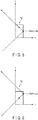
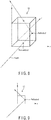
- FIG. 3 is a schematic diagram illustrating a state of light that is reflected twice by a single optical element 12.
- FIG. 4 is a diagram illustrating an optical path when the optical element 12 is viewed from the z direction.
- FIG. 5 is a diagram illustrating an optical path when the optical element 12 is viewed from the y direction.
- FIG. 6 is a diagram illustrating an optical path when the optical element 12 is viewed from the x direction.
- Light incident from a bottom surface of the optical element 12 is reflected by a first side surface, further reflected by a second side surface that is perpendicular to the first side surface, and then emitted from a top surface.
- the light incident on a given side surface of the optical element 12 not all the components of the light are reflected by that side surface, and the light is divided into a reflective component and a transmissive component.
- the reflective component is a component of light reflected by the side surface at an angle of reflection corresponding to the incident angle
- the transmissive component is a component of light that is linearly transmitted through the side surface.
- FIG. 7 is a schematic diagram illustrating a ghost 31 displayed by the aerial display apparatus.
- the ghost 31 is an image formed by light that is reflected only once (i.e., light that is not reflected twice) by the mirror device 10.
- the ghost 31 is formed at a position that is not plane-symmetrical to the display device 20 with respect to the mirror device 10.
- FIG. 8 is a schematic diagram illustrating a state of light reflected once by a single optical element 12.
- FIG. 9 is a diagram illustrating an optical path when the optical element 12 is viewed from the z direction.
- FIG. 10 is a diagram illustrating an optical path when the optical element 12 is viewed from the y direction.
- FIG. 11 is a diagram illustrating an optical path when the optical element 12 is viewed from the x direction.
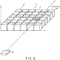
- FIG. 12 is a schematic diagram illustrating unwanted light 32 of the aerial display apparatus.
- the unwanted light 32 is light that is not reflected at all by the mirror device 10.
- the unwanted light 32 is linearly transmitted through the mirror device 10.
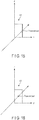
- FIG. 13 is a schematic diagram illustrating a state of light that is not reflected at all by a single optical element 12.
- FIG. 14 is a diagram illustrating an optical path when the optical element 12 is viewed from the z direction.
- FIG. 15 is a diagram illustrating an optical path when the optical element 12 is viewed from the y direction.
- FIG. 16 is a diagram illustrating an optical path when the optical element 12 is viewed from the x direction.
- the light incident from the bottom surface of the optical element 12 is not reflected by the first side surface, and is linearly transmitted through the first side surface.
- the unwanted light 32 brightens the periphery of the aerial image 30. Due to the unwanted light 32, the contrast of the aerial image 30 is reduced.
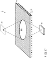
- FIG. 17 is a perspective view of the aerial display apparatus 1 according to the first embodiment.
- the aerial display apparatus 1 includes a mirror device 10, a display device 20, and a light shielding film (light shielding member) 40.
- a plurality of devices constituting the aerial display apparatus 1 are shown as if they are floating; however, these devices are fixed at the illustrated positions by unillustrated support members. The same applies to the subsequent drawings.
- the display device 20 includes a display surface, and displays an image on the display surface.
- the display surface of the display device 20 is disposed on the side of the mirror device 10.
- Various displays can be used as the display device 20; example configurations of the display device 20 include a liquid crystal display device, an organic electroluminescence (EL) display device, etc.
- the mirror device 10 is disposed at a distance from the display device 20. Upon receiving display light from the display device 20, the mirror device 10 reflects the display light toward an opposite side of the display device 20. Thereby, the mirror device 10 forms the aerial image 30 at a position that is plane-symmetrical to the display device 20.
- the size (area) of the mirror device 10 is set to be larger than an area capable of receiving display light for forming the aerial image 30, namely, with a margin from the area capable of receiving the display light.
- the mirror device 10 may be disposed in such a manner that the optical elements 12 face the display device 20, or the base member 11 faces the display device 20.
- FIG. 17 is a configuration example in which the optical elements 12 are disposed on the side of the display device 20, namely, a configuration example in which the mirror device 10 of FIG. 1 is disposed upside down.
- the light shielding film 40 is provided so as to be in contact with the mirror device 10.
- the light shielding film 40 is, for example, adhered to the mirror device 10.
- the light shielding film 40 may be provided on the side of the base member 11 of the mirror device 10, or on the side of the optical elements 12.
- the light shielding film 40 includes, at its center, an opening 40A.
- the opening 40A allows light that forms the aerial image 30 to pass through.
- the light shielding film 40 has a function of shielding the ghost and/or unwanted light.
- the light shielding film 40 is configured of, for example, a resin mixed with a black dye. Examples of the resin used for the light shielding film 40 include polyethylene terephthalate (PET).
- the opening 40A is, for example, a circle.
- the opening 40A is set to have an area that allows display light for forming the aerial image 30 to be transmitted therethrough, and allows ghosts and/or unwanted light to be shielded.
- the area of the opening 40A is appropriately set in accordance with the size (area) of the display screen of the display device 20, the distance between the display device 20 and the mirror device 10, and the positional relationship between the display device 20 and the mirror device 10.
- the area of the opening 40A is, for example, larger than the area of the display device 20.
- an aerial display apparatus 1 includes a display device 20 that displays an image, a mirror device 10 that reflects display light from the display device 20, and a light shielding film (light shielding member) 40 provided on the mirror device 10 on an opposite side of the display device 20.
- the mirror device 10 includes a plurality of optical elements 12 each including two reflective surfaces that are orthogonally disposed, and forms an aerial image 30 at a position that is plane-symmetrical to the display device 20.
- the light shielding film 40 includes an opening 40A that allows a portion of incident light to pass through, and shields light incident on a region other than the opening 40A.
- the aerial display apparatus 1 is capable of shielding light that forms a ghost, it is possible to prevent the ghost from being visually recognized by the observer. Further, since the aerial display apparatus 1 is capable of shielding unwanted light, the contrast of the aerial image 30 can be improved. As a result, it is possible to improve the display quality of the aerial display apparatus 1.
- a light shielding member for shielding ghosts and/or unwanted light is disposed at a distance from a mirror device 10.
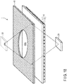
- FIG. 18 is a perspective view of an aerial display apparatus 1 according to the second embodiment.
- the aerial display apparatus 1 includes a mirror device 10, a display device 20, and a light shielding plate (light shielding member) 40.
- the light shielding plate 40 is disposed at a distance from the mirror device 10 on an opposite side of the display device 20 with respect to the mirror device 10.
- the light shielding plate 40 is configured of, for example, a resin mixed with a black dye.
- the light shielding plate 40 has a function of shielding the ghost and/or unwanted light.
- the light shielding plate 40 is capable of shielding a larger number of light components other than the light for forming the aerial image 30. It is thereby possible to shield ghosts and/or unwanted light.
- ghosts and/or unwanted light are shielded by using a light limiting device that allows only light which has an angle of emission that falls within a predetermined range to be transmitted therethrough.
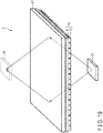
- FIG. 19 is a perspective view of an aerial display apparatus 1 according to the third embodiment.
- the aerial display apparatus 1 includes a mirror device 10, a display device 20, and a light limiting device 41.
- the light limiting device 41 is disposed on an opposite side of the display device 20 with respect to the mirror device 10.
- the light limiting device 41 may be disposed in contact with the mirror device 10, or at a distance from the mirror device 10.
- the light limiting device 41 has a function of allowing a light component of light incident thereon which has an angle of emission that falls within a predetermined range to be transmitted therethrough, and of shielding a light component of the incident light which has an angle of emission that falls outside the predetermined range. That is, the light limiting device 41 has a function of allowing display light for forming an aerial image 30 to be transmitted therethrough, and of shielding ghosts and/or unwanted light.
- FIG. 20 is a perspective view of the light limiting device 41.
- the light limiting device 41 includes a base member 42, a plurality of transmissive layers 43, and a plurality of light shielding layers 44.
- the transmissive layers 43 and the light shielding layers 44 are disposed in an alternating manner, and adjacent layers are in contact with each other.
- the transmissive layers 43 and the light shielding layers 44 are disposed side by side in the x direction, each extending in the y direction.
- the base member 42 and the transmissive layers 43 allow light to be transmitted therethrough.
- the base member 42 and the transmissive layers 43 are configured of a transparent resin.
- the light shielding layers 44 shield light.
- the light shielding layers 44 are configured of, for example, a resin mixed with a black dye.
- the angle of emission of the light limiting device 41 is set within a range equal to or greater than 0 degrees and equal to or smaller than 60 degrees on each of the right and left sides, with respect to the normal. More desirably, the angle of emission of the light limiting device 41 is set within a range equal to or greater than 0 degrees and equal to or smaller than 45 degrees on each of the right and left sides, with respect to the normal.
- the angle of emission is an angle from the normal of the light limiting device 41.
- the third embodiment it is possible to shield ghosts and/or unwanted light. Thereby, it is possible to improve the display quality of the aerial display apparatus 1.
- the light limiting device 41 may be disposed between the display device 20 and the mirror device 10. It may be disposed, for example, in contact with the mirror device 10 on the side of the display device 20. In the present embodiment, light that may become a ghost and/or unwanted light can be shielded before it enters the mirror device 10. Thereby, it is possible to improve the display quality of the aerial display apparatus 1.
- the light limiting device 41 shown in the third embodiment can be additionally applied to the configurations of the first and second embodiments.
- a liquid crystal display device is used as a display device.
- the light emitted from a back light is limited to a light component which has an angle of emission that falls within a predetermined range, using a light limiting device 41.
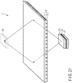
- FIG. 21 is a perspective view of an aerial display apparatus 1 according to the fourth embodiment.
- the aerial display apparatus 1 includes a mirror device 10, a liquid crystal display device (light modulating device) 20, a light source unit (back light) 21, and a light limiting device 41.
- the back light 21 produces illumination light and emits the illumination light toward the liquid crystal display device 20.
- the back light 21 is configured of a surface light source.
- the light limiting device 41 is disposed between the back light 21 and the liquid crystal display device 20.
- the light limiting device 41 has a function of allowing a light component of light incident thereon which has an angle of emission that falls within a predetermined range to be transmitted therethrough, and of shielding a light component of the incident light which has an angle of emission that falls outside the predetermined range. That is, the light limiting device 41 has a function of allowing illumination light for forming an aerial image 30 to be transmitted therethrough, and of shielding in advance illumination light that causes ghosts and/or unwanted light.
- the structure of the light limiting device 41 of FIG. 21 is the same as the light limiting device 41 of FIG. 20 , except for the difference in size.
- the liquid crystal display device 20 receives illumination light that is transmitted through the light limiting device 41.
- the liquid crystal display device 20 allows illumination light to be transmitted therethrough, and performs light modulation.
- the liquid crystal display device 20 displays a desired image on its display surface.
- a driving mode of the liquid crystal display device 20 is not particularly limited, and a twisted nematic (TN) mode, a vertical alignment (VA) mode, a homogeneous mode, or the like can be used.
- the fourth embodiment it is possible to shield the illumination light that causes ghosts and/or unwanted light at a stage before the display light enters the mirror device 10. Thereby, it is possible to improve the display quality of the aerial display apparatus 1.
- the light limiting device 41 may be disposed on an opposite side of the back light 21 with respect to the display device 20.
- the light limiting device 41 having substantially the same size as the display device 20 may be disposed in contact with or at a distance from the display surface of the display device 20.
- the light limiting device 41 may be disposed in contact with or at a distance from the display surface of the display device.
- the light limiting device 41 shown in the fourth embodiment can be additionally applied to the configurations of the first and second embodiments.
- a region of the mirror device 10 in which a plurality of optical elements 12 are disposed is reduced to a size capable of reflecting light that contributes to formation of an aerial image.
- the light that causes ghosts and/or unwanted light is suppressed from being diffused by the optical element 12.
- FIG. 22 is a perspective view of an aerial display apparatus 1 according to the fifth embodiment.
- the aerial display apparatus 1 includes a mirror device 10 and a display device 20.
- the mirror device 10 includes a base member 11 and a plurality of optical elements 12 provided on the base member 11.
- the optical elements 12 are disposed on the base member 11 on an opposite side of the display device 20 with respect to the base member 11.
- a plurality of optical elements 12 may be disposed so as to face the display device 20.
- a region in which the optical elements 12 are disposed is limited to a central portion of the base member 11.
- the region in which the optical elements 12 are disposed is reduced to a size capable of reflecting light that contributes to formation of an aerial image 30. Thereby, it is possible to suppress the display light emitted from the display device 20 from being diffused in a region other than the region in which the optical elements 12 are disposed. As a result, it is possible to improve the display quality of the aerial display apparatus 1.
- the mirror device 10 of the fifth embodiment can be applied to the first to fourth embodiments.
- the mirror device 10 is configured to include a plurality of optical elements 12 each having a rectangular parallelepiped shape.
- the structure of the mirror device 10 is not limited thereto.
- the mirror device 10 may be configured, for example, to include a plurality of holes in a transparent base member, each hole having two reflective surfaces that are orthogonally disposed.
- the mirror device 10 is configured in such a manner that a plurality of holes each having a square or rectangular planar shape are disposed in a matrix in a transparent base member.
- the optical element that reflects light twice may be either convex or concave.
- the present invention is not limited to the above-described embodiments, and can be modified in practice, without departing from the gist of the invention.
- the embodiments described above include inventions at various stages, and various inventions can be configured by an appropriate combination of a plurality of components disclosed in a single embodiment or an appropriate combination of components disclosed in different embodiments. For example, if the object of the invention is achieved and advantages of the invention are attained even after some of the structural elements are deleted from all the structural elements disclosed in the embodiment, the structure made up of the resultant structural elements may be extracted as an invention.
Landscapes
- Physics & Mathematics (AREA)
- General Physics & Mathematics (AREA)
- Optics & Photonics (AREA)
- Optical Elements Other Than Lenses (AREA)
- Testing, Inspecting, Measuring Of Stereoscopic Televisions And Televisions (AREA)
Abstract
Description
- The present invention relates to an aerial display apparatus.
- A dihedral corner reflector array has been proposed in which real mirror-image forming optical systems (dihedral corner reflectors) that form a real image of an observation target in a space of the observer side are disposed in an array as basic components to allow observation of a real image of an observation target formed in the air (see Patent Document 1). Consideration has been given to application of a display device that uses a mirror device such as a dihedral corner reflector array to a non-contact input device (button) in the fields of medicine and food, in combination with an infrared touch panel, as well as amusement.
-
- Patent Document 1: Jpn. Pat. Appln. KOKAI Publication No.
2017-67933 - Patent Document 2: International Publication No.
2009/136578 - The present invention provides an aerial display apparatus capable of improving the display quality of an aerial image.
- According to an aspect of the present invention, there is provided an aerial display apparatus comprising:
- a display device which displays an image;
- a mirror device which includes a plurality of optical elements each including two reflective surfaces that are orthogonally disposed, which reflects display light from the display device, and which forms an aerial image at a position that is plane-symmetrical to the display device; and
- a light shielding member which is disposed on an optical path between the display device and the aerial image, which includes an opening that allows a portion of incident light to pass through, and which shields light incident on a region other than the opening.
- According to an aspect of the present invention, there is provided an aerial display apparatus, comprising:
- a display device which displays an image;
- a mirror device which includes a plurality of optical elements each including two reflective surfaces that are orthogonally disposed, which reflects display light from the display device, and which forms an aerial image at a position that is plane-symmetrical to the display device; and
- a light limiting device which is disposed on an optical path between the display device and the aerial image, and which allows a light component of incident light having an angle of emission that falls within a predetermined range to be transmitted therethrough.
- According to the present invention, it is possible to provide an aerial display apparatus capable of improving the display quality of an aerial image.
-
-
FIG. 1 is a perspective view of a mirror device. -
FIG. 2 is a schematic diagram illustrating a principle of an aerial display apparatus. -
FIG. 3 is a schematic diagram illustrating a state of light that is reflected twice by a single optical element. -
FIG. 4 is a diagram illustrating an optical path when the optical element inFIG. 3 is viewed from the z direction. -
FIG. 5 is a diagram illustrating an optical path when the optical element inFIG. 3 is viewed from the y direction. -
FIG. 6 is a diagram illustrating an optical path when the optical element inFIG. 3 is viewed from the x direction. -
FIG. 7 is a schematic diagram illustrating a ghost displayed by the aerial display apparatus. -
FIG. 8 is a schematic diagram illustrating a state of light that is reflected once by a single optical element. -
FIG. 9 is a diagram illustrating an optical path when the optical element inFIG. 8 is viewed from the z direction. -
FIG. 10 is a diagram illustrating an optical path when the optical element inFIG. 8 is viewed from the y direction. -
FIG. 11 is a diagram illustrating an optical path when the optical element inFIG. 8 is viewed from the x direction. -
FIG. 12 is a schematic diagram illustrating unwanted light of the aerial display apparatus. -
FIG. 13 is a schematic diagram illustrating a state of light that is not reflected at all by a single optical element. -
FIG. 14 is a diagram illustrating an optical path when the optical element inFIG. 13 is viewed from the z direction. -
FIG. 15 is a diagram illustrating an optical path when the optical element inFIG. 13 is viewed from the y direction. -
FIG. 16 is a diagram illustrating an optical path when the optical element inFIG. 13 is viewed from the x direction. -
FIG. 17 is a perspective view of an aerial display apparatus according to a first embodiment. -
FIG. 18 is a perspective view of an aerial display apparatus according to a second embodiment. -
FIG. 19 is a perspective view of an aerial display apparatus according to a third embodiment. -
FIG. 20 is a perspective view of a light limiting device shown inFIG. 19 . -
FIG. 21 is a perspective view of an aerial display apparatus according to a fourth embodiment. -
FIG. 22 is a perspective view of an aerial display apparatus according to a fifth embodiment. - Hereinafter, embodiments will be described with reference to the drawings. The drawings are schematic or conceptual, and the dimensions, ratios, and the like of each drawing are not necessarily the same as the actual ones. Even when the same portions are shown in the drawings, the dimensional relationship and the ratio may be different. In particular, several embodiments described below exemplify an apparatus and a method for embodying the technical idea of the present invention, and the technical idea of the present invention is not specified by the shape, structure, arrangement, or the like of the components. In the following description, elements having the same function and configuration will be denoted by the same reference numerals, and redundant descriptions will be made only when necessary.
- An aerial display apparatus is configured, for example, to form an image of light emitted from a display surface of a liquid crystal display, using an aerial imaging device (mirror device) such as a dihedral corner reflector.
- A configuration of a
mirror device 10 used in an aerial display apparatus will be described.FIG. 1 is a perspective view of themirror device 10. - The
mirror device 10 includes aplanar base member 11 and a plurality ofoptical elements 12 provided on thebase member 11. Theoptical elements 12 are arranged, for example, in a matrix so as to extend in an x direction and a y direction that are orthogonal to each other. Each of theoptical elements 12 has two reflective surfaces that are orthogonally disposed. Eachoptical element 12 has a cubic or rectangular parallelepiped shape. Thebase member 11 and theoptical elements 12 are configured of a transparent resin. - In
FIG. 1 , 36 (= 6 × 6)optical elements 12 are shown as an example; however, in actuality, a greater number ofoptical elements 12 are disposed. The number and size of theoptical elements 12 can be freely set according to the specification of the aerial display apparatus. A distance between twooptical elements 12 can be freely set according to the specification of the aerial display apparatus. -
FIG. 2 is a schematic diagram illustrating the principle of the aerial display apparatus. The aerial display apparatus includes adisplay device 20 that displays an image on a display surface and amirror device 10. InFIG. 2 , thebase member 11 of themirror device 10 is not illustrated, and only theoptical elements 12 are extracted for illustration, for the ease of understanding of the drawing. Theoptical elements 12 are arranged on an x-y plane. The z direction is a height direction of theoptical elements 12. - Light (display light) emitted from the
display device 20 is reflected by two side surfaces of each of theoptical elements 12. InFIG. 2 , the optical path of light reflected by the hatchedoptical element 12 is extracted for illustration. The light emitted from thedisplay device 20 forms an image at a position that is plane-symmetrical to thedisplay device 20 with respect to themirror device 10, and anaerial image 30 is formed at that position. An observer can visually recognize the aerial image. -
FIG. 3 is a schematic diagram illustrating a state of light that is reflected twice by a singleoptical element 12.FIG. 4 is a diagram illustrating an optical path when theoptical element 12 is viewed from the z direction.FIG. 5 is a diagram illustrating an optical path when theoptical element 12 is viewed from the y direction.FIG. 6 is a diagram illustrating an optical path when theoptical element 12 is viewed from the x direction. - Light incident from a bottom surface of the
optical element 12 is reflected by a first side surface, further reflected by a second side surface that is perpendicular to the first side surface, and then emitted from a top surface. - It should be noted that for light incident on a given side surface of the
optical element 12, not all the components of the light are reflected by that side surface, and the light is divided into a reflective component and a transmissive component. The reflective component is a component of light reflected by the side surface at an angle of reflection corresponding to the incident angle, and the transmissive component is a component of light that is linearly transmitted through the side surface. - Next, a ghost that is formed at an unintended position will be described. A ghost is a double image that appears in the vicinity of the
aerial image 30.FIG. 7 is a schematic diagram illustrating aghost 31 displayed by the aerial display apparatus. - The
ghost 31 is an image formed by light that is reflected only once (i.e., light that is not reflected twice) by themirror device 10. Theghost 31 is formed at a position that is not plane-symmetrical to thedisplay device 20 with respect to themirror device 10. -
FIG. 8 is a schematic diagram illustrating a state of light reflected once by a singleoptical element 12.FIG. 9 is a diagram illustrating an optical path when theoptical element 12 is viewed from the z direction.FIG. 10 is a diagram illustrating an optical path when theoptical element 12 is viewed from the y direction.FIG. 11 is a diagram illustrating an optical path when theoptical element 12 is viewed from the x direction. - Light incident from a bottom surface of the
optical element 12 is reflected by a first side surface, and is then transmitted through a second side surface that is perpendicular to the first side surface. The light that travels along this path forms an image at a position that is not plane-symmetrical to thedisplay device 20 with respect to themirror device 10, thereby displaying aghost 31. (Regarding unwanted light) - Next, unwanted light will be described. Unwanted light is a light component that does not contribute to formation of a real image.
FIG. 12 is a schematic diagram illustratingunwanted light 32 of the aerial display apparatus. - The
unwanted light 32 is light that is not reflected at all by themirror device 10. Theunwanted light 32 is linearly transmitted through themirror device 10. -
FIG. 13 is a schematic diagram illustrating a state of light that is not reflected at all by a singleoptical element 12.FIG. 14 is a diagram illustrating an optical path when theoptical element 12 is viewed from the z direction.FIG. 15 is a diagram illustrating an optical path when theoptical element 12 is viewed from the y direction.FIG. 16 is a diagram illustrating an optical path when theoptical element 12 is viewed from the x direction. - The light incident from the bottom surface of the
optical element 12 is not reflected by the first side surface, and is linearly transmitted through the first side surface. - The
unwanted light 32 brightens the periphery of theaerial image 30. Due to theunwanted light 32, the contrast of theaerial image 30 is reduced. - Next, a configuration of an
aerial display apparatus 1 according to a first embodiment will be described.FIG. 17 is a perspective view of theaerial display apparatus 1 according to the first embodiment. - The
aerial display apparatus 1 includes amirror device 10, adisplay device 20, and a light shielding film (light shielding member) 40. InFIG. 17 , a plurality of devices constituting theaerial display apparatus 1 are shown as if they are floating; however, these devices are fixed at the illustrated positions by unillustrated support members. The same applies to the subsequent drawings. - The
display device 20 includes a display surface, and displays an image on the display surface. The display surface of thedisplay device 20 is disposed on the side of themirror device 10. Various displays can be used as thedisplay device 20; example configurations of thedisplay device 20 include a liquid crystal display device, an organic electroluminescence (EL) display device, etc. - The
mirror device 10 is disposed at a distance from thedisplay device 20. Upon receiving display light from thedisplay device 20, themirror device 10 reflects the display light toward an opposite side of thedisplay device 20. Thereby, themirror device 10 forms theaerial image 30 at a position that is plane-symmetrical to thedisplay device 20. The size (area) of themirror device 10 is set to be larger than an area capable of receiving display light for forming theaerial image 30, namely, with a margin from the area capable of receiving the display light. - The
mirror device 10 may be disposed in such a manner that theoptical elements 12 face thedisplay device 20, or thebase member 11 faces thedisplay device 20.FIG. 17 is a configuration example in which theoptical elements 12 are disposed on the side of thedisplay device 20, namely, a configuration example in which themirror device 10 ofFIG. 1 is disposed upside down. - The
light shielding film 40 is provided so as to be in contact with themirror device 10. Thelight shielding film 40 is, for example, adhered to themirror device 10. Thelight shielding film 40 may be provided on the side of thebase member 11 of themirror device 10, or on the side of theoptical elements 12. - The
light shielding film 40 includes, at its center, anopening 40A. Theopening 40A allows light that forms theaerial image 30 to pass through. Thelight shielding film 40 has a function of shielding the ghost and/or unwanted light. Thelight shielding film 40 is configured of, for example, a resin mixed with a black dye. Examples of the resin used for thelight shielding film 40 include polyethylene terephthalate (PET). - The
opening 40A is, for example, a circle. Theopening 40A is set to have an area that allows display light for forming theaerial image 30 to be transmitted therethrough, and allows ghosts and/or unwanted light to be shielded. The area of theopening 40A is appropriately set in accordance with the size (area) of the display screen of thedisplay device 20, the distance between thedisplay device 20 and themirror device 10, and the positional relationship between thedisplay device 20 and themirror device 10. The area of theopening 40A is, for example, larger than the area of thedisplay device 20. - As described in detail above, in the first embodiment, an
aerial display apparatus 1 includes adisplay device 20 that displays an image, amirror device 10 that reflects display light from thedisplay device 20, and a light shielding film (light shielding member) 40 provided on themirror device 10 on an opposite side of thedisplay device 20. Themirror device 10 includes a plurality ofoptical elements 12 each including two reflective surfaces that are orthogonally disposed, and forms anaerial image 30 at a position that is plane-symmetrical to thedisplay device 20. Thelight shielding film 40 includes anopening 40A that allows a portion of incident light to pass through, and shields light incident on a region other than theopening 40A. - According to the first embodiment, since the
aerial display apparatus 1 is capable of shielding light that forms a ghost, it is possible to prevent the ghost from being visually recognized by the observer. Further, since theaerial display apparatus 1 is capable of shielding unwanted light, the contrast of theaerial image 30 can be improved. As a result, it is possible to improve the display quality of theaerial display apparatus 1. - In a second embodiment, a light shielding member for shielding ghosts and/or unwanted light is disposed at a distance from a
mirror device 10. -
FIG. 18 is a perspective view of anaerial display apparatus 1 according to the second embodiment. Theaerial display apparatus 1 includes amirror device 10, adisplay device 20, and a light shielding plate (light shielding member) 40. - The
light shielding plate 40 is disposed at a distance from themirror device 10 on an opposite side of thedisplay device 20 with respect to themirror device 10. Thelight shielding plate 40 is configured of, for example, a resin mixed with a black dye. Thelight shielding plate 40 has a function of shielding the ghost and/or unwanted light. - According to the second embodiment, the
light shielding plate 40 is capable of shielding a larger number of light components other than the light for forming theaerial image 30. It is thereby possible to shield ghosts and/or unwanted light. - In a third embodiment, ghosts and/or unwanted light are shielded by using a light limiting device that allows only light which has an angle of emission that falls within a predetermined range to be transmitted therethrough.
-
FIG. 19 is a perspective view of anaerial display apparatus 1 according to the third embodiment. Theaerial display apparatus 1 includes amirror device 10, adisplay device 20, and a light limitingdevice 41. - The light limiting
device 41 is disposed on an opposite side of thedisplay device 20 with respect to themirror device 10. The light limitingdevice 41 may be disposed in contact with themirror device 10, or at a distance from themirror device 10. - The light limiting
device 41 has a function of allowing a light component of light incident thereon which has an angle of emission that falls within a predetermined range to be transmitted therethrough, and of shielding a light component of the incident light which has an angle of emission that falls outside the predetermined range. That is, thelight limiting device 41 has a function of allowing display light for forming anaerial image 30 to be transmitted therethrough, and of shielding ghosts and/or unwanted light. -
FIG. 20 is a perspective view of the light limitingdevice 41. The light limitingdevice 41 includes abase member 42, a plurality oftransmissive layers 43, and a plurality of light shielding layers 44. The transmissive layers 43 and the light shielding layers 44 are disposed in an alternating manner, and adjacent layers are in contact with each other. The transmissive layers 43 and the light shielding layers 44 are disposed side by side in the x direction, each extending in the y direction. Thebase member 42 and thetransmissive layers 43 allow light to be transmitted therethrough. Thebase member 42 and thetransmissive layers 43 are configured of a transparent resin. The light shielding layers 44 shield light. The light shielding layers 44 are configured of, for example, a resin mixed with a black dye. The angle of emission of the light limitingdevice 41 is set within a range equal to or greater than 0 degrees and equal to or smaller than 60 degrees on each of the right and left sides, with respect to the normal. More desirably, the angle of emission of the light limitingdevice 41 is set within a range equal to or greater than 0 degrees and equal to or smaller than 45 degrees on each of the right and left sides, with respect to the normal. The angle of emission is an angle from the normal of the light limitingdevice 41. - According to the third embodiment, it is possible to shield ghosts and/or unwanted light. Thereby, it is possible to improve the display quality of the
aerial display apparatus 1. - The light limiting
device 41 may be disposed between thedisplay device 20 and themirror device 10. It may be disposed, for example, in contact with themirror device 10 on the side of thedisplay device 20. In the present embodiment, light that may become a ghost and/or unwanted light can be shielded before it enters themirror device 10. Thereby, it is possible to improve the display quality of theaerial display apparatus 1. - Moreover, the
light limiting device 41 shown in the third embodiment can be additionally applied to the configurations of the first and second embodiments. - In the fourth embodiment, a liquid crystal display device is used as a display device. In addition, the light emitted from a back light is limited to a light component which has an angle of emission that falls within a predetermined range, using a
light limiting device 41. -
FIG. 21 is a perspective view of anaerial display apparatus 1 according to the fourth embodiment. Theaerial display apparatus 1 includes amirror device 10, a liquid crystal display device (light modulating device) 20, a light source unit (back light) 21, and a light limitingdevice 41. - The back light 21 produces illumination light and emits the illumination light toward the liquid
crystal display device 20. The back light 21 is configured of a surface light source. - The light limiting
device 41 is disposed between the back light 21 and the liquidcrystal display device 20. The light limitingdevice 41 has a function of allowing a light component of light incident thereon which has an angle of emission that falls within a predetermined range to be transmitted therethrough, and of shielding a light component of the incident light which has an angle of emission that falls outside the predetermined range. That is, thelight limiting device 41 has a function of allowing illumination light for forming anaerial image 30 to be transmitted therethrough, and of shielding in advance illumination light that causes ghosts and/or unwanted light. The structure of the light limitingdevice 41 ofFIG. 21 is the same as thelight limiting device 41 ofFIG. 20 , except for the difference in size. - The liquid
crystal display device 20 receives illumination light that is transmitted through the light limitingdevice 41. The liquidcrystal display device 20 allows illumination light to be transmitted therethrough, and performs light modulation. The liquidcrystal display device 20 displays a desired image on its display surface. A driving mode of the liquidcrystal display device 20 is not particularly limited, and a twisted nematic (TN) mode, a vertical alignment (VA) mode, a homogeneous mode, or the like can be used. - According to the fourth embodiment, it is possible to shield the illumination light that causes ghosts and/or unwanted light at a stage before the display light enters the
mirror device 10. Thereby, it is possible to improve the display quality of theaerial display apparatus 1. - The light limiting
device 41 may be disposed on an opposite side of the back light 21 with respect to thedisplay device 20. The light limitingdevice 41 having substantially the same size as thedisplay device 20 may be disposed in contact with or at a distance from the display surface of thedisplay device 20. - When a self-luminous display device such as an organic EL display device is used, the
light limiting device 41 may be disposed in contact with or at a distance from the display surface of the display device. - Moreover, the
light limiting device 41 shown in the fourth embodiment can be additionally applied to the configurations of the first and second embodiments. - In a fifth embodiment, a region of the
mirror device 10 in which a plurality ofoptical elements 12 are disposed is reduced to a size capable of reflecting light that contributes to formation of an aerial image. The light that causes ghosts and/or unwanted light is suppressed from being diffused by theoptical element 12. -
FIG. 22 is a perspective view of anaerial display apparatus 1 according to the fifth embodiment. Theaerial display apparatus 1 includes amirror device 10 and adisplay device 20. - The
mirror device 10 includes abase member 11 and a plurality ofoptical elements 12 provided on thebase member 11. In the example ofFIG. 22 , theoptical elements 12 are disposed on thebase member 11 on an opposite side of thedisplay device 20 with respect to thebase member 11. As a matter of course, a plurality ofoptical elements 12 may be disposed so as to face thedisplay device 20. - A region in which the
optical elements 12 are disposed is limited to a central portion of thebase member 11. The region in which theoptical elements 12 are disposed is reduced to a size capable of reflecting light that contributes to formation of anaerial image 30. Thereby, it is possible to suppress the display light emitted from thedisplay device 20 from being diffused in a region other than the region in which theoptical elements 12 are disposed. As a result, it is possible to improve the display quality of theaerial display apparatus 1. - The
mirror device 10 of the fifth embodiment can be applied to the first to fourth embodiments. - In each of the embodiments, the
mirror device 10 is configured to include a plurality ofoptical elements 12 each having a rectangular parallelepiped shape. The structure of themirror device 10 is not limited thereto. Themirror device 10 may be configured, for example, to include a plurality of holes in a transparent base member, each hole having two reflective surfaces that are orthogonally disposed. Specifically, themirror device 10 is configured in such a manner that a plurality of holes each having a square or rectangular planar shape are disposed in a matrix in a transparent base member. In other words, the optical element that reflects light twice may be either convex or concave. - The present invention is not limited to the above-described embodiments, and can be modified in practice, without departing from the gist of the invention. Furthermore, the embodiments described above include inventions at various stages, and various inventions can be configured by an appropriate combination of a plurality of components disclosed in a single embodiment or an appropriate combination of components disclosed in different embodiments. For example, if the object of the invention is achieved and advantages of the invention are attained even after some of the structural elements are deleted from all the structural elements disclosed in the embodiment, the structure made up of the resultant structural elements may be extracted as an invention.
Claims (12)
- An aerial display apparatus comprising:a display device which displays an image;a mirror device which includes a plurality of optical elements each including two reflective surfaces that are orthogonally disposed, which reflects display light from the display device, and which forms an aerial image at a position that is plane-symmetrical to the display device; anda light shielding member which is disposed on an optical path between the display device and the aerial image, which includes an opening that allows a portion of incident light to pass through, and which shields light incident on a region other than the opening.
- The aerial display apparatus according to claim 1, wherein the light shielding member is disposed on the mirror device on an opposite side of the display device with respect to the mirror device.
- The aerial display apparatus according to claim 1, wherein the light shielding member is disposed at a distance from the mirror device on an opposite side of the display device with respect to the mirror device.
- The aerial display apparatus according to claim 1, wherein the mirror device includes a transparent base member, and
the optical elements are arranged in a matrix on the base member. - The aerial display apparatus according to claim 4, wherein the light shielding member is provided on the base member.
- The aerial display apparatus according to claim 1, wherein the opening is a circle.
- An aerial display apparatus, comprising:a display device which displays an image;a mirror device which includes a plurality of optical elements each including two reflective surfaces that are orthogonally disposed, which reflects display light from the display device, and which forms an aerial image at a position that is plane-symmetrical to the display device; anda light limiting device which is disposed on an optical path between the display device and the aerial image, and which allows a light component of incident light having an angle of emission that falls within a predetermined range to be transmitted therethrough.
- The aerial display apparatus according to claim 7, wherein the light limiting device is disposed on an opposite side of the display device with respect to the mirror device.
- The aerial display apparatus according to claim 7, wherein the display device includes a light source unit that produces light and a light modulating device that modulates the light from the light source unit, and
the light limiting device is disposed between the light source unit and the light modulating device. - The aerial display apparatus according to claim 7, wherein the light limiting device includes a transparent base member, a plurality of transmissive layers that are transparent and that are provided on the base member, and a plurality of light shielding layers that are provided on the base member and that shield light, and
the transmissive layers and the light shielding layers, each extending in a first direction, are arranged in an alternating manner. - The aerial display apparatus according to claim 7, wherein the mirror device includes a transparent base member, and
the optical elements are arranged in a matrix on the base member. - The aerial display apparatus according to claim 1 or 7, wherein each of the optical elements is formed of a cubic or rectangular parallelepiped shape.
Applications Claiming Priority (2)
| Application Number | Priority Date | Filing Date | Title |
|---|---|---|---|
| JP2018083787A JP7238267B2 (en) | 2018-04-25 | 2018-04-25 | aerial display |
| PCT/JP2019/013796 WO2019208097A1 (en) | 2018-04-25 | 2019-03-28 | Aerial display device |
Publications (2)
| Publication Number | Publication Date |
|---|---|
| EP3786687A1 true EP3786687A1 (en) | 2021-03-03 |
| EP3786687A4 EP3786687A4 (en) | 2022-02-09 |
Family
ID=68293990
Family Applications (1)
| Application Number | Title | Priority Date | Filing Date |
|---|---|---|---|
| EP19792774.2A Pending EP3786687A4 (en) | 2018-04-25 | 2019-03-28 | OVERHEAD DISPLAY DEVICE |
Country Status (5)
| Country | Link |
|---|---|
| US (1) | US11947139B2 (en) |
| EP (1) | EP3786687A4 (en) |
| JP (1) | JP7238267B2 (en) |
| CN (1) | CN111989610A (en) |
| WO (1) | WO2019208097A1 (en) |
Families Citing this family (6)
| Publication number | Priority date | Publication date | Assignee | Title |
|---|---|---|---|---|
| EP4148467A4 (en) * | 2020-05-15 | 2023-11-01 | Samsung Electronics Co., Ltd. | REFLECTIVE STRUCTURE, REFLECTIVE STRUCTURE ARRAY INCLUDING SAME, AND FLOATING IMAGE DISPLAY DEVICE |
| WO2022264294A1 (en) * | 2021-06-16 | 2022-12-22 | 三菱電機株式会社 | Aerial image display device and aerial image display method |
| CN114637127A (en) * | 2022-02-24 | 2022-06-17 | 安徽省东超科技有限公司 | Visual field control device applied to optical imaging system and optical imaging system |
| JP2023142986A (en) * | 2022-03-25 | 2023-10-06 | 凸版印刷株式会社 | Optical elements for aerial display devices and aerial display devices |
| JP2024047999A (en) * | 2022-09-27 | 2024-04-08 | Toppanホールディングス株式会社 | Aerial Display Device |
| JP2025083681A (en) * | 2023-11-21 | 2025-06-02 | アルプスアルパイン株式会社 | display device |
Family Cites Families (19)
| Publication number | Priority date | Publication date | Assignee | Title |
|---|---|---|---|---|
| US6064423A (en) * | 1998-02-12 | 2000-05-16 | Geng; Zheng Jason | Method and apparatus for high resolution three dimensional display |
| JP2001215444A (en) * | 2000-02-02 | 2001-08-10 | Konica Corp | Three-dimensional image display device |
| JP3818857B2 (en) * | 2001-02-07 | 2006-09-06 | シャープ株式会社 | Display device |
| US8985774B2 (en) * | 2007-03-30 | 2015-03-24 | National Institute Of Information And Communication Technology | Floating image interaction device and its program |
| WO2009136578A1 (en) | 2008-05-09 | 2009-11-12 | パイオニア株式会社 | Spatial image display apparatus |
| JP5665053B2 (en) * | 2011-02-04 | 2015-02-04 | 独立行政法人情報通信研究機構 | Multi-viewpoint aerial image display device |
| JP2013257529A (en) * | 2012-05-18 | 2013-12-26 | Sharp Corp | Optical system |
| JP5992302B2 (en) * | 2012-11-27 | 2016-09-14 | 日東電工株式会社 | Display device |
| JP5997606B2 (en) * | 2012-12-26 | 2016-09-28 | 日東電工株式会社 | Display device |
| US9097849B2 (en) * | 2013-03-07 | 2015-08-04 | Seiko Epson Corporation | Display device |
| JP2015166845A (en) * | 2014-02-13 | 2015-09-24 | 日本電気硝子株式会社 | Optical image forming element and method of manufacturing the same |
| CN107111149A (en) | 2014-12-01 | 2017-08-29 | Sn合伙合同会社 | Aerial picture display device |
| JP6583954B2 (en) * | 2015-01-08 | 2019-10-02 | 日東電工株式会社 | Exhibition apparatus and video display method |
| CN107850701B (en) * | 2015-07-27 | 2021-07-16 | 索尼公司 | Optical Devices and Display Units |
| JP6598297B2 (en) | 2015-09-29 | 2019-10-30 | 株式会社パリティ・イノベーションズ | 2-sided corner reflector array |
| JPWO2017125984A1 (en) * | 2016-01-21 | 2018-06-14 | パナソニックIpマネジメント株式会社 | Aerial display device |
| JP6944761B2 (en) * | 2016-02-01 | 2021-10-06 | 大日本印刷株式会社 | Space floating image display Optical sheet, space floating image display device |
| US10386648B2 (en) * | 2016-08-08 | 2019-08-20 | Innolux Corporation | Image display system |
| JP7087368B2 (en) * | 2017-12-13 | 2022-06-21 | 船井電機株式会社 | Aerial image display device |
-
2018
- 2018-04-25 JP JP2018083787A patent/JP7238267B2/en active Active
-
2019
- 2019-03-28 CN CN201980026667.XA patent/CN111989610A/en active Pending
- 2019-03-28 EP EP19792774.2A patent/EP3786687A4/en active Pending
- 2019-03-28 WO PCT/JP2019/013796 patent/WO2019208097A1/en not_active Ceased
-
2020
- 2020-10-23 US US17/079,321 patent/US11947139B2/en active Active
Also Published As
| Publication number | Publication date |
|---|---|
| CN111989610A (en) | 2020-11-24 |
| EP3786687A4 (en) | 2022-02-09 |
| JP7238267B2 (en) | 2023-03-14 |
| US20210041719A1 (en) | 2021-02-11 |
| JP2019191355A (en) | 2019-10-31 |
| US11947139B2 (en) | 2024-04-02 |
| WO2019208097A1 (en) | 2019-10-31 |
Similar Documents
| Publication | Publication Date | Title |
|---|---|---|
| US11947139B2 (en) | Aerial display apparatus | |
| US12517372B2 (en) | Aerial display apparatus | |
| US8403502B2 (en) | Collimated visual display with elliptical front projection screen | |
| JP2019219668A (en) | Color inorganic led display for display devices with high number of pixels | |
| US9523859B2 (en) | Volumetric-image forming system and method thereof | |
| KR20150112805A (en) | Spatial image display apparatus | |
| JP2013257529A (en) | Optical system | |
| JP2013182121A (en) | Display device | |
| US20180356643A1 (en) | Spatial image display apparatus and spatial image display method | |
| JP2019032404A (en) | Aerial video display device | |
| US9638991B2 (en) | Projection device capable of collecting light densely | |
| EP4502711A1 (en) | Optical element for aerial display device, and aerial display device | |
| US10935844B2 (en) | Light source, backlight module, display device, and electronic device | |
| JP5532815B2 (en) | Lighting device, projector and electronic device | |
| JP2022530167A (en) | Multi-view display and method with shifted color subpixels | |
| CN103376626B (en) | Projection device | |
| CN111796477B (en) | A high-resolution projection display device | |
| US11846851B2 (en) | Display panel, method for manufacturing same, and display device | |
| TW202309556A (en) | Optical element for aerial display device, and aerial display device | |
| US20250004297A1 (en) | Display device | |
| EP4535067A1 (en) | Aerial display device | |
| US20260023261A1 (en) | Display device | |
| US20260118563A1 (en) | Prism array panel capable of homoaxial imaging | |
| US20260099062A1 (en) | Display apparatus | |
| US20250370275A1 (en) | Air floating video display apparatus |
Legal Events
| Date | Code | Title | Description |
|---|---|---|---|
| STAA | Information on the status of an ep patent application or granted ep patent |
Free format text: STATUS: THE INTERNATIONAL PUBLICATION HAS BEEN MADE |
|
| PUAI | Public reference made under article 153(3) epc to a published international application that has entered the european phase |
Free format text: ORIGINAL CODE: 0009012 |
|
| STAA | Information on the status of an ep patent application or granted ep patent |
Free format text: STATUS: REQUEST FOR EXAMINATION WAS MADE |
|
| 17P | Request for examination filed |
Effective date: 20201105 |
|
| AK | Designated contracting states |
Kind code of ref document: A1 Designated state(s): AL AT BE BG CH CY CZ DE DK EE ES FI FR GB GR HR HU IE IS IT LI LT LU LV MC MK MT NL NO PL PT RO RS SE SI SK SM TR |
|
| AX | Request for extension of the european patent |
Extension state: BA ME |
|
| DAV | Request for validation of the european patent (deleted) | ||
| DAX | Request for extension of the european patent (deleted) | ||
| REG | Reference to a national code |
Ref country code: DE Ref legal event code: R079 Free format text: PREVIOUS MAIN CLASS: G02B0027220000 Ipc: G02B0030560000 |
|
| A4 | Supplementary search report drawn up and despatched |
Effective date: 20220112 |
|
| RIC1 | Information provided on ipc code assigned before grant |
Ipc: H04N 13/302 20180101ALI20220105BHEP Ipc: G02B 27/00 20060101ALI20220105BHEP Ipc: G02B 5/136 20060101ALI20220105BHEP Ipc: G02B 5/00 20060101ALI20220105BHEP Ipc: G02B 30/60 20200101ALI20220105BHEP Ipc: G02B 30/56 20200101AFI20220105BHEP |
|
| STAA | Information on the status of an ep patent application or granted ep patent |
Free format text: STATUS: EXAMINATION IS IN PROGRESS |
|
| 17Q | First examination report despatched |
Effective date: 20240216 |