EP3786675A2 - Process for extending operating temperature range of gigabit plastic optical fiber - Google Patents
Process for extending operating temperature range of gigabit plastic optical fiber Download PDFInfo
- Publication number
- EP3786675A2 EP3786675A2 EP20188923.5A EP20188923A EP3786675A2 EP 3786675 A2 EP3786675 A2 EP 3786675A2 EP 20188923 A EP20188923 A EP 20188923A EP 3786675 A2 EP3786675 A2 EP 3786675A2
- Authority
- EP
- European Patent Office
- Prior art keywords
- optical fiber
- plastic optical
- temperature
- transceiver
- gbpof
- Prior art date
- Legal status (The legal status is an assumption and is not a legal conclusion. Google has not performed a legal analysis and makes no representation as to the accuracy of the status listed.)
- Granted
Links
Images



Classifications
-
- H—ELECTRICITY
- H04—ELECTRIC COMMUNICATION TECHNIQUE
- H04B—TRANSMISSION
- H04B10/00—Transmission systems employing electromagnetic waves other than radio-waves, e.g. infrared, visible or ultraviolet light, or employing corpuscular radiation, e.g. quantum communication
- H04B10/25—Arrangements specific to fibre transmission
- H04B10/2589—Bidirectional transmission
- H04B10/25891—Transmission components
-
- G—PHYSICS
- G02—OPTICS
- G02B—OPTICAL ELEMENTS, SYSTEMS OR APPARATUS
- G02B6/00—Light guides; Structural details of arrangements comprising light guides and other optical elements, e.g. couplings
- G02B6/02—Optical fibres with cladding with or without a coating
- G02B6/02033—Core or cladding made from organic material, e.g. polymeric material
- G02B6/02038—Core or cladding made from organic material, e.g. polymeric material with core or cladding having graded refractive index
-
- B—PERFORMING OPERATIONS; TRANSPORTING
- B29—WORKING OF PLASTICS; WORKING OF SUBSTANCES IN A PLASTIC STATE IN GENERAL
- B29C—SHAPING OR JOINING OF PLASTICS; SHAPING OF MATERIAL IN A PLASTIC STATE, NOT OTHERWISE PROVIDED FOR; AFTER-TREATMENT OF THE SHAPED PRODUCTS, e.g. REPAIRING
- B29C35/00—Heating, cooling or curing, e.g. crosslinking or vulcanising; Apparatus therefor
- B29C35/02—Heating or curing, e.g. crosslinking or vulcanizing during moulding, e.g. in a mould
-
- B—PERFORMING OPERATIONS; TRANSPORTING
- B29—WORKING OF PLASTICS; WORKING OF SUBSTANCES IN A PLASTIC STATE IN GENERAL
- B29C—SHAPING OR JOINING OF PLASTICS; SHAPING OF MATERIAL IN A PLASTIC STATE, NOT OTHERWISE PROVIDED FOR; AFTER-TREATMENT OF THE SHAPED PRODUCTS, e.g. REPAIRING
- B29C71/00—After-treatment of articles without altering their shape; Apparatus therefor
- B29C71/02—Thermal after-treatment
-
- B—PERFORMING OPERATIONS; TRANSPORTING
- B29—WORKING OF PLASTICS; WORKING OF SUBSTANCES IN A PLASTIC STATE IN GENERAL
- B29D—PRODUCING PARTICULAR ARTICLES FROM PLASTICS OR FROM SUBSTANCES IN A PLASTIC STATE
- B29D11/00—Producing optical elements, e.g. lenses or prisms
- B29D11/00663—Production of light guides
- B29D11/00711—Production of light guides by shrinking the sleeve or cladding onto the core
-
- B—PERFORMING OPERATIONS; TRANSPORTING
- B64—AIRCRAFT; AVIATION; COSMONAUTICS
- B64F—GROUND OR AIRCRAFT-CARRIER-DECK INSTALLATIONS SPECIALLY ADAPTED FOR USE IN CONNECTION WITH AIRCRAFT; DESIGNING, MANUFACTURING, ASSEMBLING, CLEANING, MAINTAINING OR REPAIRING AIRCRAFT, NOT OTHERWISE PROVIDED FOR; HANDLING, TRANSPORTING, TESTING OR INSPECTING AIRCRAFT COMPONENTS, NOT OTHERWISE PROVIDED FOR
- B64F5/00—Designing, manufacturing, assembling, cleaning, maintaining or repairing aircraft, not otherwise provided for; Handling, transporting, testing or inspecting aircraft components, not otherwise provided for
- B64F5/10—Manufacturing or assembling aircraft, e.g. jigs therefor
-
- G—PHYSICS
- G02—OPTICS
- G02B—OPTICAL ELEMENTS, SYSTEMS OR APPARATUS
- G02B1/00—Optical elements characterised by the material of which they are made; Optical coatings for optical elements
- G02B1/04—Optical elements characterised by the material of which they are made; Optical coatings for optical elements made of organic materials, e.g. plastics
- G02B1/045—Light guides
- G02B1/046—Light guides characterised by the core material
-
- G—PHYSICS
- G02—OPTICS
- G02B—OPTICAL ELEMENTS, SYSTEMS OR APPARATUS
- G02B1/00—Optical elements characterised by the material of which they are made; Optical coatings for optical elements
- G02B1/04—Optical elements characterised by the material of which they are made; Optical coatings for optical elements made of organic materials, e.g. plastics
- G02B1/045—Light guides
- G02B1/048—Light guides characterised by the cladding material
-
- G—PHYSICS
- G02—OPTICS
- G02B—OPTICAL ELEMENTS, SYSTEMS OR APPARATUS
- G02B6/00—Light guides; Structural details of arrangements comprising light guides and other optical elements, e.g. couplings
- G02B6/24—Coupling light guides
- G02B6/42—Coupling light guides with opto-electronic elements
- G02B6/4201—Packages, e.g. shape, construction, internal or external details
- G02B6/4246—Bidirectionally operating package structures
-
- H—ELECTRICITY
- H04—ELECTRIC COMMUNICATION TECHNIQUE
- H04B—TRANSMISSION
- H04B10/00—Transmission systems employing electromagnetic waves other than radio-waves, e.g. infrared, visible or ultraviolet light, or employing corpuscular radiation, e.g. quantum communication
- H04B10/40—Transceivers
-
- H—ELECTRICITY
- H04—ELECTRIC COMMUNICATION TECHNIQUE
- H04B—TRANSMISSION
- H04B10/00—Transmission systems employing electromagnetic waves other than radio-waves, e.g. infrared, visible or ultraviolet light, or employing corpuscular radiation, e.g. quantum communication
- H04B10/50—Transmitters
- H04B10/501—Structural aspects
- H04B10/503—Laser transmitters
-
- B—PERFORMING OPERATIONS; TRANSPORTING
- B29—WORKING OF PLASTICS; WORKING OF SUBSTANCES IN A PLASTIC STATE IN GENERAL
- B29D—PRODUCING PARTICULAR ARTICLES FROM PLASTICS OR FROM SUBSTANCES IN A PLASTIC STATE
- B29D11/00—Producing optical elements, e.g. lenses or prisms
- B29D11/00663—Production of light guides
Definitions
- the technology disclosed herein generally relates to fiber optical networks that enable communication between electrical components.
- An optical fiber is a cylindrical dielectric waveguide that transmits light along its axis.
- the fiber consists of a transparent core surrounded by a transparent cladding layer (hereinafter "cladding"), both of which are made of dielectric materials.
- cladding transparent cladding layer
- Light is kept in the core by the phenomenon of total internal reflection.
- the refractive index of the core is greater than that of the cladding.
- the boundary between the core and cladding may either be abrupt, as in step-index fiber, or gradual, as in graded-index fiber.
- Optical fibers can be made of glass or plastic.
- a plastic optical fiber capable of transmitting data at rates faster than 1 gigabits per second will be referred to herein as a "gigabit plastic optical fiber" (GbPOF).
- GbPOF gigabit plastic optical fiber
- Gigabit plastic optical fiber has a core and cladding made of transparent carbon-hydrogen bond-free perfluorinated polymer. The perfluorinated polymer is ductile and does not break during tight cable bending.
- Commercially available examples of GbPOF have core diameters of 50 ⁇ 5, 62.5 ⁇ 5 and 120 ⁇ 5 microns and a cladding diameter of 490 ⁇ 10 microns.
- a multi-mode GbPOF with the same core diameter is more imperfect with long random polymer chains in spaghetti shapes. These polymer chains create strong forward mode coupling and result in less reflected light that can interfere with the laser source.
- the strong mode coupling in a GbPOF core also reduces the coherency of the laser source and results in minimal modal interference along the fiber length
- the avionics systems will include robust GbPOF for high-data-rate networks. But existing commercially available GbPOF can operate only up to 70 degrees Celsius, which is not suitable for use in avionics systems which operate at a temperature of 100 degrees Celsius.
- One existing solution is to use multi-mode glass optical fiber.
- the drawbacks of using multi-mode glass optical fiber include the following:
- a process capable of extending the operating temperature range of existing commercially available GbPOF would be useful in the manufacture of high-data-rate fiber optical networks.
- the subject matter disclosed in some detail below is directed to a process to enhance the performance of plastic optical fiber to operate with a high data rate (e.g., at least 1 gigabit per second) at high temperature (e.g., 100°C) for airplane avionic systems.
- Gigabit plastic optical fiber has a core including a dopant that enables data transmission at gigabit rates within an operating temperature range.
- the enhancement process proposed herein uses thermal cooling of the gigabit plastic optical fiber to stabilize the polymer matrix of the fiber. This rapid cooling treatment blocks dopant diffusion in a high-temperature environment, thereby avoiding degradation of the fiber's optical transmission characteristic (e.g., unacceptable increase in the optical loss characteristic and bandwidth reduction of the fiber). Stabilizing the dopant's distribution inside the GbPOF by a thermal cooling process enables the GbPOF to operate with a high data rate at up to 100°C.
- One aspect of the subject matter disclosed in detail below is a process for extending the operating temperature range of plastic optical fiber, the method comprising: (a) placing a length of plastic optical fiber, for example a length in the form of a loop, inside a thermal chamber, which plastic optical fiber has a core with dopant distributed in a polymer matrix such that the plastic optical fiber has a high-data-rate capability at a first temperature but not at a second temperature which is higher than the first temperature; (b) decreasing a temperature inside the thermal chamber until a third temperature lower than the first temperature is reached; (c) maintaining the third temperature inside the thermal chamber for a first period of time sufficient to cause the plastic optical fiber to develop the high-data-rate capability at the second temperature; (d) increasing the temperature inside the thermal chamber until a fourth temperature lower than the first temperature and higher than the third temperature is reached; (e) maintaining the fourth temperature inside the thermal chamber during a second period of time subsequent to the first period of time; and (f) removing the loop of plastic optical fiber from the thermal chamber.
- the second temperature can be 100 degrees Celsius
- the third temperature can be in a range of -55°C to -65°C
- the fourth temperature can be room temperature.
- room temperature means 20°C to 25°C.
- the plastic optical fiber is preferably a graded-index plastic optical fiber having a core and a cladding made of a transparent carbon-hydrogen bond-free perfluorinated polymer. Prior to the cooling treatment, the plastic optical fiber does not have a data rate capability of at least 10 gigabits per second at 100°C. Following the cooling treatment, the plastic optical fiber has a data rate capability of at least 10 gigabits per second at 100°C.
- opposing ends of the length of plastic optical fiber can be placed outside the thermal chamber.
- the process may further comprise: (g) optically coupling an optical transceiver to the opposing ends of the plastic optical fiber; and (h) electrically coupling a bit- error-rate tester to the optical transceiver, wherein steps (g) and (h) are performed after step (a) and before step (b).
- the process can further co: (i) testing the bit error rate of the plastic optical fiber at the high data rate.
- Step (i) may be performed twice: after step (h) and before step (b) and after step (e) and before step (f).
- a further aspect of the subject matter disclosed in detail below is a data transmission system comprising: an optical cable comprising a plastic optical fiber having first and second ends; a first transceiver optically coupled to the first end of the plastic optical fiber, the first transceiver comprising a laser disposed to transmit light into the plastic optical filter; a first electrical device configured for sending electrical signals representing data, the first electrical device being electrically coupled to the first transceiver; a second transceiver optically coupled to the second end of the plastic optical fiber, the second transceiver comprising a photodetector disposed to receive light from the plastic optical filter; a second electrical device configured for receiving electrical signals representing data, the second electrical device being electrically coupled to the second transceiver, wherein the plastic optical fiber has a data rate capability of at least 10 gigabits per second at 100°C.
- the plastic optical fiber is graded-index plastic optical fiber having a core and a cladding made of a transparent carbon-hydrogen bond-free perfluorinated polymer.
- the first and second electrical devices are line replaceable units of an avionics network system onboard an airplane.
- the disclosure is concerned with a process for extending the operating temperature range of plastic optical fiber, the method comprising:
- the fourth temperature can be room temperature; the second temperature can be 100 degrees Celsius; the third temperature can be in a range of -55 to -65 degrees Celsius.
- the plastic optical fiber can be graded-index plastic optical fiber having a core and a cladding made of a transparent carbon-hydrogen bond-free perfluorinated polymer.
- the plastic optical fiber can have a data rate capability up to 10 gigabits per second at 100 degrees Celsius.
- the plastic optical fiber can be installed in an avionics network system onboard an aircraft.
- the disclosure is concerned with a process for extending the operating temperature range of plastic optical fiber, the method comprising:
- An optical transceiver (2) can be optically coupled to the opposing ends of the plastic optical fiber (g); and a bit-error-rate tester (28) can be electrically coupled to the optical transceiver (h), wherein steps (g) and (h) are preferably performed after step (a) and before step (b).
- the bit error rate of the plastic optical fiber can be tested at a high data rate (i).
- Step (i) is can be performed after step (h) and before step (b) or step (i) can be performed after step (e) and before step (f).
- the second temperature can be 100 degrees Celsius.
- the third temperature can be in a range of -55 to -65 degrees Celsius.
- the plastic optical fiber can be graded-index plastic optical fiber having a core and a cladding made of a transparent carbon-hydrogen bond-free perfluorinated polymer.
- the plastic optical fiber can have a data rate capability up to 10 gigabits per second at 100 degrees Celsius.
- the plastic optical fiber can be installed in an avionics network system onboard an aircraft after step (f).
- a data transmission system comprising:
- the plastic optical fiber can be graded-index plastic optical fiber having a core and a cladding made of a transparent carbon-hydrogen bond-free perfluorinated polymer.
- the first and second electrical devices can be line replaceable units of an avionics network system onboard an airplane.
- the plastic optical fiber can be treated by cooling at a temperature in a range of -55 to -65 degrees Celsius prior to being optically coupled to the first and second transceivers.
- fiber optical network for enabling optical communication between line replaceable units on an airplane at high data transmission rates (e.g., greater than 1 Gbit/sec) will be described in detail below for the purpose of illustration.
- implementation of the fiber optical networks disclosed herein is not limited solely to the environment of an airplane, but rather may be utilized in fiber optical networks onboard other types of vehicles or other types of fiber optical networks (e.g., long-distance terrestrial, data center and fiber-to-the-home/office applications).
- FIG. 1 is a structural formula showing the chemical composition of one commercially available transparent carbon-hydrogen bond-free perfluorinated polymer. This graphic representation of the molecular structure shows how the atoms are possibly arranged in the real three-dimensional space. The chemical bonding within the molecule is also shown. The letter “n” indicates that the molecule is a repeating unit in a chain.
- the perfluorinated polymer depicted in FIG. 1 has fluorine atoms bonded to the carbon atoms instead of having hydrogen atoms bonded to the carbon atoms.
- An optical fiber having a core and cladding made of perfluorinated polymer enables higher data rates when used in large-capacity communications systems.
- GbPOF is made of long chains of polymers with dopant mixed in the polymer chains.
- the polymers of the GbPOF are chemically bonded, but the dopant is not chemically bonded to the polymers.
- FIG. 2 the diagram represents the structure of a GbPOF consisting of a doped polymer matrix 40.
- the repeating subunits of the linear polymer chains 42 are represented by dark-shaded circles, while the distribution of dopant molecules 44 is represented by light-shaded circles.
- the dopant molecules are impurities intentionally introduced to the GbPOF polymer chains during the GbPOF fabrication process. Dopant distribution in the host polymers can be altered by high temperature. This is the well-known "impurity diffusion" process, which drives the impurity from a high-density region to a lower-density region.
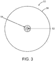
- FIG. 3 is a diagram representing a sectional view of a graded-index GbPOF 50 consisting of a core 52, a cladding 54 surrounding the core 52, and an over-cladding 56 surrounding the cladding 54.
- the core 52 and cladding 54 are made of the same transparent carbon-hydrogen bond-free perfluorinated polymer material; the over-cladding 56 is made of a polymeric material.
- What enables the graded-index GbPOF 50 to operate at high data rates is the dopant that is distributed in the center of the core of the GbPOF with a gradient (or Gaussian) index profile as indicated by shading in FIG. 3 .
- this gradient index profile is altered or degraded, the bandwidth of the GbPOF will change and the GbPOF will not be able to support the high data rate operation.
- graded-index GbPOF 50 a high-dopant-density region is located at the center of the core 52 (indicated by dark shading); the low-dopant-density region is located in the outer core region (indicated by light shading).
- the dopant diffusion process is enhanced by high temperature. This is the primary reason why one supplier limits the operation of a commercially available GbPOF to 70°C.
- This dopant-out diffusion process is enhanced by the thermal activity of the polymer chains in the host GbPOF. If the thermal activity of the polymer chains is reduced, then the redistribution of the dopant is reduced.
- This disclosure proposes a process for treating the GbPOF to stabilize or "lock-in" the distribution of dopant in the optical polymer matrix of the core 52 by rapid cooling.
- Experiments were performed which demonstrated that the rapid cooling process proposed herein enables the commercially available GbPOF to operate with a bandwidth up to 10 Gbits/sec at a temperature of 100°C. More specifically, experiments were performed to determine the effects of exposing a commercially available GbPOF to a temperature of 100°C for 24 hours. The experimental findings showed that the transparency of the commercially available GbPOF was not adversely affected by extended exposure to a temperature of 100°C, but the bandwidth was adversely affected by extended exposure to a temperature of 100°C.
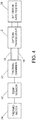
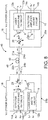
- FIG. 4 is a block diagram identifying components of an experimental set-up for rapid cooling of loops of GbPOF.
- the experimental set-up includes a thermal chamber 30, a temperature sensor 32 (e.g., a thermocouple) which is thermally coupled to the inside the thermal chamber 30, and a thermometer 34 which is electrically coupled to the temperature sensor 32.
- the temperature sensor 32 outputs an electrical signal that is a measure of the temperature inside the thermal chamber 30.
- a thermocouple produces a temperature-dependent voltage as a result of the thermoelectric effect.
- the thermometer 34 converts this temperature-dependent voltage into a numerical value that is displayed on a display screen.
- a host computing system (not shown in FIG. 4 ) is in communication with a data system by which a technician can download various parameters and profiles.
- the downloaded parameters include a desired setpoint chamber temperature at which to operate the thermal chamber 30 during the rapid cooling process disclosed herein.
- a processor runs software that implements a dual-loop feedback control system based on temperatures measured in the thermal chamber 30.
- the experimental design was to treat three loops of graded-index GbPOF differently and then measure the respective properties of the loops to determine the differences attributable to the treatment process used. As depicted in FIG. 4 , each loop of GbPOF 18 was placed inside the thermal chamber 30, but the respective ends of the GbPOF 18 were passed through the wall of and located exterior to the thermal chamber 30.
- the experimental set-up further includes an optical transceiver 2 capable of transmitting and receiving data at a rate of at least one gigabit per second and a bit-error-rate tester 28 which is electrically coupled to the optical transceiver 2.
- the ends of the GbPOF 18 are optically coupled to the optical transceiver 2.
- the optical transceiver 2 transmitted and received data at a rate of 10 gigabits per second via the GbPOF 18.
- the temperature inside the thermal chamber 30 was controlled to be close to if not exactly equal to a specified target temperature to which the loop of GbPOF 18 inside the thermal chamber 30 was exposed.
- the actual temperature inside the thermal chamber 30 was measured by the temperature sensor 32 and displayed by the thermometer 34.
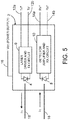
- FIG. 5 is a diagram identifying some components of a dual-fiber bidirectional optical transceiver 2 (hereinafter "optical transceiver") suitable for use in an experimental set-up of the type described herein.
- the optical transceiver 2 transmits and receives light of the same wavelength.
- the term "wavelength" in the context of coherent laser light means the center wavelength of laser light having a narrow bandwidth.
- the optical transceiver 2 includes a laser 4 and a photodetector 8.
- the laser 4 is optically coupled to one end of the GbPOF 18, while the photodetector 8 is optically coupled to the other end of the GbPOF 18.
- the laser 4 is driven to emit light of a wavelength ⁇ 1 by a laser driver and transmit circuit 6 in response to receipt of differential transmit signals Tx + and Tx - from the bit-error-rate tester 28 (not shown in FIG. 5 ) via transmit electrical signal lines 12a and 12b respectively.
- the laser driver and transmit circuit 6 comprises electrical circuitry that converts those electrical differential signals to electrical digital signals representing the data to be transmitted by the laser 4.
- the photodetector 8 receives light of wavelength ⁇ 1 and converts that detected light into electrical digital signals which are provided to a detector amplifier and receive circuit 10.
- the detector amplifier and receive circuit 10 in turn comprises electrical circuitry that converts those electrical digital signals to electrical differential receive signals Rx + and Rx - representing the data received.
- the electrical differential receive signals Rx + and Rx - are transmitted to the bit-error-rate tester 28 via receive electrical signal lines 14a and 14b respectively.
- the single-wavelength dual-fiber bidirectional transceiver 2 receives electrical power having a voltage V cc via transceiver power supply line 16.
- Loop #2 had the best high-data-rate (up to 10 Gbits/sec) performance after more than 24 hours of 100°C heating.
- Loop #2 also showed the best confinement of the optical signal to the center of the fiber core according to the near-field measurement results, which indicates that the dopant concentration profile is better maintained in Loop #2 than in the other two loops after the extended 100°C heating process.
- These experimental results are consistent with the theory (described above) that if the distribution of the gradient index profile is altered or degraded, the bandwidth of the GbPOF will change and will not be able to support high-data-rate operation.
- Loops #1 and #2 were both rapidly cooled, but Loop #2 had no optical injection during the cooling process, which indicates that the carbon-hydrogen bond-free perfluorinated polymer is more stable without the optical excitation during the rapid thermal "lock-in" process.
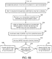
- FIGS. 6A and 6B are respective portions of a flowchart identifying steps of a process 100 for extending the operating temperature range of gigabit plastic optical fiber. More specifically, a rapid thermal cooling process is proposed herein to enhance the high-data-rate operation of a commercially available GbPOF at temperatures up to 100°C.
- both ends of the GbPOF loop are terminated with the required length with proper connectors, typically LC (Lucent Corporation) connectors (step 102).
- LC connectors are push-pull connectors that utilize a latch to connect to a device.
- the GbPOF loop is then placed inside a thermal chamber 30 with side feed through for the GbPOF loop (step 104).
- the two terminated ends of the GbPOF loop are then fed through the side wall of the thermal chamber 30 (step 106).
- the result of steps 104 and 106 is that a portion of a length of the GbPOF is placed inside the thermal chamber 30 while opposing ends of the GbPOF is outside the thermal chamber 30.
- the GbPOF has a core with dopant distributed in a polymer matrix such that the plastic optical fiber has a high-data-rate capability at a first temperature (e.g., 70°C) but not at a second temperature (e.g., 100°C).
- a first temperature e.g. 70°C
- a second temperature e.g. 100°C
- the terminated ends of the GbPOF loop are then connected to an optical transceiver 2 having the capability to transmit data at a data rate of 10 Gbits/sec (step 108).
- a first end of the GbPOF is optically coupled to the transmitter of the optical transceiver 2; a second end of the GbPOF is optically coupled to the receiver of the optical transceiver 2.
- the optical transceiver 2 is then connected to the bit-error-rate (BER) tester 28 (step 110). Then the optical transceiver 2 is powered up and the bit-error-rate tester 28 is activated to perform bit-error-rate testing to make sure no bit errors are occurring (step 112). After the bit-error-rate testing has been completed, the electric power to the optical transceiver 2 is turned off to make sure no optical signal is coupled to the GbPOF loop during the cooling process (step 114).
- BER bit-error-rate
- the temperature inside the thermal chamber 30 is then rapidly decreased until a pre-set cooling temperature (referred to as the "third temperature” in the claims) is reached (step 116).
- the cooling temperature is in a range of -55°C to -65°C.
- the technician then waits 15 minutes for the cooling temperature inside the thermal chamber 30 to stabilize (step 118).
- the cooling temperature inside the thermal chamber 30 is maintained substantially constant for a first period of time (e.g., for one hour) sufficient to cause the GbPOF to develop a high-data-rate capability at high temperature (e.g., 100°C) (step 120).
- the temperature inside the thermal chamber 30 is then increased until a temperature (referred to as the "fourth temperature” in the claims) higher than the cooling temperature is reached (step 122).
- the "fourth temperature” is room temperature.
- the technician then waits 15 minutes for the fourth temperature inside the thermal chamber 30 to stabilize (step 124).
- the fourth temperature is maintained inside the thermal chamber during a second period of time (e.g., one-half hour) subsequent to the first period of time (step 126). All changes in the temperature inside the thermal chamber are initiated by the technician interfacing with an input device that sets the target temperature inside the thermal chamber 30.
- the optical transceiver 2 Upon completion of the cooling process, the optical transceiver 2 is powered up and the bit-error-rate tester 28 is activated to perform bit-error-rate testing while the GbPOF loop is still inside the thermal chamber 30 at room temperature (step 128). Upon completion of the bit-error-rate test, the ends of the GbPOF loop are disconnected from the optical transceiver (step 130) and then the GbPOF loop is removed from the thermal chamber 132).
- the technician then analyzes the bit-error-rate test results. A determination is made whether the test results show that the bit error rate is within engineering specifications or not (step 134). On the one hand, if a determination is made in step 130 that the bit error rate is within engineering specifications, then the GbPOF loop is classified as being suitable for use in a high-temperature environment (step 136). On the other hand, if a determination is made in step 130 that the bit error rate is not within engineering specifications, then the GbPOF loop is classified as being unsuitable for use in a high-temperature environment (step 138).
- a GbPOF loop may be placed inside a thermal chamber 30 and cooled without performing bit-error-rate testing while the GbPOF loop is inside the thermal chamber 30.
- the GbPOF has a core with dopant distributed in a polymer matrix such that the plastic optical fiber has a high-data-rate capability at a first temperature but not at a second temperature which is higher than the first temperature.
- the temperature inside the thermal chamber 30 is decreased until a third temperature lower than the first temperature is reached.
- the third temperature inside the thermal chamber 30 is maintained for a first period of time sufficient to cause the GbPOF to develop the high-data-rate capability at the second temperature.
- the temperature inside the thermal chamber 30 is increased until a fourth temperature lower than the first temperature and higher than the third temperature is reached.
- the fourth temperature inside the thermal chamber 30 is then maintained during a second period of time subsequent to the first period of time. Thereafter the loop of GbPOF is removed from the thermal chamber 30.
- An optical cable including a GbPOF 18 which has been cooled and successfully tested as disclosed above may be employed in an avionics network system onboard an aircraft.
- a GbPOF 18 which has been cooled and successfully tested as disclosed above may be employed in an avionics network system onboard an aircraft.
- FIGS. 7-9 One example of such a usage will now be described with reference to FIGS. 7-9 .
- FIG. 7 is a diagram identifying some features of a single-fiber full-duplex bidirectional transceiver design in which the dual-wavelength single-fiber bidirectional transceiver 20 transmits light having a first wavelength ⁇ 1 and receives light having a second wavelength ⁇ 2 different than the first wavelength ⁇ 1 via the same optical fiber 24.
- the dual-wavelength single-fiber bidirectional transceiver 20 comprises a laser 4 and a photodetector 8.
- the laser 4 is driven to emit light of a wavelength ⁇ 1 by a laser driver and transmit circuit 6 in response to receipt of differential transmit signals Tx + and Tx - from an associated line replaceable unit (not shown) via transmit electrical signal lines 12a and 12b respectively.
- the laser driver and transmit circuit 6 comprises electrical circuitry as previously described with reference to FIG. 5 .
- the photodetector 8 receives light of wavelength ⁇ 2 and converts that detected light into electrical digital signals which are provided to a detector amplifier and receive circuit 10.
- the detector amplifier and receive circuit 10 in turn comprises electrical circuitry as previously described with reference to FIG. 5 .
- the dual-wavelength single-fiber bidirectional transceiver 20 depicted in FIG. 7 is capable of single-fiber operation because it is equipped in its optical front end with a wavelength-division multiplexing (WDM) filter (hereinafter "WDM filter 26") which passes the optical signal from the laser 4 at one wavelength ⁇ 1 and reflects the received optical signal at a different wavelength ⁇ 2 toward the photodetector 8.
- WDM filter 26 a wavelength-selective bandpass filter designed in accordance with a high cross-talk isolation technique. Use of such isolation ensures that the optical signal from the local laser 4 is not detected by the receiver in the same bidirectional transceiver.
- FIG. 8 is a diagram identifying some features of a bidirectional full-duplex data transmission system 46 comprising one pair of dual-wavelength single-fiber bidirectional transceivers 20a and 20b, each dual-wavelength single-fiber bidirectional transceiver 20a and 20b being of the type depicted in FIG. 7 .
- the laser 4 of the dual-wavelength single-fiber bidirectional transceiver 20a is optically coupled to emit light toward the photodetector 8 of the dual-wavelength single-fiber bidirectional transceiver 20b via an optical cable 48 comprising an optical fiber 24a, a connector 22a, a GbPOF 18 which has been subjected to the rapid cooling treatment disclosed herein, a connector 22b and an optical fiber 24b connected in series.
- the laser 4 of the dual-wavelength single-fiber bidirectional transceiver 20b is optically coupled to emit light toward to the photodetector 8 of the dual-wavelength single-fiber bidirectional transceiver 20a via the same optical cable 48.
- the dual-wavelength single-fiber bidirectional transceiver 20a transmits light having a wavelength ⁇ 1 and receives light having a wavelength receives ⁇ 2 .
- the dual-wavelength single-fiber bidirectional transceiver 20b transmits light having a wavelength ⁇ 2 and receives light having a wavelength receives ⁇ 1 .
- Each of the dual-wavelength single-fiber bidirectional transceivers 20a and 20b comprises a WMD filter 26 that passes light having a wavelength ⁇ 1 and reflects light having a wavelength ⁇ 2 .
- the bidirectional full-duplex data transmission system 46 depicted in FIG. 8 is capable of transmitting data at a rate greater than 1 Gbit/sec in either direction while exposed to a temperature of 100°C due to the presence of GbPOF 18 in the optical cable 48.
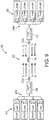
- FIG. 9 shows a fiber optical network that uses four pairs of bidirectional transceivers Trx#1-Trx#8 (of the type depicted in FIG. 7 ) with an optical cable 62 comprising a GbPOF 18 which has been subjected to the rapid cooling treatment disclosed herein. More specifically, FIG.
- FIG. 9 shows a bidirectional full-duplex data transmission system 60 having one full-duplex optical cable 62 for optically coupling four dual-wavelength single-fiber bidirectional transceivers Trx#1, Trx#3, Trx#5 and Trx#7 of one LRU set 64 of line replaceable units LRU#1, LRU#3, LRU#5 and LRU#7 to four dual-wavelength single-fiber bidirectional transceivers Trx#2, Trx#4, Trx#6 and Trx#8 of another LRU set 66 of line replaceable units LRU#2, LRU#4, LRU#6 and LRU#8.
- the eight dual-wavelength single-fiber bidirectional transceivers Trx#1-Trx#8 transmit light having different wavelengths ⁇ 1 to ⁇ 8 .
- the bidirectional full-duplex data transmission system 60 may comprise a first set of four glass optical fibers 24a, a first glass optical fiber coupler 70 connected to the first set of four glass optical fibers 24a, a second set of four glass optical fibers 24b and a second glass optical fiber coupler 68 connected to the second set of four glass optical fibers 24b.
- the four glass optical fibers 24a optically couple the glass optical fiber coupler 70 to the dual-wavelength single-fiber bidirectional transceivers Trx#2, Trx#4, Trx#6 and Trx#8, while the four glass optical fibers 24b optically couple the glass optical fiber coupler 68 to the dual-wavelength single-fiber bidirectional transceivers Trx#1, Trx#3, Trx#5 and Trx#7.
- the bidirectional full-duplex data transmission system 60 can further comprise a GbPOF 18 having one end connected to glass optical fiber coupler 70 by a connector 22a and another end connected to glass optical fiber coupler 68 by a connector 22b.
- the GbPOF 18 has a data rate capability of at least 10 gigabits per second at 100 degrees Celsius.
- the laser 4 in the transmitters of the bidirectional transceivers can be implemented with single-mode distributed feedback lasers, multi-mode Fabry-Perot lasers or vertical cavity surface-emitting lasers for high optical output power and low modal noise.
- the photodetector 8 in the receivers of the bidirectional transceivers can be implemented with a high-responsivity p-type intrinsic n-type (PIN) photodiode or an avalanche photodiode to provide high receiver sensitivity.
- PIN p-type intrinsic n-type
- Each of the glass optical fiber couplers 68 and 70 shown in FIG. 9 may comprise a 4x1 mode-independent multi-mode optical coupler (formed by heat fusing glass) that optically couples a respective set of four bidirectional transceivers to the opposing ends of the GbPOF 18.
- Respective ultra-low-reflection connectors 22a and 22b can be used to connect the outputs of the glass optical fiber couplers 68 and 70 to the opposing ends of the GbPOF 18.
- the end face of the glass optical fiber on one side of the glass optical fiber couplers and the confronting end face of the GbPOF 18 are angled and polished.
- the ultra-low-reflection connectors 22a and 22b are formed with a small angle at those end faces.
- FIG. 9 comprises a forward set of four line replaceable units optically communicating with an aft set of four line replaceable units on an airplane
- the concepts disclosed herein may be applied in situations where the number of line replaceable units in each of the forward and aft sets is different than four, for example, as few as two and perhaps as many as sixteen if the resulting optical losses are acceptable.
- the phrase "high-data-rate capability" means that the plastic optical fiber is capable of carrying data at a high data rate.
- high data rate means a data rate of at least one gigabit per second.
Landscapes
- Physics & Mathematics (AREA)
- Engineering & Computer Science (AREA)
- Optics & Photonics (AREA)
- General Physics & Mathematics (AREA)
- Manufacturing & Machinery (AREA)
- Health & Medical Sciences (AREA)
- Electromagnetism (AREA)
- Signal Processing (AREA)
- Computer Networks & Wireless Communication (AREA)
- Thermal Sciences (AREA)
- Ophthalmology & Optometry (AREA)
- Mechanical Engineering (AREA)
- Oral & Maxillofacial Surgery (AREA)
- Transportation (AREA)
- Aviation & Aerospace Engineering (AREA)
- Optical Couplings Of Light Guides (AREA)
- Optical Communication System (AREA)
- Optical Fibers, Optical Fiber Cores, And Optical Fiber Bundles (AREA)
Abstract
Description
- The technology disclosed herein generally relates to fiber optical networks that enable communication between electrical components.
- An optical fiber is a cylindrical dielectric waveguide that transmits light along its axis. The fiber consists of a transparent core surrounded by a transparent cladding layer (hereinafter "cladding"), both of which are made of dielectric materials. Light is kept in the core by the phenomenon of total internal reflection. To confine the optical signal in the core, the refractive index of the core is greater than that of the cladding. The boundary between the core and cladding may either be abrupt, as in step-index fiber, or gradual, as in graded-index fiber. Optical fibers can be made of glass or plastic.
- A plastic optical fiber capable of transmitting data at rates faster than 1 gigabits per second will be referred to herein as a "gigabit plastic optical fiber" (GbPOF). Gigabit plastic optical fiber has a core and cladding made of transparent carbon-hydrogen bond-free perfluorinated polymer. The perfluorinated polymer is ductile and does not break during tight cable bending. Commercially available examples of GbPOF have core diameters of 50 ± 5, 62.5 ± 5 and 120 ± 5 microns and a cladding diameter of 490 ± 10 microns. In contrast to a pure silica GOF core, a multi-mode GbPOF with the same core diameter is more imperfect with long random polymer chains in spaghetti shapes. These polymer chains create strong forward mode coupling and result in less reflected light that can interfere with the laser source. The strong mode coupling in a GbPOF core also reduces the coherency of the laser source and results in minimal modal interference along the fiber length.
- For the next generation of commercial airplanes, the avionics systems will include robust GbPOF for high-data-rate networks. But existing commercially available GbPOF can operate only up to 70 degrees Celsius, which is not suitable for use in avionics systems which operate at a temperature of 100 degrees Celsius.
- One existing solution is to use multi-mode glass optical fiber. The drawbacks of using multi-mode glass optical fiber include the following:
- (1) As compared to GbPOF, multi-mode glass optical fiber has the problem that of modal noise in an optical link that uses a gigabit transceiver with high-spectral-purity distributed feedback lasers. The GbPOF has a long chain of polymer in the fiber structure which homogenizes the propagation modes of the high-speed optical signal, eliminating the modal noise concern with the optical signal from distributed feedback lasers.
- (2) Multi-mode glass optical fiber has a smaller diameter (about 125 microns) as compare to GbPOF which has a 500-micron diameter. Thus, the multi-mode glass optical fiber is more fragile and easy to be damaged during installation. Glass optical fiber breakage has been a well-known problem that gives rise to high maintenance and installation costs in airplane production.
- Another existing solution is to develop customized high-temperature GbPOF. The drawbacks of customized high-temperature GbPOF are the following:
- (1) There is no proven polymer fabrication process that has made commercially available GbPOF capable of transmitting data at a high rate at an operating temperature of 100 degrees Celsius (hereinafter "100°C").
- (2) The current commercial fiber optic market's economy of scale is not supporting an infrastructure for a viable supplier of high-temperature GbPOF. As a result, the customized GbPOF is not a solution to the problem of having a reliable supply of high-temperature GbPOF for future high-data-rate avionics systems.
- A process capable of extending the operating temperature range of existing commercially available GbPOF would be useful in the manufacture of high-data-rate fiber optical networks.
- The subject matter disclosed in some detail below is directed to a process to enhance the performance of plastic optical fiber to operate with a high data rate (e.g., at least 1 gigabit per second) at high temperature (e.g., 100°C) for airplane avionic systems. Gigabit plastic optical fiber has a core including a dopant that enables data transmission at gigabit rates within an operating temperature range. The enhancement process proposed herein uses thermal cooling of the gigabit plastic optical fiber to stabilize the polymer matrix of the fiber. This rapid cooling treatment blocks dopant diffusion in a high-temperature environment, thereby avoiding degradation of the fiber's optical transmission characteristic (e.g., unacceptable increase in the optical loss characteristic and bandwidth reduction of the fiber). Stabilizing the dopant's distribution inside the GbPOF by a thermal cooling process enables the GbPOF to operate with a high data rate at up to 100°C.
- Various examples of a process for extending the operating temperature range of plastic optical fiber capable of transmitting data at a high rate (e.g., at least one gigabit per second) will be described in some detail below.
- One aspect of the subject matter disclosed in detail below is a process for extending the operating temperature range of plastic optical fiber, the method comprising: (a) placing a length of plastic optical fiber, for example a length in the form of a loop, inside a thermal chamber, which plastic optical fiber has a core with dopant distributed in a polymer matrix such that the plastic optical fiber has a high-data-rate capability at a first temperature but not at a second temperature which is higher than the first temperature; (b) decreasing a temperature inside the thermal chamber until a third temperature lower than the first temperature is reached; (c) maintaining the third temperature inside the thermal chamber for a first period of time sufficient to cause the plastic optical fiber to develop the high-data-rate capability at the second temperature; (d) increasing the temperature inside the thermal chamber until a fourth temperature lower than the first temperature and higher than the third temperature is reached; (e) maintaining the fourth temperature inside the thermal chamber during a second period of time subsequent to the first period of time; and (f) removing the loop of plastic optical fiber from the thermal chamber.
- The second temperature can be 100 degrees Celsius, the third temperature can be in a range of -55°C to -65°C and the fourth temperature can be room temperature. (As used herein, the term "room temperature" means 20°C to 25°C.) The plastic optical fiber is preferably a graded-index plastic optical fiber having a core and a cladding made of a transparent carbon-hydrogen bond-free perfluorinated polymer. Prior to the cooling treatment, the plastic optical fiber does not have a data rate capability of at least 10 gigabits per second at 100°C. Following the cooling treatment, the plastic optical fiber has a data rate capability of at least 10 gigabits per second at 100°C.
- Alternatively, when not in the form of a loop, opposing ends of the length of plastic optical fiber can be placed outside the thermal chamber. The process may further comprise: (g) optically coupling an optical transceiver to the opposing ends of the plastic optical fiber; and (h) electrically coupling a bit- error-rate tester to the optical transceiver, wherein steps (g) and (h) are performed after step (a) and before step (b). In this case, the process can further co: (i) testing the bit error rate of the plastic optical fiber at the high data rate. Step (i) may be performed twice: after step (h) and before step (b) and after step (e) and before step (f).
- A further aspect of the subject matter disclosed in detail below is a data transmission system comprising: an optical cable comprising a plastic optical fiber having first and second ends; a first transceiver optically coupled to the first end of the plastic optical fiber, the first transceiver comprising a laser disposed to transmit light into the plastic optical filter; a first electrical device configured for sending electrical signals representing data, the first electrical device being electrically coupled to the first transceiver; a second transceiver optically coupled to the second end of the plastic optical fiber, the second transceiver comprising a photodetector disposed to receive light from the plastic optical filter; a second electrical device configured for receiving electrical signals representing data, the second electrical device being electrically coupled to the second transceiver, wherein the plastic optical fiber has a data rate capability of at least 10 gigabits per second at 100°C. The plastic optical fiber is graded-index plastic optical fiber having a core and a cladding made of a transparent carbon-hydrogen bond-free perfluorinated polymer.
- In accordance with one proposed implementation of the data transmission system described in the immediately preceding paragraph, the first and second electrical devices are line replaceable units of an avionics network system onboard an airplane.
- In an aspect the disclosure is concerned with a process for extending the operating temperature range of plastic optical fiber, the method comprising:
- (a) placing a loop of plastic optical fiber inside a thermal chamber, which plastic optical fiber has a core with dopant distributed in a polymer matrix such that the plastic optical fiber has a high-data-rate capability at a first temperature but not at a second temperature which is higher than the first temperature;
- (b) decreasing a temperature inside the thermal chamber until a third temperature lower than the first temperature is reached;
- (c) maintaining the third temperature inside the thermal chamber for a first period of time sufficient to cause the plastic optical fiber to develop the high-data-rate capability at the second temperature;
- (d) increasing the temperature inside the thermal chamber until a fourth temperature lower than the first temperature and higher than the third temperature is reached;
- (e) maintaining the fourth temperature inside the thermal chamber during a second period of time subsequent to the first period of time; and
- (f) removing the loop of plastic optical fiber from the thermal chamber.
- The fourth temperature can be room temperature; the second temperature can be 100 degrees Celsius; the third temperature can be in a range of -55 to -65 degrees Celsius.
- The plastic optical fiber can be graded-index plastic optical fiber having a core and a cladding made of a transparent carbon-hydrogen bond-free perfluorinated polymer.
- Following completion of steps (a) through (f), the plastic optical fiber can have a data rate capability up to 10 gigabits per second at 100 degrees Celsius.
- After step (f), the plastic optical fiber can be installed in an avionics network system onboard an aircraft.
- In another aspect, the disclosure is concerned with a process for extending the operating temperature range of plastic optical fiber, the method comprising:
- (a) placing a portion of a length of plastic optical fiber inside a thermal chamber and opposing ends of the plastic optical fiber outside the thermal chamber, wherein the plastic optical has a core with dopant distributed in a polymer matrix such that the plastic optical fiber has a high-data-rate capability at a first temperature but not at a second temperature which is higher than the first temperature;
- (b) decreasing a temperature inside the thermal chamber until a third temperature lower than the first temperature is reached;
- (c) maintaining the third temperature inside the thermal chamber for a first period of time sufficient to cause the plastic optical fiber to develop the high-data-rate capability at the second temperature;
- (d) increasing the temperature inside the thermal chamber until a fourth temperature lower than the first temperature and higher than the third temperature is reached;
- (e) maintaining the fourth temperature inside the thermal chamber during a second period of time subsequent to the first period of time; and
- (f) removing the plastic optical fiber from the thermal chamber.
- An optical transceiver (2) can be optically coupled to the opposing ends of the plastic optical fiber (g); and
a bit-error-rate tester (28) can be electrically coupled to the optical transceiver (h),
wherein steps (g) and (h) are preferably performed after step (a) and before step (b). - The bit error rate of the plastic optical fiber can be tested at a high data rate (i).
- Step (i) is can be performed after step (h) and before step (b) or step (i) can be performed after step (e) and before step (f).
- The second temperature can be 100 degrees Celsius.
- The third temperature can be in a range of -55 to -65 degrees Celsius.
- The plastic optical fiber can be graded-index plastic optical fiber having a core and a cladding made of a transparent carbon-hydrogen bond-free perfluorinated polymer.
- Following completion of steps (a) through (f), the plastic optical fiber can have a data rate capability up to 10 gigabits per second at 100 degrees Celsius.
- The plastic optical fiber can be installed in an avionics network system onboard an aircraft after step (f).
- In a further aspect is disclosed a data transmission system comprising:
- an optical cable comprising a plastic optical fiber having first and second ends;
- a first transceiver optically coupled to the first end of the plastic optical fiber, the first transceiver comprising a laser disposed to transmit light into the plastic optical filter;
- a first electrical device configured for sending electrical signals representing data, the first electrical device being electrically coupled to the first transceiver;
- a second transceiver optically coupled to the second end of the plastic optical fiber, the second transceiver comprising a photodetector disposed to receive light from the plastic optical filter;
- a second electrical device configured for receiving electrical signals representing data, the second electrical device being electrically coupled to the second transceiver,
- wherein the plastic optical fiber has a data rate capability of at least 10 gigabits per second at 100 degrees Celsius.
- The plastic optical fiber can be graded-index plastic optical fiber having a core and a cladding made of a transparent carbon-hydrogen bond-free perfluorinated polymer.
- The first and second electrical devices can be line replaceable units of an avionics network system onboard an airplane.
- The plastic optical fiber can be treated by cooling at a temperature in a range of -55 to -65 degrees Celsius prior to being optically coupled to the first and second transceivers.
- Other aspects of a process for extending the operating temperature range of plastic optical fiber capable of transmitting data at a high rate are disclosed below.
- The features, functions and advantages discussed in the preceding section can be achieved independently in various examples or may be combined in yet other examples Various examples will be hereinafter described with reference to drawings for the purpose of illustrating the above-described and other aspects. None of the diagrams briefly described in this section are drawn to scale.
-
FIG. 1 is a diagram showing the chemical composition of one commercially available transparent carbon-hydrogen bond-free perfluorinated polymer. -
FIG. 2 is a diagram representing the structure of a GbPOF consisting of a doped polymer matrix. The repeating subunits of the linear polymer chains are represented by dark-shaded circles, while the distribution of dopant molecules is represented by light-shaded circles. -
FIG. 3 is a diagram representing a sectional view of a GbPOF consisting of a core made of a doped polymer matrix and a polymer cladding surrounding the core. -
FIG. 4 is a block diagram identifying components of an experimental set up for rapid cooling of loops of GbPOF. -
FIG. 5 is a diagram identifying some features of a dual-fiber bidirectional transceiver design in which the transceiver transmits and receives light of the same wavelength. -
FIGS. 6A and6B are respective portions of a flowchart identifying steps of a process for extending the operating temperature range of gigabit plastic optical fiber. -
FIG. 7 is a diagram identifying some features of a single-fiber bidirectional transceiver design in which the transceiver transmits light having a first wavelength and receives light having a second wavelength different than the first wavelength. -
FIG. 8 is a diagram identifying some features of a bidirectional full-duplex data transmission system comprising one pair of dual-wavelength single-fiber bidirectional transceivers, each dual-wavelength single-fiber bidirectional transceivers being of the type depicted inFIG. 7 . -
FIG. 9 is a diagram identifying components of a bidirectional full-duplex data transmission system having one full-duplex optical cable connecting the dual-wavelength single-fiber bidirectional transceivers of one set of line replaceable units to the dual-wavelength single-fiber bidirectional transceivers of another set of line replaceable units, each dual-wavelength single-fiber bidirectional transceiver transmitting light at a different wavelength. - Reference will hereinafter be made to the drawings in which similar elements in different drawings bear the same reference numerals.
- Illustrative examples of a process for extending the operating temperature range of plastic optical fiber capable of transmitting data at a high rate are described in some detail below.
- Various examples of a fiber optical network for enabling optical communication between line replaceable units on an airplane at high data transmission rates (e.g., greater than 1 Gbit/sec) will be described in detail below for the purpose of illustration. However, implementation of the fiber optical networks disclosed herein is not limited solely to the environment of an airplane, but rather may be utilized in fiber optical networks onboard other types of vehicles or other types of fiber optical networks (e.g., long-distance terrestrial, data center and fiber-to-the-home/office applications).
-
FIG. 1 is a structural formula showing the chemical composition of one commercially available transparent carbon-hydrogen bond-free perfluorinated polymer. This graphic representation of the molecular structure shows how the atoms are possibly arranged in the real three-dimensional space. The chemical bonding within the molecule is also shown. The letter "n" indicates that the molecule is a repeating unit in a chain. The perfluorinated polymer depicted inFIG. 1 has fluorine atoms bonded to the carbon atoms instead of having hydrogen atoms bonded to the carbon atoms. An optical fiber having a core and cladding made of perfluorinated polymer enables higher data rates when used in large-capacity communications systems. - Basically, GbPOF is made of long chains of polymers with dopant mixed in the polymer chains. The polymers of the GbPOF are chemically bonded, but the dopant is not chemically bonded to the polymers. This is shown schematically in
FIG. 2 ; the diagram represents the structure of a GbPOF consisting of a dopedpolymer matrix 40. The repeating subunits of thelinear polymer chains 42 are represented by dark-shaded circles, while the distribution ofdopant molecules 44 is represented by light-shaded circles. In general, in the case of GbPOF, the dopant molecules are impurities intentionally introduced to the GbPOF polymer chains during the GbPOF fabrication process. Dopant distribution in the host polymers can be altered by high temperature. This is the well-known "impurity diffusion" process, which drives the impurity from a high-density region to a lower-density region. -
FIG. 3 is a diagram representing a sectional view of a graded-index GbPOF 50 consisting of a core 52, acladding 54 surrounding thecore 52, and an over-cladding 56 surrounding thecladding 54. Thecore 52 andcladding 54 are made of the same transparent carbon-hydrogen bond-free perfluorinated polymer material; the over-cladding 56 is made of a polymeric material. What enables the graded-index GbPOF 50 to operate at high data rates is the dopant that is distributed in the center of the core of the GbPOF with a gradient (or Gaussian) index profile as indicated by shading inFIG. 3 . If the distribution of this gradient index profile is altered or degraded, the bandwidth of the GbPOF will change and the GbPOF will not be able to support the high data rate operation. In the case of graded-index GbPOF 50, a high-dopant-density region is located at the center of the core 52 (indicated by dark shading); the low-dopant-density region is located in the outer core region (indicated by light shading). The dopant diffusion process is enhanced by high temperature. This is the primary reason why one supplier limits the operation of a commercially available GbPOF to 70°C. This dopant-out diffusion process is enhanced by the thermal activity of the polymer chains in the host GbPOF. If the thermal activity of the polymer chains is reduced, then the redistribution of the dopant is reduced. - This disclosure proposes a process for treating the GbPOF to stabilize or "lock-in" the distribution of dopant in the optical polymer matrix of the core 52 by rapid cooling. Experiments were performed which demonstrated that the rapid cooling process proposed herein enables the commercially available GbPOF to operate with a bandwidth up to 10 Gbits/sec at a temperature of 100°C. More specifically, experiments were performed to determine the effects of exposing a commercially available GbPOF to a temperature of 100°C for 24 hours. The experimental findings showed that the transparency of the commercially available GbPOF was not adversely affected by extended exposure to a temperature of 100°C, but the bandwidth was adversely affected by extended exposure to a temperature of 100°C.
-
FIG. 4 is a block diagram identifying components of an experimental set-up for rapid cooling of loops of GbPOF. The experimental set-up includes athermal chamber 30, a temperature sensor 32 (e.g., a thermocouple) which is thermally coupled to the inside thethermal chamber 30, and athermometer 34 which is electrically coupled to thetemperature sensor 32. Thetemperature sensor 32 outputs an electrical signal that is a measure of the temperature inside thethermal chamber 30. For example, a thermocouple produces a temperature-dependent voltage as a result of the thermoelectric effect. Thethermometer 34 converts this temperature-dependent voltage into a numerical value that is displayed on a display screen. - A host computing system (not shown in
FIG. 4 ) is in communication with a data system by which a technician can download various parameters and profiles. The downloaded parameters include a desired setpoint chamber temperature at which to operate thethermal chamber 30 during the rapid cooling process disclosed herein. To attain this setpoint chamber temperature within the thermal chamber, a processor runs software that implements a dual-loop feedback control system based on temperatures measured in thethermal chamber 30. - The experimental design was to treat three loops of graded-index GbPOF differently and then measure the respective properties of the loops to determine the differences attributable to the treatment process used. As depicted in
FIG. 4 , each loop ofGbPOF 18 was placed inside thethermal chamber 30, but the respective ends of theGbPOF 18 were passed through the wall of and located exterior to thethermal chamber 30. - Still referring to
FIG. 4 , the experimental set-up further includes anoptical transceiver 2 capable of transmitting and receiving data at a rate of at least one gigabit per second and a bit-error-rate tester 28 which is electrically coupled to theoptical transceiver 2. In addition, the ends of theGbPOF 18 are optically coupled to theoptical transceiver 2. During testing, theoptical transceiver 2 transmitted and received data at a rate of 10 gigabits per second via theGbPOF 18. During data transmission, the temperature inside thethermal chamber 30 was controlled to be close to if not exactly equal to a specified target temperature to which the loop ofGbPOF 18 inside thethermal chamber 30 was exposed. The actual temperature inside thethermal chamber 30 was measured by thetemperature sensor 32 and displayed by thethermometer 34. -
FIG. 5 is a diagram identifying some components of a dual-fiber bidirectional optical transceiver 2 (hereinafter "optical transceiver") suitable for use in an experimental set-up of the type described herein. Theoptical transceiver 2 transmits and receives light of the same wavelength. [As used herein, the term "wavelength" in the context of coherent laser light means the center wavelength of laser light having a narrow bandwidth.] In this example, theoptical transceiver 2 includes alaser 4 and aphotodetector 8. Thelaser 4 is optically coupled to one end of theGbPOF 18, while thephotodetector 8 is optically coupled to the other end of theGbPOF 18. Thelaser 4 is driven to emit light of a wavelength λ1 by a laser driver and transmitcircuit 6 in response to receipt of differential transmit signals Tx+ and Tx- from the bit-error-rate tester 28 (not shown inFIG. 5 ) via transmitelectrical signal lines circuit 6 comprises electrical circuitry that converts those electrical differential signals to electrical digital signals representing the data to be transmitted by thelaser 4. Conversely, thephotodetector 8 receives light of wavelength λ1 and converts that detected light into electrical digital signals which are provided to a detector amplifier and receivecircuit 10. The detector amplifier and receivecircuit 10 in turn comprises electrical circuitry that converts those electrical digital signals to electrical differential receive signals Rx+ and Rx- representing the data received. The electrical differential receive signals Rx+ and Rx- are transmitted to the bit-error-rate tester 28 via receiveelectrical signal lines fiber bidirectional transceiver 2 receives electrical power having a voltage Vcc via transceiverpower supply line 16. - In the experiments that were conducted, three loops of commercially available graded-index GbPOF, each 30 meters in length, were labeled as
Loop # 1,Loop # 2 andLoop # 3. These three loops of GbPOF were tested for bit error rate using a 10 Gbits/sec optical signal at room temperature. All three loops were operating properly without any bit error at room temperature. After the bit-error-rate testing, the temperature treatment disclosed herein was applied to the three loops of GbPOF as follows: -
Loop # 1 was placed in athermal chamber 30 with an optical signal coupled into the loop and then rapidly cooled to -55°C. The temperature insidethermal chamber 30 was maintained at -55°C for one hour before warming back to room temperature. -
Loop # 2 was placed in thethermal chamber 30 without an optical signal coupled into the loop and then rapidly cooled to -55°C. The temperature insidethermal chamber 30 was maintained at -55°C for one hour before warming back to room temperature. -
Loop # 3 was not placed in thethermal chamber 30 and was not treated with any cooling process. - After rapid cooling of
GbPOF Loop # 1 andLoop # 2, all three GbPOF loops were put inside another thermal oven (not shown), which was then set to a temperature of 100°C for over 24 hours. During the 24 hours, the optical losses of the three loops were monitored and recorded every 15 minutes. The optical power coupled into each GbPOF loop was stable without any degradation, meaning that the transparency of the GbPOF is not adversely affected by operation at high temperature. - The results of heating the three loops GbPOF to a temperature of 100°C showed that the commercially available GbPOF loops did not suffer any optical loss with a long duration of 100°C heating. After the heating process, bit-error-rate testing was performed at -55°C, room temperature and 100°C for
Loops # 1, #2 and #3 at a data rate of 10 Gbits/sec. The results of the bit-error-rate testing for the three loops were then compared. The bit-error-rate test results showed thatLoop # 2 had no bit errors for all three temperatures. - Eye diagram testing was also performed for at a data rate of 10 Gbits/sec on all three GbPOF loops at -55°C, room temperature and 100°C. The results showed that all three GbPOF loops were operating satisfactorily at 10 Gbits/sec after the extended 100°C heating process.
- In addition, near-field optical measurements of the three loops of GbPOF were made after heating for more than 24 hours at a temperature of 100°C. The near-field test results showed that
Loop # 2 had a higher concentration of the optical power in the core of the GbPOF loop than didLoops # 1 and #3. I - In summary, the post100°C heating results showed that
Loop # 2 had the best high-data-rate (up to 10 Gbits/sec) performance after more than 24 hours of 100°C heating.Loop # 2 also showed the best confinement of the optical signal to the center of the fiber core according to the near-field measurement results, which indicates that the dopant concentration profile is better maintained inLoop # 2 than in the other two loops after the extended 100°C heating process. These experimental results are consistent with the theory (described above) that if the distribution of the gradient index profile is altered or degraded, the bandwidth of the GbPOF will change and will not be able to support high-data-rate operation. Furthermore,Loops # 1 and #2 were both rapidly cooled, butLoop # 2 had no optical injection during the cooling process, which indicates that the carbon-hydrogen bond-free perfluorinated polymer is more stable without the optical excitation during the rapid thermal "lock-in" process. -
FIGS. 6A and6B are respective portions of a flowchart identifying steps of aprocess 100 for extending the operating temperature range of gigabit plastic optical fiber. More specifically, a rapid thermal cooling process is proposed herein to enhance the high-data-rate operation of a commercially available GbPOF at temperatures up to 100°C. - To start the process 100 (see
FIG. 6A ), both ends of the GbPOF loop are terminated with the required length with proper connectors, typically LC (Lucent Corporation) connectors (step 102). LC connectors are push-pull connectors that utilize a latch to connect to a device. The GbPOF loop is then placed inside athermal chamber 30 with side feed through for the GbPOF loop (step 104). The two terminated ends of the GbPOF loop are then fed through the side wall of the thermal chamber 30 (step 106). The result ofsteps thermal chamber 30 while opposing ends of the GbPOF is outside thethermal chamber 30. The GbPOF has a core with dopant distributed in a polymer matrix such that the plastic optical fiber has a high-data-rate capability at a first temperature (e.g., 70°C) but not at a second temperature (e.g., 100°C). - Still referring to
FIG. 6A , the terminated ends of the GbPOF loop are then connected to anoptical transceiver 2 having the capability to transmit data at a data rate of 10 Gbits/sec (step 108). A first end of the GbPOF is optically coupled to the transmitter of theoptical transceiver 2; a second end of the GbPOF is optically coupled to the receiver of theoptical transceiver 2. Theoptical transceiver 2 is then connected to the bit-error-rate (BER) tester 28 (step 110). Then theoptical transceiver 2 is powered up and the bit-error-rate tester 28 is activated to perform bit-error-rate testing to make sure no bit errors are occurring (step 112). After the bit-error-rate testing has been completed, the electric power to theoptical transceiver 2 is turned off to make sure no optical signal is coupled to the GbPOF loop during the cooling process (step 114). - The temperature inside the
thermal chamber 30 is then rapidly decreased until a pre-set cooling temperature (referred to as the "third temperature" in the claims) is reached (step 116). The cooling temperature is in a range of -55°C to -65°C. The technician then waits 15 minutes for the cooling temperature inside thethermal chamber 30 to stabilize (step 118). Following stabilization of the cooling temperature, the cooling temperature inside thethermal chamber 30 is maintained substantially constant for a first period of time (e.g., for one hour) sufficient to cause the GbPOF to develop a high-data-rate capability at high temperature (e.g., 100°C) (step 120). Referring now toFIG. 6B , the temperature inside thethermal chamber 30 is then increased until a temperature (referred to as the "fourth temperature" in the claims) higher than the cooling temperature is reached (step 122). In accordance with one proposed implementation, the "fourth temperature" is room temperature. The technician then waits 15 minutes for the fourth temperature inside thethermal chamber 30 to stabilize (step 124). The fourth temperature is maintained inside the thermal chamber during a second period of time (e.g., one-half hour) subsequent to the first period of time (step 126). All changes in the temperature inside the thermal chamber are initiated by the technician interfacing with an input device that sets the target temperature inside thethermal chamber 30. - Upon completion of the cooling process, the
optical transceiver 2 is powered up and the bit-error-rate tester 28 is activated to perform bit-error-rate testing while the GbPOF loop is still inside thethermal chamber 30 at room temperature (step 128). Upon completion of the bit-error-rate test, the ends of the GbPOF loop are disconnected from the optical transceiver (step 130) and then the GbPOF loop is removed from the thermal chamber 132). - The technician then analyzes the bit-error-rate test results. A determination is made whether the test results show that the bit error rate is within engineering specifications or not (step 134). On the one hand, if a determination is made in
step 130 that the bit error rate is within engineering specifications, then the GbPOF loop is classified as being suitable for use in a high-temperature environment (step 136). On the other hand, if a determination is made instep 130 that the bit error rate is not within engineering specifications, then the GbPOF loop is classified as being unsuitable for use in a high-temperature environment (step 138). - In accordance with another example a GbPOF loop may be placed inside a
thermal chamber 30 and cooled without performing bit-error-rate testing while the GbPOF loop is inside thethermal chamber 30. The GbPOF has a core with dopant distributed in a polymer matrix such that the plastic optical fiber has a high-data-rate capability at a first temperature but not at a second temperature which is higher than the first temperature. The temperature inside thethermal chamber 30 is decreased until a third temperature lower than the first temperature is reached. The third temperature inside thethermal chamber 30 is maintained for a first period of time sufficient to cause the GbPOF to develop the high-data-rate capability at the second temperature. Then the temperature inside thethermal chamber 30 is increased until a fourth temperature lower than the first temperature and higher than the third temperature is reached. The fourth temperature inside thethermal chamber 30 is then maintained during a second period of time subsequent to the first period of time. Thereafter the loop of GbPOF is removed from thethermal chamber 30. - An optical cable including a
GbPOF 18 which has been cooled and successfully tested as disclosed above may be employed in an avionics network system onboard an aircraft. One example of such a usage will now be described with reference toFIGS. 7-9 . -
FIG. 7 is a diagram identifying some features of a single-fiber full-duplex bidirectional transceiver design in which the dual-wavelength single-fiber bidirectional transceiver 20 transmits light having a first wavelength λ1 and receives light having a second wavelength λ2 different than the first wavelength λ1 via the sameoptical fiber 24. The dual-wavelength single-fiber bidirectional transceiver 20 comprises alaser 4 and aphotodetector 8. Thelaser 4 is driven to emit light of a wavelength λ1 by a laser driver and transmitcircuit 6 in response to receipt of differential transmit signals Tx+ and Tx- from an associated line replaceable unit (not shown) via transmitelectrical signal lines circuit 6 comprises electrical circuitry as previously described with reference toFIG. 5 . Conversely, thephotodetector 8 receives light of wavelength λ2 and converts that detected light into electrical digital signals which are provided to a detector amplifier and receivecircuit 10. The detector amplifier and receivecircuit 10 in turn comprises electrical circuitry as previously described with reference toFIG. 5 . - The dual-wavelength single-
fiber bidirectional transceiver 20 depicted inFIG. 7 is capable of single-fiber operation because it is equipped in its optical front end with a wavelength-division multiplexing (WDM) filter (hereinafter "WDM filter 26") which passes the optical signal from thelaser 4 at one wavelength λ1 and reflects the received optical signal at a different wavelength λ2 toward thephotodetector 8. TheWDM filter 26 inside of the dual-wavelength single-fiber bidirectional transceiver 20 is a wavelength-selective bandpass filter designed in accordance with a high cross-talk isolation technique. Use of such isolation ensures that the optical signal from thelocal laser 4 is not detected by the receiver in the same bidirectional transceiver. -
FIG. 8 is a diagram identifying some features of a bidirectional full-duplexdata transmission system 46 comprising one pair of dual-wavelength single-fiberbidirectional transceivers fiber bidirectional transceiver FIG. 7 . In this example, thelaser 4 of the dual-wavelength single-fiber bidirectional transceiver 20a is optically coupled to emit light toward thephotodetector 8 of the dual-wavelength single-fiber bidirectional transceiver 20b via anoptical cable 48 comprising anoptical fiber 24a, aconnector 22a, aGbPOF 18 which has been subjected to the rapid cooling treatment disclosed herein, aconnector 22b and anoptical fiber 24b connected in series. Thelaser 4 of the dual-wavelength single-fiber bidirectional transceiver 20b is optically coupled to emit light toward to thephotodetector 8 of the dual-wavelength single-fiber bidirectional transceiver 20a via the sameoptical cable 48. The dual-wavelength single-fiber bidirectional transceiver 20a transmits light having a wavelength λ1 and receives light having a wavelength receives λ2. Conversely, the dual-wavelength single-fiber bidirectional transceiver 20b transmits light having a wavelength λ2 and receives light having a wavelength receives λ1. Each of the dual-wavelength single-fiberbidirectional transceivers WMD filter 26 that passes light having a wavelength λ1 and reflects light having a wavelength λ2. The bidirectional full-duplexdata transmission system 46 depicted inFIG. 8 is capable of transmitting data at a rate greater than 1 Gbit/sec in either direction while exposed to a temperature of 100°C due to the presence ofGbPOF 18 in theoptical cable 48. -
FIG. 9 shows a fiber optical network that uses four pairs of bidirectional transceivers Trx#1-Trx#8 (of the type depicted inFIG. 7 ) with anoptical cable 62 comprising aGbPOF 18 which has been subjected to the rapid cooling treatment disclosed herein. More specifically,FIG. 9 shows a bidirectional full-duplexdata transmission system 60 having one full-duplexoptical cable 62 for optically coupling four dual-wavelength single-fiber bidirectionaltransceivers Trx# 1,Trx# 3,Trx# 5 andTrx# 7 of one LRU set 64 of line replaceableunits LRU# 1,LRU# 3,LRU# 5 andLRU# 7 to four dual-wavelength single-fiber bidirectionaltransceivers Trx# 2,Trx# 4,Trx# 6 andTrx# 8 of another LRU set 66 of line replaceableunits LRU# 2,LRU# 4,LRU# 6 andLRU# 8. The eight dual-wavelength single-fiber bidirectional transceivers Trx#1-Trx# 8 transmit light having different wavelengths λ1 to λ8. - The bidirectional full-duplex
data transmission system 60 may comprise a first set of four glassoptical fibers 24a, a first glassoptical fiber coupler 70 connected to the first set of four glassoptical fibers 24a, a second set of four glassoptical fibers 24b and a second glassoptical fiber coupler 68 connected to the second set of four glassoptical fibers 24b. The four glassoptical fibers 24a optically couple the glassoptical fiber coupler 70 to the dual-wavelength single-fiber bidirectionaltransceivers Trx# 2,Trx# 4,Trx# 6 andTrx# 8, while the four glassoptical fibers 24b optically couple the glassoptical fiber coupler 68 to the dual-wavelength single-fiber bidirectionaltransceivers Trx# 1,Trx# 3,Trx# 5 andTrx# 7. The bidirectional full-duplexdata transmission system 60 can further comprise aGbPOF 18 having one end connected to glassoptical fiber coupler 70 by aconnector 22a and another end connected to glassoptical fiber coupler 68 by aconnector 22b. TheGbPOF 18 has a data rate capability of at least 10 gigabits per second at 100 degrees Celsius. - The
laser 4 in the transmitters of the bidirectional transceivers can be implemented with single-mode distributed feedback lasers, multi-mode Fabry-Perot lasers or vertical cavity surface-emitting lasers for high optical output power and low modal noise. - The
photodetector 8 in the receivers of the bidirectional transceivers can be implemented with a high-responsivity p-type intrinsic n-type (PIN) photodiode or an avalanche photodiode to provide high receiver sensitivity. - Each of the glass
optical fiber couplers FIG. 9 may comprise a 4x1 mode-independent multi-mode optical coupler (formed by heat fusing glass) that optically couples a respective set of four bidirectional transceivers to the opposing ends of theGbPOF 18. Respective ultra-low-reflection connectors optical fiber couplers GbPOF 18. For example, the end face of the glass optical fiber on one side of the glass optical fiber couplers and the confronting end face of theGbPOF 18 are angled and polished. The ultra-low-reflection connectors - Although the example depicted in
FIG. 9 comprises a forward set of four line replaceable units optically communicating with an aft set of four line replaceable units on an airplane, the concepts disclosed herein may be applied in situations where the number of line replaceable units in each of the forward and aft sets is different than four, for example, as few as two and perhaps as many as sixteen if the resulting optical losses are acceptable. - While processes for extending the operating temperature range of plastic optical fiber capable of transmitting data at a high rate have been described with reference to various embodiments, it will be understood by those skilled in the art that various changes may be made and equivalents may be substituted for elements thereof without departing from the teachings herein. In addition, many modifications may be made to adapt the concepts and reductions to practice disclosed herein to a particular situation. Accordingly, it is intended that the subject matter covered by the claims not be limited to the disclosed embodiments.
- The method claims set forth hereinafter should not be construed to require that the steps recited therein be performed in alphabetical order (any alphabetical ordering in the claims is used solely for the purpose of referencing previously recited steps) or in the order in which they are recited unless the claim language explicitly specifies or states conditions indicating a particular order in which some or all of those steps are performed. Nor should the method claims be construed to exclude any portions of two or more steps being performed concurrently or alternatingly unless the claim language explicitly states a condition that precludes such an interpretation.
- As used in the claims, the phrase "high-data-rate capability" means that the plastic optical fiber is capable of carrying data at a high data rate. As used in the claims, the term "high data rate" means a data rate of at least one gigabit per second.
Claims (15)
- A process for extending the operating temperature range of plastic optical fiber, the method comprising:(a) placing a length of plastic optical fiber (18) inside a thermal chamber (30), which plastic optical fiber has a core (52) with dopant (44) distributed in a polymer matrix (40) such that the plastic optical fiber has a high-data-rate capability at a first temperature but not at a second temperature which is higher than the first temperature;(b) decreasing a temperature inside the thermal chamber until a third temperature lower than the first temperature is reached;(c) maintaining the third temperature inside the thermal chamber for a first period of time sufficient to cause the plastic optical fiber to develop the high-data-rate capability at the second temperature;(d) increasing the temperature inside the thermal chamber until a fourth temperature lower than the first temperature and higher than the third temperature is reached;(e) maintaining the fourth temperature inside the thermal chamber during a second period of time subsequent to the first period of time; and(f) removing the lengthof plastic optical fiber from the thermal chamber.
- The process according to claim 1, wherein the length of plastic optical fiber (18) is in the form of a loop.
- The process according to claim 1, wherein opposing ends of the length of the plastic optical fiber are placed outside the thermal chamber.
- The process as recited in any of the claims 1 to 3, wherein the fourth temperature is room temperature.
- The process as recited in any of the claims 1 to 4, wherein the second temperature is 100 degrees Celsius.
- The process as recited in any of the claims 1 to 5, wherein the third temperature is in a range of -55 to -65 degrees Celsius.
- The process as recited in any of the claims 1 to 6, wherein the plastic optical fiber is graded-index plastic optical fiber having a core (52) and a cladding (54) made of a transparent carbon-hydrogen bond-free perfluorinated polymer.
- The process as recited in any of the claims 1 to 7, wherein following completion of steps (a) through (f), the plastic optical fiber has a data rate capability up to 10 gigabits per second at 100 degrees Celsius.
- The process as recited in any of the claims 1 to 8, further comprising installing the plastic optical fiber in an avionics network system (46, 60) onboard an aircraft after step (f).
- The process as recited in any of the claims 3 to 9, further comprising:(g) optically coupling an optical transceiver (2) to the opposing ends of the plastic optical fiber; and(h) electrically coupling a bit-error-rate tester (28) to the optical transceiver,wherein steps (g) and (h) are performed after step (a) and before step (b).
- The process as recited in claim 10, further comprising:
(i) testing the bit error rate of the plastic optical fiber at a high data rate. - The process as recited in claim 11, wherein step (i) is performed after step (h) and before step (b).
- The process as recited in claim 11, wherein step (i) is performed after step (e) and before step (f).
- A data transmission system comprising:an optical cable (18) comprising a plastic optical fiber having first and second ends;a first transceiver (20a) optically coupled to the first end of the plastic optical fiber, the first transceiver comprising a laser (4) disposed to transmit light into the plastic optical filter;a first electrical device (64) configured for sending electrical signals representing data, the first electrical device being electrically coupled to the first transceiver;a second transceiver (20b) optically coupled to the second end of the plastic optical fiber, the second transceiver comprising a photodetector (8) disposed to receive light from the plastic optical filter;a second electrical device (66) configured for receiving electrical signals representing data, the second electrical device being electrically coupled to the second transceiver,wherein the plastic optical fiber has a data rate capability of at least 10 gigabits per second at 100 degrees Celsius.
- The data transmission system according to claim 14, wherein the plastic optical fiber is graded index plastic optical fiber having a core (52) and a cladding (54) made of a transparent carbon-hydrogen bond free perfluorinated polymer.
Applications Claiming Priority (1)
| Application Number | Priority Date | Filing Date | Title |
|---|---|---|---|
| US16/551,282 US10998976B2 (en) | 2019-08-26 | 2019-08-26 | Process for extending operating temperature range of gigabit plastic optical fiber |
Publications (3)
| Publication Number | Publication Date |
|---|---|
| EP3786675A2 true EP3786675A2 (en) | 2021-03-03 |
| EP3786675A3 EP3786675A3 (en) | 2021-04-21 |
| EP3786675B1 EP3786675B1 (en) | 2024-09-04 |
Family
ID=71899591
Family Applications (1)
| Application Number | Title | Priority Date | Filing Date |
|---|---|---|---|
| EP20188923.5A Active EP3786675B1 (en) | 2019-08-26 | 2020-07-31 | Process for extending operating temperature range of gigabit plastic optical fiber |
Country Status (5)
| Country | Link |
|---|---|
| US (1) | US10998976B2 (en) |
| EP (1) | EP3786675B1 (en) |
| KR (1) | KR102899602B1 (en) |
| CN (1) | CN112433292B (en) |
| TW (1) | TWI844695B (en) |
Family Cites Families (12)
| Publication number | Priority date | Publication date | Assignee | Title |
|---|---|---|---|---|
| JP2533778B2 (en) * | 1987-06-19 | 1996-09-11 | 旭化成工業株式会社 | Reinforced ion exchange membrane and method for producing the same |
| US6146713A (en) * | 1999-03-25 | 2000-11-14 | Acme Grating Ventures, Llc | Optical transmission systems and apparatuses including Bragg gratings and methods of making |
| US6395838B1 (en) * | 2000-01-19 | 2002-05-28 | E. I. Du Pont De Nemours And Company | Process for making graft copolymers |
| FR2832412B1 (en) * | 2001-11-19 | 2003-12-19 | Atofina | CROSSLINKABLE FUNCTIONAL POLYMER FOR THE MANUFACTURE OF LIGHT CONDUCTING MATERIALS |
| ATE346316T1 (en) | 2003-02-10 | 2006-12-15 | Nanoptics Inc | METHOD AND APPARATUS FOR PRODUCING OPTICAL TRANSMISSION MEDIA |
| FR2890182B1 (en) | 2005-08-24 | 2008-04-18 | Nexans Sa | INDEX GRADIENT OPTICAL PERFORATED FIBER AND PROCESS FOR PRODUCING SUCH A FIBER |
| US8326157B2 (en) | 2009-06-30 | 2012-12-04 | Cambridge Enterprise Limited | High-speed optical transceiver, a bi-directional duplex optical fiber link, and a method for providing a bi-directional duplex optical fiber link |
| EP2418523B1 (en) * | 2010-08-12 | 2016-10-05 | Draka Comteq B.V. | Depressed graded index multi-mode optical fiber |
| JP6356693B2 (en) * | 2012-12-04 | 2018-07-11 | スリーエム イノベイティブ プロパティズ カンパニー | Highly fluorinated polymer |
| JP2019049658A (en) | 2017-09-11 | 2019-03-28 | 小池 康博 | Optical fiber cable |
| CN207304589U (en) * | 2017-10-26 | 2018-05-01 | 武汉大学 | Aerospace vehicle communication system based on plastic optical fiber CAN bus |
| US10447423B2 (en) | 2017-11-03 | 2019-10-15 | The Boeing Company | Bidirectional, multi-wavelength gigabit optical fiber network |
-
2019
- 2019-08-26 US US16/551,282 patent/US10998976B2/en active Active
-
2020
- 2020-06-22 TW TW109121161A patent/TWI844695B/en active
- 2020-07-28 KR KR1020200093899A patent/KR102899602B1/en active Active
- 2020-07-31 EP EP20188923.5A patent/EP3786675B1/en active Active
- 2020-08-25 CN CN202010861911.9A patent/CN112433292B/en active Active
Also Published As
| Publication number | Publication date |
|---|---|
| CN112433292A (en) | 2021-03-02 |
| US10998976B2 (en) | 2021-05-04 |
| EP3786675B1 (en) | 2024-09-04 |
| TW202113406A (en) | 2021-04-01 |
| KR102899602B1 (en) | 2025-12-11 |
| US20210067250A1 (en) | 2021-03-04 |
| KR20210025480A (en) | 2021-03-09 |
| TWI844695B (en) | 2024-06-11 |
| EP3786675A3 (en) | 2021-04-21 |
| CN112433292B (en) | 2024-03-22 |
Similar Documents
| Publication | Publication Date | Title |
|---|---|---|
| US7184623B2 (en) | Apparatus, system and method for an adiabatic coupler for multi-mode fiber-optic transmission systems | |
| US10447423B2 (en) | Bidirectional, multi-wavelength gigabit optical fiber network | |
| US9279741B2 (en) | Method of measuring multi-mode fiber optical properties during processing of the fiber | |
| US7283701B2 (en) | Optical fiber transmission system with increased effective modal bandwidth transmission | |
| US20060051017A1 (en) | Optical fiber transmission system with increased effective modal bandwidth transmission | |
| US10574359B2 (en) | Single-wavelength bidirectional transceiver with integrated optical fiber coupler | |
| US20140092380A1 (en) | Method of measuring multi-mode fiber bandwidth through accessing one fiber end | |
| Chen et al. | A fiber modal adapter for upgrading 850 nm multimode fiber links to 1310 nm single-mode transmission | |
| EP3786675B1 (en) | Process for extending operating temperature range of gigabit plastic optical fiber | |
| Ishigure et al. | Mode-coupling control and new index profile of GI POF for restricted-launch condition in very-short-reach networks | |
| Liu et al. | High-speed performance evaluation of graded-index multicore fiber compatible with multimode and quasi-single mode operation | |
| Zakharian et al. | Impact of multi-path interference on single mode transmission over multi-mode fibers | |
| Chen et al. | Concept of BiDi Optimized OM4 Multimode Fiber for High Date Rate Short Reach VCSEL Transmission | |
| Castro et al. | Low latency transmission over 400 m hollow-core-fiber cable at 100G PAM-4 per wavelength | |
| US20250052945A1 (en) | Smf to mmf coupler | |
| Liu et al. | A Mode Field Adapter for Single Mode Fibre to Multimode Fibre Based on Fibre Core Thermal Diffusion | |
| Chen et al. | A Simple and Compact Fiber Modal Adapter for Upgrading 850 nm Multimode Fibers for Fundamental Mode Transmission at 1310 nm | |
| Liu et al. | Graded-index seven-core fiber optimized for high density and ultra-wideband parallel transmission application | |
| Chen et al. | Mode Division Multiplexed Transmission over Elliptical Core Few Mode Fiber with Non-Degenerate LP11 Modes Using Mode Selective Coupler Based Multiplexers | |
| Zhu et al. | 7 x10-Gb/s multicore multimode fiber transmissions for parallel optical data links | |
| Zhu et al. | 7× 10-Gb/s multicore multimode fiber transmissions for parallel optical data links | |
| Lingle et al. | Multimode fibers optimized for high speed, short reach interconnects | |
| Chen et al. | Chromatic Dispersion Compensated 25Gb/s Multimode VCSEL Transmission Assisted with a MMF Jumper |
Legal Events
| Date | Code | Title | Description |
|---|---|---|---|
| PUAI | Public reference made under article 153(3) epc to a published international application that has entered the european phase |
Free format text: ORIGINAL CODE: 0009012 |
|
| STAA | Information on the status of an ep patent application or granted ep patent |
Free format text: STATUS: THE APPLICATION HAS BEEN PUBLISHED |
|
| AK | Designated contracting states |
Kind code of ref document: A2 Designated state(s): AL AT BE BG CH CY CZ DE DK EE ES FI FR GB GR HR HU IE IS IT LI LT LU LV MC MK MT NL NO PL PT RO RS SE SI SK SM TR |
|
| AX | Request for extension of the european patent |
Extension state: BA ME |
|
| PUAL | Search report despatched |
Free format text: ORIGINAL CODE: 0009013 |
|
| AK | Designated contracting states |
Kind code of ref document: A3 Designated state(s): AL AT BE BG CH CY CZ DE DK EE ES FI FR GB GR HR HU IE IS IT LI LT LU LV MC MK MT NL NO PL PT RO RS SE SI SK SM TR |
|
| AX | Request for extension of the european patent |
Extension state: BA ME |
|
| RIC1 | Information provided on ipc code assigned before grant |
Ipc: G02B 6/02 20060101AFI20210316BHEP Ipc: G02B 1/04 20060101ALI20210316BHEP Ipc: B29D 11/00 20060101ALI20210316BHEP Ipc: H04B 10/25 20130101ALI20210316BHEP |
|
| STAA | Information on the status of an ep patent application or granted ep patent |
Free format text: STATUS: REQUEST FOR EXAMINATION WAS MADE |
|
| 17P | Request for examination filed |
Effective date: 20211011 |
|
| RBV | Designated contracting states (corrected) |
Designated state(s): AL AT BE BG CH CY CZ DE DK EE ES FI FR GB GR HR HU IE IS IT LI LT LU LV MC MK MT NL NO PL PT RO RS SE SI SK SM TR |
|
| STAA | Information on the status of an ep patent application or granted ep patent |
Free format text: STATUS: EXAMINATION IS IN PROGRESS |
|
| 17Q | First examination report despatched |
Effective date: 20221117 |
|
| RAP3 | Party data changed (applicant data changed or rights of an application transferred) |
Owner name: THE BOEING COMPANY |
|
| GRAP | Despatch of communication of intention to grant a patent |
Free format text: ORIGINAL CODE: EPIDOSNIGR1 |
|
| STAA | Information on the status of an ep patent application or granted ep patent |
Free format text: STATUS: GRANT OF PATENT IS INTENDED |
|
| INTG | Intention to grant announced |
Effective date: 20240503 |
|
| GRAS | Grant fee paid |
Free format text: ORIGINAL CODE: EPIDOSNIGR3 |
|
| GRAA | (expected) grant |
Free format text: ORIGINAL CODE: 0009210 |
|
| STAA | Information on the status of an ep patent application or granted ep patent |
Free format text: STATUS: THE PATENT HAS BEEN GRANTED |
|
| AK | Designated contracting states |
Kind code of ref document: B1 Designated state(s): AL AT BE BG CH CY CZ DE DK EE ES FI FR GB GR HR HU IE IS IT LI LT LU LV MC MK MT NL NO PL PT RO RS SE SI SK SM TR |
|
| REG | Reference to a national code |
Ref country code: GB Ref legal event code: FG4D |
|
| REG | Reference to a national code |
Ref country code: CH Ref legal event code: EP |
|
| P01 | Opt-out of the competence of the unified patent court (upc) registered |
Free format text: CASE NUMBER: APP_48092/2024 Effective date: 20240821 |
|
| REG | Reference to a national code |
Ref country code: IE Ref legal event code: FG4D |
|
| REG | Reference to a national code |
Ref country code: DE Ref legal event code: R096 Ref document number: 602020036969 Country of ref document: DE |
|
| REG | Reference to a national code |
Ref country code: LT Ref legal event code: MG9D |
|
| REG | Reference to a national code |
Ref country code: NL Ref legal event code: MP Effective date: 20240904 |
|
| PG25 | Lapsed in a contracting state [announced via postgrant information from national office to epo] |
Ref country code: NO Free format text: LAPSE BECAUSE OF FAILURE TO SUBMIT A TRANSLATION OF THE DESCRIPTION OR TO PAY THE FEE WITHIN THE PRESCRIBED TIME-LIMIT Effective date: 20241204 |
|
| PG25 | Lapsed in a contracting state [announced via postgrant information from national office to epo] |
Ref country code: GR Free format text: LAPSE BECAUSE OF FAILURE TO SUBMIT A TRANSLATION OF THE DESCRIPTION OR TO PAY THE FEE WITHIN THE PRESCRIBED TIME-LIMIT Effective date: 20241205 Ref country code: FI Free format text: LAPSE BECAUSE OF FAILURE TO SUBMIT A TRANSLATION OF THE DESCRIPTION OR TO PAY THE FEE WITHIN THE PRESCRIBED TIME-LIMIT Effective date: 20240904 Ref country code: PL Free format text: LAPSE BECAUSE OF FAILURE TO SUBMIT A TRANSLATION OF THE DESCRIPTION OR TO PAY THE FEE WITHIN THE PRESCRIBED TIME-LIMIT Effective date: 20240904 |
|
| PG25 | Lapsed in a contracting state [announced via postgrant information from national office to epo] |
Ref country code: BG Free format text: LAPSE BECAUSE OF FAILURE TO SUBMIT A TRANSLATION OF THE DESCRIPTION OR TO PAY THE FEE WITHIN THE PRESCRIBED TIME-LIMIT Effective date: 20240904 |
|
| PG25 | Lapsed in a contracting state [announced via postgrant information from national office to epo] |
Ref country code: LV Free format text: LAPSE BECAUSE OF FAILURE TO SUBMIT A TRANSLATION OF THE DESCRIPTION OR TO PAY THE FEE WITHIN THE PRESCRIBED TIME-LIMIT Effective date: 20240904 |
|
| PG25 | Lapsed in a contracting state [announced via postgrant information from national office to epo] |
Ref country code: HR Free format text: LAPSE BECAUSE OF FAILURE TO SUBMIT A TRANSLATION OF THE DESCRIPTION OR TO PAY THE FEE WITHIN THE PRESCRIBED TIME-LIMIT Effective date: 20240904 |
|
| PG25 | Lapsed in a contracting state [announced via postgrant information from national office to epo] |
Ref country code: ES Free format text: LAPSE BECAUSE OF FAILURE TO SUBMIT A TRANSLATION OF THE DESCRIPTION OR TO PAY THE FEE WITHIN THE PRESCRIBED TIME-LIMIT Effective date: 20240904 Ref country code: RS Free format text: LAPSE BECAUSE OF FAILURE TO SUBMIT A TRANSLATION OF THE DESCRIPTION OR TO PAY THE FEE WITHIN THE PRESCRIBED TIME-LIMIT Effective date: 20241204 |
|
| PG25 | Lapsed in a contracting state [announced via postgrant information from national office to epo] |
Ref country code: RS Free format text: LAPSE BECAUSE OF FAILURE TO SUBMIT A TRANSLATION OF THE DESCRIPTION OR TO PAY THE FEE WITHIN THE PRESCRIBED TIME-LIMIT Effective date: 20241204 Ref country code: PL Free format text: LAPSE BECAUSE OF FAILURE TO SUBMIT A TRANSLATION OF THE DESCRIPTION OR TO PAY THE FEE WITHIN THE PRESCRIBED TIME-LIMIT Effective date: 20240904 Ref country code: NO Free format text: LAPSE BECAUSE OF FAILURE TO SUBMIT A TRANSLATION OF THE DESCRIPTION OR TO PAY THE FEE WITHIN THE PRESCRIBED TIME-LIMIT Effective date: 20241204 Ref country code: LV Free format text: LAPSE BECAUSE OF FAILURE TO SUBMIT A TRANSLATION OF THE DESCRIPTION OR TO PAY THE FEE WITHIN THE PRESCRIBED TIME-LIMIT Effective date: 20240904 Ref country code: HR Free format text: LAPSE BECAUSE OF FAILURE TO SUBMIT A TRANSLATION OF THE DESCRIPTION OR TO PAY THE FEE WITHIN THE PRESCRIBED TIME-LIMIT Effective date: 20240904 Ref country code: GR Free format text: LAPSE BECAUSE OF FAILURE TO SUBMIT A TRANSLATION OF THE DESCRIPTION OR TO PAY THE FEE WITHIN THE PRESCRIBED TIME-LIMIT Effective date: 20241205 Ref country code: FI Free format text: LAPSE BECAUSE OF FAILURE TO SUBMIT A TRANSLATION OF THE DESCRIPTION OR TO PAY THE FEE WITHIN THE PRESCRIBED TIME-LIMIT Effective date: 20240904 Ref country code: ES Free format text: LAPSE BECAUSE OF FAILURE TO SUBMIT A TRANSLATION OF THE DESCRIPTION OR TO PAY THE FEE WITHIN THE PRESCRIBED TIME-LIMIT Effective date: 20240904 Ref country code: BG Free format text: LAPSE BECAUSE OF FAILURE TO SUBMIT A TRANSLATION OF THE DESCRIPTION OR TO PAY THE FEE WITHIN THE PRESCRIBED TIME-LIMIT Effective date: 20240904 |
|
| REG | Reference to a national code |
Ref country code: AT Ref legal event code: MK05 Ref document number: 1720961 Country of ref document: AT Kind code of ref document: T Effective date: 20240904 |
|
| PG25 | Lapsed in a contracting state [announced via postgrant information from national office to epo] |
Ref country code: NL Free format text: LAPSE BECAUSE OF FAILURE TO SUBMIT A TRANSLATION OF THE DESCRIPTION OR TO PAY THE FEE WITHIN THE PRESCRIBED TIME-LIMIT Effective date: 20240904 |
|
| PG25 | Lapsed in a contracting state [announced via postgrant information from national office to epo] |
Ref country code: PT Free format text: LAPSE BECAUSE OF FAILURE TO SUBMIT A TRANSLATION OF THE DESCRIPTION OR TO PAY THE FEE WITHIN THE PRESCRIBED TIME-LIMIT Effective date: 20250106 Ref country code: IS Free format text: LAPSE BECAUSE OF FAILURE TO SUBMIT A TRANSLATION OF THE DESCRIPTION OR TO PAY THE FEE WITHIN THE PRESCRIBED TIME-LIMIT Effective date: 20250104 |
|
| PG25 | Lapsed in a contracting state [announced via postgrant information from national office to epo] |
Ref country code: RO Free format text: LAPSE BECAUSE OF FAILURE TO SUBMIT A TRANSLATION OF THE DESCRIPTION OR TO PAY THE FEE WITHIN THE PRESCRIBED TIME-LIMIT Effective date: 20240904 Ref country code: SM Free format text: LAPSE BECAUSE OF FAILURE TO SUBMIT A TRANSLATION OF THE DESCRIPTION OR TO PAY THE FEE WITHIN THE PRESCRIBED TIME-LIMIT Effective date: 20240904 |
|
| PG25 | Lapsed in a contracting state [announced via postgrant information from national office to epo] |
Ref country code: EE Free format text: LAPSE BECAUSE OF FAILURE TO SUBMIT A TRANSLATION OF THE DESCRIPTION OR TO PAY THE FEE WITHIN THE PRESCRIBED TIME-LIMIT Effective date: 20240904 Ref country code: AT Free format text: LAPSE BECAUSE OF FAILURE TO SUBMIT A TRANSLATION OF THE DESCRIPTION OR TO PAY THE FEE WITHIN THE PRESCRIBED TIME-LIMIT Effective date: 20240904 |
|
| PG25 | Lapsed in a contracting state [announced via postgrant information from national office to epo] |
Ref country code: CZ Free format text: LAPSE BECAUSE OF FAILURE TO SUBMIT A TRANSLATION OF THE DESCRIPTION OR TO PAY THE FEE WITHIN THE PRESCRIBED TIME-LIMIT Effective date: 20240904 |
|
| PG25 | Lapsed in a contracting state [announced via postgrant information from national office to epo] |
Ref country code: SK Free format text: LAPSE BECAUSE OF FAILURE TO SUBMIT A TRANSLATION OF THE DESCRIPTION OR TO PAY THE FEE WITHIN THE PRESCRIBED TIME-LIMIT Effective date: 20240904 Ref country code: IT Free format text: LAPSE BECAUSE OF FAILURE TO SUBMIT A TRANSLATION OF THE DESCRIPTION OR TO PAY THE FEE WITHIN THE PRESCRIBED TIME-LIMIT Effective date: 20240904 |
|
| REG | Reference to a national code |
Ref country code: DE Ref legal event code: R097 Ref document number: 602020036969 Country of ref document: DE |
|
| PG25 | Lapsed in a contracting state [announced via postgrant information from national office to epo] |
Ref country code: DK Free format text: LAPSE BECAUSE OF FAILURE TO SUBMIT A TRANSLATION OF THE DESCRIPTION OR TO PAY THE FEE WITHIN THE PRESCRIBED TIME-LIMIT Effective date: 20240904 |
|
| PLBE | No opposition filed within time limit |
Free format text: ORIGINAL CODE: 0009261 |
|
| STAA | Information on the status of an ep patent application or granted ep patent |
Free format text: STATUS: NO OPPOSITION FILED WITHIN TIME LIMIT |
|
| 26N | No opposition filed |
Effective date: 20250605 |
|
| PG25 | Lapsed in a contracting state [announced via postgrant information from national office to epo] |
Ref country code: SE Free format text: LAPSE BECAUSE OF FAILURE TO SUBMIT A TRANSLATION OF THE DESCRIPTION OR TO PAY THE FEE WITHIN THE PRESCRIBED TIME-LIMIT Effective date: 20240904 |
|
| PGFP | Annual fee paid to national office [announced via postgrant information from national office to epo] |
Ref country code: DE Payment date: 20250729 Year of fee payment: 6 |
|
| PGFP | Annual fee paid to national office [announced via postgrant information from national office to epo] |
Ref country code: GB Payment date: 20250728 Year of fee payment: 6 |
|
| PGFP | Annual fee paid to national office [announced via postgrant information from national office to epo] |
Ref country code: FR Payment date: 20250728 Year of fee payment: 6 |
|
| REG | Reference to a national code |
Ref country code: CH Ref legal event code: H13 Free format text: ST27 STATUS EVENT CODE: U-0-0-H10-H13 (AS PROVIDED BY THE NATIONAL OFFICE) Effective date: 20260224 |
|
| PG25 | Lapsed in a contracting state [announced via postgrant information from national office to epo] |
Ref country code: LU Free format text: LAPSE BECAUSE OF NON-PAYMENT OF DUE FEES Effective date: 20250731 |
|
| REG | Reference to a national code |
Ref country code: BE Ref legal event code: MM Effective date: 20250731 |
|
| PG25 | Lapsed in a contracting state [announced via postgrant information from national office to epo] |
Ref country code: BE Free format text: LAPSE BECAUSE OF NON-PAYMENT OF DUE FEES Effective date: 20250731 |
|
| PG25 | Lapsed in a contracting state [announced via postgrant information from national office to epo] |
Ref country code: CH Free format text: LAPSE BECAUSE OF NON-PAYMENT OF DUE FEES Effective date: 20250731 |