EP3786555A1 - Refrigerator door with timed spring finger assembly - Google Patents
Refrigerator door with timed spring finger assembly Download PDFInfo
- Publication number
- EP3786555A1 EP3786555A1 EP20191012.2A EP20191012A EP3786555A1 EP 3786555 A1 EP3786555 A1 EP 3786555A1 EP 20191012 A EP20191012 A EP 20191012A EP 3786555 A1 EP3786555 A1 EP 3786555A1
- Authority
- EP
- European Patent Office
- Prior art keywords
- door
- spring finger
- refrigerator
- guide
- engagement member
- Prior art date
- Legal status (The legal status is an assumption and is not a legal conclusion. Google has not performed a legal analysis and makes no representation as to the accuracy of the status listed.)
- Withdrawn
Links
Images


Classifications
-
- F—MECHANICAL ENGINEERING; LIGHTING; HEATING; WEAPONS; BLASTING
- F25—REFRIGERATION OR COOLING; COMBINED HEATING AND REFRIGERATION SYSTEMS; HEAT PUMP SYSTEMS; MANUFACTURE OR STORAGE OF ICE; LIQUEFACTION SOLIDIFICATION OF GASES
- F25D—REFRIGERATORS; COLD ROOMS; ICE-BOXES; COOLING OR FREEZING APPARATUS NOT OTHERWISE PROVIDED FOR
- F25D11/00—Self-contained movable devices, e.g. domestic refrigerators
- F25D11/02—Self-contained movable devices, e.g. domestic refrigerators with cooling compartments at different temperatures
-
- F—MECHANICAL ENGINEERING; LIGHTING; HEATING; WEAPONS; BLASTING
- F25—REFRIGERATION OR COOLING; COMBINED HEATING AND REFRIGERATION SYSTEMS; HEAT PUMP SYSTEMS; MANUFACTURE OR STORAGE OF ICE; LIQUEFACTION SOLIDIFICATION OF GASES
- F25D—REFRIGERATORS; COLD ROOMS; ICE-BOXES; COOLING OR FREEZING APPARATUS NOT OTHERWISE PROVIDED FOR
- F25D23/00—General constructional features
- F25D23/02—Doors; Covers
-
- F—MECHANICAL ENGINEERING; LIGHTING; HEATING; WEAPONS; BLASTING
- F25—REFRIGERATION OR COOLING; COMBINED HEATING AND REFRIGERATION SYSTEMS; HEAT PUMP SYSTEMS; MANUFACTURE OR STORAGE OF ICE; LIQUEFACTION SOLIDIFICATION OF GASES
- F25D—REFRIGERATORS; COLD ROOMS; ICE-BOXES; COOLING OR FREEZING APPARATUS NOT OTHERWISE PROVIDED FOR
- F25D23/00—General constructional features
- F25D23/02—Doors; Covers
- F25D23/028—Details
-
- F—MECHANICAL ENGINEERING; LIGHTING; HEATING; WEAPONS; BLASTING
- F25—REFRIGERATION OR COOLING; COMBINED HEATING AND REFRIGERATION SYSTEMS; HEAT PUMP SYSTEMS; MANUFACTURE OR STORAGE OF ICE; LIQUEFACTION SOLIDIFICATION OF GASES
- F25D—REFRIGERATORS; COLD ROOMS; ICE-BOXES; COOLING OR FREEZING APPARATUS NOT OTHERWISE PROVIDED FOR
- F25D2323/00—General constructional features not provided for in other groups of this subclass
- F25D2323/02—Details of doors or covers not otherwise covered
- F25D2323/021—French doors
-
- F—MECHANICAL ENGINEERING; LIGHTING; HEATING; WEAPONS; BLASTING
- F25—REFRIGERATION OR COOLING; COMBINED HEATING AND REFRIGERATION SYSTEMS; HEAT PUMP SYSTEMS; MANUFACTURE OR STORAGE OF ICE; LIQUEFACTION SOLIDIFICATION OF GASES
- F25D—REFRIGERATORS; COLD ROOMS; ICE-BOXES; COOLING OR FREEZING APPARATUS NOT OTHERWISE PROVIDED FOR
- F25D2323/00—General constructional features not provided for in other groups of this subclass
- F25D2323/02—Details of doors or covers not otherwise covered
- F25D2323/024—Door hinges
Definitions
- the present disclosure generally relates to a refrigerator, and more specifically, to refrigerator having engagement features on a door that are tuned along a swing path of the door to provide a consistent tactile experience to a user when closing the door.
- a refrigerator includes a cabinet having a storage compartment with an open front portion.
- a hinge assembly includes a hinge bracket with an engagement member laterally extending therefrom.
- a door is pivotally coupled to the open front portion of the storage compartment at the hinge assembly. The door is operable between fully open and fully closed positions along a swing path of the door. The swing path of the door includes a first position of the door that is closer to the fully open position of the door as compared to a second position of the door.
- a mullion assembly is pivotally coupled to the door and operable between stowed and deployed positions.
- a guide member is disposed within the storage compartment.
- the mullion assembly engages the guide member to move the mullion assembly to the deployed position from the stowed position when the door is at the second position along the swing path of the door.
- a spring finger assembly is operably coupled to the door and includes an inwardly curved spring finger. An outer edge of the spring finger engages the engagement member of the hinge bracket when the door is in the first position along the swing path of the door.
- a refrigerator includes a cabinet including a storage compartment with an open front portion.
- a hinge assembly includes a hinge bracket with an engagement member disposed thereon.
- a door is pivotally coupled to the open front portion of the storage compartment at the hinge assembly. The door is operable between fully open and fully closed positions along a swing path of the door.
- the swing path of the door includes a first position of the door and a second position of the door. The second position of the door is closer to the fully closed position of the door as compared to the first position of the door.
- a mullion assembly is pivotally coupled to the door and operable between stowed and deployed positions.
- the mullion assembly includes a guide pin.
- a guide member is disposed within the storage compartment.
- the guide pin of the mullion assembly engages a first portion of a guide path of the guide member to move the mullion assembly to the deployed position from the stowed position when the door is at the second position along the swing path of the door.
- a spring finger assembly is operably coupled to the door and includes an inwardly curved spring finger. An outer edge of the spring finger engages the engagement member of the hinge bracket when the door is in the first position along the swing path of the door.
- a refrigerator includes a door pivotally coupled to a storage compartment between open and closed positions along a swing path of the door.
- a mullion assembly is coupled to the door. The mullion assembly pivots relative to the door between deployed and stowed positions.
- An engagement member is coupled to the storage compartment.
- a spring finger assembly is mounted on the door and includes an inwardly curved spring finger. An outer edge of the spring finger engages the engagement member when the door is in a first position along the swing path of the door. The mullion assembly engages the storage compartment when the door is in a second position that is closer to the closed position of the door as compared to the first position of the door along the swing path thereof.
- the terms “upper,” “lower,” “right,” “left,” “rear,” “front,” “vertical,” “horizontal,” and derivatives thereof shall relate to the disclosure as oriented in FIG. 1 .
- the term “front” shall refer to the surface of the element closer to an intended viewer, and the term “rear” shall refer to the surface of the element further from the intended viewer.
- the disclosure may assume various alternative orientations, except where expressly specified to the contrary.
- the specific devices and processes illustrated in the attached drawings, and described in the following specification are simply exemplary embodiments of the inventive concepts defined in the appended claims. Hence, specific dimensions and other physical characteristics relating to the embodiments disclosed herein are not to be considered as limiting, unless the claims expressly state otherwise.
- reference numeral 2 general designates a bottom-mount refrigerator for use with the present concept.
- the refrigerator 2 includes a cabinet 4 having a top wall 6, a bottom wall 7, opposing sidewalls 8 and 9, and a rear wall 10 which cooperate to define first and second compartments 12 and 14.
- the first compartment 12 is disposed above the second compartment 14.
- the first compartment 12 includes a liner 15 having a top wall 16, a bottom wall 17, opposing sidewalls 18 and 19 and a rear wall 20.
- a first guide member 22 is shown disposed on a front portion of top wall 16 of the liner 15, and a second guide member 24 is shown disposed on a front potion of the bottom wall 17 of the liner 15.
- the first and second guide members 22, 24 define upper and lower guide members for guiding rotational movement of a mullion assembly as further described below.
- the refrigerator 2 is contemplated to include a refrigeration system for providing above and below freezing temperatures in compartments 12 and 14, respectively.
- the first compartment 12 is a fresh food storage compartment
- the second compartment 14 is a freezer compartment.
- the open space configuration of the first compartment 12 may include various shelves, drawers and bins for dividing the open space and for storing items to be refrigerated in a manner known in the art.
- the second compartment 14 is selectively accessed via a door 32, which may be a sliding drawer-style door.
- the refrigerator 2 is a bottom mount refrigerator with lower freezer door 32 being adapted to slide in and out of the cabinet 4 to provide access to frozen items stored within second compartment 14.
- the refrigerator 2 includes a French-style door configuration having first and second doors 26 and 28.
- the first and second doors 26 and 28 are pivotally coupled to the cabinet 4 to selectively provide access to the first compartment 12.
- the first and second doors 26, 28 are adapted to seal against an open front portion 40 of the cabinet 4 in an air-tight manner to prevent cold air from escaping the first compartment 12.
- the first and second doors 26, 28 seal against the open front portion 40 of the cabinet 4 via flexible gasket assemblies 42, 44, respectively, which may be elastomeric assemblies that may include sealing magnetic members disposed therein.
- the first door 26 includes a door liner 50 having an outwardly projecting top portion 52, and outwardly projecting first and second side portions 54, 56 disposed on opposite sides of the top portion 52.
- a rear portion 58 interconnects the top portion 52 and the first and second side portions 54, 56 to collectively define a storage cavity 60.
- shelf members i.e. adjustable shelves, bins, storage units and the like, can be positioned within the storage cavity 60 as supported between the opposing side portions 54, 56.
- each of the first and second doors 26, 28 is substantially identical, however, reversed in configuration as known in the art.
- the first and second doors 26, 28 include inside edges 62, 64, respectively, which are configured to seal against a mullion assembly 30 when the first and second doors 26, 28 are in a closed position ( FIG. 1 ).
- the mullion assembly 30 is a flipper mullion shown in an inwardly rotated or stowed position in FIG. 2 . Movement of the mullion assembly 30 is contemplated to be a pivoting movement provided via one or more hinge assemblies interconnecting the mullion assembly 30 with the first side portion 54 of the liner 50 of the first door 26.
- Movement of the mullion assembly 30 between stowed and deployed positions is generally guided by the first and second guide members 22, 24 interacting, respectively, with the upper and lower portions of the mullion assembly 30 as the first door 26 moves to the open position ( FIG. 2 ) from a closed position ( FIG. 1 ), and vice versa.
- the mullion assembly 30 is shown coupled to the liner 50 of the first door 26, it is also contemplated that the mullion assembly 30 can be pivotally mounted to a component part of the second door 28, such that the present concept is not limited to a specific right or left door mounting configuration for the mullion assembly 30.
- the first and second doors 26, 28 are shown in fully open positions relative to the cabinet 4 of the refrigerator 2.
- FIG. 3 a fragmentary view of an underside of the refrigerator 2 is shown with the first door 26 in a partially open position.
- the position of the door 26 in FIG. 3 will be referred to herein as a first position of the door 26 along a swing path of the door 26.
- the door 26 includes an underside 66 having a spring finger assembly 70 fixedly mounted thereto for rotational movement along a swing path of the door 26 as indicated by arrow 68.
- the door 26 is pivotally mounted to the cabinet 4 by an upper hinge assembly 71 as shown in FIGS. 1 and 2 .
- the first door 26 is further pivotally mounted to the cabinet 4 by a lower hinge assembly 72, as shown in FIG.
- the lower hinge assembly 72 includes a hinge bracket 74 having a body portion 76 which outwardly extends from the open front portion 40 of the cabinet 4.
- the hinge bracket 74 further includes a mounting portion 78 which mounts of the hinge assembly 72 to the open front portion 40 of the cabinet 4.
- the hinge bracket 74 further includes a receiving aperture 80 for receiving a hinge pin 82 which pivotally interconnects the first door 26 with the lower hinge assembly 72.
- the hinge bracket 74 further includes an inside edge 84 having a laterally extending engagement member 86.
- the engagement member 86 includes first and second sides 88, 90 that are opposed to one another and curved inwardly towards the cabinet 4.
- the engagement member 86 has a generally wave-shaped profile culminating in a distal end 91.
- the engagement member 86 of the hinge bracket 74 is specifically positioned to engage the spring finger assembly 70 as the door 26 pivots between open and closed positions relative to the cabinet 4 along the swing path 68 of the door 26, as further described below.
- the spring finger assembly 70 includes a mounting portion 100 mounted to the underside 66 of the first door 26 via fasteners 101.
- the spring finger assembly 70 further includes a flexibly resilient spring finger 102 extending outwardly from the mounting portion 100 at a proximal end 104 and curving inwardly to a distal end 106 of the spring finger 102.
- the spring finger 102 includes inner and outer edges 108, 110 that are opposed to one another. The inner edge 108 is inwardly curved and the outer edge 110 is outwardly curved to provide for an overall inwardly curled configuration of the spring finger 102.
- the swing path 68 of the door 26 indicates a closing motion of the door from the fully open position shown in FIG. 2 towards a fully closed position (shown in FIG. 5 .)
- the outer edge 110 of the spring finger 102 is shown as being brought into contact with the first side 88 of the engagement member 86 to engage the same.
- This contact between the resiliently flexible spring finger 102 and the rigidly mounted engagement member 86 at the first position of the door 26 along the swing path 68 of the door 26 increases a resistance force on the door 26 along the swing path 68 of the door 26 at the first position 1P shown in FIG. 6 .
- the term "resistance force" is provided to indicate a force imparted on a door in a closing motion of the door. The resistance force will increase as components of the door and refrigerator engage one another, and will decrease as the various engagements cease.
- the mullion assembly 30 includes a guide pin 31 disposed on an underside of the mullion assembly 30.
- the guide pin 31 is configured to engage guide member 24 of the storage compartment 12 to rotate the mullion assembly 30 along a rotational path 33 from the stowed position of FIG. 3 to a deployed position shown in phantom in FIG. 3 .
- the door 26 may include an upper guide pin for engagement with the upper guide member 22 to further guide movement of the mullion assembly 30.
- the spring finger 102 engages the engagement member 86 to increase a resistance force on the door 26, as noted above.
- the mullion assembly 30 has not engaged the guide member 24 to further increase the resistance force on the closing motion of the door 26.
- the door 26 has moved closer towards the fully closed position shown in FIG. 5 .
- the door 26 is contemplated to be in a second position of the door 26 along the swing path 68 of the door 26.
- the second position of the door 26 along the swing path of the door 26 is closer to the closed position of the door 26 along the swing path 68 of the door 26 than the first position of the door 26.
- the guide pin 31 disposed on the underside of the mullion assembly 30 is shown engaging the guide member 24 of the storage compartment 12.
- the guide pin 31 has engaged a guide path 24A of the guide member 24 at a first portion 24B thereof.
- the guide path 24A of the guide member 24 defines a channel through the guide member 24 that the guide pin 31 of the mullion assembly 30 follows to move the mullion assembly 30 from the stowed position to the deployed position when closing the door 26.
- the guide path 24A includes first and second portions 24B, 24C.
- the guide pin 31 of the mullion assembly enters the guide path 24A at the first portion 24B of the guide path 24A when initially making contact with the guide member 24 during a door closing movement at the second position of the door 26 along the swing path of the door 26.
- This physical engagement much like the engagement of the spring finger 102 and the engagement member 86, increases the resistance force on the door 26 along the swing path 68 of the door 26 at the second position 2P shown in FIG.
- the guide pin 31 is disposed in the second portion 24C of the guide path 24A of the guide member 24.
- the distal end 106 of the spring finger 102 is shown as being brought into contact with the distal end 91 of the engagement member 86. It is contemplated that a resistance force on the door 26 has increased at the engagement of the spring finger 102 and the engagement member 86 from the initial contact at the first position of the door 26 ( FIG. 3 ) to the second position of the door 26 ( FIG. 4 ). This contact between the resiliently flexible spring finger 102 and the rigidly mounted engagement member 86 increases the resistance force on the door 26 until the closing motion of the door 26 overcomes the engagement between the engagement member 86 and the spring finger 102.
- the spring finger 102 may flex as the distal end 106 of the spring finger 102 passes the distal end 91 of the engagement member 86.
- the closing motion of the door 26 overcomes the engagement between the engagement member 86 and the spring finger 102 at a third position of the door 26, indicated by reference numeral 3P in FIG. 6 .
- the third position of the door 25 is disposed between the second position 2P of the door 26 ( FIG. 4 ) and the fully closed position FC of the door 26 ( FIG. 5 ) along the swing path 68 of the door 26.
- door 26 is shown in the fully closed position.
- the mullion assembly 30 In the fully closed position of the door 26, the mullion assembly 30 is in the deployed position with the guide pin disposed in the second portion 24C of the guide path 24A of the guide member 24.
- the inner edge 108 of the spring finger 102 engages the second side 90 of the engagement member 86 to retain the door 26 in the fully closed position.
- FIG. 6 a portion of a closing motion of a door is shown by resistance force 0-10, over time 0-15.
- the graph of FIG. 6 is meant to show resistance forces involved in closing a door, such as door 26 discussed above.
- the graph is meant to show increases and decreases in resistance force during a closing motion, but is not meant to indicate a specific force realized on the door, nor a specific closing speed or time to close.
- the door 26 is contemplated to be at a fully opened position FO and then a first position 1P, where the resistance force RF begins to increase.
- the contact between the resiliently flexible spring finger 102 and the rigidly mounted engagement member 86 at the first position 1P of the door 26 along the swing path 68 of the door 26 increases the resistance force RF realized on the door 26.
- the resistance force RF realized on the door 26 further increases.
- the mullion assembly 30 engages the guide member 24 at the second position 2P of the door 26, while the spring finger 102 and the engagement member 86 remain engaged and with one another.
- the resistance force RF begins to drop as the spring finger 102 overcomes the distal end 91 of the engagement member 86. Further, the guide pin 31 of the mullion assembly 30 moves towards the second portion 24C of the guide path 24A of the guide member 24 at the third position 3P of the door 26 along the swing path 68 of the door 26 to decrease resistance. It is further contemplated that the mullion assembly 30 can be biased towards the deployed position, such that movement of the mullion assembly 30 from the first portion 24B of the guide member 24 to the second portion 24C of the guide member 24C may further reduce resistance forces given the bias of the mullion assembly 30. The drop or decrease in resistance follows from the third position 3P of the door 26 to the fully closed position FC of the door 26.
- the door 26 of the present concept provides for a closing motion wherein a single resistance increase and a single resistance decrease is experienced by the user.
- a first resistance increase is felt at the engagement of a spring finger and an engagement member, followed by a first resistance decrease after the spring finger overcomes the engagement member.
- a second resistance increase is experienced as the mullion assembly engages a guide member, followed by a second resistance decrease as the mullion assembly is deployed.
- a user can leave a refrigerator door ajar, as an initial decrease in resistance can feel like a completed closing motion in terms of tactile feedback to the user.
- the door 26 of the present concept is tuned or timed to provide a consistent engagement between the spring finger 102 and the engagement member 86, and the mullion assembly 30 and the guide member 24 to ensure a singular resistance force increase followed by a singular resistance force decrease when closing the door 26.
- a refrigerator includes a cabinet having a storage compartment with an open front portion.
- a hinge assembly includes a hinge bracket with an engagement member laterally extending therefrom.
- a door is pivotally coupled to the open front portion of the storage compartment at the hinge assembly. The door is operable between fully open and fully closed positions along a swing path of the door. The swing path of the door includes a first position of the door that is closer to the fully open position of the door as compared to a second position of the door.
- a mullion assembly is pivotally coupled to the door and operable between stowed and deployed positions.
- a guide member is disposed within the storage compartment.
- the mullion assembly engages the guide member to move the mullion assembly to the deployed position from the stowed position when the door is at the second position along the swing path of the door.
- a spring finger assembly is operably coupled to the door and includes an inwardly curved spring finger. An outer edge of the spring finger engages the engagement member of the hinge bracket when the door is in the first position along the swing path of the door.
- the engagement member of the hinge assembly includes a first side and a second side.
- the outer edge of the spring finger engages the first side of the engagement member of the hinge bracket when the door is in the first position along the swing path of the door.
- an inner edge of the spring finger engages the second side of the engagement member of the hinge bracket when the door is in the fully closed position along the swing path of the door.
- the outer edge of the spring finger engages a distal end of the engagement member of the hinge bracket when the door is in the second position along the swing path of the door.
- a force imparted on the door to close the door increases at the first and second positions of the door.
- the force imparted to close the door decreases at a third position of the door, wherein the third position of the door is positioned between the second position of the door and the fully closed position of the door.
- a refrigerator includes a cabinet including a storage compartment with an open front portion.
- a hinge assembly includes a hinge bracket with an engagement member disposed thereon.
- a door is pivotally coupled to the open front portion of the storage compartment at the hinge assembly. The door is operable between fully open and fully closed positions along a swing path of the door.
- the swing path of the door includes a first position of the door and a second position of the door. The second position of the door is closer to the fully closed position of the door as compared to the first position of the door.
- a mullion assembly is pivotally coupled to the door and operable between stowed and deployed positions.
- the mullion assembly includes a guide pin.
- a guide member is disposed within the storage compartment.
- the guide pin of the mullion assembly engages a first portion of a guide path of the guide member to move the mullion assembly to the deployed position from the stowed position when the door is at the second position along the swing path of the door.
- a spring finger assembly is operably coupled to the door and includes an inwardly curved spring finger. An outer edge of the spring finger engages the engagement member of the hinge bracket when the door is in the first position along the swing path of the door.
- the engagement member of the hinge assembly includes a first side and a second side, and further wherein the outer edge of the spring finger engages the first side of the engagement member of the hinge bracket when the door is in the first position along the swing path of the door.
- an inner edge of the spring finger engages the second side of the engagement member of the hinge bracket when the door is in the fully closed position along the swing path of the door.
- the outer edge of the spring finger engages a distal end of the engagement member of the hinge bracket when the door is in the second position along the swing path of the door.
- the swing path of the door includes a third position of the door positioned between the second position of the door and the fully closed position of the door, and further wherein the guide pin of the mullion assembly is disposed in a second portion of the guide path of the guide member when the door is in the third position.
- a resistance force of the door from the fully open position to the closed position increases at the first and second positions of the door.
- the resistance force of the door decreases from the third position to the fully closed position of the door.
- a refrigerator includes a door pivotally coupled to a storage compartment between open and closed positions along a swing path of the door.
- a mullion assembly is coupled to the door. The mullion assembly pivots relative to the door between deployed and stowed positions.
- An engagement member is coupled to the storage compartment.
- a spring finger assembly is mounted on the door and includes an inwardly curved spring finger. An outer edge of the spring finger engages the engagement member when the door is in a first position along the swing path of the door. The mullion assembly engages the storage compartment when the door is in a second position that is closer to the closed position of the door as compared to the first position of the door along the swing path thereof.
- the outer edge of the spring finger engages a first side of the engagement member when the door is in the second position along the swing path of the door.
- the storage compartment includes a guide member having a guide path with first and second portions, and further wherein the mullion assembly engages the first portion of the guide path of the guide member of the storage compartment when the door is in the second position along the swing path of the door.
- the swing path of the door includes a third position of the door positioned between the second position of the door and the closed position of the door, and further wherein the mullion assembly engages the second portion of the guide path of the guide member when the door is in the third position.
- the spring finger overcomes a distal end of the engagement member when the door is in the third position.
- an inner edge of the spring finger engages a second side of the engagement member when the door is in the closed position along the swing path of the door.
- a refrigerator includes a door pivotally coupled to a storage compartment between open and closed positions along a swing path of the door.
- a mullion assembly is coupled to the door and pivots relative to the door between deployed and stowed positions.
- An engagement member is coupled to the storage compartment.
- a spring finger assembly is mounted on the door and includes a spring finger. An outer edge of the spring finger engages the engagement member when the door is in a first position along the swing path of the door.
- the mullion assembly engages the storage compartment when the door is in a second position that is closer to the closed position of the door as compared to the first position of the door along the swing path of the door.
- a resistance force of the door from the open position to the closed position increases from the first position of the door to the second position of the door.
- the outer edge of the spring finger engages a first side of the engagement member when the door is in the second position along the swing path of the door.
- the storage compartment includes a guide member having a guide path defined therein.
- the guide path includes first and second portions.
- the mullion assembly includes an outwardly extending guide pin that is received in the first portion of the guide path of the guide member when the door is in the second position along the swing path of the door.
- the swing path of the door includes a third position of the door positioned between the second position of the door and the closed position of the door.
- the guide pin of the mullion assembly is received in the second portion of the guide path of the guide member when the door is in the third position.
- the guide path of the guide member guides the mullion assembly from the stowed position to the deployed position as the guide pin of the mullion assembly moves from the first portion of the guide path of the guide member to the second portion of the guide path of the guide member.
- the spring finger overcomes a distal end of the engagement member when the door is in the third position.
- an inner edge of the spring finger engages a second side of the engagement member when the door is in the closed position along the swing path of the door.
- the resistance force decreases from the second position to the third position of the door.
- the inner edge is inwardly curved and the outer edge is outwardly curved to provide for an overall inwardly curled configuration of the spring finger.
- a hinge assembly having a hinge bracket.
- the engagement member laterally extends from the hinge bracket.
- the outer edge of the spring finger engages a distal end of the engagement member of the hinge bracket when the door is in the second position along the swing path of the door.
- the spring finger overcomes the distal end of the engagement member when the door moves from the second position to the third position along the swing path of the door.
- the spring finger is flexibly resilient.
Landscapes
- Engineering & Computer Science (AREA)
- Chemical & Material Sciences (AREA)
- Combustion & Propulsion (AREA)
- Physics & Mathematics (AREA)
- Mechanical Engineering (AREA)
- Thermal Sciences (AREA)
- General Engineering & Computer Science (AREA)
- Refrigerator Housings (AREA)
Abstract
Description
- The present disclosure generally relates to a refrigerator, and more specifically, to refrigerator having engagement features on a door that are tuned along a swing path of the door to provide a consistent tactile experience to a user when closing the door.
- According to one aspect of the present disclosure, a refrigerator includes a cabinet having a storage compartment with an open front portion. A hinge assembly includes a hinge bracket with an engagement member laterally extending therefrom. A door is pivotally coupled to the open front portion of the storage compartment at the hinge assembly. The door is operable between fully open and fully closed positions along a swing path of the door. The swing path of the door includes a first position of the door that is closer to the fully open position of the door as compared to a second position of the door. A mullion assembly is pivotally coupled to the door and operable between stowed and deployed positions. A guide member is disposed within the storage compartment. The mullion assembly engages the guide member to move the mullion assembly to the deployed position from the stowed position when the door is at the second position along the swing path of the door. A spring finger assembly is operably coupled to the door and includes an inwardly curved spring finger. An outer edge of the spring finger engages the engagement member of the hinge bracket when the door is in the first position along the swing path of the door.
- According to another aspect of the present disclosure, a refrigerator includes a cabinet including a storage compartment with an open front portion. A hinge assembly includes a hinge bracket with an engagement member disposed thereon. A door is pivotally coupled to the open front portion of the storage compartment at the hinge assembly. The door is operable between fully open and fully closed positions along a swing path of the door. The swing path of the door includes a first position of the door and a second position of the door. The second position of the door is closer to the fully closed position of the door as compared to the first position of the door. A mullion assembly is pivotally coupled to the door and operable between stowed and deployed positions. The mullion assembly includes a guide pin. A guide member is disposed within the storage compartment. The guide pin of the mullion assembly engages a first portion of a guide path of the guide member to move the mullion assembly to the deployed position from the stowed position when the door is at the second position along the swing path of the door. A spring finger assembly is operably coupled to the door and includes an inwardly curved spring finger. An outer edge of the spring finger engages the engagement member of the hinge bracket when the door is in the first position along the swing path of the door.
- According to yet another aspect of the present disclosure, a refrigerator includes a door pivotally coupled to a storage compartment between open and closed positions along a swing path of the door. A mullion assembly is coupled to the door. The mullion assembly pivots relative to the door between deployed and stowed positions. An engagement member is coupled to the storage compartment. A spring finger assembly is mounted on the door and includes an inwardly curved spring finger. An outer edge of the spring finger engages the engagement member when the door is in a first position along the swing path of the door. The mullion assembly engages the storage compartment when the door is in a second position that is closer to the closed position of the door as compared to the first position of the door along the swing path thereof.
- These and other features, advantages, and objects of the present disclosure will be further understood and appreciated by those skilled in the art by reference to the following specification, claims, and appended drawings.
- In the drawings:
-
FIG. 1 is a top perspective view of a refrigerator according to an embodiment of the present concept; -
FIG. 2 is a front perspective view of the refrigerator ofFIG. 1 with first and second doors shown in fully open positions to reveal a storage compartment; -
FIG. 3 is a bottom plan view of the refrigerator ofFIG. 2 showing a first door in a first position along a swing path of the door; -
FIG. 4 is a bottom plan view of the refrigerator ofFIG. 3 showing the first door in a second position along a swing path of the door; -
FIG. 5 is a bottom plan view of the refrigerator ofFIG. 4 showing the first door in a fully closed position along a swing path of the door; -
FIG. 6 is a graphical representation of a force imparted on a door when moving from an open position to a closed position; -
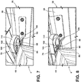
FIG. 7 is a bottom perspective view of a spring finger mounted on a refrigerator door and disengaged from an engagement member mounted on a refrigerator cabinet; and -
FIG. 8 is a bottom perspective view of the spring finger mounted on the refrigerator door ofFIG. 7 and engaged with the engagement member mounted on the refrigerator cabinet. - The components in the figures are not necessarily to scale, emphasis instead being placed upon illustrating the principles described herein.
- The present illustrated embodiments reside primarily in combinations of method steps and apparatus components related to a refrigerator. Accordingly, the apparatus components and method steps have been represented, where appropriate, by conventional symbols in the drawings, showing only those specific details that are pertinent to understanding the embodiments of the present disclosure so as not to obscure the disclosure with details that will be readily apparent to those of ordinary skill in the art having the benefit of the description herein. Further, like numerals in the description and drawings represent like elements.
- For purposes of description herein, the terms "upper," "lower," "right," "left," "rear," "front," "vertical," "horizontal," and derivatives thereof shall relate to the disclosure as oriented in
FIG. 1 . Unless stated otherwise, the term "front" shall refer to the surface of the element closer to an intended viewer, and the term "rear" shall refer to the surface of the element further from the intended viewer. However, it is to be understood that the disclosure may assume various alternative orientations, except where expressly specified to the contrary. It is also to be understood that the specific devices and processes illustrated in the attached drawings, and described in the following specification are simply exemplary embodiments of the inventive concepts defined in the appended claims. Hence, specific dimensions and other physical characteristics relating to the embodiments disclosed herein are not to be considered as limiting, unless the claims expressly state otherwise. - The terms "including," "comprises," "comprising," or any other variation thereof, are intended to cover a non-exclusive inclusion, such that a process, method, article, or apparatus that comprises a list of elements does not include only those elements but may include other elements not expressly listed or inherent to such process, method, article, or apparatus. An element proceeded by "comprises a ..." does not, without more constraints, preclude the existence of additional identical elements in the process, method, article, or apparatus that comprises the element.
- Referring now to
FIG. 1 ,reference numeral 2 general designates a bottom-mount refrigerator for use with the present concept. Therefrigerator 2 includes acabinet 4 having atop wall 6, abottom wall 7, opposingsidewalls rear wall 10 which cooperate to define first andsecond compartments FIG. 1 , thefirst compartment 12 is disposed above thesecond compartment 14. - Referring now to
FIG. 2 , thefirst compartment 12 includes aliner 15 having atop wall 16, abottom wall 17, opposingsidewalls rear wall 20. Afirst guide member 22 is shown disposed on a front portion oftop wall 16 of theliner 15, and asecond guide member 24 is shown disposed on a front potion of thebottom wall 17 of theliner 15. The first andsecond guide members - Although not specifically identified, the
refrigerator 2 is contemplated to include a refrigeration system for providing above and below freezing temperatures incompartments FIG. 1 , it is contemplated that thefirst compartment 12 is a fresh food storage compartment, while thesecond compartment 14 is a freezer compartment. It is further contemplated that the open space configuration of thefirst compartment 12 may include various shelves, drawers and bins for dividing the open space and for storing items to be refrigerated in a manner known in the art. InFIG. 1 , thesecond compartment 14 is selectively accessed via adoor 32, which may be a sliding drawer-style door. Thus, therefrigerator 2 is a bottom mount refrigerator withlower freezer door 32 being adapted to slide in and out of thecabinet 4 to provide access to frozen items stored withinsecond compartment 14. - As further shown in
FIGS. 1 and 2 , therefrigerator 2 includes a French-style door configuration having first andsecond doors second doors cabinet 4 to selectively provide access to thefirst compartment 12. The first andsecond doors open front portion 40 of thecabinet 4 in an air-tight manner to prevent cold air from escaping thefirst compartment 12. Specifically, the first andsecond doors open front portion 40 of thecabinet 4 viaflexible gasket assemblies - As specifically shown in
FIG. 2 , thefirst door 26 includes adoor liner 50 having an outwardly projecting top portion 52, and outwardly projecting first andsecond side portions rear portion 58 interconnects the top portion 52 and the first andsecond side portions storage cavity 60. Within thestorage cavity 60, it is contemplated that a variety of shelf members, i.e. adjustable shelves, bins, storage units and the like, can be positioned within thestorage cavity 60 as supported between the opposingside portions - Except as otherwise identified below, the structure of each of the first and
second doors FIG. 1 , the first andsecond doors inside edges mullion assembly 30 when the first andsecond doors FIG. 1 ). Themullion assembly 30 is a flipper mullion shown in an inwardly rotated or stowed position inFIG. 2 . Movement of themullion assembly 30 is contemplated to be a pivoting movement provided via one or more hinge assemblies interconnecting themullion assembly 30 with thefirst side portion 54 of theliner 50 of thefirst door 26. Movement of themullion assembly 30 between stowed and deployed positions is generally guided by the first andsecond guide members mullion assembly 30 as thefirst door 26 moves to the open position (FIG. 2 ) from a closed position (FIG. 1 ), and vice versa. While themullion assembly 30 is shown coupled to theliner 50 of thefirst door 26, it is also contemplated that themullion assembly 30 can be pivotally mounted to a component part of thesecond door 28, such that the present concept is not limited to a specific right or left door mounting configuration for themullion assembly 30. In the embodiment shown inFIG. 2 , the first andsecond doors cabinet 4 of therefrigerator 2. - Referring now to
FIG. 3 , a fragmentary view of an underside of therefrigerator 2 is shown with thefirst door 26 in a partially open position. The position of thedoor 26 inFIG. 3 will be referred to herein as a first position of thedoor 26 along a swing path of thedoor 26. As shown inFIG. 3 , thedoor 26 includes anunderside 66 having aspring finger assembly 70 fixedly mounted thereto for rotational movement along a swing path of thedoor 26 as indicated byarrow 68. Thedoor 26 is pivotally mounted to thecabinet 4 by anupper hinge assembly 71 as shown inFIGS. 1 and 2 . Thefirst door 26 is further pivotally mounted to thecabinet 4 by alower hinge assembly 72, as shown inFIG. 3 , for pivoting movement of thedoor 26 along the swing path as indicated byarrow 68. Thelower hinge assembly 72 includes ahinge bracket 74 having abody portion 76 which outwardly extends from theopen front portion 40 of thecabinet 4. Thehinge bracket 74 further includes a mountingportion 78 which mounts of thehinge assembly 72 to theopen front portion 40 of thecabinet 4. Thehinge bracket 74 further includes a receivingaperture 80 for receiving ahinge pin 82 which pivotally interconnects thefirst door 26 with thelower hinge assembly 72. Thehinge bracket 74 further includes aninside edge 84 having a laterally extendingengagement member 86. Theengagement member 86 includes first andsecond sides cabinet 4. In this way, theengagement member 86 has a generally wave-shaped profile culminating in adistal end 91. Theengagement member 86 of thehinge bracket 74 is specifically positioned to engage thespring finger assembly 70 as thedoor 26 pivots between open and closed positions relative to thecabinet 4 along theswing path 68 of thedoor 26, as further described below. - As shown in
FIG. 3 , thespring finger assembly 70 includes a mountingportion 100 mounted to theunderside 66 of thefirst door 26 viafasteners 101. Thespring finger assembly 70 further includes a flexiblyresilient spring finger 102 extending outwardly from the mountingportion 100 at aproximal end 104 and curving inwardly to adistal end 106 of thespring finger 102. Thespring finger 102 includes inner andouter edges inner edge 108 is inwardly curved and theouter edge 110 is outwardly curved to provide for an overall inwardly curled configuration of thespring finger 102. - As further shown in
FIG. 3 , theswing path 68 of thedoor 26 indicates a closing motion of the door from the fully open position shown inFIG. 2 towards a fully closed position (shown inFIG. 5 .) With thedoor 26 in a first position along theswing path 68 of thedoor 26, theouter edge 110 of thespring finger 102 is shown as being brought into contact with thefirst side 88 of theengagement member 86 to engage the same. This contact between the resilientlyflexible spring finger 102 and the rigidly mountedengagement member 86 at the first position of thedoor 26 along theswing path 68 of thedoor 26 increases a resistance force on thedoor 26 along theswing path 68 of thedoor 26 at thefirst position 1P shown inFIG. 6 . As used herein, the term "resistance force" is provided to indicate a force imparted on a door in a closing motion of the door. The resistance force will increase as components of the door and refrigerator engage one another, and will decrease as the various engagements cease. - As further shown in
FIG. 3 , themullion assembly 30 includes aguide pin 31 disposed on an underside of themullion assembly 30. Theguide pin 31 is configured to engageguide member 24 of thestorage compartment 12 to rotate themullion assembly 30 along arotational path 33 from the stowed position ofFIG. 3 to a deployed position shown in phantom inFIG. 3 . It is further contemplated that thedoor 26 may include an upper guide pin for engagement with theupper guide member 22 to further guide movement of themullion assembly 30. In the first position of thedoor 26 along theswing path 68 of thedoor 26, thespring finger 102 engages theengagement member 86 to increase a resistance force on thedoor 26, as noted above. However, in the first position of thedoor 26, themullion assembly 30 has not engaged theguide member 24 to further increase the resistance force on the closing motion of thedoor 26. - Referring now to
FIG. 4 , thedoor 26 has moved closer towards the fully closed position shown inFIG. 5 . InFIG. 4 , thedoor 26 is contemplated to be in a second position of thedoor 26 along theswing path 68 of thedoor 26. Thus, the second position of thedoor 26 along the swing path of thedoor 26 is closer to the closed position of thedoor 26 along theswing path 68 of thedoor 26 than the first position of thedoor 26. With thedoor 26 in the second position along theswing path 68 of thedoor 26, theguide pin 31 disposed on the underside of themullion assembly 30 is shown engaging theguide member 24 of thestorage compartment 12. Specifically, theguide pin 31 has engaged aguide path 24A of theguide member 24 at afirst portion 24B thereof. Theguide path 24A of theguide member 24 defines a channel through theguide member 24 that theguide pin 31 of themullion assembly 30 follows to move themullion assembly 30 from the stowed position to the deployed position when closing thedoor 26. Theguide path 24A includes first andsecond portions guide pin 31 of the mullion assembly enters theguide path 24A at thefirst portion 24B of theguide path 24A when initially making contact with theguide member 24 during a door closing movement at the second position of thedoor 26 along the swing path of thedoor 26. This physical engagement, much like the engagement of thespring finger 102 and theengagement member 86, increases the resistance force on thedoor 26 along theswing path 68 of thedoor 26 at thesecond position 2P shown inFIG. 6 , as themullion assembly 30 begins rotation to the deployed position. When themullion assembly 30 is in the deployed position and thedoor 26 is in the fully closed position, as shown inFIG. 5 , theguide pin 31 is disposed in thesecond portion 24C of theguide path 24A of theguide member 24. - As further shown in
FIG. 4 , thedistal end 106 of thespring finger 102 is shown as being brought into contact with thedistal end 91 of theengagement member 86. It is contemplated that a resistance force on thedoor 26 has increased at the engagement of thespring finger 102 and theengagement member 86 from the initial contact at the first position of the door 26 (FIG. 3 ) to the second position of the door 26 (FIG. 4 ). This contact between the resilientlyflexible spring finger 102 and the rigidly mountedengagement member 86 increases the resistance force on thedoor 26 until the closing motion of thedoor 26 overcomes the engagement between theengagement member 86 and thespring finger 102. Thespring finger 102 may flex as thedistal end 106 of thespring finger 102 passes thedistal end 91 of theengagement member 86. The closing motion of thedoor 26 overcomes the engagement between theengagement member 86 and thespring finger 102 at a third position of thedoor 26, indicated byreference numeral 3P inFIG. 6 . The third position of the door 25 is disposed between thesecond position 2P of the door 26 (FIG. 4 ) and the fully closed position FC of the door 26 (FIG. 5 ) along theswing path 68 of thedoor 26. - Referring now to
FIG. 5 ,door 26 is shown in the fully closed position. In the fully closed position of thedoor 26, themullion assembly 30 is in the deployed position with the guide pin disposed in thesecond portion 24C of theguide path 24A of theguide member 24. In the fully closed position, theinner edge 108 of thespring finger 102 engages thesecond side 90 of theengagement member 86 to retain thedoor 26 in the fully closed position. - Referring now to
FIG. 6 , a portion of a closing motion of a door is shown by resistance force 0-10, over time 0-15. The graph ofFIG. 6 is meant to show resistance forces involved in closing a door, such asdoor 26 discussed above. The graph is meant to show increases and decreases in resistance force during a closing motion, but is not meant to indicate a specific force realized on the door, nor a specific closing speed or time to close. In the graph ofFIG. 6 , thedoor 26 is contemplated to be at a fully opened position FO and then afirst position 1P, where the resistance force RF begins to increase. As noted above, the contact between the resilientlyflexible spring finger 102 and the rigidly mountedengagement member 86 at thefirst position 1P of thedoor 26 along theswing path 68 of thedoor 26 increases the resistance force RF realized on thedoor 26. As thedoor 26 moves from thefirst position 1P (shown inFIG. 3 ) to thesecond position 2P (shown inFIG. 4 ) the resistance force RF realized on thedoor 26 further increases. As noted above, themullion assembly 30 engages theguide member 24 at thesecond position 2P of thedoor 26, while thespring finger 102 and theengagement member 86 remain engaged and with one another. Thus, this dual engagement of features acting against the closing motion of thedoor 26 increases the resistance force RF further from thesecond position 2P to thethird position 3P of thedoor 26. At thethird position 3P of thedoor 26, the resistance force RF begins to drop as thespring finger 102 overcomes thedistal end 91 of theengagement member 86. Further, theguide pin 31 of themullion assembly 30 moves towards thesecond portion 24C of theguide path 24A of theguide member 24 at thethird position 3P of thedoor 26 along theswing path 68 of thedoor 26 to decrease resistance. It is further contemplated that themullion assembly 30 can be biased towards the deployed position, such that movement of themullion assembly 30 from thefirst portion 24B of theguide member 24 to thesecond portion 24C of theguide member 24C may further reduce resistance forces given the bias of themullion assembly 30. The drop or decrease in resistance follows from thethird position 3P of thedoor 26 to the fully closed position FC of thedoor 26. - In this way, the
door 26 of the present concept provides for a closing motion wherein a single resistance increase and a single resistance decrease is experienced by the user. In other known assemblies that are not tuned for simultaneous engagement between features of the door, a first resistance increase is felt at the engagement of a spring finger and an engagement member, followed by a first resistance decrease after the spring finger overcomes the engagement member. Then, in other known systems, a second resistance increase is experienced as the mullion assembly engages a guide member, followed by a second resistance decrease as the mullion assembly is deployed. Between such consecutive rising and decreasing forces, a user can leave a refrigerator door ajar, as an initial decrease in resistance can feel like a completed closing motion in terms of tactile feedback to the user. Thus, thedoor 26 of the present concept is tuned or timed to provide a consistent engagement between thespring finger 102 and theengagement member 86, and themullion assembly 30 and theguide member 24 to ensure a singular resistance force increase followed by a singular resistance force decrease when closing thedoor 26. - According to one aspect of the present disclosure, a refrigerator includes a cabinet having a storage compartment with an open front portion. A hinge assembly includes a hinge bracket with an engagement member laterally extending therefrom. A door is pivotally coupled to the open front portion of the storage compartment at the hinge assembly. The door is operable between fully open and fully closed positions along a swing path of the door. The swing path of the door includes a first position of the door that is closer to the fully open position of the door as compared to a second position of the door. A mullion assembly is pivotally coupled to the door and operable between stowed and deployed positions. A guide member is disposed within the storage compartment. The mullion assembly engages the guide member to move the mullion assembly to the deployed position from the stowed position when the door is at the second position along the swing path of the door. A spring finger assembly is operably coupled to the door and includes an inwardly curved spring finger. An outer edge of the spring finger engages the engagement member of the hinge bracket when the door is in the first position along the swing path of the door.
- According to another aspect of the present disclosure, the engagement member of the hinge assembly includes a first side and a second side.
- According to another aspect of the present disclosure, the outer edge of the spring finger engages the first side of the engagement member of the hinge bracket when the door is in the first position along the swing path of the door.
- According to another aspect of the present disclosure, an inner edge of the spring finger engages the second side of the engagement member of the hinge bracket when the door is in the fully closed position along the swing path of the door.
- According to another aspect of the present disclosure, the outer edge of the spring finger engages a distal end of the engagement member of the hinge bracket when the door is in the second position along the swing path of the door.
- According to another aspect of the present disclosure, a force imparted on the door to close the door increases at the first and second positions of the door.
- According to yet another aspect of the present disclosure, the force imparted to close the door decreases at a third position of the door, wherein the third position of the door is positioned between the second position of the door and the fully closed position of the door.
- According to another aspect of the present disclosure, a refrigerator includes a cabinet including a storage compartment with an open front portion. A hinge assembly includes a hinge bracket with an engagement member disposed thereon. A door is pivotally coupled to the open front portion of the storage compartment at the hinge assembly. The door is operable between fully open and fully closed positions along a swing path of the door. The swing path of the door includes a first position of the door and a second position of the door. The second position of the door is closer to the fully closed position of the door as compared to the first position of the door. A mullion assembly is pivotally coupled to the door and operable between stowed and deployed positions. The mullion assembly includes a guide pin. A guide member is disposed within the storage compartment. The guide pin of the mullion assembly engages a first portion of a guide path of the guide member to move the mullion assembly to the deployed position from the stowed position when the door is at the second position along the swing path of the door. A spring finger assembly is operably coupled to the door and includes an inwardly curved spring finger. An outer edge of the spring finger engages the engagement member of the hinge bracket when the door is in the first position along the swing path of the door.
- According to another aspect of the present disclosure, the engagement member of the hinge assembly includes a first side and a second side, and further wherein the outer edge of the spring finger engages the first side of the engagement member of the hinge bracket when the door is in the first position along the swing path of the door.
- According to another aspect of the present disclosure, an inner edge of the spring finger engages the second side of the engagement member of the hinge bracket when the door is in the fully closed position along the swing path of the door.
- According to another aspect of the present disclosure, the outer edge of the spring finger engages a distal end of the engagement member of the hinge bracket when the door is in the second position along the swing path of the door.
- According to another aspect of the present disclosure, the swing path of the door includes a third position of the door positioned between the second position of the door and the fully closed position of the door, and further wherein the guide pin of the mullion assembly is disposed in a second portion of the guide path of the guide member when the door is in the third position.
- According to another aspect of the present disclosure, a resistance force of the door from the fully open position to the closed position increases at the first and second positions of the door.
- According to yet another aspect of the present disclosure, the resistance force of the door decreases from the third position to the fully closed position of the door.
- According to yet another aspect of the present disclosure, a refrigerator includes a door pivotally coupled to a storage compartment between open and closed positions along a swing path of the door. A mullion assembly is coupled to the door. The mullion assembly pivots relative to the door between deployed and stowed positions. An engagement member is coupled to the storage compartment. A spring finger assembly is mounted on the door and includes an inwardly curved spring finger. An outer edge of the spring finger engages the engagement member when the door is in a first position along the swing path of the door. The mullion assembly engages the storage compartment when the door is in a second position that is closer to the closed position of the door as compared to the first position of the door along the swing path thereof.
- According to another aspect of the present disclosure, the outer edge of the spring finger engages a first side of the engagement member when the door is in the second position along the swing path of the door.
- According to another aspect of the present disclosure, the storage compartment includes a guide member having a guide path with first and second portions, and further wherein the mullion assembly engages the first portion of the guide path of the guide member of the storage compartment when the door is in the second position along the swing path of the door.
- According to another aspect of the present disclosure, the swing path of the door includes a third position of the door positioned between the second position of the door and the closed position of the door, and further wherein the mullion assembly engages the second portion of the guide path of the guide member when the door is in the third position.
- According to another aspect of the present disclosure, the spring finger overcomes a distal end of the engagement member when the door is in the third position.
- According to yet another aspect of the present disclosure, an inner edge of the spring finger engages a second side of the engagement member when the door is in the closed position along the swing path of the door.
- According to one aspect of the present disclosure, a refrigerator includes a door pivotally coupled to a storage compartment between open and closed positions along a swing path of the door. A mullion assembly is coupled to the door and pivots relative to the door between deployed and stowed positions. An engagement member is coupled to the storage compartment. A spring finger assembly is mounted on the door and includes a spring finger. An outer edge of the spring finger engages the engagement member when the door is in a first position along the swing path of the door. The mullion assembly engages the storage compartment when the door is in a second position that is closer to the closed position of the door as compared to the first position of the door along the swing path of the door. A resistance force of the door from the open position to the closed position increases from the first position of the door to the second position of the door.
- According to another aspect of the present disclosure, the outer edge of the spring finger engages a first side of the engagement member when the door is in the second position along the swing path of the door.
- According to another aspect of the present disclosure, the storage compartment includes a guide member having a guide path defined therein. The guide path includes first and second portions.
- According to another aspect of the present disclosure, the mullion assembly includes an outwardly extending guide pin that is received in the first portion of the guide path of the guide member when the door is in the second position along the swing path of the door.
- According to another aspect of the present disclosure, the swing path of the door includes a third position of the door positioned between the second position of the door and the closed position of the door. The guide pin of the mullion assembly is received in the second portion of the guide path of the guide member when the door is in the third position.
- According to another aspect of the present disclosure, the guide path of the guide member guides the mullion assembly from the stowed position to the deployed position as the guide pin of the mullion assembly moves from the first portion of the guide path of the guide member to the second portion of the guide path of the guide member.
- According to another aspect of the present disclosure, the spring finger overcomes a distal end of the engagement member when the door is in the third position.
- According to another aspect of the present disclosure, an inner edge of the spring finger engages a second side of the engagement member when the door is in the closed position along the swing path of the door.
- According to another aspect of the present disclosure, the resistance force decreases from the second position to the third position of the door.
- According to another aspect of the present disclosure, the inner edge is inwardly curved and the outer edge is outwardly curved to provide for an overall inwardly curled configuration of the spring finger.
- According to another aspect of the present disclosure, a hinge assembly having a hinge bracket. The engagement member laterally extends from the hinge bracket.
- According to another aspect of the present disclosure, the outer edge of the spring finger engages a distal end of the engagement member of the hinge bracket when the door is in the second position along the swing path of the door.
- According to another aspect of the present disclosure, the spring finger overcomes the distal end of the engagement member when the door moves from the second position to the third position along the swing path of the door.
- According to yet another aspect of the present disclosure, the spring finger is flexibly resilient.
Claims (14)
- A refrigerator (2), comprising:a door (26) pivotally coupled to a storage compartment (12) between open and closed positions along a swing path (68) of the door (26);a mullion assembly (30) coupled to the door (26), wherein the mullion assembly (30) pivots relative to the door (26) between deployed and stowed positions;an engagement member (86) coupled to the storage compartment (12); anda spring finger assembly (70) mounted on the door (26) and having a spring finger (102), wherein an outer edge (110) of the spring finger (102) engages the engagement member (86) when the door (26) is in a first position along the swing path (68) of the door (26), and further wherein the mullion assembly (30) engages the storage compartment (12) when the door (26) is in a second position that is closer to the closed position of the door (26) as compared to the first position of the door (26) along the swing path (68) of the door (26), wherein a resistance force (RF) of the door (26) from the open position to the closed position increases from the first position of the door to the second position of the door (26).
- The refrigerator (2) of claim 1, wherein the outer edge (110) of the spring finger (102) engages a first side (88) of the engagement member (86) when the door (26) is in the second position along the swing path (68) of the door (26).
- The refrigerator (2) of claim 2, wherein the storage compartment (12) includes a guide member (24) having a guide path (24A) defined therein, wherein the guide path (24A) includes first and second portions (24B, 24C).
- The refrigerator (2) of claim 3, wherein the mullion assembly (30) includes an outwardly extending guide pin (31) that is received in the first portion (24B) of the guide path (24A) of the guide member (24) when the door (26) is in the second position along the swing path (68) of the door (26).
- The refrigerator (2) of claim 4, wherein the swing path (68) of the door (26) includes a third position of the door (26) positioned between the second position of the door (26) and the closed position of the door (26), and further wherein the guide pin (31) of the mullion assembly (30) is received in the second portion (24C) of the guide path (24A) of the guide member (24) when the door (26) is in the third position.
- The refrigerator (2) of claim 5, wherein the guide path (24A) of the guide member (24) guides the mullion assembly (30) from the stowed position to the deployed position as the guide pin (31) of the mullion assembly (30) moves from the first portion (24B) of the guide path (24A) of the guide member (24) to the second portion (24C) of the guide path (24A) of the guide member (24).
- The refrigerator (2) of any one of claims 5 and 6, wherein the spring finger (102) overcomes a distal end (91) of the engagement member (86) when the door (26) is in the third position.
- The refrigerator (2) of claim 7, wherein an inner edge (108) of the spring finger (102) engages a second side (90) of the engagement member (86) when the door (26) is in the closed position along the swing path (68) of the door (26).
- The refrigerator (2) of any one of claims 5-8, wherein the resistance force (RF) decreases from the second position to the third position of the door (26).
- The refrigerator (2) of any one of claims 8 and 9, wherein the inner edge (108) is inwardly curved and the outer edge (110) is outwardly curved to provide for an overall inwardly curled configuration of the spring finger (102).
- The refrigerator (2) of claim 1, including:
a hinge assembly (72) having a hinge bracket (74), wherein the engagement member (86) laterally extends from the hinge bracket (74). - The refrigerator (2) of claim 11, wherein the outer edge (110) of the spring finger (102) engages a distal end (91) of the engagement member (86) of the hinge bracket (74) when the door (26) is in the second position along the swing path (68) of the door (26).
- The refrigerator (2) of claim 12, wherein the spring finger (102) overcomes the distal end (91) of the engagement member (86) when the door (26) moves from the second position to the third position along the swing path (68) of the door (26).
- The refrigerator (2) of any one of claims 1-13, wherein the spring finger (102) is flexibly resilient.
Applications Claiming Priority (1)
| Application Number | Priority Date | Filing Date | Title |
|---|---|---|---|
| US201916553867A | 2019-08-28 | 2019-08-28 |
Publications (1)
| Publication Number | Publication Date |
|---|---|
| EP3786555A1 true EP3786555A1 (en) | 2021-03-03 |
Family
ID=72087887
Family Applications (1)
| Application Number | Title | Priority Date | Filing Date |
|---|---|---|---|
| EP20191012.2A Withdrawn EP3786555A1 (en) | 2019-08-28 | 2020-08-13 | Refrigerator door with timed spring finger assembly |
Country Status (2)
| Country | Link |
|---|---|
| EP (1) | EP3786555A1 (en) |
| CN (1) | CN112444044A (en) |
Citations (3)
| Publication number | Priority date | Publication date | Assignee | Title |
|---|---|---|---|---|
| CN103851862A (en) * | 2014-03-24 | 2014-06-11 | 海信容声(广东)冰箱有限公司 | Refrigerator |
| EP2741034A2 (en) * | 2012-12-10 | 2014-06-11 | LG Electronics, Inc. | Refrigerator |
| CN107940880A (en) * | 2017-12-12 | 2018-04-20 | 海信容声(广东)冰箱有限公司 | It is a kind of to have the function of to help the refrigerator door articulated structure and refrigerator inhaled |
-
2020
- 2020-08-07 CN CN202010790709.1A patent/CN112444044A/en active Pending
- 2020-08-13 EP EP20191012.2A patent/EP3786555A1/en not_active Withdrawn
Patent Citations (3)
| Publication number | Priority date | Publication date | Assignee | Title |
|---|---|---|---|---|
| EP2741034A2 (en) * | 2012-12-10 | 2014-06-11 | LG Electronics, Inc. | Refrigerator |
| CN103851862A (en) * | 2014-03-24 | 2014-06-11 | 海信容声(广东)冰箱有限公司 | Refrigerator |
| CN107940880A (en) * | 2017-12-12 | 2018-04-20 | 海信容声(广东)冰箱有限公司 | It is a kind of to have the function of to help the refrigerator door articulated structure and refrigerator inhaled |
Also Published As
| Publication number | Publication date |
|---|---|
| CN112444044A (en) | 2021-03-05 |
Similar Documents
| Publication | Publication Date | Title |
|---|---|---|
| US7008032B2 (en) | Refrigerator incorporating french doors with rotating mullion bar | |
| EP3330648B1 (en) | Refrigerator | |
| US9243839B2 (en) | Refrigerator | |
| KR101655801B1 (en) | Closing and opening device for refrigerator door | |
| EP3786556A1 (en) | Mullion hinge assembly | |
| US20110095670A1 (en) | Automatic door closing device of refrigerator and refrigerator having the same | |
| US20080203739A1 (en) | Mixed type refrigerator with unit to keep doors closed | |
| EP1903288A2 (en) | Drawer Type Door and Refrigerator having the Same | |
| US20110132024A1 (en) | Refrigerator having door opening apparatus | |
| US9310126B2 (en) | Refrigerator | |
| KR101741392B1 (en) | Refrigerator comprising shelf which is automatically drawn out | |
| US8549872B2 (en) | Refrigerator | |
| KR101578354B1 (en) | Closing and opening device for refrigerator door | |
| JP3380492B2 (en) | Refrigerator storage container | |
| KR101098732B1 (en) | Refrigerator and shelf assembly for the rerfigerator | |
| KR20140134865A (en) | Refrigerator | |
| KR20160018172A (en) | Apparatus for fixing door and refrigerator having the same | |
| JP4219346B2 (en) | refrigerator | |
| KR101659957B1 (en) | Refrigerator having sliding door | |
| EP3779336B1 (en) | Refrigerator | |
| CN112444044A (en) | refrigerator | |
| KR20150142221A (en) | Refrigerator and shelf assembly applying the same | |
| KR20160091872A (en) | Closing and opening device for refrigerator door | |
| JP7560111B2 (en) | refrigerator | |
| JP2017172826A (en) | refrigerator |
Legal Events
| Date | Code | Title | Description |
|---|---|---|---|
| PUAI | Public reference made under article 153(3) epc to a published international application that has entered the european phase |
Free format text: ORIGINAL CODE: 0009012 |
|
| STAA | Information on the status of an ep patent application or granted ep patent |
Free format text: STATUS: THE APPLICATION HAS BEEN PUBLISHED |
|
| AK | Designated contracting states |
Kind code of ref document: A1 Designated state(s): AL AT BE BG CH CY CZ DE DK EE ES FI FR GB GR HR HU IE IS IT LI LT LU LV MC MK MT NL NO PL PT RO RS SE SI SK SM TR |
|
| AX | Request for extension of the european patent |
Extension state: BA ME |
|
| STAA | Information on the status of an ep patent application or granted ep patent |
Free format text: STATUS: REQUEST FOR EXAMINATION WAS MADE |
|
| 17P | Request for examination filed |
Effective date: 20210809 |
|
| RBV | Designated contracting states (corrected) |
Designated state(s): AL AT BE BG CH CY CZ DE DK EE ES FI FR GB GR HR HU IE IS IT LI LT LU LV MC MK MT NL NO PL PT RO RS SE SI SK SM TR |
|
| STAA | Information on the status of an ep patent application or granted ep patent |
Free format text: STATUS: THE APPLICATION HAS BEEN WITHDRAWN |
|
| 18W | Application withdrawn |
Effective date: 20220510 |