EP3786490A1 - Improved lubrication system for a drivetrain of a vehicle - Google Patents
Improved lubrication system for a drivetrain of a vehicle Download PDFInfo
- Publication number
- EP3786490A1 EP3786490A1 EP20193245.6A EP20193245A EP3786490A1 EP 3786490 A1 EP3786490 A1 EP 3786490A1 EP 20193245 A EP20193245 A EP 20193245A EP 3786490 A1 EP3786490 A1 EP 3786490A1
- Authority
- EP
- European Patent Office
- Prior art keywords
- lubrication
- oil
- vehicle
- drivetrain
- operative condition
- Prior art date
- Legal status (The legal status is an assumption and is not a legal conclusion. Google has not performed a legal analysis and makes no representation as to the accuracy of the status listed.)
- Granted
Links
Images


Classifications
-
- F—MECHANICAL ENGINEERING; LIGHTING; HEATING; WEAPONS; BLASTING
- F16—ENGINEERING ELEMENTS AND UNITS; GENERAL MEASURES FOR PRODUCING AND MAINTAINING EFFECTIVE FUNCTIONING OF MACHINES OR INSTALLATIONS; THERMAL INSULATION IN GENERAL
- F16H—GEARING
- F16H57/00—General details of gearing
- F16H57/04—Features relating to lubrication or cooling or heating
- F16H57/0412—Cooling or heating; Control of temperature
-
- F—MECHANICAL ENGINEERING; LIGHTING; HEATING; WEAPONS; BLASTING
- F16—ENGINEERING ELEMENTS AND UNITS; GENERAL MEASURES FOR PRODUCING AND MAINTAINING EFFECTIVE FUNCTIONING OF MACHINES OR INSTALLATIONS; THERMAL INSULATION IN GENERAL
- F16H—GEARING
- F16H57/00—General details of gearing
- F16H57/04—Features relating to lubrication or cooling or heating
- F16H57/0434—Features relating to lubrication or cooling or heating relating to lubrication supply, e.g. pumps; Pressure control
- F16H57/0445—Features relating to lubrication or cooling or heating relating to lubrication supply, e.g. pumps; Pressure control for supply of different gearbox casings or sections
-
- F—MECHANICAL ENGINEERING; LIGHTING; HEATING; WEAPONS; BLASTING
- F16—ENGINEERING ELEMENTS AND UNITS; GENERAL MEASURES FOR PRODUCING AND MAINTAINING EFFECTIVE FUNCTIONING OF MACHINES OR INSTALLATIONS; THERMAL INSULATION IN GENERAL
- F16H—GEARING
- F16H61/00—Control functions within control units of change-speed- or reversing-gearings for conveying rotary motion ; Control of exclusively fluid gearing, friction gearing, gearings with endless flexible members or other particular types of gearing
- F16H61/0021—Generation or control of line pressure
- F16H61/0025—Supply of control fluid; Pumps therefor
-
- F—MECHANICAL ENGINEERING; LIGHTING; HEATING; WEAPONS; BLASTING
- F16—ENGINEERING ELEMENTS AND UNITS; GENERAL MEASURES FOR PRODUCING AND MAINTAINING EFFECTIVE FUNCTIONING OF MACHINES OR INSTALLATIONS; THERMAL INSULATION IN GENERAL
- F16H—GEARING
- F16H61/00—Control functions within control units of change-speed- or reversing-gearings for conveying rotary motion ; Control of exclusively fluid gearing, friction gearing, gearings with endless flexible members or other particular types of gearing
- F16H61/02—Control functions within control units of change-speed- or reversing-gearings for conveying rotary motion ; Control of exclusively fluid gearing, friction gearing, gearings with endless flexible members or other particular types of gearing characterised by the signals used
- F16H61/0262—Control functions within control units of change-speed- or reversing-gearings for conveying rotary motion ; Control of exclusively fluid gearing, friction gearing, gearings with endless flexible members or other particular types of gearing characterised by the signals used the signals being hydraulic
- F16H61/0265—Control functions within control units of change-speed- or reversing-gearings for conveying rotary motion ; Control of exclusively fluid gearing, friction gearing, gearings with endless flexible members or other particular types of gearing characterised by the signals used the signals being hydraulic for gearshift control, e.g. control functions for performing shifting or generation of shift signals
- F16H61/0267—Layout of hydraulic control circuits, e.g. arrangement of valves
-
- F—MECHANICAL ENGINEERING; LIGHTING; HEATING; WEAPONS; BLASTING
- F16—ENGINEERING ELEMENTS AND UNITS; GENERAL MEASURES FOR PRODUCING AND MAINTAINING EFFECTIVE FUNCTIONING OF MACHINES OR INSTALLATIONS; THERMAL INSULATION IN GENERAL
- F16H—GEARING
- F16H59/00—Control inputs to control units of change-speed- or reversing-gearings for conveying rotary motion
- F16H59/36—Inputs being a function of speed
- F16H2059/366—Engine or motor speed
-
- F—MECHANICAL ENGINEERING; LIGHTING; HEATING; WEAPONS; BLASTING
- F16—ENGINEERING ELEMENTS AND UNITS; GENERAL MEASURES FOR PRODUCING AND MAINTAINING EFFECTIVE FUNCTIONING OF MACHINES OR INSTALLATIONS; THERMAL INSULATION IN GENERAL
- F16H—GEARING
- F16H59/00—Control inputs to control units of change-speed- or reversing-gearings for conveying rotary motion
- F16H59/74—Inputs being a function of engine parameters
- F16H2059/746—Engine running state, e.g. on-off of ignition switch
-
- F—MECHANICAL ENGINEERING; LIGHTING; HEATING; WEAPONS; BLASTING
- F16—ENGINEERING ELEMENTS AND UNITS; GENERAL MEASURES FOR PRODUCING AND MAINTAINING EFFECTIVE FUNCTIONING OF MACHINES OR INSTALLATIONS; THERMAL INSULATION IN GENERAL
- F16H—GEARING
- F16H57/00—General details of gearing
- F16H57/04—Features relating to lubrication or cooling or heating
- F16H57/0434—Features relating to lubrication or cooling or heating relating to lubrication supply, e.g. pumps; Pressure control
- F16H57/0441—Arrangements of pumps
Definitions
- electronic control unit 8 will act on both the single pump 11 and on each valve 12, thereby allowing the sucking of oil from source 3 and pumping towards the specific lubrication point/s 5.
- the proposed lubrication system is furthermore compact and save the use of great oil quantity, thereby further reducing vehicle's consumption.
Landscapes
- Engineering & Computer Science (AREA)
- General Engineering & Computer Science (AREA)
- Mechanical Engineering (AREA)
- General Details Of Gearings (AREA)
Abstract
Description
- The present invention concerns a lubrication system for a drivetrain of a vehicle, in particular a lubrication system for a drivetrain of a work vehicle such as an agricultural vehicle.
- Drivetrain of a vehicle needs to be continuously lubricated in order to guarantee a proper operation of the same. In particular, such need is even more felt in case of an agricultural vehicle because of the great loads transmitted through the drivetrain components.
- As known, existent lubrication systems comprises a pump configured to provide oil on the drivetrain, e.g. by spraying lubricating oil on the top of the drivetrain.
- The operation of such pump may be controlled depending on a plurality of different variables such as the speed of the vehicle or the operation of the engine carrying the drivetrain etc. Usually, lubrication pump is directly carried by the engine and therefore its operation strictly depends on the engine's speed.
- However, it is clear that the pump will provide always a great quantity of oil to all the drivetrain components even if the critical components of the drivetrain that needs lubrication are fewer, e.g. specific gearing.
- Accordingly, the power consumption of such pump is not negligible and affects the fuel consumption of the vehicle.
- Therefore, the need is felt to reduce the power consumption of existing lubrication systems for drivetrains while, at the same time, guaranteeing a correct lubrication of each component of the drivetrain.
- An aim of the present invention is to satisfy the above mentioned needs in a compact, cost-effective and optimized way.
- The aforementioned aim is reached by a lubrication system as claimed in the appended set of claims.
- For a better understanding of the present invention, a preferred embodiment is described in the following, by way of a non-limiting example, with reference to the attached drawings wherein:
-
Figure 1 is a schematic perspective view of a lubrication system according a first embodiment of the present invention; -
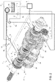
Figure 2 is a schematic perspective view of a lubrication system according a second embodiment of the present invention; and -
Figure 3 is a flow-chart illustrating a control method for the lubrication system according to the present invention. -
Figure 1 discloses a lubrication system 1 for adrivetrain 2 of a vehicle (not shown). The drivetrain, as known, may comprise a plurality of elements such asgears 2a,bearings 2b andshafts 2c. Since the objective of the present invention is not linked to a peculiar structure ofsuch drivetrain 2, this latter will be not described further in detail for sake of brevity. - Lubrication system 1 further comprises an
oil source 3, e.g. a reservoir configured to store a sufficient quantity of transmission oil, as known. - According to the invention, lubrication system 1 comprises a plurality of
lubrication points 5 each voted to provide oil to aspecific component drivetrain 2 according a predefined operative condition ofdrivetrain 2 and, preferably, of the vehicle. - In the proposed embodiments of
figures 1 and2 thelubrication points 5 are each directed to abearing 2b ofdrivetrain 2 and comprises essentially a nozzle directed to provide oil from the top of such component. However it is clear that such representation is merely schematic and different way and disposition to provide oil tocomponents drivetrain 2 may be provided. - Each
lubrication point 5 is then fluidly connected by arespective conduit 6 tooil source 3 to allow oil feeding. - Lubrication system 1 comprises a plurality of sensor means 7 configured to detect a temperature of the element which is lubricated by the
lubrication point 5. Accordingly, sensor means 7 are temperature sensors and may comprise any typology of sensor, e.g. an infrared camera. - Lubrication system 1 further comprises an
electronic control unit 8 that is electrically connected, e.g. via wire or electromagnetically, to each of the aforementioned sensor means 7 and it is configured to acquire the value of temperature detected by thesensors 7.Electronic control unit 8 is furthermore configured to acquire vehicle operation quantities, e.g. vehicle's velocity, engine's rpm or engine's working time e.g. via CAN-BUS connection. Preferably theaforementioned control unit 8 is the ECU of the vehicle. - According to the invention,
electronic control unit 8 is configured to acquire the temperature values detected by sensor means 7 and, preferably, operational values of the vehicle and control thelubrication points 5 to selectively provide oil, when needed and to a specific point of the driveline. A proposed method of control will be described further. - In the first embodiment of
figure 1 ,lubrication system 2 comprises, for eachlubrication point 5, apump 9 fluidly interposed on therespective conduit 6 and configured to suck oil fromsource 3 and increase its pressure to allow its ejection fromlubrication point 5 towardsdrivetrain 2. - Each
pump 9 is electrically connected toelectronic control unit 8 and controlled by this latter to provide oil to therespective lubrication point 5. - In the second embodiment of
figure 2 ,lubrication system 2 comprises asingle pump 11 fluidly interposed between eachlubrication point 5 andoil source 3. Accordingly, each lubrication point is fluidly connected by aconduit 6a to pump 11 and this latter is fluidly connected by asingle conduit 6b tooil source 3. - According to such embodiment, lubrication system comprises a
valve 12 for eachconduit 6a configured to allow or deny the passage of oil frompump 11 to therelated lubrication point 5. - Advantageously,
valves 12 are electrically controlled valves and eachvalve 12 is electrically connected to theelectronic control unit 8 and controlled by this latter to provide oil to therespective lubrication point 5. - The operation of the lubrication system 1 according to the preceding described embodiments is the following.
- When the temperature detected by sensor means 7 of a specific point of the
drivetrain 2 overcomes a preset threshold, thenelectronic control unit 8 will act consequently to provide oil to only therelated lubrication point 5. In particular,electronic control unit 8 will control the quantity of oil flow which needs to be imparted to such lubrication point. - In the embodiment of
figure 1 ,electronic control unit 8 will act directly on eachpump 9, thereby allowing the sucking of oil fromsource 3 and pumping towards the specific lubrication point/s 5. - In the embodiment of
figure 2 ,electronic control unit 8 will act on both thesingle pump 11 and on eachvalve 12, thereby allowing the sucking of oil fromsource 3 and pumping towards the specific lubrication point/s 5. - According to the above, the present invention is also related to a method for controlling a lubrication system, preferably as described above.
- Such method will be described referring to the schematic shown in
figure 3 ; therefore the method comprises essentially the following phases: - Verifying (I) that a preset operative condition based on a temperature of a point of the
drivetrain 2 is reached; - If such preset operative condition is reached, then providing (II) oil to the lubrication point/
s 5; - Verifying (III) that the preset operative condition is maintained;
- If such present operative condition is maintained, then keep providing (IV) oil to the to the lubrication point/
s 5 and coming back to point (III); and - Otherwise, if such present operative condition is not maintained, then stop providing (V) oil to the to the lubrication point/
s 5 and coming back to point (I). - The preset operative condition of the vehicle comprises at least the control that the temperature of a point of the drivetrain is greater than a preset threshold temperature.
- Preferably, the preset operative condition of the vehicle comprises also the control that velocity of the engine is greater than a preset threshold velocity.
- More preferably, the preset operative condition of the vehicle comprises also the control that engine is in operation for a time greater than a preset threshold time.
- Obviously, the phase of providing oil may be actuated in different ways according to the embodiment of
lubrication point 5 and related hydraulic circuit keeping oil fromsource 3 towards this latter. - The
electronic control unit 9 advantageously comprise elaboration means configured to elaborate the phases of the above disclosed method. - In view of the foregoing, the advantages of a lubrication system 1 and a related method according to the invention are apparent.
- Thanks to the proposed lubrication system, it is possible to avoid a continuous use of a big pump to provide oil to the
entire driveline 2. Indeed, in both exemplarily described embodiments, oil is given todriveline 2 only when and where needed. Accordingly, power is saved and vehicle's consumption is reduced. - Furthermore, the use of thermic sensors means 7 on specific dangerous points allows monitoring continuously such points, thereby improving the lifetime of the
driveline 2. - Furthermore, since oil is pumped directly on such points, their temperature is constantly maintained in a safe working range, thereby improving oil quality over time.
- The use of
electronic pumps 9 or ofvalves 12 allows to quick and easily control the operation of the system 1 and to design it according to the specific use of the vehicle. Indeed, even though temperature of specific points of thedriveline 2 will be a constant present monitored value, other parameters of work vehicle operation may be included in the claimed method. - The proposed lubrication system is furthermore compact and save the use of great oil quantity, thereby further reducing vehicle's consumption.
- It is clear that modifications can be made to the described lubrication system 1 and a related method that do not extend beyond the scope of protection defined by the claims.
- For example, it is clear that the lubrication points 5 may be varied according to the dimensions and typology of point to be lubricated.
- Furthermore, it is clear that other electro-hydraulic systems to provide oil to
lubrication points 5, different with respect to the two described embodiments. - Obviously, other typology of temperature sensor means may be used instead of the described one.
- Again, other quantities related to different working operations of the
driveline 2 or of the vehicle may be used in combination or substitution of the described one by theelectronic control unit 8 as predefined operative condition.
Claims (14)
- Lubrication system (1) for lubricating a drivetrain (2) of a work vehicle said system (1) comprising a plurality of lubrication points (5) each fluidly connectable to a source (3) of oil of said vehicle and configured to provide oil to a specific point of said drivetrain (2) and sensor means (7) configured to detect a temperature value of said specific point, said system (1) further comprises an electronic control unit (8) electrically connected to said sensor means (7) and configured to acquire the temperature value detected by said sensor means, said electronic control unit (8) being further configured to allow the passage of oil from said source (3) to said lubrication points (5) according to a predefined condition based on said acquired temperature value.
- Lubrication system according to claim 1, wherein said specific point is on a single element (2a, 2b, 2c) of said drivetrain (2).
- Lubrication system according to claim 1 or 2, wherein said sensor means (7) comprises an infrared camera.
- Lubrication system according to any of claims 1 to 3, further comprising a pump (9) for each of said lubrication points (5), said pumps (9) being interposed between the respective lubrication point (5) and the source (3) of oil and being configured to suck oil from said source (3) and pumping it to said lubrication point (5) under control of said electronic control unit (8).
- Lubrication system according to any of claims 1 to 3, further comprising a single pump (11) for all of said lubrication points (5), said pump (11) being interposed between said plurality of lubrication points (5) and the source (3) of oil and being configured to suck oil from said source (3) and pumping towards said points (5), said lubrication system (1) further comprising a valve (12) for each of said lubrication points (5), said valves (12) being interposed between the respective lubrication point (5) and said single pump (11) and configured for allowing the passage of oil pumped by said single pump (11) towards said lubrication points (5) under control of said electronic control unit (8).
- Lubrication system according to claim 5, wherein said valves (12) are electrical valve connected and controlled by said control unit (8).
- Lubrication system according to claim 4, wherein said pumps (9, 11) are electrical pumps connected and controlled by said control unit (8).
- Lubrication system according to any of the preceding claims, wherein said predefined operative condition comprises the fact that the acquired temperature by said sensor means (7) is greater than a preset threshold temperature memorized by said electronic control unit.
- Lubrication system according to claim 8, wherein said preset operative condition of the vehicle comprises controlling that the velocity of the engine of said vehicle is greater than a preset threshold velocity.
- Lubrication system according to claim 8 or 9, wherein said preset operative condition of the vehicle comprises controlling that the engine of said vehicle is in operation for a time greater than a preset threshold time.
- Method for lubricating a drivetrain (2) by means of a lubrication system according to any of the preceding claims and comprising the following steps:• (I) Verifying that a preset operative condition based on a temperature of a point of said drivetrain (2) is reached;• (II) If such preset operative condition is reached, then providing oil to said lubrication points (5);• (III) Verifying that the preset operative condition is maintained;• (IV) If such present operative condition is maintained, then keep providing oil to the to the lubrication points (5) and coming back to step III; and• (V) Otherwise, if such present operative condition is not maintained, then stop providing oil to said lubrication points (5) and coming back to step I.
- Method according to claim 11, wherein said preset operative condition comprises controlling that the temperature of a point of said drivetrain (2) is greater than a preset threshold temperature.
- Method according to claim 12, wherein said preset operative condition of the vehicle comprises controlling that the velocity of the engine of said vehicle is greater than a preset threshold velocity.
- Method according to claim 12 or 13, wherein said preset operative condition of the vehicle comprises controlling that the engine of said vehicle is in operation for a time greater than a preset threshold time.
Applications Claiming Priority (1)
| Application Number | Priority Date | Filing Date | Title |
|---|---|---|---|
| IT102019000015129A IT201900015129A1 (en) | 2019-08-28 | 2019-08-28 | IMPROVED LUBRICATION SYSTEM FOR A VEHICLE TRANSMISSION |
Publications (2)
| Publication Number | Publication Date |
|---|---|
| EP3786490A1 true EP3786490A1 (en) | 2021-03-03 |
| EP3786490B1 EP3786490B1 (en) | 2023-10-25 |
Family
ID=68988218
Family Applications (1)
| Application Number | Title | Priority Date | Filing Date |
|---|---|---|---|
| EP20193245.6A Active EP3786490B1 (en) | 2019-08-28 | 2020-08-28 | Improved lubrication system for a drivetrain of a vehicle |
Country Status (2)
| Country | Link |
|---|---|
| EP (1) | EP3786490B1 (en) |
| IT (1) | IT201900015129A1 (en) |
Citations (4)
| Publication number | Priority date | Publication date | Assignee | Title |
|---|---|---|---|---|
| JP2002147584A (en) * | 2000-11-10 | 2002-05-22 | Toyota Motor Corp | Automotive drive units |
| JP2007085397A (en) * | 2005-09-20 | 2007-04-05 | Toyota Motor Corp | Cooling lubrication device for powertrain equipment for vehicles |
| JP2010126047A (en) * | 2008-11-28 | 2010-06-10 | Aisin Aw Co Ltd | Driving device for hybrid car |
| US20180045295A1 (en) * | 2016-08-12 | 2018-02-15 | Toyota Jidosha Kabushiki Kaisha | Lubricating apparatus of vehicle |
-
2019
- 2019-08-28 IT IT102019000015129A patent/IT201900015129A1/en unknown
-
2020
- 2020-08-28 EP EP20193245.6A patent/EP3786490B1/en active Active
Patent Citations (4)
| Publication number | Priority date | Publication date | Assignee | Title |
|---|---|---|---|---|
| JP2002147584A (en) * | 2000-11-10 | 2002-05-22 | Toyota Motor Corp | Automotive drive units |
| JP2007085397A (en) * | 2005-09-20 | 2007-04-05 | Toyota Motor Corp | Cooling lubrication device for powertrain equipment for vehicles |
| JP2010126047A (en) * | 2008-11-28 | 2010-06-10 | Aisin Aw Co Ltd | Driving device for hybrid car |
| US20180045295A1 (en) * | 2016-08-12 | 2018-02-15 | Toyota Jidosha Kabushiki Kaisha | Lubricating apparatus of vehicle |
Also Published As
| Publication number | Publication date |
|---|---|
| IT201900015129A1 (en) | 2021-02-28 |
| EP3786490B1 (en) | 2023-10-25 |
Similar Documents
| Publication | Publication Date | Title |
|---|---|---|
| US8347618B2 (en) | Dual pump hydraulic system | |
| EP1881222B1 (en) | Method of operating a dual clutch transmission hydraulic power control system as well as dual clutch transmission hydraulic power control system | |
| US9115736B2 (en) | Work vehicle fluid heating system | |
| US9650925B2 (en) | System and method of augmenting low oil pressure in an internal combustion engine | |
| US20080179158A1 (en) | Hydraulic double clutch | |
| US7954317B2 (en) | Hydraulic system | |
| EP3012489B1 (en) | Hydraulic system for a vehicle | |
| US11668389B2 (en) | Hydraulic arrangement for a vehicle transmission | |
| EP2758672B1 (en) | Oil level control device | |
| KR20130109323A (en) | Oil pump control system for vehicle and operation method thereof | |
| US9709159B2 (en) | Method for controlling the transfer of torque of a force-fitting shift element | |
| US7958983B2 (en) | Hydraulic system in motor vehicles | |
| CN109084015B (en) | Method for operating a hydraulic system for an automatic transmission and control system | |
| WO2016071411A1 (en) | Hydraulic pressure supply system | |
| US7802971B2 (en) | Controller for a variable displacement feed pump | |
| US20120006432A1 (en) | Hydraulic Circuit Supply System | |
| EP3786490B1 (en) | Improved lubrication system for a drivetrain of a vehicle | |
| US6889634B1 (en) | Method of providing hydraulic pressure for mechanical work from an engine lubricating system | |
| US12169017B2 (en) | Vehicle transmission with a power take-off, vehicle and working machine arrangement | |
| US12241483B2 (en) | Method for the open-loop control of a pump system | |
| US9599127B2 (en) | Hydraulic circuit supply system | |
| JP2008267444A (en) | Transmission device equipped with hydraulic pressure control mechanism | |
| US20190170246A1 (en) | Hydrostatic drive having a closed circuit and method for operating the drive | |
| US20180100577A1 (en) | Multi-pressure hydraulic control system for a dual clutch automatic transmission | |
| US11199115B2 (en) | Oil system and method of controlling oil system |
Legal Events
| Date | Code | Title | Description |
|---|---|---|---|
| PUAI | Public reference made under article 153(3) epc to a published international application that has entered the european phase |
Free format text: ORIGINAL CODE: 0009012 |
|
| STAA | Information on the status of an ep patent application or granted ep patent |
Free format text: STATUS: THE APPLICATION HAS BEEN PUBLISHED |
|
| AK | Designated contracting states |
Kind code of ref document: A1 Designated state(s): AL AT BE BG CH CY CZ DE DK EE ES FI FR GB GR HR HU IE IS IT LI LT LU LV MC MK MT NL NO PL PT RO RS SE SI SK SM TR |
|
| AX | Request for extension of the european patent |
Extension state: BA ME |
|
| STAA | Information on the status of an ep patent application or granted ep patent |
Free format text: STATUS: REQUEST FOR EXAMINATION WAS MADE |
|
| 17P | Request for examination filed |
Effective date: 20210903 |
|
| RBV | Designated contracting states (corrected) |
Designated state(s): AL AT BE BG CH CY CZ DE DK EE ES FI FR GB GR HR HU IE IS IT LI LT LU LV MC MK MT NL NO PL PT RO RS SE SI SK SM TR |
|
| RIC1 | Information provided on ipc code assigned before grant |
Ipc: F16H 61/02 20060101ALI20230217BHEP Ipc: F16H 61/00 20060101ALI20230217BHEP Ipc: F16H 57/04 20060101AFI20230217BHEP |
|
| GRAP | Despatch of communication of intention to grant a patent |
Free format text: ORIGINAL CODE: EPIDOSNIGR1 |
|
| STAA | Information on the status of an ep patent application or granted ep patent |
Free format text: STATUS: GRANT OF PATENT IS INTENDED |
|
| INTG | Intention to grant announced |
Effective date: 20230522 |
|
| RAP3 | Party data changed (applicant data changed or rights of an application transferred) |
Owner name: CNH INDUSTRIAL ITALIA S.P.A. |
|
| GRAS | Grant fee paid |
Free format text: ORIGINAL CODE: EPIDOSNIGR3 |
|
| GRAA | (expected) grant |
Free format text: ORIGINAL CODE: 0009210 |
|
| STAA | Information on the status of an ep patent application or granted ep patent |
Free format text: STATUS: THE PATENT HAS BEEN GRANTED |
|
| AK | Designated contracting states |
Kind code of ref document: B1 Designated state(s): AL AT BE BG CH CY CZ DE DK EE ES FI FR GB GR HR HU IE IS IT LI LT LU LV MC MK MT NL NO PL PT RO RS SE SI SK SM TR |
|
| REG | Reference to a national code |
Ref country code: GB Ref legal event code: FG4D |
|
| REG | Reference to a national code |
Ref country code: CH Ref legal event code: EP |
|
| REG | Reference to a national code |
Ref country code: DE Ref legal event code: R096 Ref document number: 602020019721 Country of ref document: DE |
|
| REG | Reference to a national code |
Ref country code: IE Ref legal event code: FG4D |
|
| REG | Reference to a national code |
Ref country code: LT Ref legal event code: MG9D |
|
| REG | Reference to a national code |
Ref country code: NL Ref legal event code: MP Effective date: 20231025 |
|
| REG | Reference to a national code |
Ref country code: AT Ref legal event code: MK05 Ref document number: 1624958 Country of ref document: AT Kind code of ref document: T Effective date: 20231025 |
|
| PG25 | Lapsed in a contracting state [announced via postgrant information from national office to epo] |
Ref country code: NL Free format text: LAPSE BECAUSE OF FAILURE TO SUBMIT A TRANSLATION OF THE DESCRIPTION OR TO PAY THE FEE WITHIN THE PRESCRIBED TIME-LIMIT Effective date: 20231025 |
|
| PG25 | Lapsed in a contracting state [announced via postgrant information from national office to epo] |
Ref country code: GR Free format text: LAPSE BECAUSE OF FAILURE TO SUBMIT A TRANSLATION OF THE DESCRIPTION OR TO PAY THE FEE WITHIN THE PRESCRIBED TIME-LIMIT Effective date: 20240126 |
|
| PG25 | Lapsed in a contracting state [announced via postgrant information from national office to epo] |
Ref country code: IS Free format text: LAPSE BECAUSE OF FAILURE TO SUBMIT A TRANSLATION OF THE DESCRIPTION OR TO PAY THE FEE WITHIN THE PRESCRIBED TIME-LIMIT Effective date: 20240225 |
|
| PG25 | Lapsed in a contracting state [announced via postgrant information from national office to epo] |
Ref country code: LT Free format text: LAPSE BECAUSE OF FAILURE TO SUBMIT A TRANSLATION OF THE DESCRIPTION OR TO PAY THE FEE WITHIN THE PRESCRIBED TIME-LIMIT Effective date: 20231025 |
|
| PG25 | Lapsed in a contracting state [announced via postgrant information from national office to epo] |
Ref country code: AT Free format text: LAPSE BECAUSE OF FAILURE TO SUBMIT A TRANSLATION OF THE DESCRIPTION OR TO PAY THE FEE WITHIN THE PRESCRIBED TIME-LIMIT Effective date: 20231025 |
|
| PG25 | Lapsed in a contracting state [announced via postgrant information from national office to epo] |
Ref country code: ES Free format text: LAPSE BECAUSE OF FAILURE TO SUBMIT A TRANSLATION OF THE DESCRIPTION OR TO PAY THE FEE WITHIN THE PRESCRIBED TIME-LIMIT Effective date: 20231025 |
|
| PG25 | Lapsed in a contracting state [announced via postgrant information from national office to epo] |
Ref country code: LT Free format text: LAPSE BECAUSE OF FAILURE TO SUBMIT A TRANSLATION OF THE DESCRIPTION OR TO PAY THE FEE WITHIN THE PRESCRIBED TIME-LIMIT Effective date: 20231025 Ref country code: IS Free format text: LAPSE BECAUSE OF FAILURE TO SUBMIT A TRANSLATION OF THE DESCRIPTION OR TO PAY THE FEE WITHIN THE PRESCRIBED TIME-LIMIT Effective date: 20240225 Ref country code: GR Free format text: LAPSE BECAUSE OF FAILURE TO SUBMIT A TRANSLATION OF THE DESCRIPTION OR TO PAY THE FEE WITHIN THE PRESCRIBED TIME-LIMIT Effective date: 20240126 Ref country code: ES Free format text: LAPSE BECAUSE OF FAILURE TO SUBMIT A TRANSLATION OF THE DESCRIPTION OR TO PAY THE FEE WITHIN THE PRESCRIBED TIME-LIMIT Effective date: 20231025 Ref country code: BG Free format text: LAPSE BECAUSE OF FAILURE TO SUBMIT A TRANSLATION OF THE DESCRIPTION OR TO PAY THE FEE WITHIN THE PRESCRIBED TIME-LIMIT Effective date: 20240125 Ref country code: AT Free format text: LAPSE BECAUSE OF FAILURE TO SUBMIT A TRANSLATION OF THE DESCRIPTION OR TO PAY THE FEE WITHIN THE PRESCRIBED TIME-LIMIT Effective date: 20231025 Ref country code: PT Free format text: LAPSE BECAUSE OF FAILURE TO SUBMIT A TRANSLATION OF THE DESCRIPTION OR TO PAY THE FEE WITHIN THE PRESCRIBED TIME-LIMIT Effective date: 20240226 |
|
| PG25 | Lapsed in a contracting state [announced via postgrant information from national office to epo] |
Ref country code: SE Free format text: LAPSE BECAUSE OF FAILURE TO SUBMIT A TRANSLATION OF THE DESCRIPTION OR TO PAY THE FEE WITHIN THE PRESCRIBED TIME-LIMIT Effective date: 20231025 Ref country code: RS Free format text: LAPSE BECAUSE OF FAILURE TO SUBMIT A TRANSLATION OF THE DESCRIPTION OR TO PAY THE FEE WITHIN THE PRESCRIBED TIME-LIMIT Effective date: 20231025 Ref country code: PL Free format text: LAPSE BECAUSE OF FAILURE TO SUBMIT A TRANSLATION OF THE DESCRIPTION OR TO PAY THE FEE WITHIN THE PRESCRIBED TIME-LIMIT Effective date: 20231025 Ref country code: NO Free format text: LAPSE BECAUSE OF FAILURE TO SUBMIT A TRANSLATION OF THE DESCRIPTION OR TO PAY THE FEE WITHIN THE PRESCRIBED TIME-LIMIT Effective date: 20240125 Ref country code: LV Free format text: LAPSE BECAUSE OF FAILURE TO SUBMIT A TRANSLATION OF THE DESCRIPTION OR TO PAY THE FEE WITHIN THE PRESCRIBED TIME-LIMIT Effective date: 20231025 Ref country code: HR Free format text: LAPSE BECAUSE OF FAILURE TO SUBMIT A TRANSLATION OF THE DESCRIPTION OR TO PAY THE FEE WITHIN THE PRESCRIBED TIME-LIMIT Effective date: 20231025 |
|
| PG25 | Lapsed in a contracting state [announced via postgrant information from national office to epo] |
Ref country code: DK Free format text: LAPSE BECAUSE OF FAILURE TO SUBMIT A TRANSLATION OF THE DESCRIPTION OR TO PAY THE FEE WITHIN THE PRESCRIBED TIME-LIMIT Effective date: 20231025 |
|
| PG25 | Lapsed in a contracting state [announced via postgrant information from national office to epo] |
Ref country code: CZ Free format text: LAPSE BECAUSE OF FAILURE TO SUBMIT A TRANSLATION OF THE DESCRIPTION OR TO PAY THE FEE WITHIN THE PRESCRIBED TIME-LIMIT Effective date: 20231025 |
|
| REG | Reference to a national code |
Ref country code: DE Ref legal event code: R097 Ref document number: 602020019721 Country of ref document: DE |
|
| PG25 | Lapsed in a contracting state [announced via postgrant information from national office to epo] |
Ref country code: SK Free format text: LAPSE BECAUSE OF FAILURE TO SUBMIT A TRANSLATION OF THE DESCRIPTION OR TO PAY THE FEE WITHIN THE PRESCRIBED TIME-LIMIT Effective date: 20231025 |
|
| PG25 | Lapsed in a contracting state [announced via postgrant information from national office to epo] |
Ref country code: SM Free format text: LAPSE BECAUSE OF FAILURE TO SUBMIT A TRANSLATION OF THE DESCRIPTION OR TO PAY THE FEE WITHIN THE PRESCRIBED TIME-LIMIT Effective date: 20231025 Ref country code: SK Free format text: LAPSE BECAUSE OF FAILURE TO SUBMIT A TRANSLATION OF THE DESCRIPTION OR TO PAY THE FEE WITHIN THE PRESCRIBED TIME-LIMIT Effective date: 20231025 Ref country code: RO Free format text: LAPSE BECAUSE OF FAILURE TO SUBMIT A TRANSLATION OF THE DESCRIPTION OR TO PAY THE FEE WITHIN THE PRESCRIBED TIME-LIMIT Effective date: 20231025 Ref country code: EE Free format text: LAPSE BECAUSE OF FAILURE TO SUBMIT A TRANSLATION OF THE DESCRIPTION OR TO PAY THE FEE WITHIN THE PRESCRIBED TIME-LIMIT Effective date: 20231025 Ref country code: DK Free format text: LAPSE BECAUSE OF FAILURE TO SUBMIT A TRANSLATION OF THE DESCRIPTION OR TO PAY THE FEE WITHIN THE PRESCRIBED TIME-LIMIT Effective date: 20231025 Ref country code: CZ Free format text: LAPSE BECAUSE OF FAILURE TO SUBMIT A TRANSLATION OF THE DESCRIPTION OR TO PAY THE FEE WITHIN THE PRESCRIBED TIME-LIMIT Effective date: 20231025 |
|
| PLBE | No opposition filed within time limit |
Free format text: ORIGINAL CODE: 0009261 |
|
| STAA | Information on the status of an ep patent application or granted ep patent |
Free format text: STATUS: NO OPPOSITION FILED WITHIN TIME LIMIT |
|
| 26N | No opposition filed |
Effective date: 20240726 |
|
| PG25 | Lapsed in a contracting state [announced via postgrant information from national office to epo] |
Ref country code: SI Free format text: LAPSE BECAUSE OF FAILURE TO SUBMIT A TRANSLATION OF THE DESCRIPTION OR TO PAY THE FEE WITHIN THE PRESCRIBED TIME-LIMIT Effective date: 20231025 |
|
| PG25 | Lapsed in a contracting state [announced via postgrant information from national office to epo] |
Ref country code: SI Free format text: LAPSE BECAUSE OF FAILURE TO SUBMIT A TRANSLATION OF THE DESCRIPTION OR TO PAY THE FEE WITHIN THE PRESCRIBED TIME-LIMIT Effective date: 20231025 |
|
| REG | Reference to a national code |
Ref country code: CH Ref legal event code: PL |
|
| PG25 | Lapsed in a contracting state [announced via postgrant information from national office to epo] |
Ref country code: LU Free format text: LAPSE BECAUSE OF NON-PAYMENT OF DUE FEES Effective date: 20240828 |
|
| PG25 | Lapsed in a contracting state [announced via postgrant information from national office to epo] |
Ref country code: CH Free format text: LAPSE BECAUSE OF NON-PAYMENT OF DUE FEES Effective date: 20240831 Ref country code: MC Free format text: LAPSE BECAUSE OF FAILURE TO SUBMIT A TRANSLATION OF THE DESCRIPTION OR TO PAY THE FEE WITHIN THE PRESCRIBED TIME-LIMIT Effective date: 20231025 |
|
| REG | Reference to a national code |
Ref country code: BE Ref legal event code: MM Effective date: 20240831 |
|
| PG25 | Lapsed in a contracting state [announced via postgrant information from national office to epo] |
Ref country code: BE Free format text: LAPSE BECAUSE OF NON-PAYMENT OF DUE FEES Effective date: 20240831 |
|
| PG25 | Lapsed in a contracting state [announced via postgrant information from national office to epo] |
Ref country code: IE Free format text: LAPSE BECAUSE OF NON-PAYMENT OF DUE FEES Effective date: 20240828 |
|
| PG25 | Lapsed in a contracting state [announced via postgrant information from national office to epo] |
Ref country code: FI Free format text: LAPSE BECAUSE OF FAILURE TO SUBMIT A TRANSLATION OF THE DESCRIPTION OR TO PAY THE FEE WITHIN THE PRESCRIBED TIME-LIMIT Effective date: 20231025 |
|
| PGFP | Annual fee paid to national office [announced via postgrant information from national office to epo] |
Ref country code: DE Payment date: 20250827 Year of fee payment: 6 |
|
| PGFP | Annual fee paid to national office [announced via postgrant information from national office to epo] |
Ref country code: IT Payment date: 20250825 Year of fee payment: 6 |
|
| PGFP | Annual fee paid to national office [announced via postgrant information from national office to epo] |
Ref country code: GB Payment date: 20250826 Year of fee payment: 6 |
|
| PGFP | Annual fee paid to national office [announced via postgrant information from national office to epo] |
Ref country code: FR Payment date: 20250825 Year of fee payment: 6 |
|
| PG25 | Lapsed in a contracting state [announced via postgrant information from national office to epo] |
Ref country code: CY Free format text: LAPSE BECAUSE OF FAILURE TO SUBMIT A TRANSLATION OF THE DESCRIPTION OR TO PAY THE FEE WITHIN THE PRESCRIBED TIME-LIMIT; INVALID AB INITIO Effective date: 20200828 |
|
| PG25 | Lapsed in a contracting state [announced via postgrant information from national office to epo] |
Ref country code: HU Free format text: LAPSE BECAUSE OF FAILURE TO SUBMIT A TRANSLATION OF THE DESCRIPTION OR TO PAY THE FEE WITHIN THE PRESCRIBED TIME-LIMIT; INVALID AB INITIO Effective date: 20200828 |
|
| PG25 | Lapsed in a contracting state [announced via postgrant information from national office to epo] |
Ref country code: TR Free format text: LAPSE BECAUSE OF FAILURE TO SUBMIT A TRANSLATION OF THE DESCRIPTION OR TO PAY THE FEE WITHIN THE PRESCRIBED TIME-LIMIT Effective date: 20231025 |