EP3786440A1 - A fuel injection assembly for an internal combustion engine and holding component - Google Patents
A fuel injection assembly for an internal combustion engine and holding component Download PDFInfo
- Publication number
- EP3786440A1 EP3786440A1 EP19193699.6A EP19193699A EP3786440A1 EP 3786440 A1 EP3786440 A1 EP 3786440A1 EP 19193699 A EP19193699 A EP 19193699A EP 3786440 A1 EP3786440 A1 EP 3786440A1
- Authority
- EP
- European Patent Office
- Prior art keywords
- injector
- fuel
- injector cup
- holding component
- cup
- Prior art date
- Legal status (The legal status is an assumption and is not a legal conclusion. Google has not performed a legal analysis and makes no representation as to the accuracy of the status listed.)
- Withdrawn
Links
- 239000000446 fuel Substances 0.000 title claims abstract description 125
- 238000002347 injection Methods 0.000 title claims abstract description 21
- 239000007924 injection Substances 0.000 title claims abstract description 21
- 238000002485 combustion reaction Methods 0.000 title description 8
- 230000002093 peripheral effect Effects 0.000 claims abstract description 15
- 239000000463 material Substances 0.000 claims description 7
- 239000007769 metal material Substances 0.000 claims description 5
- 239000004033 plastic Substances 0.000 claims description 5
- 229920003023 plastic Polymers 0.000 claims description 5
- 238000006073 displacement reaction Methods 0.000 description 3
- 239000000243 solution Substances 0.000 description 3
- 238000004519 manufacturing process Methods 0.000 description 2
- 230000004044 response Effects 0.000 description 2
- 238000007493 shaping process Methods 0.000 description 2
- 229910001220 stainless steel Inorganic materials 0.000 description 2
- 239000010935 stainless steel Substances 0.000 description 2
- 230000000712 assembly Effects 0.000 description 1
- 238000000429 assembly Methods 0.000 description 1
- 238000005452 bending Methods 0.000 description 1
- 230000008901 benefit Effects 0.000 description 1
- 230000005540 biological transmission Effects 0.000 description 1
- 238000005219 brazing Methods 0.000 description 1
- 230000008878 coupling Effects 0.000 description 1
- 238000010168 coupling process Methods 0.000 description 1
- 238000005859 coupling reaction Methods 0.000 description 1
- 101150038956 cup-4 gene Proteins 0.000 description 1
- 239000012530 fluid Substances 0.000 description 1
- 239000002184 metal Substances 0.000 description 1
- 239000002991 molded plastic Substances 0.000 description 1
- 238000003825 pressing Methods 0.000 description 1
- 230000009467 reduction Effects 0.000 description 1
- 238000003466 welding Methods 0.000 description 1
Images

Classifications
-
- F—MECHANICAL ENGINEERING; LIGHTING; HEATING; WEAPONS; BLASTING
- F02—COMBUSTION ENGINES; HOT-GAS OR COMBUSTION-PRODUCT ENGINE PLANTS
- F02M—SUPPLYING COMBUSTION ENGINES IN GENERAL WITH COMBUSTIBLE MIXTURES OR CONSTITUENTS THEREOF
- F02M61/00—Fuel-injectors not provided for in groups F02M39/00 - F02M57/00 or F02M67/00
- F02M61/14—Arrangements of injectors with respect to engines; Mounting of injectors
-
- F—MECHANICAL ENGINEERING; LIGHTING; HEATING; WEAPONS; BLASTING
- F02—COMBUSTION ENGINES; HOT-GAS OR COMBUSTION-PRODUCT ENGINE PLANTS
- F02M—SUPPLYING COMBUSTION ENGINES IN GENERAL WITH COMBUSTIBLE MIXTURES OR CONSTITUENTS THEREOF
- F02M2200/00—Details of fuel-injection apparatus, not otherwise provided for
- F02M2200/80—Fuel injection apparatus manufacture, repair or assembly
- F02M2200/8023—Fuel injection apparatus manufacture, repair or assembly the assembly involving use of quick-acting mechanisms, e.g. clips
-
- F—MECHANICAL ENGINEERING; LIGHTING; HEATING; WEAPONS; BLASTING
- F02—COMBUSTION ENGINES; HOT-GAS OR COMBUSTION-PRODUCT ENGINE PLANTS
- F02M—SUPPLYING COMBUSTION ENGINES IN GENERAL WITH COMBUSTIBLE MIXTURES OR CONSTITUENTS THEREOF
- F02M2200/00—Details of fuel-injection apparatus, not otherwise provided for
- F02M2200/85—Mounting of fuel injection apparatus
- F02M2200/853—Mounting of fuel injection apparatus involving use of quick-acting mechanism, e.g. clips
-
- F—MECHANICAL ENGINEERING; LIGHTING; HEATING; WEAPONS; BLASTING
- F02—COMBUSTION ENGINES; HOT-GAS OR COMBUSTION-PRODUCT ENGINE PLANTS
- F02M—SUPPLYING COMBUSTION ENGINES IN GENERAL WITH COMBUSTIBLE MIXTURES OR CONSTITUENTS THEREOF
- F02M2200/00—Details of fuel-injection apparatus, not otherwise provided for
- F02M2200/85—Mounting of fuel injection apparatus
- F02M2200/856—Mounting of fuel injection apparatus characterised by mounting injector to fuel or common rail, or vice versa
Definitions
- the present disclosure relates to a fuel injection assembly for an internal combustion engine, particularly but not exclusively, for a gasoline direct injection internal combustion engine.
- Fuel injection assemblies are widely used for injecting fuel into an internal combustion engine, commonly having an injector for each cylinder of a multi-cylinder engine in which the fuel is supplied from a reservoir in the form of a common rail to which each of the injectors is connected.
- the assembly is also suitable for use in a single cylinder engine.
- the injectors may be secured directly to the cylinder head of the engine to project into the combustion chamber.
- Such arrangements have a disadvantage in that noise generated by the injection and combustion process is transmitted through the engine to the exterior.
- one solution is to isolate the injector from direct mechanical connection with the engine, for example by suspending the injector in a fuel rail injector cup with a flexible seal therebetween to prevent leakage of fuel from the injector cup past the fuel injector. This is achieved by means of a holding element, commonly called a fork clip.
- the injector cup itself is secured to the fuel rail and the engine. In this way there is no direct mechanical coupling between the injector and the engine components.
- the present disclosure seeks to provide a fuel injection assembly with an improved arrangement for positioning the fuel injector.
- a fuel injection assembly comprising an elongate fuel injector having a fuel inlet port and a fuel outlet port, an injector cup, and a holding component for securing the fuel injector in the injector cup.
- the injector cup comprises a generally cylindrical body having a longitudinal axis L, an upper end adapted to be connected to a fuel rail mechanically and hydraulically, and a lower end, the injector cup being open at its lower end to receive a fuel inlet port of the fuel injector.
- a slot is formed in the peripheral wall of the injector cup for receiving an engagement element of the holding component.
- the holding component further comprises two generally parallel supporting arms adapted to engage opposite sides of the fuel injector. The two supporting arms each have a resilient extension to resiliently engage the lower end of the injector cup on respective opposite sides of the fuel injector, each of the resilient extensions engaging the injector cup at at least two spaced points.
- the present disclosure provides a fuel injection assembly which has less components as the holding element and the indexing clip are combined into one component.
- Each resilient extension of each of the support arms engages the lower end of the injector cup on respective opposite sides of the fuel injector and at a minimum of two spaced points. This arrangement avoids the holding element being able to tilt relative to the longitudinal axis L so that a variation in the alignment of injector with respect to the injector cup can be hindered, in particular relative tilting of the fuel injector with respect to the injector cup and the longitudinal axis L of the injector cup can be avoided.
- the holding element described herein provides a retaining function which provides an axial force in the longitudinal direction L for attaching the fuel injector to the injector cup, an orientation function which prevents radial movement of both the holding element about the longitudinal axis L and relative radial movement between the injector cup and the fuel injector and an anti-tilting function that is provided by the at least two contact points between the extension of the supporting arms of the holding element and the injector cup, for example the lower surface of a flange of the injector cup.
- a single one-piece holding component provides all three functions, which reduces costs and eases assembly, for example compared to a multi-component arrangement.
- the supporting arm and its resilient extension may form a general U-shape in plan view with the engagement element extending from one end of the supporting arm substantially perpendicularly to the supporting arm and, when installed, parallel to the longitudinal axis.
- the resilient extension has a free end facing towards the engagement element which gives the resilient element its resilience as the resilient extension is able to move towards the supporting arm in response to force acting perpendicularly to the surface of the resilient extension.
- the supporting arms may extend substantially perpendicularly to the longitudinal axis L.
- the resilient extensions may extend substantially parallel to the supporting arms and also substantially perpendicular to the longitudinal axis in the installed position.
- the two generally parallel supporting arms adapted to engage opposite sides of a groove in the outer surface of the fuel injector.
- the grove may be annular.
- two or more grooves may be provided on opposite sides of the outer surface of the fuel injector with one supporting arm of the holding component engaging with one of the grooves on opposite sides of the fuel injector.
- the resilient extensions are each profiled to have a waveform having a plurality of spaced peaks, at least two of the peaks engaging the injector cup at at least two spaced points. In embodiments including two peaks, both peaks engage the injector cup at two points that are spaced apart on the injector cup.
- the injector cup has a peripheral flange at its lower end, and each of the peaks engages with the peripheral flange.
- the slot for the engagement element is formed in the flange.
- the engagement element comprises a pair of spaced engagement arms extending generally parallel to the axis L and substantially at right angles from the supporting arms.
- Each of the engagement arms has a shank having at its free end an enlarged section having an inclined outer surface. In the installed condition, the enlarged section projects through the slot, and provides a shoulder to engage the flange of the injector cup.
- each of the spaced engagement arms have adjacent the junction with the supporting arms an undercut on their facing edges.
- the holding component is a one-piece component formed from a sheet metal material such as stainless steel or a plastics material.
- the disclosure also provides a holding component for a fuel injection assembly for securing a fuel injector in fuel injector cup, the injector cup comprising a generally cylindrical body extending along a longitudinal axis L, an upper end adapted to be connected to a fuel rail mechanically and hydraulically, and a lower end open to receive a fuel inlet port of the fuel injector.
- a slot is being formed in the peripheral wall of the injector cup for receiving an engagement element of the holding component.
- the holding component comprises the engagement element and further comprises two generally parallel supporting arms adapted to engage opposite sides of the fuel injector.
- the two supporting arms each have a resilient extension which, in the installed position, are adapted to resiliently engage the lower end of the injector cup on respective opposite sides of the fuel injector, each of the resilient extensions being adapted to engage the injector cup at at least two spaced points.
- the resilient extensions are each profiled to have a waveform having a plurality of spaced peaks, at least two of the peaks engaging the injector cup at at least two spaced points.
- the supporting arm and its resilient extension may form a general U-shape in plan view with the engagement element extending from one end of the supporting arm substantially perpendicularly to the supporting arm and, when installed, parallel to the longitudinal axis.
- the resilient extension has a free end facing towards the engagement element which gives the resilient element its resilience as the resilient extension is able to move towards the supporting arm in response to force acting perpendicularly to the surface of the resilient extension.
- the supporting arms may extend substantially perpendicularly to the longitudinal axis L.
- the resilient extensions may extend substantially parallel to the supporting arms and also substantially perpendicular to the longitudinal axis in the installed position.
- the engagement element comprises a pair of spaced engagement arms extending generally at right angles from the supporting arms, each of the engagement arms having a shank having at its free end an enlarged section having an inclined outer surface, the enlarged section, in the installed condition, being adapted to project through the slot, and further providing a shoulder adapted to abut the flange of the injector cup.
- each of the spaced engagement arms have adjacent the junction with the supporting arms an undercut on their facing edges.
- the holding component is a one-piece component formed from a sheet metal material, or a one-piece component formed of a plastics material.
- Embodiments in accordance with this disclosure have the advantage of a low-cost solution to the known problem of accidental displacement of the fuel injector in the injector cup during manufacture and assembly both because of the reduction in the number of individual components, the lower cost of production of the component and the speeding up of assembly.
- Assembly of the fuel injector and injector cup into a sub-assembly is a simple two stage operation; the holding component is pushed into place on the injector, the injector is inserted in the injector cup to locate the injector in the injector cup until the engagement element snaps into engagement with the injector cup to complete the sub-assembly.
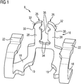
- Figure 1 shows a three dimensional perspective view of a holding component 8 for securing together an injector cup 2 and a fuel injector 4, to form a fuel injector assembly.
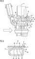
- FIG 3 shows a cross-section view of the holding element positioned in a flange 6 of the injector cup 2.
- Figure 2 shows a side view of a fuel injector cup 2 for receiving a fuel injector 4, the injector cup 2 comprising a generally cylindrical body having and axis L .
- the injector cup 2 is secured, typically by brazing or welding, to a generally tubular fuel rail (not shown) in a mechanically secure and hydraulically fluid tight manner.
- the cup 2 has an opening for receiving the fuel inlet 10 of the fuel injector 4.
- the fuel injector inlet 10 engages with the hydraulic connection to the fuel rail to provide a direct fuel path between the fuel rail and the fuel injector 4 through the injector cup 2.
- the fuel injector 4 is generally cylindrical and has an axis coaxial with the axis L.
- the fuel injector 4 has a circumferential groove 12 which is engageable by the holding component 8, described hereinafter, which is used to secure and locate the fuel injector positively in the injector cup 2.
- the injector cup 2 has a radially extending peripheral flange 6 at its lower end, a slot 14 being formed in the flange to receive and securely engage an engagement element 16 of the holding component 8.
- the holding component 8 has two generally parallel supporting arms 18 extending from the engagement element 16 which are adapted to engage opposite sides of a groove 12 on outer surface of the fuel injector 4.
- the support arms 18 extend substantially perpendicular to the engagement element 16.
- the engagement element 16 extends substantially parallel to the longitudinal axis L and the support arms 18 extend substantially perpendicularly to the longitudinal axis L.
- the two supporting arms 18 have arcuate, facing recesses 19 which serve to engage the groove 12 on the fuel injector 4.
- the groove 12 may be annular or two grooves, one to engage each of the supporting arms 18 may be provided on opposite sides of the fuel injector 4.
- the supporting arms 18 extend into resilient extensions 20 which have an arcuate section 21 which curves through substantially 180° to an end section having a wave form 22 which has a plurality of peaks 24 extending along the length of the waveform, two in the example shown.
- the plurality of peaks 24 engage the underside of the peripheral flange 6 at two spaced apart contact points 38.
- the fuel injector 4 is thus securely in contact with the injector cup 2 at four spaced points around the periphery of the injector cup 2.
- the supporting arm 18, arcuate section 21 and resilient extension 20 form a substantial U shape.
- the free end of the resilient extension is able to move in directions parallel to the longitudinal direction providing it with resilience and enabling the resilient extension together with the supporting arm 19 engaged with the grove 12 to provide an axial force between the fuel injector 4 and the injector cup 2 so as to secure the fuel injector 4 to the injector cup 2.
- the holding component 8 has an engagement element 16 comprising two spaced engagement arms 26 extending generally parallel to the axis L and substantially at right angles to the supporting arms 18.
- Each engagement arm 26 has a main shank 28 which culminates in an enlarged section at its free end having an inclined outer surface 32.
- the slope of the inclination of the two surfaces 32 are directed inwardly towards the other surface 32 to provide a reducing dimension in the lateral direction towards the outer ends of the two engagement arms 26.
- a shoulder 30 is formed between the enlarged section and the main shank 28.
- each inner facing edges 36 of each engagement arm 26 is formed with an undercut 34 to facilitate bending of the engagement arms 26 towards each other.
- the supporting arms 18 of the holding component 8 are the first inserted in the groove 12 in the fuel injector 4.
- the fuel injector is then offered up into the injector cup 2 with the engagement arms 26 aligned with the slot 14 in the peripheral flange of the injector cup 2.
- the inclined outer surfaces 32 of the arms engage the edges of the slot 14 and are resiliently deflected inwardly until the enlarged section passes through the slot and snaps outwardly to secure the holding component 8 to the injector cup 2.
- the resilient extension 20 together with the supporting arm 18 engaged with the groove 12 provides an axial force between the fuel injector 4 and the injector cup 2 and the engagement element 16 provides radial orientation of the fuel injector 4 with respect to the injector cup 2.
- Figure 4 illustrates the feature of the present disclosure that if an accidental lateral force is applied to the fuel injector 4 in the direction of the arrow A, the disturbing force is transmitted to the injector cup 2 at the four contact points 38 between the resilient extension 20 and the injector cup 2 and is distributed about the periphery of the injector cup 2. In this way, the fuel injector 4 is maintained in the correct alignment on the longitudinal axis L of the injector cup 2 and tilting of the fuel injector 4 about the longitudinal axis L is prevented.
- the holding component 8 may be formed by shaping or pressing from a resilient sheet metal material, which may be stainless steel.
- the holding component 8 may manufactured from a single flat sheet of metal by simply folding and shaping the material into the component and is particularly advantageous in providing a very lightweight, cost-effective and speedy solution.
- the holding component prefferably be formed of a plastics material, for example moulded plastics material.
- Figures 4 and 5 illustrate a comparison arrangement in which a holding component 8' in which similar parts are designated with the same reference number and a ' sign.
- the comparison holding component 8' has an engagement element 16' and two supporting arms 18', each of which extend via an arcuate section 21' into a resilient extension 20'.
- the resilient extension 20' has a single peak 24' so that the single peak 24' engages the injector cup 2 at a single position 38'.
- the one-piece holding element 8 described herein provides three orientation functions: a retaining function which provides an axial force in the longitudinal direction L for attaching the fuel injector 4 to the injector cup 2; an orientation function which prevents radial movement of both the holding element 8 about the longitudinal axis L and relative radial movement between the injector cup 2 and the fuel injector 4, and an anti-tilting function that is provided by the at least two contact points 38 between the extension 20 of the supporting arms of the holding element 8 and the injector cup 2, for example the lower surface of a flange 6 of the injector cup 2.
Landscapes
- Engineering & Computer Science (AREA)
- Chemical & Material Sciences (AREA)
- Combustion & Propulsion (AREA)
- Mechanical Engineering (AREA)
- General Engineering & Computer Science (AREA)
- Fuel-Injection Apparatus (AREA)
Abstract
Description
- The present disclosure relates to a fuel injection assembly for an internal combustion engine, particularly but not exclusively, for a gasoline direct injection internal combustion engine.
- Fuel injection assemblies are widely used for injecting fuel into an internal combustion engine, commonly having an injector for each cylinder of a multi-cylinder engine in which the fuel is supplied from a reservoir in the form of a common rail to which each of the injectors is connected. The assembly is also suitable for use in a single cylinder engine.
- The injectors may be secured directly to the cylinder head of the engine to project into the combustion chamber. Such arrangements have a disadvantage in that noise generated by the injection and combustion process is transmitted through the engine to the exterior. In order to reduce noise transmission, one solution is to isolate the injector from direct mechanical connection with the engine, for example by suspending the injector in a fuel rail injector cup with a flexible seal therebetween to prevent leakage of fuel from the injector cup past the fuel injector. This is achieved by means of a holding element, commonly called a fork clip. The injector cup itself is secured to the fuel rail and the engine. In this way there is no direct mechanical coupling between the injector and the engine components.
- A problem arises in that it possible for the fuel injector to be accidently displaced so that its axis is angularly displaced relative to the axis of the injector cup. This accidental displacement can occur, at different stages of the assembly onto the vehicle engine. Initially the fuel injector and cup are formed as a sub-assembly which may then be packaged, transported to the engine assembly plant and unpacked for assembly. At each stage, the components of the subassembly may be accidently displaced. It is necessary, however, for the angular position of the fuel injector to be precisely positioned relative to the injector cup so that the fuel injector fuel output is in the correct position for fuel injection into the combustion chamber. Furthermore, the angular displacement may lead to the seal between injector and the cup being broken leading, in operation, to leakage of fuel under high pressure which would a very dangerous situation. In the known arrangements this is achieved by means of a further component known as an indexing clip. Such arrangements are shown for example in
US Patent No.8,479,710 andWO 2015/135732 . - The present disclosure seeks to provide a fuel injection assembly with an improved arrangement for positioning the fuel injector.
- According to the present disclosure there is provided a fuel injection assembly is provided that comprises an elongate fuel injector having a fuel inlet port and a fuel outlet port, an injector cup, and a holding component for securing the fuel injector in the injector cup. The injector cup comprises a generally cylindrical body having a longitudinal axis L, an upper end adapted to be connected to a fuel rail mechanically and hydraulically, and a lower end, the injector cup being open at its lower end to receive a fuel inlet port of the fuel injector. A slot is formed in the peripheral wall of the injector cup for receiving an engagement element of the holding component. The holding component further comprises two generally parallel supporting arms adapted to engage opposite sides of the fuel injector. The two supporting arms each have a resilient extension to resiliently engage the lower end of the injector cup on respective opposite sides of the fuel injector, each of the resilient extensions engaging the injector cup at at least two spaced points.
- The present disclosure provides a fuel injection assembly which has less components as the holding element and the indexing clip are combined into one component. Each resilient extension of each of the support arms engages the lower end of the injector cup on respective opposite sides of the fuel injector and at a minimum of two spaced points. This arrangement avoids the holding element being able to tilt relative to the longitudinal axis L so that a variation in the alignment of injector with respect to the injector cup can be hindered, in particular relative tilting of the fuel injector with respect to the injector cup and the longitudinal axis L of the injector cup can be avoided.
- The holding element described herein provides a retaining function which provides an axial force in the longitudinal direction L for attaching the fuel injector to the injector cup, an orientation function which prevents radial movement of both the holding element about the longitudinal axis L and relative radial movement between the injector cup and the fuel injector and an anti-tilting function that is provided by the at least two contact points between the extension of the supporting arms of the holding element and the injector cup, for example the lower surface of a flange of the injector cup. A single one-piece holding component provides all three functions, which reduces costs and eases assembly, for example compared to a multi-component arrangement.
- The supporting arm and its resilient extension may form a general U-shape in plan view with the engagement element extending from one end of the supporting arm substantially perpendicularly to the supporting arm and, when installed, parallel to the longitudinal axis. The resilient extension has a free end facing towards the engagement element which gives the resilient element its resilience as the resilient extension is able to move towards the supporting arm in response to force acting perpendicularly to the surface of the resilient extension.
- In the installed position, the supporting arms may extend substantially perpendicularly to the longitudinal axis L. The resilient extensions may extend substantially parallel to the supporting arms and also substantially perpendicular to the longitudinal axis in the installed position.
- In some embodiments, the two generally parallel supporting arms adapted to engage opposite sides of a groove in the outer surface of the fuel injector. The grove may be annular. In other embodiments, two or more grooves may be provided on opposite sides of the outer surface of the fuel injector with one supporting arm of the holding component engaging with one of the grooves on opposite sides of the fuel injector.
- In some embodiments, the resilient extensions are each profiled to have a waveform having a plurality of spaced peaks, at least two of the peaks engaging the injector cup at at least two spaced points. In embodiments including two peaks, both peaks engage the injector cup at two points that are spaced apart on the injector cup.
- In some embodiments, the injector cup has a peripheral flange at its lower end, and each of the peaks engages with the peripheral flange. In some embodiments, the slot for the engagement element is formed in the flange.
- In some embodiments, the engagement element comprises a pair of spaced engagement arms extending generally parallel to the axis L and substantially at right angles from the supporting arms. Each of the engagement arms has a shank having at its free end an enlarged section having an inclined outer surface. In the installed condition, the enlarged section projects through the slot, and provides a shoulder to engage the flange of the injector cup.
- In some embodiments, each of the spaced engagement arms have adjacent the junction with the supporting arms an undercut on their facing edges.
- In some embodiments, the holding component is a one-piece component formed from a sheet metal material such as stainless steel or a plastics material.
- The disclosure also provides a holding component for a fuel injection assembly for securing a fuel injector in fuel injector cup, the injector cup comprising a generally cylindrical body extending along a longitudinal axis L, an upper end adapted to be connected to a fuel rail mechanically and hydraulically, and a lower end open to receive a fuel inlet port of the fuel injector. A slot is being formed in the peripheral wall of the injector cup for receiving an engagement element of the holding component. The holding component comprises the engagement element and further comprises two generally parallel supporting arms adapted to engage opposite sides of the fuel injector. The two supporting arms each have a resilient extension which, in the installed position, are adapted to resiliently engage the lower end of the injector cup on respective opposite sides of the fuel injector, each of the resilient extensions being adapted to engage the injector cup at at least two spaced points.
- In some embodiments, the resilient extensions are each profiled to have a waveform having a plurality of spaced peaks, at least two of the peaks engaging the injector cup at at least two spaced points.
- The supporting arm and its resilient extension may form a general U-shape in plan view with the engagement element extending from one end of the supporting arm substantially perpendicularly to the supporting arm and, when installed, parallel to the longitudinal axis. The resilient extension has a free end facing towards the engagement element which gives the resilient element its resilience as the resilient extension is able to move towards the supporting arm in response to force acting perpendicularly to the surface of the resilient extension.
- In the installed position, the supporting arms may extend substantially perpendicularly to the longitudinal axis L. The resilient extensions may extend substantially parallel to the supporting arms and also substantially perpendicular to the longitudinal axis in the installed position.
- In some embodiments, the engagement element comprises a pair of spaced engagement arms extending generally at right angles from the supporting arms, each of the engagement arms having a shank having at its free end an enlarged section having an inclined outer surface, the enlarged section, in the installed condition, being adapted to project through the slot, and further providing a shoulder adapted to abut the flange of the injector cup.
- In some embodiments, each of the spaced engagement arms have adjacent the junction with the supporting arms an undercut on their facing edges.
- In some embodiments, the holding component is a one-piece component formed from a sheet metal material, or a one-piece component formed of a plastics material.
- Embodiments in accordance with this disclosure have the advantage of a low-cost solution to the known problem of accidental displacement of the fuel injector in the injector cup during manufacture and assembly both because of the reduction in the number of individual components, the lower cost of production of the component and the speeding up of assembly. Assembly of the fuel injector and injector cup into a sub-assembly is a simple two stage operation; the holding component is pushed into place on the injector, the injector is inserted in the injector cup to locate the injector in the injector cup until the engagement element snaps into engagement with the injector cup to complete the sub-assembly.
- A preferred embodiment of the present invention will now be described by way of example with reference to the accompanying drawings, in which:-
-
Figure 1 shows a holding component according to the invention for securing a fuel injector assembly of an injector cup and a fuel injector, -
Figure 2 shows an assembly of a fuel injector and an injector cup, -
Figure 3 shows a schematic view of the holding component positioned in the injector cup, -
Figure 4 shows an assembly of a fuel injector and an injector cup using a comparison holding component, and -
Figure 5 shows a schematic view of the comparison holding component positioned in the injector cup, - In this description reference is made to upper and lower ends but this nomenclature is used solely for descriptive convenience. In the installed condition, the orientation of the assembly depends upon the particular configuration.
-
Figure 1 shows a three dimensional perspective view of aholding component 8 for securing together aninjector cup 2 and afuel injector 4, to form a fuel injector assembly. For clarity, it will be described in connection with the assembly illustrated in Figures and 3, wherebyfigure 3 shows a cross-section view of the holding element positioned in aflange 6 of theinjector cup 2. -
Figure 2 shows a side view of afuel injector cup 2 for receiving afuel injector 4, theinjector cup 2 comprising a generally cylindrical body having and axis L . At its upper end (not shown) theinjector cup 2 is secured, typically by brazing or welding, to a generally tubular fuel rail (not shown) in a mechanically secure and hydraulically fluid tight manner. At its lower end thecup 2 has an opening for receiving the fuel inlet 10 of thefuel injector 4. The fuel injector inlet 10 engages with the hydraulic connection to the fuel rail to provide a direct fuel path between the fuel rail and thefuel injector 4 through theinjector cup 2. Thefuel injector 4 is generally cylindrical and has an axis coaxial with the axis L. Thefuel injector 4 has acircumferential groove 12 which is engageable by the holdingcomponent 8, described hereinafter, which is used to secure and locate the fuel injector positively in theinjector cup 2. - The
injector cup 2 has a radially extendingperipheral flange 6 at its lower end, aslot 14 being formed in the flange to receive and securely engage anengagement element 16 of the holdingcomponent 8. The holdingcomponent 8 has two generally parallel supportingarms 18 extending from theengagement element 16 which are adapted to engage opposite sides of agroove 12 on outer surface of thefuel injector 4. Thesupport arms 18 extend substantially perpendicular to theengagement element 16. In the installed positioned, theengagement element 16 extends substantially parallel to the longitudinal axis L and thesupport arms 18 extend substantially perpendicularly to the longitudinal axis L. Intermediate their length, the two supportingarms 18 have arcuate, facingrecesses 19 which serve to engage thegroove 12 on thefuel injector 4. Thegroove 12 may be annular or two grooves, one to engage each of the supportingarms 18 may be provided on opposite sides of thefuel injector 4. - The supporting
arms 18 extend intoresilient extensions 20 which have anarcuate section 21 which curves through substantially 180° to an end section having awave form 22 which has a plurality ofpeaks 24 extending along the length of the waveform, two in the example shown. The plurality ofpeaks 24 engage the underside of theperipheral flange 6 at two spaced apart contact points 38. Thefuel injector 4 is thus securely in contact with theinjector cup 2 at four spaced points around the periphery of theinjector cup 2. The supportingarm 18,arcuate section 21 andresilient extension 20 form a substantial U shape. The free end of the resilient extension is able to move in directions parallel to the longitudinal direction providing it with resilience and enabling the resilient extension together with the supportingarm 19 engaged with thegrove 12 to provide an axial force between thefuel injector 4 and theinjector cup 2 so as to secure thefuel injector 4 to theinjector cup 2. - As shown particularly in
Figure 1 , the holdingcomponent 8 has anengagement element 16 comprising two spacedengagement arms 26 extending generally parallel to the axis L and substantially at right angles to the supportingarms 18. Eachengagement arm 26 has amain shank 28 which culminates in an enlarged section at its free end having an inclinedouter surface 32. The slope of the inclination of the twosurfaces 32 are directed inwardly towards theother surface 32 to provide a reducing dimension in the lateral direction towards the outer ends of the twoengagement arms 26. On the outer edges of the engagement arms ashoulder 30 is formed between the enlarged section and themain shank 28. - Adjacent the junction of each
engagement arm 26 with the supportingarms 18, each inner facing edges 36 of eachengagement arm 26 is formed with an undercut 34 to facilitate bending of theengagement arms 26 towards each other. - To assemble the
fuel injector 4 to theinjector cup 2, the supportingarms 18 of the holdingcomponent 8 are the first inserted in thegroove 12 in thefuel injector 4. The fuel injector is then offered up into theinjector cup 2 with theengagement arms 26 aligned with theslot 14 in the peripheral flange of theinjector cup 2. The inclinedouter surfaces 32 of the arms engage the edges of theslot 14 and are resiliently deflected inwardly until the enlarged section passes through the slot and snaps outwardly to secure theholding component 8 to theinjector cup 2. Theresilient extension 20 together with the supportingarm 18 engaged with thegroove 12 provides an axial force between thefuel injector 4 and theinjector cup 2 and theengagement element 16 provides radial orientation of thefuel injector 4 with respect to theinjector cup 2. -
Figure 4 illustrates the feature of the present disclosure that if an accidental lateral force is applied to thefuel injector 4 in the direction of the arrow A, the disturbing force is transmitted to theinjector cup 2 at the fourcontact points 38 between theresilient extension 20 and theinjector cup 2 and is distributed about the periphery of theinjector cup 2. In this way, thefuel injector 4 is maintained in the correct alignment on the longitudinal axis L of theinjector cup 2 and tilting of thefuel injector 4 about the longitudinal axis L is prevented. - The holding
component 8 may be formed by shaping or pressing from a resilient sheet metal material, which may be stainless steel. The holdingcomponent 8 may manufactured from a single flat sheet of metal by simply folding and shaping the material into the component and is particularly advantageous in providing a very lightweight, cost-effective and speedy solution. - In an alternative embodiment, it is possible for the holding component to be formed of a plastics material, for example moulded plastics material.
-
Figures 4 and 5 illustrate a comparison arrangement in which a holding component 8' in which similar parts are designated with the same reference number and a ' sign. The comparison holding component 8' has an engagement element 16' and two supporting arms 18', each of which extend via an arcuate section 21' into a resilient extension 20'. In the comparison holding component 8', the resilient extension 20' has a single peak 24' so that the single peak 24' engages theinjector cup 2 at a single position 38'. - In this arrangement, an accidental lateral force is applied in the direction of the arrow A can have the result that the
fuel injector 4 pivots or rolls about the contact point 38' so that the axis of thefuel injector 4 is pivoted to lie on the line L". The securing enlarged part of the engagement element 16' is lifted clear of the peripheral flange g of theinjector cup 2 which renders the position of thefuel injector 4 unstable. If thefuel injector 4 were inserted into the engine in this position, incorrect combustion with reduced performance and increased emissions results. The possibility that this could happen means that the injector cup/fuel injector subassembly must be inspected immediately before the fuel injection system is fitted to the engine, which results in increased costs and an increase in the assembly time for the engine. - To summarise, the one-
piece holding element 8 described herein provides three orientation functions: a retaining function which provides an axial force in the longitudinal direction L for attaching thefuel injector 4 to theinjector cup 2; an orientation function which prevents radial movement of both the holdingelement 8 about the longitudinal axis L and relative radial movement between theinjector cup 2 and thefuel injector 4, and an anti-tilting function that is provided by the at least twocontact points 38 between theextension 20 of the supporting arms of the holdingelement 8 and theinjector cup 2, for example the lower surface of aflange 6 of theinjector cup 2. -
- 2
- Fuel injector cup
- 4
- Fuel injector
- 6
- Peripheral flange
- 8
- Holding component
- 8'
- Comparison holding component
- 10
- Fuel inlet port
- 12
- Groove
- 14
- Slot
- 16
- Engagement element
- 18
- Supporting arms
- 19
- Recess
- 20
- Resilient extensions
- 21
- Arcuate section
- 22
- Wave form
- 24
- Peak
- 26
- Engagement arm
- 28
- Shank
- 30
- Shoulder
- 32
- Inclined surface
- 34
- Undercut
- 36
- Facing edge
- 38
- Contact points
Claims (14)
- A fuel injection assembly comprising an elongate fuel injector (4) having a fuel inlet port and a fuel outlet port, an injector cup (2), and a holding component (8) for securing the fuel injector (4) in the injector cup (2),
wherein the injector cup (2) comprises a generally cylindrical body having a longitudinal axis L, an upper end adapted to be connected to a fuel rail mechanically and hydraulically, and a lower end, the injector cup (2) being open at its lower end to receive a fuel inlet port (10) of the fuel injector (4), wherein a slot (14) is formed in the peripheral wall of the injector cup (2) for receiving an engagement element (16) of the holding component (8),
wherein the holding component (8) further comprises two generally parallel supporting arms (18) adapted to engage opposite sides of the fuel injector (4),
wherein the two supporting arms (18) each have a resilient extension (20) to resiliently engage the lower end of the injector cup (2) on respective opposite sides of the fuel injector (4), each of the resilient extensions (20) engaging the injector cup (2) at at least two spaced points. - A fuel injection assembly according to claim 1, wherein the resilient extensions (20) are each profiled to have a waveform (22) having a plurality of spaced peaks (24), at least two of peaks (24) engaging the injector cup (2) at at least two spaced points.
- A fuel injection assembly according to claim 2, wherein the injector cup (2) has a peripheral flange (6) at its lower end, and each of the peaks (24) engages with the peripheral flange (6)
- A fuel injection assembly according to any one of claims 1 to 3, wherein the injector cup (2) has a peripheral flange (6) and the slot (14) for the engagement element (16) is formed in the flange (6).
- A fuel injection assembly according to any one claims 1 to 4, wherein the engagement element (16) comprises a pair of spaced engagement arms (26) extending generally parallel to the longitudinal axis L and substantially at right angles from the supporting arms (18), each of the engagement arms having a shank (28) having at its free end an enlarged section having an inclined outer surface (32), the enlarged section, in the installed condition, projecting through the slot (14), and providing a shoulder (30) adapted to project through the slot (14) to engage the flange (6) of the injector cup (2).
- A fuel injection assembly according to claim 5, wherein each of the spaced engagement arms (26) have adjacent the junction with the supporting arms (18) an undercut (34) on their facing edges (36)
- A fuel injection assembly according to any one of the preceding claims, wherein the holding component (8) is a one-piece component formed from a sheet metal material.
- A fuel injection assembly according to any one of claims 1 to 6, wherein the holding component (8) is a one-piece component formed of a plastics material.
- A holding component for a fuel injection assembly for securing a fuel injector (4) in fuel injector cup (2), the injector cup (2) comprising a generally cylindrical body extending along a longitudinal axis L, an upper end adapted to be connected to a fuel rail mechanically and hydraulically, and a lower end open to receive a fuel inlet port (10) of the fuel injector (4), a slot (14) being formed in the peripheral wall of the injector cup (2) for receiving an engagement element (16) of the holding component (8),
wherein the holding component (8) further comprises two generally parallel supporting arms (18) adapted to engage opposite sides of the fuel injector (4), wherein the two supporting arms (18) each have a resilient extension (20) which, in the installed position, are adapted to resiliently engage the lower end of the injector cup (2) on respective opposite sides of the fuel injector (4), each of the resilient extensions being adapted to engage the injector cup (2) at at least two spaced points. - A holding component according to claim 9, wherein the resilient extensions (20) are each profiled to have a waveform (22) having a plurality of spaced peaks (24), at least two of the peaks (24) engaging the injector cup (2) at at least two spaced points.
- A holding component according to claim 10, wherein the engagement element (16) comprises a pair of spaced engagement arms (26) extending generally at right angles from the supporting arms (18), each of the engagement arms having a shank (28) having at its free end an enlarged section having an inclined outer surface (32), the enlarged section, in the installed condition, being adapted to project through the slot (14), and further providing a shoulder (30) adapted to abut the flange (6) of the injector cup (2).
- A holding component according to claim 11 wherein each of the spaced engagement arms (26) have adjacent the junction with the supporting arms (18) an undercut (34) on their facing edges (36).
- A holding component according to any one of the claims 9-12 wherein the holding component (8) is a one-piece component formed from a sheet metal material.
- A holding component according to any one of claims 9 to 12, wherein the holding component (8) is a one-piece component formed of a plastics material.
Priority Applications (1)
| Application Number | Priority Date | Filing Date | Title |
|---|---|---|---|
| EP19193699.6A EP3786440A1 (en) | 2019-08-27 | 2019-08-27 | A fuel injection assembly for an internal combustion engine and holding component |
Applications Claiming Priority (1)
| Application Number | Priority Date | Filing Date | Title |
|---|---|---|---|
| EP19193699.6A EP3786440A1 (en) | 2019-08-27 | 2019-08-27 | A fuel injection assembly for an internal combustion engine and holding component |
Publications (1)
| Publication Number | Publication Date |
|---|---|
| EP3786440A1 true EP3786440A1 (en) | 2021-03-03 |
Family
ID=67770399
Family Applications (1)
| Application Number | Title | Priority Date | Filing Date |
|---|---|---|---|
| EP19193699.6A Withdrawn EP3786440A1 (en) | 2019-08-27 | 2019-08-27 | A fuel injection assembly for an internal combustion engine and holding component |
Country Status (1)
| Country | Link |
|---|---|
| EP (1) | EP3786440A1 (en) |
Citations (5)
| Publication number | Priority date | Publication date | Assignee | Title |
|---|---|---|---|---|
| JP2010168964A (en) * | 2009-01-21 | 2010-08-05 | Denso Corp | Fuel injection device |
| US20130074951A1 (en) * | 2010-05-18 | 2013-03-28 | Continental Automotive Gmbh | Fuel Cup |
| US8479710B2 (en) | 2010-05-07 | 2013-07-09 | Continental Automotive Systems Us, Inc. | Injector to fuel rail coupling structure for high pressure direct injection engines |
| US20150101572A1 (en) * | 2013-10-10 | 2015-04-16 | Continental Automotive Gmbh | Fluid Injection Assembly For A Combustion Engine |
| WO2015135732A1 (en) | 2014-03-14 | 2015-09-17 | Continental Automotive Gmbh | Fuel injection assembly |
-
2019
- 2019-08-27 EP EP19193699.6A patent/EP3786440A1/en not_active Withdrawn
Patent Citations (5)
| Publication number | Priority date | Publication date | Assignee | Title |
|---|---|---|---|---|
| JP2010168964A (en) * | 2009-01-21 | 2010-08-05 | Denso Corp | Fuel injection device |
| US8479710B2 (en) | 2010-05-07 | 2013-07-09 | Continental Automotive Systems Us, Inc. | Injector to fuel rail coupling structure for high pressure direct injection engines |
| US20130074951A1 (en) * | 2010-05-18 | 2013-03-28 | Continental Automotive Gmbh | Fuel Cup |
| US20150101572A1 (en) * | 2013-10-10 | 2015-04-16 | Continental Automotive Gmbh | Fluid Injection Assembly For A Combustion Engine |
| WO2015135732A1 (en) | 2014-03-14 | 2015-09-17 | Continental Automotive Gmbh | Fuel injection assembly |
Similar Documents
| Publication | Publication Date | Title |
|---|---|---|
| KR0185733B1 (en) | Fuel injection device for internal combustion engines | |
| EP3494301B1 (en) | Holding component and fuel injection assembly for an internal combustion engine | |
| US11204008B2 (en) | Fuel injection assembly for an internal combustion engine | |
| EP2860388B1 (en) | Fluid injection assembly for a combustion engine | |
| US10436163B2 (en) | Fuel rail assembly for an internal combustion engine | |
| JPH02240495A (en) | Coupling element | |
| KR102048118B1 (en) | A fuel injection assembly for an internal combustion engine | |
| CN105593512A (en) | Mounting Structure of Nozzle Plate for Fuel Injection Device | |
| EP3309385B1 (en) | Injector cup, spring clip, fluid injection assembly and method for its assembling | |
| CN109328266A (en) | fuel injector assembly | |
| KR101963955B1 (en) | Fuel delivery assembly for an internal combustion engine | |
| KR20010086261A (en) | Fuel injection device | |
| EP3786441A1 (en) | Fuel injection assembly for an internal combustion engine | |
| EP1793122B1 (en) | Fuel injector assembly | |
| EP3508716A1 (en) | Combination of a clip and an aligning element and fluid injection assembly | |
| EP3636915A1 (en) | Fuel injection assembly for an internal combustion engine | |
| EP3168453B1 (en) | Interface assembly for a fuel injector |
Legal Events
| Date | Code | Title | Description |
|---|---|---|---|
| PUAI | Public reference made under article 153(3) epc to a published international application that has entered the european phase |
Free format text: ORIGINAL CODE: 0009012 |
|
| STAA | Information on the status of an ep patent application or granted ep patent |
Free format text: STATUS: THE APPLICATION HAS BEEN PUBLISHED |
|
| AK | Designated contracting states |
Kind code of ref document: A1 Designated state(s): AL AT BE BG CH CY CZ DE DK EE ES FI FR GB GR HR HU IE IS IT LI LT LU LV MC MK MT NL NO PL PT RO RS SE SI SK SM TR |
|
| STAA | Information on the status of an ep patent application or granted ep patent |
Free format text: STATUS: REQUEST FOR EXAMINATION WAS MADE |
|
| 17P | Request for examination filed |
Effective date: 20210903 |
|
| RBV | Designated contracting states (corrected) |
Designated state(s): AL AT BE BG CH CY CZ DE DK EE ES FI FR GB GR HR HU IE IS IT LI LT LU LV MC MK MT NL NO PL PT RO RS SE SI SK SM TR |
|
| RAP3 | Party data changed (applicant data changed or rights of an application transferred) |
Owner name: VITESCO TECHNOLOGIES GMBH |
|
| STAA | Information on the status of an ep patent application or granted ep patent |
Free format text: STATUS: EXAMINATION IS IN PROGRESS |
|
| 17Q | First examination report despatched |
Effective date: 20211217 |
|
| P01 | Opt-out of the competence of the unified patent court (upc) registered |
Effective date: 20230530 |
|
| GRAP | Despatch of communication of intention to grant a patent |
Free format text: ORIGINAL CODE: EPIDOSNIGR1 |
|
| STAA | Information on the status of an ep patent application or granted ep patent |
Free format text: STATUS: GRANT OF PATENT IS INTENDED |
|
| INTG | Intention to grant announced |
Effective date: 20231012 |
|
| STAA | Information on the status of an ep patent application or granted ep patent |
Free format text: STATUS: THE APPLICATION IS DEEMED TO BE WITHDRAWN |
|
| 18D | Application deemed to be withdrawn |
Effective date: 20240223 |