EP3786420A1 - Dual bypass filter cascade - Google Patents
Dual bypass filter cascade Download PDFInfo
- Publication number
- EP3786420A1 EP3786420A1 EP20191221.9A EP20191221A EP3786420A1 EP 3786420 A1 EP3786420 A1 EP 3786420A1 EP 20191221 A EP20191221 A EP 20191221A EP 3786420 A1 EP3786420 A1 EP 3786420A1
- Authority
- EP
- European Patent Office
- Prior art keywords
- filter
- coarse
- fine
- flow
- mesh filter
- Prior art date
- Legal status (The legal status is an assumption and is not a legal conclusion. Google has not performed a legal analysis and makes no representation as to the accuracy of the status listed.)
- Granted
Links
Images


Classifications
-
- B—PERFORMING OPERATIONS; TRANSPORTING
- B01—PHYSICAL OR CHEMICAL PROCESSES OR APPARATUS IN GENERAL
- B01D—SEPARATION
- B01D35/00—Filtering devices having features not specifically covered by groups B01D24/00 - B01D33/00, or for applications not specifically covered by groups B01D24/00 - B01D33/00; Auxiliary devices for filtration; Filter housing constructions
- B01D35/14—Safety devices specially adapted for filtration; Devices for indicating clogging
- B01D35/147—Bypass or safety valves
-
- B—PERFORMING OPERATIONS; TRANSPORTING
- B01—PHYSICAL OR CHEMICAL PROCESSES OR APPARATUS IN GENERAL
- B01D—SEPARATION
- B01D29/00—Filters with filtering elements stationary during filtration, e.g. pressure or suction filters, not covered by groups B01D24/00 - B01D27/00; Filtering elements therefor
- B01D29/11—Filters with filtering elements stationary during filtration, e.g. pressure or suction filters, not covered by groups B01D24/00 - B01D27/00; Filtering elements therefor with bag, cage, hose, tube, sleeve or like filtering elements
- B01D29/31—Self-supporting filtering elements
- B01D29/33—Self-supporting filtering elements arranged for inward flow filtration
-
- B—PERFORMING OPERATIONS; TRANSPORTING
- B01—PHYSICAL OR CHEMICAL PROCESSES OR APPARATUS IN GENERAL
- B01D—SEPARATION
- B01D29/00—Filters with filtering elements stationary during filtration, e.g. pressure or suction filters, not covered by groups B01D24/00 - B01D27/00; Filtering elements therefor
- B01D29/50—Filters with filtering elements stationary during filtration, e.g. pressure or suction filters, not covered by groups B01D24/00 - B01D27/00; Filtering elements therefor with multiple filtering elements, characterised by their mutual disposition
- B01D29/56—Filters with filtering elements stationary during filtration, e.g. pressure or suction filters, not covered by groups B01D24/00 - B01D27/00; Filtering elements therefor with multiple filtering elements, characterised by their mutual disposition in series connection
- B01D29/58—Filters with filtering elements stationary during filtration, e.g. pressure or suction filters, not covered by groups B01D24/00 - B01D27/00; Filtering elements therefor with multiple filtering elements, characterised by their mutual disposition in series connection arranged concentrically or coaxially
-
- B—PERFORMING OPERATIONS; TRANSPORTING
- B01—PHYSICAL OR CHEMICAL PROCESSES OR APPARATUS IN GENERAL
- B01D—SEPARATION
- B01D35/00—Filtering devices having features not specifically covered by groups B01D24/00 - B01D33/00, or for applications not specifically covered by groups B01D24/00 - B01D33/00; Auxiliary devices for filtration; Filter housing constructions
- B01D35/02—Filters adapted for location in special places, e.g. pipe-lines, pumps, stop-cocks
-
- F—MECHANICAL ENGINEERING; LIGHTING; HEATING; WEAPONS; BLASTING
- F01—MACHINES OR ENGINES IN GENERAL; ENGINE PLANTS IN GENERAL; STEAM ENGINES
- F01D—NON-POSITIVE DISPLACEMENT MACHINES OR ENGINES, e.g. STEAM TURBINES
- F01D25/00—Component parts, details, or accessories, not provided for in, or of interest apart from, other groups
- F01D25/18—Lubricating arrangements
-
- F—MECHANICAL ENGINEERING; LIGHTING; HEATING; WEAPONS; BLASTING
- F05—INDEXING SCHEMES RELATING TO ENGINES OR PUMPS IN VARIOUS SUBCLASSES OF CLASSES F01-F04
- F05D—INDEXING SCHEME FOR ASPECTS RELATING TO NON-POSITIVE-DISPLACEMENT MACHINES OR ENGINES, GAS-TURBINES OR JET-PROPULSION PLANTS
- F05D2260/00—Function
- F05D2260/60—Fluid transfer
- F05D2260/607—Preventing clogging or obstruction of flow paths by dirt, dust, or foreign particles
-
- F—MECHANICAL ENGINEERING; LIGHTING; HEATING; WEAPONS; BLASTING
- F05—INDEXING SCHEMES RELATING TO ENGINES OR PUMPS IN VARIOUS SUBCLASSES OF CLASSES F01-F04
- F05D—INDEXING SCHEME FOR ASPECTS RELATING TO NON-POSITIVE-DISPLACEMENT MACHINES OR ENGINES, GAS-TURBINES OR JET-PROPULSION PLANTS
- F05D2260/00—Function
- F05D2260/84—Redundancy
-
- F—MECHANICAL ENGINEERING; LIGHTING; HEATING; WEAPONS; BLASTING
- F05—INDEXING SCHEMES RELATING TO ENGINES OR PUMPS IN VARIOUS SUBCLASSES OF CLASSES F01-F04
- F05D—INDEXING SCHEME FOR ASPECTS RELATING TO NON-POSITIVE-DISPLACEMENT MACHINES OR ENGINES, GAS-TURBINES OR JET-PROPULSION PLANTS
- F05D2300/00—Materials; Properties thereof
- F05D2300/60—Properties or characteristics given to material by treatment or manufacturing
- F05D2300/601—Fabrics
- F05D2300/6012—Woven fabrics
Definitions
- the present disclosure relates generally to gas turbine engines and, more particularly, to oil or lubricant filtration systems used in gas turbine engines.
- Gas turbine engines typically include a fan section, a compressor section, a combustor section and a turbine section.
- the fan section drives air along a bypass flow path while the compressor section drives air along a core flow path.
- air is pressurized in the compressor section and is mixed with fuel and burned in the combustor section to generate hot combustion gases.
- the hot combustion gases flow through the turbine section, which extracts energy from the hot combustion gases to power the compressor section and other gas turbine engine loads, such as those required to rotate a fan in the fan section.
- the compressor section typically includes low pressure and high pressure compressors
- the turbine section includes low pressure and high pressure turbines.
- the rotating components of a gas turbine engine such as, for example, the low pressure and high pressure compressors, the low pressure and high pressure turbines and the fan, rely on various bearing systems or gear systems located throughout the engine.
- the bearing systems or gear systems typically exhibit close tolerances among the working parts or contact surfaces in order to facilitate high rotational velocities of the rotating components.
- a supply of oil or lubricant that is generally debris-free is delivered to the working parts or contact surfaces of the various components comprising the bearing or gear systems.
- filtration systems are typically incorporated into one or more lubrication systems configured to deliver the oil or lubricant to the gear or bearing systems.
- the filtration system includes a fine mesh filter configured for disposition within a chamber and defining a first volume, the first volume in fluid communication with a main exit conduit; and a coarse mesh filter configured for disposition within the chamber and at least partially surrounding the fine mesh filter, the coarse mesh filter and the fine mesh filter defining a second volume, the second volume in fluid communication with a first bypass valve, the coarse mesh filter and the chamber defining a third volume, the third volume in fluid communication with a second bypass valve.
- the fine mesh filter defines a characteristic fine mesh size and the coarse mesh filter defines a characteristic coarse mesh size greater than the characteristic fine mesh size.
- the characteristic coarse mesh size is about thirty micrometers to about forty micrometers.
- the characteristic fine mesh size is about three micrometers to about six micrometers.
- the first bypass valve is configured to fluidly couple a fine filter bypass conduit to the second volume.
- the second bypass valve is configured to fluidly couple a coarse filter bypass conduit to the third volume.
- the fine filter bypass conduit is fluidly coupled to the main exit conduit and to an outlet conduit.
- the coarse filter bypass conduit is fluidly coupled to the main exit conduit and to the outlet conduit.
- the first bypass valve includes a first bias mechanism responsive to a fine filter bypass threshold pressure.
- the second bypass valve includes a second bias mechanism responsive to a coarse filter bypass threshold pressure.
- the coarse filter bypass threshold pressure is greater than the fine filter bypass threshold pressure.
- a filtration system for a gas turbine engine includes a chamber; a fine mesh filter configured for disposition within the chamber and defining a first volume, the first volume in fluid communication with a main exit conduit; and a coarse mesh filter configured for disposition within the chamber and at least partially surrounding the fine mesh filter, the coarse mesh filter and the fine mesh filter defining a second volume, the second volume in fluid communication with a first bypass valve, the coarse mesh filter and the chamber defining a third volume, the third volume in fluid communication with a second bypass valve.
- the main exit conduit is fluidly coupled to an outlet conduit, the outlet conduit configured to provide a lubricant to a component within the gas turbine engine.
- the component is a bearing system or a gear system.
- the first bypass valve is configured to fluidly couple a fine filter bypass conduit to the second volume and the second bypass valve is configured to fluidly couple a coarse filter bypass conduit to the third volume.
- the fine filter bypass conduit is fluidly coupled to the main exit conduit and to the outlet conduit and the coarse filter bypass conduit is fluidly coupled to the main exit conduit and to the outlet conduit.
- the first bypass valve includes a first bias mechanism responsive to a fine filter bypass threshold pressure
- the second bypass valve includes a second bias mechanism responsive to a coarse filter bypass threshold pressure and the coarse filter bypass threshold pressure is greater than the fine filter bypass threshold pressure.
- a method of filtering a flow of lubricant includes delivering the flow of lubricant to a chamber containing a fine mesh filter and a coarse mesh filter surrounding the fine mesh filter, the fine mesh filter defining a first volume in fluid communication with a main exit conduit; passing the flow of lubricant through the coarse mesh filter via a coarse mesh flow; passing the flow of lubricant through the fine mesh filter via a fine mesh flow; bypassing the flow of lubricant from passing through the fine mesh filter upon a fine filter pressure within a second volume defined by the coarse mesh filter and the fine mesh filter reaching a fine filter bypass threshold pressure; and bypassing the flow of lubricant from passing through the coarse mesh filter upon a coarse filter pressure within a third volume defined by the chamber and the coarse mesh filter reaching a coarse filter bypass threshold pressure.
- bypassing the flow of lubricant from passing through the fine mesh filter includes opening a first bypass valve and directing the flow of lubricant through a fine filter bypass conduit and into an outlet conduit. In various embodiments, bypassing the flow of lubricant from passing through the coarse mesh filter includes opening a second bypass valve and directing the flow of lubricant through a coarse filter bypass conduit and into the outlet conduit.
- references to "a,” “an” or “the” may include one or more than one and that reference to an item in the singular may also include the item in the plural. Further, all ranges may include upper and lower values and all ranges and ratio limits disclosed herein may be combined. Further, the term “about” is intended to include a degree of error associated with measurement of a particular quantity based upon equipment or techniques otherwise available at the time of filing the application. For example, “about” may include a range of ⁇ 8% or 5% or 2% of a given value.
- FIG. 1 schematically illustrates a gas turbine engine 20.
- the gas turbine engine 20 is disclosed herein as a two-spool turbofan that generally incorporates a fan section 22, a compressor section 24, a combustor section 26 and a turbine section 28.
- the fan section 22 drives air along a bypass flow path B in a bypass duct defined within a nacelle 15, while the compressor section 24 drives air along a core flow path C for compression and communication into the combustor section 26 and then expansion through the turbine section 28.
- the concepts described herein are not limited to use with two-spool turbofans as the teachings may be applied to other types of turbine engines.
- the gas turbine engine 20 generally includes a low speed spool 30 and a high speed spool 32 mounted for rotation about an engine central longitudinal axis A relative to an engine static structure 36 via several bearing systems 38.
- the low speed spool 30 generally includes an inner shaft 40 that interconnects a fan 42, a low pressure compressor 44 and a low pressure turbine 46.
- the inner shaft 40 is connected to the fan 42 through a speed change mechanism, which in this gas turbine engine 20 is illustrated as a fan drive gear system 48 configured to drive the fan 42 at a lower speed than that of the low speed spool 30.
- the high speed spool 32 includes an outer shaft 50 that interconnects a high pressure compressor 52 and a high pressure turbine 54.
- a combustor 56 is arranged in the gas turbine engine 20 between the high pressure compressor 52 and the high pressure turbine 54.
- a mid-turbine frame 57 of the engine static structure 36 is arranged generally between the high pressure turbine 54 and the low pressure turbine 46 and may include airfoils 59 in the core flow path C for guiding the flow into the low pressure turbine 46.
- the mid-turbine frame 57 further supports the several bearing systems 38 in the turbine section 28.
- the inner shaft 40 and the outer shaft 50 are concentric and rotate via the several bearing systems 38 about the engine central longitudinal axis A, which is collinear with longitudinal axes of the inner shaft 40 and the outer shaft 50.
- the air in the core flow path C is compressed by the low pressure compressor 44 and then the high pressure compressor 52, mixed and burned with fuel in the combustor 56, and then expanded over the high pressure turbine 54 and the low pressure turbine 46.
- the low pressure turbine 46 and the high pressure turbine 54 rotationally drive the respective low speed spool 30 and the high speed spool 32 in response to the expansion.
- each of the positions of the fan section 22, the compressor section 24, the combustor section 26, the turbine section 28, and the fan drive gear system 48 may be varied.
- the fan drive gear system 48 may be located aft of the combustor section 26 or even aft of the turbine section 28, and the fan section 22 may be positioned forward or aft of the location of the fan drive gear system 48.
- a filtration system 200 is illustrated with respect to various modes of operation.
- the filtration system 200 is part of a lubrication system that routes oil or lubricant from a source to one or more bearing or gear assemblies used within a gas turbine engine, such as, for example, one or more of the several bearing systems 38 or the fan drive gear system 48 used within the gas turbine engine 20 described above with reference to FIG. 1 .
- the filtration system 200 may be used to filter a flow of lubricant being routed to numerous bearing or gear systems located in numerous places of a gas turbine engine, such as, for example, bearing or gear systems located in the fan section 22, the compressor section 24, the combustor section 26 and the fan drive gear system 48 described above with reference to FIG. 1 .
- the filtration system 200 includes a chamber 202 that defines an interior region 204.
- the interior region 204 is configured to contain oil or lubricant for supply to a bearing or gear system, such as those described above.
- a flow of lubricant 206 is provided to the interior region 204 via an inlet conduit 208 that is supplied by a pump 210.
- the flow of lubricant 206 supplied to the chamber 202 is filtered therein and subsequently expelled from the chamber 202 via one or more of a plurality of exit conduits 212 which, in various embodiments, may include a coarse filter bypass conduit 214, a fine filter bypass conduit 216 and a main exit conduit 218.
- each of the coarse filter bypass conduit 214, the fine filter bypass conduit 216 and the main exit conduit 218 are routed to an outlet conduit 220, which is used to route the lubricant to one or more of the bearing or gear systems described above.
- the dual-filter system 222 may comprise a fine mesh filter 224 (or a first filter, indicated by dashed lines) and a coarse mesh filter 226 (or a second filter, indicated by dashed lines).
- the fine mesh filter 224 defines a first volume 228 (or a first cylindrical volume or fine mesh volume) disposed inside a second volume 230 (or a second cylindrical volume or second mesh volume).
- the chamber 202 or the interior region 204 may define a third volume (or a third cylindrical volume or chamber volume).
- the volumes defined herein are generally referred to as cylindrical, the disclosure contemplates other volumes, such as, for example, volumes having triangular, square, or N-pentagonal cross sections.
- the first volume 228 includes the volume within the region defined by the fine mesh filter 224
- the second volume 230 includes the volume within the region bounded by the coarse mesh filter 226 and the fine mesh filter 224
- the third volume 232 includes the volume within the region bounded by the chamber 202 (or a chamber wall 234) and the coarse mesh filter 226.
- the flow of lubricant 206 is initially provided to the chamber 202.
- the filtration system 200 is configured such that, in the normal operational mode, the flow of lubricant 206 first passes through the coarse mesh filter 226 via a coarse mesh flow 236, which flows from the third volume 232 to the second volume 230, and then through the fine mesh filter 224 via a fine mesh flow 238, which flows from the second volume 230 to the first volume 228.
- particulate matter e.g., coarse size debris
- a characteristic coarse mesh size e.g., thirty micrometers to forty micrometers, or 30 - 40 ⁇ m
- particulate matter e.g., fine size debris
- a characteristic fine mesh size e.g., three micrometers to six micrometers, or 3 - 6 ⁇ m
- the flow of lubricant 206 passes through the main exit conduit 218 and is routed to the outlet conduit 220, which is used to route the flow of lubricant 206 to one or more of the bearing or gear systems described above.
- the flow of lubricant 206 is initially provided to the chamber 202.
- the filtration system 200 is configured such that, in the fine filter bypass mode of operation, the flow of lubricant 206 first passes through the coarse mesh filter 226 via a coarse mesh flow 236, which flows from the third volume 232 to the second volume 230.
- the flow of lubricant 206 first passes through the coarse mesh filter 226 via a coarse mesh flow 236, which flows from the third volume 232 to the second volume 230.
- the fine mesh filter 224 in the fine filter bypass mode of operation, the fine mesh filter 224 has become blocked, clogged or otherwise impenetrable (indicated by the solid line), thereby halting the fine mesh flow 238 (see FIG. 2A ), which would otherwise flow from the second volume 230 to the first volume 228.
- the blocking of the fine mesh filter 224 may occur through the filter becoming clogged with particulate matter (e.g., fine size debris) having a characteristic particulate size greater than a characteristic fine mesh size (e.g., 3 - 6 ⁇ m). This may occur over time where the fine size debris builds a layer of debris within or about the fine mesh filter 224 that thereby blocks the fine mesh flow 238 from passing through the fine mesh filter 224.
- the blocking of the fine mesh filter 224 may also occur through the filter becoming impenetrable due to the viscous nature of the lubricant.
- a cold start of an engine may be undertaken at temperatures on the order of minus forty degrees Fahrenheit (-40°F or -40°C) or colder. At such low temperatures, the viscosity of the lubricant may be sufficiently high as to render the lubricant unable to pass through the fine mesh filter 224.
- the pressure within the second volume 230 (or a fine filter pressure) increases.
- the increase in pressure within the second volume 230 acts upon a first bypass valve 240 (or a second volume (230) bypass valve).
- the first bypass valve 240 which, in various embodiments, may comprise a first plunger 242 (e.g., a first sphere or a first rod) and a first bias mechanism 244 (e.g., a first coil spring), functions to open a first flow orifice 246, thereby establishing a first bypass flow 248.
- the first bypass flow 248, during the fine filter bypass mode of operation routes the flow of lubricant 206, that would otherwise flow through the main exit conduit 218, through the fine filter bypass conduit 216. Once the flow of lubricant 206 is routed through the fine filter bypass conduit 216, the flow is routed to the outlet conduit 220, which is used to route the flow of lubricant 206 to one or more of the bearing or gear systems described above.
- FIG. 2C operation of the filtration system in a coarse filter bypass mode of operation is illustrated.
- the flow of lubricant 206 is initially provided to the chamber 202.
- the coarse mesh filter 226 has become blocked, clogged or otherwise impenetrable (indicated by the solid line), thereby halting the coarse mesh flow 236 (see FIG. 2B ), which would otherwise flow from the third volume 232 to the second volume 230.
- the blocking of the coarse mesh filter 226 may occur through the filter becoming clogged with particulate matter (e.g., coarse size debris) having a characteristic particulate size greater than a characteristic coarse mesh size (e.g., 30 - 40 ⁇ m). This may occur over time where the coarse size debris builds a layer of debris within or about the coarse mesh filter 226 that thereby blocks the coarse mesh flow 236 from passing through the coarse mesh filter 226.
- the blocking of the coarse mesh filter 226 may also occur through the filter becoming impenetrable due to the viscous nature of the lubricant.
- a cold start of an engine may be undertaken at temperatures on the order of minus forty degrees Fahrenheit (-40°F or -40°C) or colder. At such low temperatures, the viscosity of the lubricant may be sufficiently high so as to render the lubricant unable to pass through the coarse mesh filter 226.
- the pressure within the third volume 232 increases. The increase in pressure within the third volume 232 acts upon a second bypass valve 250 (or a third volume (232) bypass valve).
- the second bypass valve 250 which, in various embodiments, may comprise a second plunger 252 (e.g., a second sphere or a second rod) and a second bias mechanism 254 (e.g., a second coil spring), functions to open a second flow orifice 256, thereby establishing a second bypass flow 258.
- the second bypass flow 258, during the coarse filter bypass mode of operation routes the flow of lubricant 206, that would otherwise flow through the main exit conduit 218 or through the fine filter bypass conduit 216, through the coarse filter bypass conduit 214.
- the flow is routed to the outlet conduit 220, which is used to route the flow of lubricant 206 to one or more of the bearing system or gear system described above.
- a first step 302 includes delivering the flow of lubricant to a chamber containing a fine mesh filter and a coarse mesh filter surrounding the fine mesh filter, the fine mesh filter defining a first volume in fluid communication with a main exit conduit.
- a second step 304 includes passing the flow of lubricant through the coarse mesh filter via a coarse mesh flow.
- a third step 306 includes passing the flow of lubricant through the fine mesh filter via a fine mesh flow.
- a fourth step 308 includes bypassing the flow of lubricant from passing through the fine mesh filter upon a fine filter pressure within a second volume defined by the coarse mesh filter and the fine mesh filter reaching a fine filter bypass threshold pressure.
- a fifth step 310 includes bypassing the flow of lubricant from passing through the coarse mesh filter upon a coarse filter pressure within a third volume defined by the chamber and the coarse mesh filter reaching a coarse filter bypass threshold pressure.
- bypassing the flow of lubricant from passing through the fine mesh filter includes opening a first bypass valve and directing the flow of lubricant through a fine filter bypass conduit and into an outlet conduit.
- bypassing the flow of lubricant from passing through the coarse mesh filter includes opening a second bypass valve and directing the flow of lubricant through a coarse filter bypass conduit and into the outlet conduit.
- references to "one embodiment,” “an embodiment,” “various embodiments,” etc. indicate that the embodiment described may include a particular feature, structure, or characteristic, but every embodiment may not necessarily include the particular feature, structure, or characteristic. Moreover, such phrases are not necessarily referring to the same embodiment. Further, when a particular feature, structure, or characteristic is described in connection with an embodiment, it is submitted that it is within the knowledge of one skilled in the art to affect such feature, structure, or characteristic in connection with other embodiments whether or not explicitly described. After reading the description, it will be apparent to one skilled in the relevant art(s) how to implement the disclosure in alternative embodiments.
Landscapes
- Chemical & Material Sciences (AREA)
- Chemical Kinetics & Catalysis (AREA)
- Engineering & Computer Science (AREA)
- Mechanical Engineering (AREA)
- General Engineering & Computer Science (AREA)
- General Details Of Gearings (AREA)
Abstract
Description
- The present disclosure relates generally to gas turbine engines and, more particularly, to oil or lubricant filtration systems used in gas turbine engines.
- Gas turbine engines typically include a fan section, a compressor section, a combustor section and a turbine section. The fan section drives air along a bypass flow path while the compressor section drives air along a core flow path. In general, during operation, air is pressurized in the compressor section and is mixed with fuel and burned in the combustor section to generate hot combustion gases. Subsequent to combustion, the hot combustion gases flow through the turbine section, which extracts energy from the hot combustion gases to power the compressor section and other gas turbine engine loads, such as those required to rotate a fan in the fan section. The compressor section typically includes low pressure and high pressure compressors, and the turbine section includes low pressure and high pressure turbines.
- The rotating components of a gas turbine engine, such as, for example, the low pressure and high pressure compressors, the low pressure and high pressure turbines and the fan, rely on various bearing systems or gear systems located throughout the engine. The bearing systems or gear systems typically exhibit close tolerances among the working parts or contact surfaces in order to facilitate high rotational velocities of the rotating components. In order for these systems to function properly and reliably, a supply of oil or lubricant that is generally debris-free is delivered to the working parts or contact surfaces of the various components comprising the bearing or gear systems. In order to maintain the oil or lubricant in a generally debris-free condition, filtration systems are typically incorporated into one or more lubrication systems configured to deliver the oil or lubricant to the gear or bearing systems.
- A filtration system is disclosed. In various embodiments, the filtration system includes a fine mesh filter configured for disposition within a chamber and defining a first volume, the first volume in fluid communication with a main exit conduit; and a coarse mesh filter configured for disposition within the chamber and at least partially surrounding the fine mesh filter, the coarse mesh filter and the fine mesh filter defining a second volume, the second volume in fluid communication with a first bypass valve, the coarse mesh filter and the chamber defining a third volume, the third volume in fluid communication with a second bypass valve.
- In various embodiments, the fine mesh filter defines a characteristic fine mesh size and the coarse mesh filter defines a characteristic coarse mesh size greater than the characteristic fine mesh size. In various embodiments, the characteristic coarse mesh size is about thirty micrometers to about forty micrometers. In various embodiments, the characteristic fine mesh size is about three micrometers to about six micrometers.
- In various embodiments, the first bypass valve is configured to fluidly couple a fine filter bypass conduit to the second volume. In various embodiments, the second bypass valve is configured to fluidly couple a coarse filter bypass conduit to the third volume. In various embodiments, the fine filter bypass conduit is fluidly coupled to the main exit conduit and to an outlet conduit. In various embodiments, the coarse filter bypass conduit is fluidly coupled to the main exit conduit and to the outlet conduit.
- In various embodiments, the first bypass valve includes a first bias mechanism responsive to a fine filter bypass threshold pressure. In various embodiments, the second bypass valve includes a second bias mechanism responsive to a coarse filter bypass threshold pressure. In various embodiments, the coarse filter bypass threshold pressure is greater than the fine filter bypass threshold pressure.
- A filtration system for a gas turbine engine is disclosed. In various embodiments, the filtration system includes a chamber; a fine mesh filter configured for disposition within the chamber and defining a first volume, the first volume in fluid communication with a main exit conduit; and a coarse mesh filter configured for disposition within the chamber and at least partially surrounding the fine mesh filter, the coarse mesh filter and the fine mesh filter defining a second volume, the second volume in fluid communication with a first bypass valve, the coarse mesh filter and the chamber defining a third volume, the third volume in fluid communication with a second bypass valve.
- In various embodiments, the main exit conduit is fluidly coupled to an outlet conduit, the outlet conduit configured to provide a lubricant to a component within the gas turbine engine. In various embodiments, the component is a bearing system or a gear system. In various embodiments, the first bypass valve is configured to fluidly couple a fine filter bypass conduit to the second volume and the second bypass valve is configured to fluidly couple a coarse filter bypass conduit to the third volume. In various embodiments, the fine filter bypass conduit is fluidly coupled to the main exit conduit and to the outlet conduit and the coarse filter bypass conduit is fluidly coupled to the main exit conduit and to the outlet conduit. In various embodiments, the first bypass valve includes a first bias mechanism responsive to a fine filter bypass threshold pressure, the second bypass valve includes a second bias mechanism responsive to a coarse filter bypass threshold pressure and the coarse filter bypass threshold pressure is greater than the fine filter bypass threshold pressure.
- A method of filtering a flow of lubricant is disclosed. In various embodiments, the method includes delivering the flow of lubricant to a chamber containing a fine mesh filter and a coarse mesh filter surrounding the fine mesh filter, the fine mesh filter defining a first volume in fluid communication with a main exit conduit; passing the flow of lubricant through the coarse mesh filter via a coarse mesh flow; passing the flow of lubricant through the fine mesh filter via a fine mesh flow; bypassing the flow of lubricant from passing through the fine mesh filter upon a fine filter pressure within a second volume defined by the coarse mesh filter and the fine mesh filter reaching a fine filter bypass threshold pressure; and bypassing the flow of lubricant from passing through the coarse mesh filter upon a coarse filter pressure within a third volume defined by the chamber and the coarse mesh filter reaching a coarse filter bypass threshold pressure.
- In various embodiments, bypassing the flow of lubricant from passing through the fine mesh filter includes opening a first bypass valve and directing the flow of lubricant through a fine filter bypass conduit and into an outlet conduit. In various embodiments, bypassing the flow of lubricant from passing through the coarse mesh filter includes opening a second bypass valve and directing the flow of lubricant through a coarse filter bypass conduit and into the outlet conduit.
- The forgoing features and elements may be combined in various combinations without exclusivity, unless expressly indicated herein otherwise. These features and elements as well as the operation of the disclosed embodiments will become more apparent in light of the following description and accompanying drawings.
- The subject matter of the present disclosure is particularly pointed out and distinctly claimed in the concluding portion of the specification. A more complete understanding of the present disclosure, however, may best be obtained by referring to the following detailed description and claims in connection with the following drawings. While the drawings illustrate various embodiments employing the principles described herein, the drawings do not limit the scope of the claims.
-
FIG. 1 is a cross sectional schematic view of a gas turbine engine, in accordance with various embodiments; -
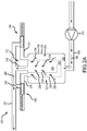
FIG. 2A is a schematic view of a filtration system in a normal mode of operation, in accordance with various embodiments; -
FIG. 2B is a schematic view of a filtration system in a fine filter bypass mode of operation, in accordance with various embodiments; -
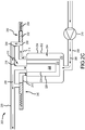
FIG. 2C is a schematic view of a filtration system in a coarse filter bypass mode of operation, in accordance with various embodiments; and -
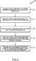
FIG. 3 is a flowchart illustrating a method of filtering a flow of lubricant, in accordance with various embodiments. - The following detailed description of various embodiments herein makes reference to the accompanying drawings, which show various embodiments by way of illustration. While these various embodiments are described in sufficient detail to enable those skilled in the art to practice the disclosure, it should be understood that other embodiments may be realized and that changes may be made without departing from the scope of the disclosure. Thus, the detailed description herein is presented for purposes of illustration only and not of limitation. Furthermore, any reference to singular includes plural embodiments, and any reference to more than one component or step may include a singular embodiment or step. Also, any reference to attached, fixed, connected, or the like may include permanent, removable, temporary, partial, full or any other possible attachment option. Additionally, any reference to without contact (or similar phrases) may also include reduced contact or minimal contact. It should also be understood that unless specifically stated otherwise, references to "a," "an" or "the" may include one or more than one and that reference to an item in the singular may also include the item in the plural. Further, all ranges may include upper and lower values and all ranges and ratio limits disclosed herein may be combined. Further, the term "about" is intended to include a degree of error associated with measurement of a particular quantity based upon equipment or techniques otherwise available at the time of filing the application. For example, "about" may include a range of ±8% or 5% or 2% of a given value.
- Referring now to the drawings,
FIG. 1 schematically illustrates agas turbine engine 20. Thegas turbine engine 20 is disclosed herein as a two-spool turbofan that generally incorporates afan section 22, acompressor section 24, acombustor section 26 and aturbine section 28. Thefan section 22 drives air along a bypass flow path B in a bypass duct defined within anacelle 15, while thecompressor section 24 drives air along a core flow path C for compression and communication into thecombustor section 26 and then expansion through theturbine section 28. Although depicted as a two-spool turbofan gas turbine engine in the disclosed non-limiting embodiment, the concepts described herein are not limited to use with two-spool turbofans as the teachings may be applied to other types of turbine engines. - The
gas turbine engine 20 generally includes alow speed spool 30 and ahigh speed spool 32 mounted for rotation about an engine central longitudinal axis A relative to an enginestatic structure 36 viaseveral bearing systems 38. Various bearing systems at various locations may alternatively or additionally be provided and the location of theseveral bearing systems 38 may be varied as appropriate to the application. Thelow speed spool 30 generally includes aninner shaft 40 that interconnects afan 42, alow pressure compressor 44 and alow pressure turbine 46. Theinner shaft 40 is connected to thefan 42 through a speed change mechanism, which in thisgas turbine engine 20 is illustrated as a fandrive gear system 48 configured to drive thefan 42 at a lower speed than that of thelow speed spool 30. Thehigh speed spool 32 includes anouter shaft 50 that interconnects ahigh pressure compressor 52 and ahigh pressure turbine 54. Acombustor 56 is arranged in thegas turbine engine 20 between thehigh pressure compressor 52 and thehigh pressure turbine 54. Amid-turbine frame 57 of the enginestatic structure 36 is arranged generally between thehigh pressure turbine 54 and thelow pressure turbine 46 and may includeairfoils 59 in the core flow path C for guiding the flow into thelow pressure turbine 46. Themid-turbine frame 57 further supports theseveral bearing systems 38 in theturbine section 28. Theinner shaft 40 and theouter shaft 50 are concentric and rotate via theseveral bearing systems 38 about the engine central longitudinal axis A, which is collinear with longitudinal axes of theinner shaft 40 and theouter shaft 50. - The air in the core flow path C is compressed by the
low pressure compressor 44 and then thehigh pressure compressor 52, mixed and burned with fuel in thecombustor 56, and then expanded over thehigh pressure turbine 54 and thelow pressure turbine 46. Thelow pressure turbine 46 and thehigh pressure turbine 54 rotationally drive the respectivelow speed spool 30 and thehigh speed spool 32 in response to the expansion. It will be appreciated that each of the positions of thefan section 22, thecompressor section 24, thecombustor section 26, theturbine section 28, and the fandrive gear system 48 may be varied. For example, the fandrive gear system 48 may be located aft of thecombustor section 26 or even aft of theturbine section 28, and thefan section 22 may be positioned forward or aft of the location of the fandrive gear system 48. - Referring now to
FIGS. 2A ,2B and2C , afiltration system 200 is illustrated with respect to various modes of operation. Thefiltration system 200 is part of a lubrication system that routes oil or lubricant from a source to one or more bearing or gear assemblies used within a gas turbine engine, such as, for example, one or more of theseveral bearing systems 38 or the fandrive gear system 48 used within thegas turbine engine 20 described above with reference toFIG. 1 . In various embodiments, thefiltration system 200 may be used to filter a flow of lubricant being routed to numerous bearing or gear systems located in numerous places of a gas turbine engine, such as, for example, bearing or gear systems located in thefan section 22, thecompressor section 24, thecombustor section 26 and the fandrive gear system 48 described above with reference toFIG. 1 . - In various embodiments, the
filtration system 200 includes achamber 202 that defines aninterior region 204. Theinterior region 204 is configured to contain oil or lubricant for supply to a bearing or gear system, such as those described above. In particular, a flow oflubricant 206 is provided to theinterior region 204 via aninlet conduit 208 that is supplied by apump 210. As described herein, the flow oflubricant 206 supplied to thechamber 202 is filtered therein and subsequently expelled from thechamber 202 via one or more of a plurality ofexit conduits 212 which, in various embodiments, may include a coarsefilter bypass conduit 214, a finefilter bypass conduit 216 and amain exit conduit 218. In various embodiments, each of the coarsefilter bypass conduit 214, the finefilter bypass conduit 216 and themain exit conduit 218 are routed to anoutlet conduit 220, which is used to route the lubricant to one or more of the bearing or gear systems described above. - In various embodiments, filtration of the flow of
lubricant 206 is accomplished using a dual-filter system 222, although additional numbers of filters may be used in accordance with the principles described herein. For example, as illustrated, the dual-filter system 222 may comprise a fine mesh filter 224 (or a first filter, indicated by dashed lines) and a coarse mesh filter 226 (or a second filter, indicated by dashed lines). In various embodiments, thefine mesh filter 224 defines a first volume 228 (or a first cylindrical volume or fine mesh volume) disposed inside a second volume 230 (or a second cylindrical volume or second mesh volume). Likewise, thechamber 202 or theinterior region 204 may define a third volume (or a third cylindrical volume or chamber volume). Although the volumes defined herein are generally referred to as cylindrical, the disclosure contemplates other volumes, such as, for example, volumes having triangular, square, or N-pentagonal cross sections. In various embodiments, thefirst volume 228 includes the volume within the region defined by thefine mesh filter 224, thesecond volume 230 includes the volume within the region bounded by thecoarse mesh filter 226 and thefine mesh filter 224, and thethird volume 232 includes the volume within the region bounded by the chamber 202 (or a chamber wall 234) and thecoarse mesh filter 226. - Referring now primarily to
FIG. 2A , operation of the filtration system in a normal operational mode is illustrated. As described above, the flow oflubricant 206 is initially provided to thechamber 202. Once in thechamber 202, or in thethird volume 232, thefiltration system 200 is configured such that, in the normal operational mode, the flow oflubricant 206 first passes through thecoarse mesh filter 226 via acoarse mesh flow 236, which flows from thethird volume 232 to thesecond volume 230, and then through thefine mesh filter 224 via afine mesh flow 238, which flows from thesecond volume 230 to thefirst volume 228. As the flow oflubricant 206 passes through thecoarse mesh filter 226 via thecoarse mesh flow 236, particulate matter (e.g., coarse size debris) having a characteristic particulate size greater than a characteristic coarse mesh size (e.g., thirty micrometers to forty micrometers, or 30 - 40 µm) is filtered from the flow oflubricant 206. Similarly, as the flow oflubricant 206 passes through thefine mesh filter 224 via thefine mesh flow 238, particulate matter (e.g., fine size debris) having a characteristic particulate size greater than a characteristic fine mesh size (e.g., three micrometers to six micrometers, or 3 - 6 µm) is filtered from the flow oflubricant 206. Once through thefine mesh filter 224, the flow oflubricant 206 passes through themain exit conduit 218 and is routed to theoutlet conduit 220, which is used to route the flow oflubricant 206 to one or more of the bearing or gear systems described above. - Referring now primarily to
FIG. 2B , operation of the filtration system in a fine filter bypass mode of operation is illustrated. As described above, the flow oflubricant 206 is initially provided to thechamber 202. Once in thechamber 202, or in thethird volume 232, thefiltration system 200 is configured such that, in the fine filter bypass mode of operation, the flow oflubricant 206 first passes through thecoarse mesh filter 226 via acoarse mesh flow 236, which flows from thethird volume 232 to thesecond volume 230. Unlike the normal mode of operation described above with reference toFIG. 2A , in the fine filter bypass mode of operation, thefine mesh filter 224 has become blocked, clogged or otherwise impenetrable (indicated by the solid line), thereby halting the fine mesh flow 238 (seeFIG. 2A ), which would otherwise flow from thesecond volume 230 to thefirst volume 228. In various embodiments, the blocking of thefine mesh filter 224 may occur through the filter becoming clogged with particulate matter (e.g., fine size debris) having a characteristic particulate size greater than a characteristic fine mesh size (e.g., 3 - 6 µm). This may occur over time where the fine size debris builds a layer of debris within or about thefine mesh filter 224 that thereby blocks thefine mesh flow 238 from passing through thefine mesh filter 224. In various embodiments, the blocking of thefine mesh filter 224 may also occur through the filter becoming impenetrable due to the viscous nature of the lubricant. For example, in certain environments, a cold start of an engine may be undertaken at temperatures on the order of minus forty degrees Fahrenheit (-40°F or -40°C) or colder. At such low temperatures, the viscosity of the lubricant may be sufficiently high as to render the lubricant unable to pass through thefine mesh filter 224. Regardless of the mode of blocking, as the lubricant is blocked from passing through thefine mesh filter 224, the pressure within the second volume 230 (or a fine filter pressure) increases. The increase in pressure within thesecond volume 230 acts upon a first bypass valve 240 (or a second volume (230) bypass valve). As a fine filter bypass threshold pressure is reached, thefirst bypass valve 240, which, in various embodiments, may comprise a first plunger 242 (e.g., a first sphere or a first rod) and a first bias mechanism 244 (e.g., a first coil spring), functions to open afirst flow orifice 246, thereby establishing afirst bypass flow 248. Thefirst bypass flow 248, during the fine filter bypass mode of operation, routes the flow oflubricant 206, that would otherwise flow through themain exit conduit 218, through the finefilter bypass conduit 216. Once the flow oflubricant 206 is routed through the finefilter bypass conduit 216, the flow is routed to theoutlet conduit 220, which is used to route the flow oflubricant 206 to one or more of the bearing or gear systems described above. - Referring now primarily to
FIG. 2C , operation of the filtration system in a coarse filter bypass mode of operation is illustrated. As described above, the flow oflubricant 206 is initially provided to thechamber 202. Unlike the normal mode of operation described above with reference toFIG. 2A or the fine filter bypass mode of operation described above with reference toFIG. 2B , in the coarse filter bypass mode of operation, thecoarse mesh filter 226 has become blocked, clogged or otherwise impenetrable (indicated by the solid line), thereby halting the coarse mesh flow 236 (seeFIG. 2B ), which would otherwise flow from thethird volume 232 to thesecond volume 230. In various embodiments, the blocking of thecoarse mesh filter 226 may occur through the filter becoming clogged with particulate matter (e.g., coarse size debris) having a characteristic particulate size greater than a characteristic coarse mesh size (e.g., 30 - 40 µm). This may occur over time where the coarse size debris builds a layer of debris within or about thecoarse mesh filter 226 that thereby blocks thecoarse mesh flow 236 from passing through thecoarse mesh filter 226. In various embodiments, the blocking of thecoarse mesh filter 226 may also occur through the filter becoming impenetrable due to the viscous nature of the lubricant. For example, in certain environments, a cold start of an engine may be undertaken at temperatures on the order of minus forty degrees Fahrenheit (-40°F or -40°C) or colder. At such low temperatures, the viscosity of the lubricant may be sufficiently high so as to render the lubricant unable to pass through thecoarse mesh filter 226. Regardless of the mode of blocking, as the lubricant is blocked from passing through thecoarse mesh filter 226, the pressure within the third volume 232 (or a coarse filter pressure) increases. The increase in pressure within thethird volume 232 acts upon a second bypass valve 250 (or a third volume (232) bypass valve). As a coarse filter bypass threshold pressure is reached, thesecond bypass valve 250, which, in various embodiments, may comprise a second plunger 252 (e.g., a second sphere or a second rod) and a second bias mechanism 254 (e.g., a second coil spring), functions to open asecond flow orifice 256, thereby establishing asecond bypass flow 258. Thesecond bypass flow 258, during the coarse filter bypass mode of operation, routes the flow oflubricant 206, that would otherwise flow through themain exit conduit 218 or through the finefilter bypass conduit 216, through the coarsefilter bypass conduit 214. Once the flow oflubricant 206 is routed through the coarsefilter bypass conduit 214, the flow is routed to theoutlet conduit 220, which is used to route the flow oflubricant 206 to one or more of the bearing system or gear system described above. - Referring now to
FIG. 3 , a method (300) of filtering a flow of lubricant is described, in accordance with various embodiments. Afirst step 302 includes delivering the flow of lubricant to a chamber containing a fine mesh filter and a coarse mesh filter surrounding the fine mesh filter, the fine mesh filter defining a first volume in fluid communication with a main exit conduit. Asecond step 304 includes passing the flow of lubricant through the coarse mesh filter via a coarse mesh flow. Athird step 306 includes passing the flow of lubricant through the fine mesh filter via a fine mesh flow. Afourth step 308 includes bypassing the flow of lubricant from passing through the fine mesh filter upon a fine filter pressure within a second volume defined by the coarse mesh filter and the fine mesh filter reaching a fine filter bypass threshold pressure. Afifth step 310 includes bypassing the flow of lubricant from passing through the coarse mesh filter upon a coarse filter pressure within a third volume defined by the chamber and the coarse mesh filter reaching a coarse filter bypass threshold pressure. In various embodiments, bypassing the flow of lubricant from passing through the fine mesh filter includes opening a first bypass valve and directing the flow of lubricant through a fine filter bypass conduit and into an outlet conduit. In various embodiments, bypassing the flow of lubricant from passing through the coarse mesh filter includes opening a second bypass valve and directing the flow of lubricant through a coarse filter bypass conduit and into the outlet conduit. - Benefits, other advantages, and solutions to problems have been described herein with regard to specific embodiments. Furthermore, the connecting lines shown in the various figures contained herein are intended to represent exemplary functional relationships and/or physical couplings between the various elements. It should be noted that many alternative or additional functional relationships or physical connections may be present in a practical system. However, the benefits, advantages, solutions to problems, and any elements that may cause any benefit, advantage, or solution to occur or become more pronounced are not to be construed as critical, required, or essential features or elements of the disclosure. The scope of the disclosure is accordingly to be limited by nothing other than the appended claims, in which reference to an element in the singular is not intended to mean "one and only one" unless explicitly so stated, but rather "one or more." Moreover, where a phrase similar to "at least one of A, B, or C" is used in the claims, it is intended that the phrase be interpreted to mean that A alone may be present in an embodiment, B alone may be present in an embodiment, C alone may be present in an embodiment, or that any combination of the elements A, B and C may be present in a single embodiment; for example, A and B, A and C, B and C, or A and B and C. Different cross-hatching is used throughout the figures to denote different parts but not necessarily to denote the same or different materials.
- Systems, methods and apparatus are provided herein. In the detailed description herein, references to "one embodiment," "an embodiment," "various embodiments," etc., indicate that the embodiment described may include a particular feature, structure, or characteristic, but every embodiment may not necessarily include the particular feature, structure, or characteristic. Moreover, such phrases are not necessarily referring to the same embodiment. Further, when a particular feature, structure, or characteristic is described in connection with an embodiment, it is submitted that it is within the knowledge of one skilled in the art to affect such feature, structure, or characteristic in connection with other embodiments whether or not explicitly described. After reading the description, it will be apparent to one skilled in the relevant art(s) how to implement the disclosure in alternative embodiments.
- Furthermore, no element, component, or method step in the present disclosure is intended to be dedicated to the public regardless of whether the element, component, or method step is explicitly recited in the claims. No claim element herein is to be construed under the provisions of 35 U.S.C. 112(f) unless the element is expressly recited using the phrase "means for." As used herein, the terms "comprises," "comprising," or any other variation thereof, are intended to cover a non-exclusive inclusion, such that a process, method, article, or apparatus that comprises a list of elements does not include only those elements but may include other elements not expressly listed or inherent to such process, method, article, or apparatus.
- Finally, it should be understood that any of the above described concepts can be used alone or in combination with any or all of the other above described concepts. Although various embodiments have been disclosed and described, one of ordinary skill in this art would recognize that certain modifications would come within the scope of this disclosure. Accordingly, the description is not intended to be exhaustive or to limit the principles described or illustrated herein to any precise form. Many modifications and variations are possible in light of the above teaching.
Claims (15)
- A filtration system, comprising:a fine mesh filter configured for disposition within a chamber and defining a first volume, the first volume in fluid communication with a main exit conduit; anda coarse mesh filter configured for disposition within the chamber and at least partially surrounding the fine mesh filter, the coarse mesh filter and the fine mesh filter defining a second volume, the second volume in fluid communication with a first bypass valve, the coarse mesh filter and the chamber defining a third volume, the third volume in fluid communication with a second bypass valve.
- The filtration system of claim 1, wherein the fine mesh filter defines a characteristic fine mesh size and the coarse mesh filter defines a characteristic coarse mesh size greater than the characteristic fine mesh size.
- The filtration system of claim 2, wherein the characteristic coarse mesh size is about thirty micrometers to about forty micrometers.
- The filtration system of claim 2 or 3, wherein the characteristic fine mesh size is about three micrometers to about six micrometers.
- The filtration system of any preceding claim, wherein the first bypass valve is configured to fluidly couple a fine filter bypass conduit to the second volume.
- The filtration system of claim 5, wherein the second bypass valve is configured to fluidly couple a coarse filter bypass conduit to the third volume.
- The filtration system of claim 5 or 6, wherein the fine filter bypass conduit is fluidly coupled to the main exit conduit and to an outlet conduit.
- The filtration system of claim 7, wherein the coarse filter bypass conduit is fluidly coupled to the main exit conduit and to the outlet conduit.
- The filtration system of any preceding claim, wherein the first bypass valve includes a first bias mechanism responsive to a fine filter bypass threshold pressure.
- The filtration system of claim 9, wherein the second bypass valve includes a second bias mechanism responsive to a coarse filter bypass threshold pressure, wherein, optionally, the coarse filter bypass threshold pressure is greater than the fine filter bypass threshold pressure.
- A filtration system as claimed in any preceding claim, the filtration system being for a gas turbine engine and further comprising
a chamber. - The filtration system of claim 11, wherein the main exit conduit is fluidly coupled to an outlet conduit, the outlet conduit configured to provide a lubricant to a component within the gas turbine engine.
- The filtration system of claim 12, wherein the component is a bearing system or a gear system.
- A method of filtering a flow of lubricant, comprising:delivering the flow of lubricant to a chamber containing a fine mesh filter and a coarse mesh filter surrounding the fine mesh filter, the fine mesh filter defining a first volume in fluid communication with a main exit conduit;passing the flow of lubricant through the coarse mesh filter via a coarse mesh flow;passing the flow of lubricant through the fine mesh filter via a fine mesh flow;bypassing the flow of lubricant from passing through the fine mesh filter upon a fine filter pressure within a second volume defined by the coarse mesh filter and the fine mesh filter reaching a fine filter bypass threshold pressure; andbypassing the flow of lubricant from passing through the coarse mesh filter upon a coarse filter pressure within a third volume defined by the chamber and the coarse mesh filter reaching a coarse filter bypass threshold pressure.
- The method of claim 14, wherein bypassing the flow of lubricant from passing through the fine mesh filter includes opening a first bypass valve and directing the flow of lubricant through a fine filter bypass conduit and into an outlet conduit, wherein, optionally, bypassing the flow of lubricant from passing through the coarse mesh filter includes opening a second bypass valve and directing the flow of lubricant through a coarse filter bypass conduit and into the outlet conduit.
Applications Claiming Priority (1)
| Application Number | Priority Date | Filing Date | Title |
|---|---|---|---|
| US16/555,813 US11154799B2 (en) | 2019-08-29 | 2019-08-29 | Dual bypass filter cascade |
Publications (2)
| Publication Number | Publication Date |
|---|---|
| EP3786420A1 true EP3786420A1 (en) | 2021-03-03 |
| EP3786420B1 EP3786420B1 (en) | 2023-06-14 |
Family
ID=72088023
Family Applications (1)
| Application Number | Title | Priority Date | Filing Date |
|---|---|---|---|
| EP20191221.9A Active EP3786420B1 (en) | 2019-08-29 | 2020-08-14 | Dual bypass filter cascade |
Country Status (2)
| Country | Link |
|---|---|
| US (1) | US11154799B2 (en) |
| EP (1) | EP3786420B1 (en) |
Families Citing this family (2)
| Publication number | Priority date | Publication date | Assignee | Title |
|---|---|---|---|---|
| US20250109701A1 (en) * | 2023-09-29 | 2025-04-03 | Pratt & Whitney Candada Corp. | Lubricant filter system, aircraft engine, and method of operating a lubricant system |
| US20250361820A1 (en) * | 2024-05-24 | 2025-11-27 | Pratt & Whitney Canada Corp. | Engine oil system for an aircraft propulsion system |
Citations (5)
| Publication number | Priority date | Publication date | Assignee | Title |
|---|---|---|---|---|
| US4512299A (en) * | 1983-12-12 | 1985-04-23 | International Harvester Company | Automotive engine with improved multifilter lubrication system |
| JPS6278420A (en) * | 1985-09-30 | 1987-04-10 | Mazda Motor Corp | Lubrication device for turbocharged engine |
| US4905644A (en) * | 1988-04-13 | 1990-03-06 | Societe Nationale D'etude Et De Construction De Moteurs D'aviation "S.N.E.C.M.A" | Self cleaning by-pass filtration arrangement |
| US20180230854A1 (en) * | 2015-02-10 | 2018-08-16 | United Technologies Corporation | Turbine engine lubrication system with wash flow filter |
| EP3412878A1 (en) * | 2017-06-05 | 2018-12-12 | United Technologies Corporation | Oil filtration system |
Family Cites Families (4)
| Publication number | Priority date | Publication date | Assignee | Title |
|---|---|---|---|---|
| US3397786A (en) | 1967-07-17 | 1968-08-20 | Champion Lab Inc | Dual element filter assembly having plural valves therein |
| US3390774A (en) | 1967-08-28 | 1968-07-02 | Chevron Res | Spin-on type filter with dual valve and dual filter media |
| US7479219B2 (en) | 2004-08-05 | 2009-01-20 | Guenther Rassinger | Filter device for fluids and method for filtering fluids |
| US20110147322A1 (en) | 2009-12-17 | 2011-06-23 | Honeywell International Inc. | Lubricant supply filtration system and method |
-
2019
- 2019-08-29 US US16/555,813 patent/US11154799B2/en active Active
-
2020
- 2020-08-14 EP EP20191221.9A patent/EP3786420B1/en active Active
Patent Citations (5)
| Publication number | Priority date | Publication date | Assignee | Title |
|---|---|---|---|---|
| US4512299A (en) * | 1983-12-12 | 1985-04-23 | International Harvester Company | Automotive engine with improved multifilter lubrication system |
| JPS6278420A (en) * | 1985-09-30 | 1987-04-10 | Mazda Motor Corp | Lubrication device for turbocharged engine |
| US4905644A (en) * | 1988-04-13 | 1990-03-06 | Societe Nationale D'etude Et De Construction De Moteurs D'aviation "S.N.E.C.M.A" | Self cleaning by-pass filtration arrangement |
| US20180230854A1 (en) * | 2015-02-10 | 2018-08-16 | United Technologies Corporation | Turbine engine lubrication system with wash flow filter |
| EP3412878A1 (en) * | 2017-06-05 | 2018-12-12 | United Technologies Corporation | Oil filtration system |
Also Published As
| Publication number | Publication date |
|---|---|
| US20210060461A1 (en) | 2021-03-04 |
| EP3786420B1 (en) | 2023-06-14 |
| US11154799B2 (en) | 2021-10-26 |
Similar Documents
| Publication | Publication Date | Title |
|---|---|---|
| US9849411B2 (en) | Scavenge filter system for a gas turbine engine | |
| US20190186297A1 (en) | Fan drive gear system manifold radial tube filters | |
| US20180347400A1 (en) | Turbine engine lubrication system with wash flow filter | |
| US9995177B2 (en) | Self cleaning debris filter for fan drive gear system | |
| US20140294558A1 (en) | Turbomachine fluid delivery manifold and system | |
| EP3258085B1 (en) | Oil loss protection for a fan drive gear system | |
| CN110388270A (en) | Gas turbine engine | |
| EP3786420B1 (en) | Dual bypass filter cascade | |
| EP3885557B1 (en) | Integrated environmental control and buffer air system | |
| EP3428411B1 (en) | Gas turbine engine and corresponding method of cooling | |
| US20170362959A1 (en) | Lubrication system with multiple lubrication circuits | |
| EP3239545B1 (en) | Integrated oil supply tube and check valve | |
| CN107916994A (en) | Gas-turbine unit | |
| EP3412878B1 (en) | Oil filtration system | |
| EP3249176B1 (en) | Dirt shield | |
| US9840966B2 (en) | Auxiliaryy fluid flow system debris filter | |
| US11692483B2 (en) | System for lubricating components of a gas turbine engine including a lubricant bypass conduit | |
| US20190024525A1 (en) | Seal anti-rotation | |
| EP4534823A2 (en) | Particulate separator assembly for a gas turbine engine |
Legal Events
| Date | Code | Title | Description |
|---|---|---|---|
| PUAI | Public reference made under article 153(3) epc to a published international application that has entered the european phase |
Free format text: ORIGINAL CODE: 0009012 |
|
| STAA | Information on the status of an ep patent application or granted ep patent |
Free format text: STATUS: THE APPLICATION HAS BEEN PUBLISHED |
|
| AK | Designated contracting states |
Kind code of ref document: A1 Designated state(s): AL AT BE BG CH CY CZ DE DK EE ES FI FR GB GR HR HU IE IS IT LI LT LU LV MC MK MT NL NO PL PT RO RS SE SI SK SM TR |
|
| AX | Request for extension of the european patent |
Extension state: BA ME |
|
| STAA | Information on the status of an ep patent application or granted ep patent |
Free format text: STATUS: REQUEST FOR EXAMINATION WAS MADE |
|
| 17P | Request for examination filed |
Effective date: 20210902 |
|
| RBV | Designated contracting states (corrected) |
Designated state(s): AL AT BE BG CH CY CZ DE DK EE ES FI FR GB GR HR HU IE IS IT LI LT LU LV MC MK MT NL NO PL PT RO RS SE SI SK SM TR |
|
| GRAP | Despatch of communication of intention to grant a patent |
Free format text: ORIGINAL CODE: EPIDOSNIGR1 |
|
| STAA | Information on the status of an ep patent application or granted ep patent |
Free format text: STATUS: GRANT OF PATENT IS INTENDED |
|
| RIC1 | Information provided on ipc code assigned before grant |
Ipc: F01D 25/18 20060101AFI20221208BHEP |
|
| INTG | Intention to grant announced |
Effective date: 20230102 |
|
| GRAS | Grant fee paid |
Free format text: ORIGINAL CODE: EPIDOSNIGR3 |
|
| GRAA | (expected) grant |
Free format text: ORIGINAL CODE: 0009210 |
|
| STAA | Information on the status of an ep patent application or granted ep patent |
Free format text: STATUS: THE PATENT HAS BEEN GRANTED |
|
| AK | Designated contracting states |
Kind code of ref document: B1 Designated state(s): AL AT BE BG CH CY CZ DE DK EE ES FI FR GB GR HR HU IE IS IT LI LT LU LV MC MK MT NL NO PL PT RO RS SE SI SK SM TR |
|
| REG | Reference to a national code |
Ref country code: CH Ref legal event code: EP |
|
| REG | Reference to a national code |
Ref country code: DE Ref legal event code: R096 Ref document number: 602020012449 Country of ref document: DE |
|
| REG | Reference to a national code |
Ref country code: AT Ref legal event code: REF Ref document number: 1579383 Country of ref document: AT Kind code of ref document: T Effective date: 20230715 |
|
| REG | Reference to a national code |
Ref country code: LT Ref legal event code: MG9D |
|
| REG | Reference to a national code |
Ref country code: NL Ref legal event code: MP Effective date: 20230614 |
|
| PG25 | Lapsed in a contracting state [announced via postgrant information from national office to epo] |
Ref country code: SE Free format text: LAPSE BECAUSE OF FAILURE TO SUBMIT A TRANSLATION OF THE DESCRIPTION OR TO PAY THE FEE WITHIN THE PRESCRIBED TIME-LIMIT Effective date: 20230614 Ref country code: NO Free format text: LAPSE BECAUSE OF FAILURE TO SUBMIT A TRANSLATION OF THE DESCRIPTION OR TO PAY THE FEE WITHIN THE PRESCRIBED TIME-LIMIT Effective date: 20230914 Ref country code: ES Free format text: LAPSE BECAUSE OF FAILURE TO SUBMIT A TRANSLATION OF THE DESCRIPTION OR TO PAY THE FEE WITHIN THE PRESCRIBED TIME-LIMIT Effective date: 20230614 |
|
| RAP4 | Party data changed (patent owner data changed or rights of a patent transferred) |
Owner name: RTX CORPORATION |
|
| REG | Reference to a national code |
Ref country code: AT Ref legal event code: MK05 Ref document number: 1579383 Country of ref document: AT Kind code of ref document: T Effective date: 20230614 |
|
| PG25 | Lapsed in a contracting state [announced via postgrant information from national office to epo] |
Ref country code: RS Free format text: LAPSE BECAUSE OF FAILURE TO SUBMIT A TRANSLATION OF THE DESCRIPTION OR TO PAY THE FEE WITHIN THE PRESCRIBED TIME-LIMIT Effective date: 20230614 Ref country code: NL Free format text: LAPSE BECAUSE OF FAILURE TO SUBMIT A TRANSLATION OF THE DESCRIPTION OR TO PAY THE FEE WITHIN THE PRESCRIBED TIME-LIMIT Effective date: 20230614 Ref country code: LV Free format text: LAPSE BECAUSE OF FAILURE TO SUBMIT A TRANSLATION OF THE DESCRIPTION OR TO PAY THE FEE WITHIN THE PRESCRIBED TIME-LIMIT Effective date: 20230614 Ref country code: LT Free format text: LAPSE BECAUSE OF FAILURE TO SUBMIT A TRANSLATION OF THE DESCRIPTION OR TO PAY THE FEE WITHIN THE PRESCRIBED TIME-LIMIT Effective date: 20230614 Ref country code: HR Free format text: LAPSE BECAUSE OF FAILURE TO SUBMIT A TRANSLATION OF THE DESCRIPTION OR TO PAY THE FEE WITHIN THE PRESCRIBED TIME-LIMIT Effective date: 20230614 Ref country code: GR Free format text: LAPSE BECAUSE OF FAILURE TO SUBMIT A TRANSLATION OF THE DESCRIPTION OR TO PAY THE FEE WITHIN THE PRESCRIBED TIME-LIMIT Effective date: 20230915 |
|
| PG25 | Lapsed in a contracting state [announced via postgrant information from national office to epo] |
Ref country code: FI Free format text: LAPSE BECAUSE OF FAILURE TO SUBMIT A TRANSLATION OF THE DESCRIPTION OR TO PAY THE FEE WITHIN THE PRESCRIBED TIME-LIMIT Effective date: 20230614 |
|
| PG25 | Lapsed in a contracting state [announced via postgrant information from national office to epo] |
Ref country code: SK Free format text: LAPSE BECAUSE OF FAILURE TO SUBMIT A TRANSLATION OF THE DESCRIPTION OR TO PAY THE FEE WITHIN THE PRESCRIBED TIME-LIMIT Effective date: 20230614 |
|
| PG25 | Lapsed in a contracting state [announced via postgrant information from national office to epo] |
Ref country code: IS Free format text: LAPSE BECAUSE OF FAILURE TO SUBMIT A TRANSLATION OF THE DESCRIPTION OR TO PAY THE FEE WITHIN THE PRESCRIBED TIME-LIMIT Effective date: 20231014 |
|
| PG25 | Lapsed in a contracting state [announced via postgrant information from national office to epo] |
Ref country code: SM Free format text: LAPSE BECAUSE OF FAILURE TO SUBMIT A TRANSLATION OF THE DESCRIPTION OR TO PAY THE FEE WITHIN THE PRESCRIBED TIME-LIMIT Effective date: 20230614 Ref country code: SK Free format text: LAPSE BECAUSE OF FAILURE TO SUBMIT A TRANSLATION OF THE DESCRIPTION OR TO PAY THE FEE WITHIN THE PRESCRIBED TIME-LIMIT Effective date: 20230614 Ref country code: RO Free format text: LAPSE BECAUSE OF FAILURE TO SUBMIT A TRANSLATION OF THE DESCRIPTION OR TO PAY THE FEE WITHIN THE PRESCRIBED TIME-LIMIT Effective date: 20230614 Ref country code: PT Free format text: LAPSE BECAUSE OF FAILURE TO SUBMIT A TRANSLATION OF THE DESCRIPTION OR TO PAY THE FEE WITHIN THE PRESCRIBED TIME-LIMIT Effective date: 20231016 Ref country code: IS Free format text: LAPSE BECAUSE OF FAILURE TO SUBMIT A TRANSLATION OF THE DESCRIPTION OR TO PAY THE FEE WITHIN THE PRESCRIBED TIME-LIMIT Effective date: 20231014 Ref country code: EE Free format text: LAPSE BECAUSE OF FAILURE TO SUBMIT A TRANSLATION OF THE DESCRIPTION OR TO PAY THE FEE WITHIN THE PRESCRIBED TIME-LIMIT Effective date: 20230614 Ref country code: CZ Free format text: LAPSE BECAUSE OF FAILURE TO SUBMIT A TRANSLATION OF THE DESCRIPTION OR TO PAY THE FEE WITHIN THE PRESCRIBED TIME-LIMIT Effective date: 20230614 Ref country code: AT Free format text: LAPSE BECAUSE OF FAILURE TO SUBMIT A TRANSLATION OF THE DESCRIPTION OR TO PAY THE FEE WITHIN THE PRESCRIBED TIME-LIMIT Effective date: 20230614 |
|
| PG25 | Lapsed in a contracting state [announced via postgrant information from national office to epo] |
Ref country code: PL Free format text: LAPSE BECAUSE OF FAILURE TO SUBMIT A TRANSLATION OF THE DESCRIPTION OR TO PAY THE FEE WITHIN THE PRESCRIBED TIME-LIMIT Effective date: 20230614 |
|
| PG25 | Lapsed in a contracting state [announced via postgrant information from national office to epo] |
Ref country code: MC Free format text: LAPSE BECAUSE OF FAILURE TO SUBMIT A TRANSLATION OF THE DESCRIPTION OR TO PAY THE FEE WITHIN THE PRESCRIBED TIME-LIMIT Effective date: 20230614 |
|
| REG | Reference to a national code |
Ref country code: DE Ref legal event code: R097 Ref document number: 602020012449 Country of ref document: DE |
|
| REG | Reference to a national code |
Ref country code: CH Ref legal event code: PL |
|
| PG25 | Lapsed in a contracting state [announced via postgrant information from national office to epo] |
Ref country code: MC Free format text: LAPSE BECAUSE OF FAILURE TO SUBMIT A TRANSLATION OF THE DESCRIPTION OR TO PAY THE FEE WITHIN THE PRESCRIBED TIME-LIMIT Effective date: 20230614 |
|
| PG25 | Lapsed in a contracting state [announced via postgrant information from national office to epo] |
Ref country code: LU Free format text: LAPSE BECAUSE OF NON-PAYMENT OF DUE FEES Effective date: 20230814 |
|
| PLBE | No opposition filed within time limit |
Free format text: ORIGINAL CODE: 0009261 |
|
| STAA | Information on the status of an ep patent application or granted ep patent |
Free format text: STATUS: NO OPPOSITION FILED WITHIN TIME LIMIT |
|
| PG25 | Lapsed in a contracting state [announced via postgrant information from national office to epo] |
Ref country code: LU Free format text: LAPSE BECAUSE OF NON-PAYMENT OF DUE FEES Effective date: 20230814 Ref country code: DK Free format text: LAPSE BECAUSE OF FAILURE TO SUBMIT A TRANSLATION OF THE DESCRIPTION OR TO PAY THE FEE WITHIN THE PRESCRIBED TIME-LIMIT Effective date: 20230614 Ref country code: CH Free format text: LAPSE BECAUSE OF NON-PAYMENT OF DUE FEES Effective date: 20230831 |
|
| PG25 | Lapsed in a contracting state [announced via postgrant information from national office to epo] |
Ref country code: SI Free format text: LAPSE BECAUSE OF FAILURE TO SUBMIT A TRANSLATION OF THE DESCRIPTION OR TO PAY THE FEE WITHIN THE PRESCRIBED TIME-LIMIT Effective date: 20230614 |
|
| REG | Reference to a national code |
Ref country code: BE Ref legal event code: MM Effective date: 20230831 |
|
| 26N | No opposition filed |
Effective date: 20240315 |
|
| REG | Reference to a national code |
Ref country code: IE Ref legal event code: MM4A |
|
| PG25 | Lapsed in a contracting state [announced via postgrant information from national office to epo] |
Ref country code: SI Free format text: LAPSE BECAUSE OF FAILURE TO SUBMIT A TRANSLATION OF THE DESCRIPTION OR TO PAY THE FEE WITHIN THE PRESCRIBED TIME-LIMIT Effective date: 20230614 Ref country code: IT Free format text: LAPSE BECAUSE OF FAILURE TO SUBMIT A TRANSLATION OF THE DESCRIPTION OR TO PAY THE FEE WITHIN THE PRESCRIBED TIME-LIMIT Effective date: 20230614 |
|
| PG25 | Lapsed in a contracting state [announced via postgrant information from national office to epo] |
Ref country code: IE Free format text: LAPSE BECAUSE OF NON-PAYMENT OF DUE FEES Effective date: 20230814 |
|
| PG25 | Lapsed in a contracting state [announced via postgrant information from national office to epo] |
Ref country code: IE Free format text: LAPSE BECAUSE OF NON-PAYMENT OF DUE FEES Effective date: 20230814 |
|
| PG25 | Lapsed in a contracting state [announced via postgrant information from national office to epo] |
Ref country code: BE Free format text: LAPSE BECAUSE OF NON-PAYMENT OF DUE FEES Effective date: 20230831 |
|
| PG25 | Lapsed in a contracting state [announced via postgrant information from national office to epo] |
Ref country code: BG Free format text: LAPSE BECAUSE OF FAILURE TO SUBMIT A TRANSLATION OF THE DESCRIPTION OR TO PAY THE FEE WITHIN THE PRESCRIBED TIME-LIMIT Effective date: 20230614 |
|
| PG25 | Lapsed in a contracting state [announced via postgrant information from national office to epo] |
Ref country code: BG Free format text: LAPSE BECAUSE OF FAILURE TO SUBMIT A TRANSLATION OF THE DESCRIPTION OR TO PAY THE FEE WITHIN THE PRESCRIBED TIME-LIMIT Effective date: 20230614 |
|
| PG25 | Lapsed in a contracting state [announced via postgrant information from national office to epo] |
Ref country code: CY Free format text: LAPSE BECAUSE OF FAILURE TO SUBMIT A TRANSLATION OF THE DESCRIPTION OR TO PAY THE FEE WITHIN THE PRESCRIBED TIME-LIMIT; INVALID AB INITIO Effective date: 20200814 |
|
| PG25 | Lapsed in a contracting state [announced via postgrant information from national office to epo] |
Ref country code: HU Free format text: LAPSE BECAUSE OF FAILURE TO SUBMIT A TRANSLATION OF THE DESCRIPTION OR TO PAY THE FEE WITHIN THE PRESCRIBED TIME-LIMIT; INVALID AB INITIO Effective date: 20200814 |
|
| REG | Reference to a national code |
Ref country code: DE Ref legal event code: R081 Ref document number: 602020012449 Country of ref document: DE Owner name: RTX CORPORATION (N.D.GES.D. STAATES DELAWARE),, US Free format text: FORMER OWNER: RAYTHEON TECHNOLOGIES CORPORATION, FARMINGTON, CT, US |
|
| PGFP | Annual fee paid to national office [announced via postgrant information from national office to epo] |
Ref country code: DE Payment date: 20250724 Year of fee payment: 6 |
|
| PGFP | Annual fee paid to national office [announced via postgrant information from national office to epo] |
Ref country code: GB Payment date: 20250725 Year of fee payment: 6 |
|
| PGFP | Annual fee paid to national office [announced via postgrant information from national office to epo] |
Ref country code: FR Payment date: 20250725 Year of fee payment: 6 |
|
| PG25 | Lapsed in a contracting state [announced via postgrant information from national office to epo] |
Ref country code: TR Free format text: LAPSE BECAUSE OF FAILURE TO SUBMIT A TRANSLATION OF THE DESCRIPTION OR TO PAY THE FEE WITHIN THE PRESCRIBED TIME-LIMIT Effective date: 20230614 |
|
| P01 | Opt-out of the competence of the unified patent court (upc) registered |
Free format text: CASE NUMBER: UPC_APP_0019238_3786420/2025 Effective date: 20251223 |